Submitted:
30 May 2025
Posted:
30 May 2025
You are already at the latest version
Abstract
Clos networks and their folded versions, fat-trees, are widely adopted in interconnection network designs for data centers and supercomputers. There are two main types of Clos networks: strictly nonblocking Clos networks and rearrangeably nonblocking Clos networks. Strictly nonblocking Clos networks can connect an idle input to an idle output without interfering with existing connections. Rearrangeably nonblocking Clos networks can connect an idle input to an idle output with rearrangements of existing connections. Traditional strictly nonblocking Clos networks have two drawbacks. One drawback is the use of crossbars with different numbers of input and output ports, whereas the currently available switches are square crossbars with the same number of input and output ports. Another drawback is that every connection goes through a fixed number of stages, increasing the length of the communication path. A drawback of traditional fat-trees is that the root stage uses different sized crossbar switches than the other stages. To solve these problems, we propose an Identical Strictly NonBlocking folded Clos (ISNBC) network that uses equally sized square crossbars for all switches. Correspondingly, we also propose an Identical Rearrangeably NonBlocking folded Clos (IRNBC) network. Both ISNBC and IRNBC networks can have any number of stages, can use equally sized square crossbars with no unused switch ports, and can utilize shortcut connections to reduce communication path lengths. Moreover, both ISNBC and IRNBC networks have a lower switch crosspoint cost ratio to a single crossbar than their corresponding traditional Clos networks.
Keywords:
multistage interconnection networks
; strictly nonblocking
; rearrangeably nonblocking
; Clos network
; folded Clos network
; fat-tree
; k-ary n-tree
; square crossbar switch
; crosspoint ratio
1. Introduction
Clos networks [1] and fat-trees [2] have been widely used in interconnection network designs for modern data centers and supercomputers [3]. A traditional unidirectional nonblocking Clos network was originally designed for telecommunications. It is a type of multistage circuit-switching network that replaces a single large crossbar to reduce hardware costs in terms of crosspoints.
A 3-stage traditional unidirectional Clos network topology [1] is parameterized by two integers n and m, where n is the number of sources connecting to an ingress stage crossbar switch, the number of destinations connecting to an egress stage crossbar switch is also n, and m is the number of crossbar switches in the middle stage. The ingress stage has n crossbar switches, and the number of crossbar switches in the egress stage is also n. Therefore, the total number of sources is , and the total number of destinations is also . A switch in the ingress stage is an (n inputs and m outputs) crossbar. A switch in the egress stage is an crossbar. A switch in the middle stage is an crossbar. There is exactly one connection between each ingress stage switch and each middle stage switch. And there is exactly one connection between each middle stage switch and each egress stage switch. If , it is a strictly nonblocking network, meaning that the network can connect a free source to a free destination without interfering with existing connections. If , it is a rearrangeably nonblocking network, meaning that the network can connect a free source to a free destination with rearrangements of existing connections.
Traditional unidirectional strictly nonblocking Clos networks have two drawbacks. One drawback is that all connections from sources to destinations pass through a fixed number of stages. For example, the path length in a 3-stage unidirectional Clos network is always 4. Another drawback is that it uses and crossbars with different numbers of input and output ports. However, nowadays the available switches are square crossbars with the same number of input and output ports. If we use the same square crossbars for all switches, there will be a large number of unused ports.
A fat-tree is a folded version of the Clos network [4]. It merges the corresponding ingress and egress switches. Then the merged stage is called a leaf stage and the middle stage is called a root stage. A fat-tree can utilize shortcut connections. That is, a connection does not have to go through all stages. For example, if the source and destination are connected to the same leaf switch, the connection does not need to go to the root stage. Thus, the path length will be 2 instead of 4. A drawback of fat-tree networks is that the root stage uses different sized crossbar switches than the other stages.
A k-ary n-tree [5] is a kind of parametric fat-tree, where k is the arity or number of links of a switch that connects to the previous or next stage, and n is the number of stages. That is, the switch radix is . A k-ary n-tree Clos network can be constructed with back-to-back k-ary n-fly butterfly [6]. The 2-ary n-tree Clos network is also called the Bene network [7]. A k-ary fat-tree [8] is a bidirectional ()-ary n-tree Clos network where k is even.
A packet can be routed to an arbitrary middle switch in a rearrangeably nonblocking Clos network or an arbitrary root switch in a rearrangeably nonblocking folded Clos network and then to their ultimate destination. This increases hardware cost and packet latency. Mirrored k-ary n-tree networks [9] and peer k-ary n-tree networks [10] focus on increasing network capacity and reducing hardware costs and packet latency.
A strictly nonblocking folded Clos network using same sized crossbar switches is proposed in [11]. The proposed network has a 2-stage structure and uses multiple links between a leaf switch and a root switch. It may have unused switch ports. The number of unused switch ports is reduced by adjusting the number of leaf switches, but the existence of unused switch ports increases the hardware cost. A flexible folded Clos network is proposed in [12]. To reduce the blocking probability, a second group of switches is added to the root stage. [13] extends the number of groups from two to a general number S. All these networks have only two stages, making it difficult to scale the network.
The new contributions of this paper are summarized as follows. We propose an Identical Strictly NonBlocking folded Clos (ISNBC) network and an Identical Rearrangeably NonBlocking folded Clos (IRNBC) network. Both ISNBC and IRNBC networks can have any number of stages to increase the system’s scalability, can use equally sized square crossbars with no unused switch ports to accommodate currently available switches at low costs, and can utilize shortcut connections to reduce communication path lengths. Moreover, both ISNBC and IRNBC networks have a lower crosspoint ratio to a single crossbar than their corresponding traditional nonblocking Clos networks.
The rest of the paper is organized as follows. In Section 2, we review some related multistage interconnection networks. In Section 3, we propose identical strictly and rearrangeably nonblocking folded Clos networks consisting of equally sized square crossbars. In Section 4, we evaluate the hardware cost from the crosspoint perspective and show that the costs of the proposed networks are lower than their corresponding traditional networks. We conclude the paper and suggest some future research topics in Section 5.
2. Related Works
There are many different types of multistage interconnection networks. This section reviews some related multistage interconnection networks.
2.1. Traditional Nonblocking Clos Networks
A traditional unidirectional strictly nonblocking Clos network [1] has odd switch stages. Consider a traditional unidirectional strictly nonblocking Clos network with three switch stages: The ingress stage has n switches, and each switch is an (n inputs and m outputs) crossbar. The middle stage has m switches, and each switch is an crossbar. The egress stage has n switches, and each switch is an crossbar. The m outputs of an ingress switch are connected to m middle switches: Each output is connected to a different middle switch. The n outputs of a middle switch are connected to n egress switches: Each output is connected to a different egress switch. That is, there is exactly one connection between each ingress stage switch and each middle stage switch. And, there is exactly one connection between each middle stage switch and each egress stage switch. The total number of switches is , and the total number of compute nodes is . We can see that crossbar switches with different numbers of input and output ports are used at the ingress and egress stages.
Assume that connections have been built, which means that an ingress switch has an idle input and an egress switch has an idle output. We want to build a connection from the idle input to the idle output without interfering with existing connections. This is called strictly nonblocking. Suppose that the idle input is at switch i in the ingress stage, and the idle output is at switch j in the egress stage. That is, connections were built in switch i, and connections were built in switch j. In the worst case, these connections used switches in the middle stage. If we have another switch in the middle stage, we can build a connection from the idle input to the idle output through that switch without interfering with existing connections. Therefore, the condition to achieve strictly nonblocking is .
An (x inputs and y outputs) crossbar has crosspoints. Let . Then there are crosspoints in a traditional unidirectional strictly nonblocking Clos network. There are inputs and outputs. If we use a single crossbar, it requires crosspoints. For , the Clos network requires crosspoints, less than crosspoints in the single crossbar’s implementation.
A folded version of the traditional unidirectional strictly nonblocking Clos network can be constructed by combining ingress and egress switches to form leaf switches. The middle switches become root switches. A leaf switch is an crossbar. A root switch is still an crossbar. We can see that the different sized crossbar switches are used at the leaf and root stages.
A Clos network is rearrangeably nonblocking if and only if . In such a case, an input of an ingress switch can be connected to an output of an egress switch using a middle switch. A folded version of the traditional unidirectional rearrangeably nonblocking Clos network can be constructed by combining ingress and egress switches.
Traditional unidirectional strictly nonblocking Clos networks use crossbars with different numbers of input and output ports. The root stage of the folded version of the traditional unidirectional strictly and rearrangeably nonblocking Clos networks uses different sized crossbar switches than the other stages.
2.2. K-Ary N-Tree Clos Networks
A k-ary n-tree Clos network can be created with k-ary n-fly butterfly networks. A k-ary n-fly butterfly network [6] has compute nodes. It has n stages. Each stage has switches and each switch has k input ports and k output ports ( is the radix of the switch). A k-ary 1-fly butterfly network has a switch. There are k input ports and k output ports. Each of compute nodes is connected to an input port and an output port. A k-ary 2-fly butterfly network has two stages: stage 0 and stage 1. Each stage has k switches. compute nodes are connected to the input ports of switches in stage 0 and the output ports of switches in stage 1. Each output port of a switch in stage 0 is connected to an input port of a different switch in stage 1.
Butterfly minimizes the network diameter and reduces the network cost. However, there is a lack of path diversity because there is only one path between the source node and the destination node. Butterfly is a blocking network. In addition, it cannot exploit the locality of traffic because all packets must traverse the diameter of the network [4].
Multistage rearrangeably nonblocking Clos networks are also called k-ary n-tree Clos networks. A k-ary n-tree Clos network can be created by combining two k-ary n-fly butterfly networks [6] back-to-back where the two back stages are fused [4]. There are stages. The stages on the left to the middle stage form an input network and the stages on the right to the middle stage form an output network. It solves the problem of lack of path diversity in butterfly networks. The input network can route packets from any source compute node to any middle stage switch. The output network can route packets from any middle stage switch to any destination compute node. Like a k-ary n-fly butterfly network, the links in a k-ary n-tree Clos network are also unidirectional.
When , the k-ary n-tree Clos network is also called the Bene network [7]. There are () stages where N is the number of compute nodes. Each stage contains switches and each switch is a crossbar. For example, a 3-stage Bene network has 4 compute nodes, a 5-stage Bene network has 8 compute nodes, and a 7-stage Bene network has 16 compute nodes.
In a k-ary n-tree Clos network, a packet needs to be routed first to an arbitrary middle stage switch and then to its ultimate destination. It is a rearrangeably nonblocking network. The cost and latency of a k-ary n-tree Clos network is nearly double that of a k-ary n-fly butterfly network with equal node capacity [4].
Because in a unidirectional k-ary n-tree Clos network, the nodes in the input side and the nodes in the output side at the same row are the same compute nodes, and the ports of a switch are unidirectional, we can fold the unidirectional k-ary n-tree Clos network and combine two unidirectional switches to a bidirectional switch. And, we use bidirectional links to connect switch ports. We call it a k-ary n-tree folded Clos network, or a k-ary n-tree fat-tree [5]. It has n stages and compute nodes.
A k-ary n-tree fat-tree network can be thought of as a bidirectional k-ary n-fly butterfly network with compute nodes connected to stage 0. Compared to the unidirectional k-ary n-tree Clos network, a k-ary n-tree fat-tree network can exploit the traffic locality, because a packet needs to be routed only to a nearest common ancestor (NCA) of the source and destination and then to its ultimate destination. This means that packets may no longer need to be routed to the root switch, reducing the path they take.
We can re-design the switches in a unidirectional k-ary n-tree Clos network so that the switches have bidirectional ports. Also, we use the bidirectional links and double the number of compute nodes (the left nodes and right nodes are distinct compute nodes). Thus, we get a bidirectional k-ary n-tree Clos network. It has stages and compute nodes. All the switches in a bidirectional k-ary n-tree Clos network have the same radix which is .
When and k is even, the bidirectional ()-ary n-tree Clos network is also called the k-ary fat-tree network [8]. It has a fixed 3 stages (layers). The root stage is called a core (spine) layer. There are k pods below the core layer. Each pod contains two layers: the aggregation layer in the middle stage and the edge layer in the leaf stage.
2.3. Mirrored and Peer K-Ary N-Tree Networks
To implement the nonblocking routing, the network must provide a high path diversity so that a packet can be routed to an arbitrary middle stage switch in a Clos network or an arbitrary root switch in a fat-tree network and then to their ultimate destination. This approximately doubles the number of switches and links, resulting in a high hardware cost and a high packet latency [4]. Both mirrored k-ary n-tree (MiKANT) networks [9] and peer k-ary n-tree networks [10] focus on increasing network capacity and reducing hardware costs and packet latency.
A k-ary n-tree fat-tree network has n stages. If the number 0 represents the leaf stage, then the root stage is numbered . A MiKANT network [9] consists of two k-ary n-tree fat-tree networks joined back-to-back where the switches in stage n−2 of a fat-tree serve as root switches for the other fat-tree. That is, the MiKANT network has stages. Fat-tree 0 and fat-tree 1 are used to distinguish between two fat-trees. Compared to a k-ary n-tree fat-tree network, MiKANT doubles the number of compute nodes. Compared to a bidirectional k-ary n-tree Clos network, MiKANT uses fewer switches with equal node capacity. If the source and destination nodes belong to the same fat-tree, MiKANT behaves like a k-ary n-tree fat-tree network. MiKANT reduces the path length and path diversity when the source and destination nodes belong to different fat-trees.
In a k-ary n-tree fat-tree network, the root switch has radix k and the other switches have radix . The radix- switches can be used at the root stage and k compute nodes can be connected to each root switch. Therefore, the root switches are the same as the leaf switches. It is called a peer k-ary n-tree or a peer fat-tree [10] because there is no difference between root and leaf. The peer fat-tree reduces both hardware cost and average distance, and meanwhile provides nonblocking routing functionality for half of the source and destination node pairs. Note that a peer k-ary n-tree network is not a bidirectional k-ary n-fly butterfly network. A bidirectional k-ary n-fly butterfly network connects compute nodes to either stage 0 or stage . However, a peer k-ary n-tree network connects compute nodes to both stage 0 and stage . Therefore, the number of compute nodes in a peer k-ary n-tree is twice that in a bidirectional k-ary n-fly butterfly network. Actually, a bidirectional k-ary n-fly butterfly network is the same as a k-ary n-tree fat-tree network.
2.4. Twisted-and-Folded Clos Networks
A two-stage twisted-and-folded Clos network using equally sized square crossbar switches is proposed in [11]. There are multiple links between a leaf switch and a root switch. It has k switches in the leaf stage and m switches in the root stage. The condition to achieve strictly nonblocking is , where n is the number of ports connected to compute nodes at a leaf switch and v is the number of links between a leaf switch and a root switch. Then it has compute nodes in total. It uses square crossbars where and k, the number of leaf switches, is determined so that is closest to . This keeps the number of unused ports as low as possible. Then if , there is no unused port, otherwise, ports are unused on every switch in either leaf stage (if ) or root stage (if ).
Let’s take a look at the following examples proposed in [11]. For and , we calculate and . There are two possible values of k, as shown below.
- Let , then which is smaller than . The network will use switches and each switch is an crossbar. There is one () unused port in each root switch. The number of compute nodes is .
- Let , then which is larger than . The network will use switches and each switch is an crossbar. There is one () unused port in each leaf switch. The number of compute nodes is .
A flexible twisted-and-folded Clos network is proposed in [12]. It eliminates the strict condition . To reduce the blocking probability, a second group of switches is added to the root stage. If it cannot establish a connection through the root switch in group 1, it will try to use the root switch in group 2 (two-step model).
3. Proposed Identical Nonblocking Folded Clos Networks
In this section, we first present Unidirectional Strictly NonBlocking Clos (USNBC) networks and Unidirectional Rearrangeably NonBlocking Clos (URNBC) networks. Based on these unidirectional networks, we present the construction methods of Identical Strictly NonBlocking folded Clos (ISNBC) networks and Identical Rearrangeably NonBlocking folded Clos (IRNBC) networks, as listed in Table 1. Note that the number of stages in a unidirectional is odd, e.g., for , where k is the number of stages for corresponding identical folded networks. Here we only show the cases of , 3, and 4, but for , we can construct USNBC, URNBC, ISNBC, and IRNBC in a similar way.
3.1. Proposed Identical Strictly NonBlocking Folded Clos (ISNBC) Networks
As mentioned before, there are two drawbacks in the traditional strictly nonblocking Clos network. One is the use of and crossbars with unequal numbers of input and output ports. Another is that all connections pass through a fixed number of stages. A drawback of the traditional nonblocking folded Clos network is that the root stage uses different sized crossbar switches than the other stages. These problems can be solved by using an ISNBC network consisting of equally sized square crossbars. In this subsection, we present the USNBC network and the corresponding ISNBC network.
3.1.1. Two-Stage ISNBC Networks
To construct a 2-stage ISNBC network, we first construct a 3-stage USNBC network. In a 3-stage USNBC network, let n be the number of inputs per switch in the ingress stage, m be the number of switches in the middle stage, and r be the number of switches in the ingress and egress stages. To ensure the strictly nonblocking property, we let . To ensure that the ISNBC network uses equally sized square crossbars, we let .
In the ingress stage, there are r switches and each switch is an crossbar (n inputs and m outputs). In the middle stage, there are m switches and each switch is an crossbar. In the egress stage, there are r switches and each switch is an crossbar. Each output of a switch in the ingress stage is connected to an input of a different switch in the middle stage. Since there are r switches in the ingress stage, the number of inputs of a switch in the middle stage must be r, one input for an output of the r switches in the ingress stage. Each output of a switch in the middle stage is connected to an input of a different switch in the egress stage. Because the number of outputs of a switch in the middle stage is also r, each output is connected to an input of r switches in the egress stage. Then the number of compute nodes is .
In summary, to construct a 3-stage USNBC network, we determine m and r as shown in Formula (1), where N is the number of compute nodes.
To construct a folded version of a 3-stage USNBC network, the corresponding position switches in the ingress and egress stages are merged and expanded so that there are inputs and outputs in the combined switch. Then these switches have the same number of inputs and outputs which is . The switch in the middle stage has r inputs and r outputs with . Therefore all switches in the folded Clos network use the equally sized crossbars.
Figure 1(a) shows a 3-stage USNBC network with , , and . It has compute nodes. A 2-stage ISNBC network, the folded version of the 3-stage USNBC network with , , and , is shown in Figure 1(b). It uses the equally sized square crossbars for all switches. It can utilize shortcut connections to reduce communication path lengths. For example, if the source and destination nodes are connected to the same leaf switch, the communication does not need to go through the root switch.
The root switch in Figure 1(b) and the middle switch in Figure 1(a) are the same, both are the crossbar switches. However, the leaf switch in Figure 1(b) is not simply a combination of the ingress switch and the egress switch in Figure 1(a). A leaf switch is a square crossbar. Referring to Figure 2, for and , the number of crosspoints in Figure 2(a) is . While the number of crosspoints in Figure 2(b) is . Any input can be routed to any output for . A crosspoint can be implemented using two 2-to-1 multiplexers, as shown in Figure 2(c).
Figure 3(a) shows another 3-stage USNBC network with , , and . There are ingress switches, egress switches, and middle switches. It has compute nodes. A 2-stage ISNBC network, the folded version of the 3-stage USNBC network with , , and , is shown in Figure 3(b). It uses the equally sized square crossbars for all switches. It can utilize shortcut connections to reduce communication path lengths.
3.1.2. Three-Stage ISNBC Networks
To construct a 3-stage ISNBC network, we first construct a 5-stage USNBC network. By using 3-stage USNBC networks as building blocks, a 5-stage USNBC network can be constructed. For , a 3-stage USNBC network has compute nodes. As a building block, we remove the compute nodes and consider that the 3-stage USNBC network has inputs and outputs. The building blocks can be thought of as virtually crossbars. We arrange m such building blocks in the middle stage. Then, in total, there are inputs and outputs in the middle stage. Correspondingly, we can arrange the same number of outputs in the ingress stage and the same number of inputs in the egress stage. Let r be the number of switches in the ingress and egress stages, then must be equal to . Therefore, we have .
In summary, to construct a 5-stage USNBC network, given an n, which is the number of inputs per switch in the ingress stage, there are switches in the ingress stage, and each switch is an crossbar with . The middle stage has m building blocks and each building block is a 3-stage USNBC network with compute nodes removed. The egress stage has switches and each switch is an crossbar with , as shown in Formula (2), where N is the number of compute nodes. The linking method is similar to the 3-stage USNBC network: Each output of a switch in the ingress stage is connected to an input of a different building block in the middle stage. Each output of a building block in the middle stage is connected to an input of a different switch in the egress stage. Because , the number of compute nodes .
Figure 4 shows a 5-stage USNBC network with , , and . It has compute nodes. There are building blocks in the middle stage and each building block is a 3-stage USNBC network with compute nodes removed. The detailed network of a building block is shown at the bottom of the figure. We can see from the figure how the switches are linked together.
A 3-stage ISNBC network, the folded version of the 5-stage USNBC network with , , and , is shown in Figure 5. It uses the equally sized square crossbars for all switches. Four building blocks are depicted in the two switch columns on the right, and each building block is a 2-stage ISNBC network with compute nodes removed, as shown in Figure 1(b). It can utilize shortcut connections to reduce communication path lengths.
3.1.3. Four-Stage ISNBC Networks
To construct a 4-stage ISNBC network, we first construct a 7-stage USNBC network. Similarly, by using 5-stage USNBC networks as building blocks, a 7-stage USNBC network can be constructed. For , a building block of 5-stage has inputs and outputs. We arrange m such building blocks in the middle stage. Then, in total, there are inputs and outputs in the middle stage. Correspondingly, we arrange switches in the ingress stage and switches in the egress stage.
In summary, to construct a 7-stage USNBC network, given an n, which is the number of inputs per switch in the ingress stage, there are switches in the ingress stage, and each switch is an crossbar with . There are m building blocks in the middle stage and each building block is a 5-stage USNBC network with compute nodes removed. There are switches in the egress stage and each switch is an crossbar with , as shown in Formula (3), where N is the number of compute nodes. The linking method is similar to the 5-stage USNBC network.
Figure 6 shows a 7-stage USNBC network with , , and . It has compute nodes. There are building blocks in the middle stage and each building block is a 5-stage USNBC network with compute nodes removed. The detailed networks of building blocks are shown at the bottom of the figure.
A 4-stage ISNBC network, the folded version of the 7-stage USNBC network with , , and , is shown in Figure 7. It uses the equally sized square crossbars for all switches. Four 3-stage ISNBC networks are shown in the three switch columns on the right. It can utilize shortcut connections to reduce communication path lengths.
Table 2 lists the numbers of compute nodes and switches of 2-, 3-, and 4-stage ISNBC networks. Let s be the number of stages. Then the number of compute nodes is and the number of switches is . The crossbar size is listed in the right column.
3.2. Proposed Identical Rearrangeably NonBlocking Folded Clos (IRNBC) Networks
In this subsection, we present the URNBC network and the corresponding IRNBC network composed of square crossbars of the same size.
3.2.1. Two-Stage IRNBC Networks
To construct a 2-stage IRNBC network, we first construct a 3-stage URNBC network. In a 3-stage URNBC network, let n be the number of inputs per switch in the ingress stage, m be the number of switches in the middle stage, and r be the number of switches in the ingress and egress stages. To ensure the rearrangeably nonblocking property, we let . To ensure that the IRNBC network uses equally sized square crossbars, we let .
In the ingress stage, there are r switches and each switch is an crossbar (n inputs and m output). In the middle stage, there are m switches and each switch is an crossbar. In the egress stage, there are r switches and each switch is an crossbar. Each output of a switch in the ingress stage is connected to an input of a different switch in the middle stage. Since there are r switches in the ingress stage, the number of inputs of a switch in the middle stage must be r, one input for an output of the r switches in the ingress stage. Each output of a switch in the middle stage is connected to an input of a different switch in the egress stage. Because the number of outputs of a switch in the middle stage is also r, each output is connected to an input of r switches in the egress stage. Then the number of compute nodes is . In summary, to construct a 3-stage URNBC network, we determine m and r as shown in Formula (4), where N is the number of compute nodes.
To construct a folded version of a 3-stage URNBC network, the corresponding position switches in the ingress and egress stages are merged and expanded so that there are inputs and outputs in the combined switch. Then these switches have the same number of inputs and outputs which is . The switch in the middle stage has r inputs and r outputs with . Therefore all switches in the folded Clos network use the equally sized crossbars.
Figure 8(a) shows a 3-stage URNBC network with , , and . It has compute nodes. A 2-stage IRNBC network, the folded version of the 3-stage URNBC network with , , and , is shown in Figure 8(b). It uses the equally sized square crossbars for all switches. It can utilize shortcut connections to reduce communication path lengths. For example, if the source and destination nodes are connected to the same leaf switch, the communication does not need to go through the root switch.
Figure 9 shows the blocking and rearrangements in a rearrangeably nonblocking Clos network. Referring to Figure 9(a), connection cannot be built because source node 2 (connected to the same switch as node 1) and destination node 3 (connected to the same switch as node 4) use different middle switches for their connections and . Figure 9(b) shows the case of the folded version where a bidirectional link consists of two oppositely oriented unidirectional links. Figure 9(c) - (f) show that the connection can be constructed after the rearrangements of existing connections.
3.2.2. Three-Stage IRNBC Networks
To construct a 3-stage IRNBC network, we first construct a 5-stage URNBC network. By using 3-stage URNBC networks as building blocks, a 5-stage URNBC network can be constructed. For , a 3-stage URNBC network has compute nodes. As a building block, we remove the compute nodes and consider that the 3-stage URNBC network has inputs and outputs. We arrange m such building blocks in the middle stage. Then, in total, there are inputs and outputs in the middle stage. Correspondingly, we can arrange the same number of outputs in the ingress stage and the same number of inputs in the egress stage. Let r be the number of switches in the ingress and egress stages, then must be equal to . Therefore, we have .
In summary, to construct a 5-stage URNBC network, given an n, which is the number of inputs per switch in the ingress stage, there are switches in the ingress stage, and each switch is an crossbar with . There are m building blocks in the middle stage and each building block is a 3-stage URNBC network with compute nodes removed. There are switches in the egress stage and each switch is an crossbar with , as shown in Formula (5), where N is the number of compute nodes. The linking method is similar to the 3-stage URNBC network: Each output of a switch in the ingress stage is connected to an input of a different building block in the middle stage. Each output of a building block in the middle stage is connected to an input of a different switch in the egress stage.
Figure 11 shows a 5-stage URNBC network with , , and . It has compute nodes. There are building blocks in the middle stage and each building block is a 3-stage URNBC network with compute nodes removed. The detailed network of a building block is shown at the bottom of the figure.
3.2.3. Four-Stage IRNBC Networks
To construct a 4-stage IRNBC network, we first construct a 7-stage URNBC network. Similarly, by using 5-stage URNBC networks as building blocks, a 7-stage URNBC network can be constructed. In summary, to construct a 7-stage URNBC network, we determine m and r as shown in Formula (6), where N is the number of compute nodes. The linking method is similar to the 5-stage URNBC network.
Figure 13 shows a 7-stage URNBC network with , , and . It has compute nodes. There are building blocks in the middle stage and each building block is a 5-stage URNBC network with compute nodes removed. The detailed networks of building blocks are shown at the bottom of the figure.
A 4-stage IRNBC network, the folded version of the 7-stage URNBC network with , , and , is shown in Figure 14. It uses the equally sized square crossbars for all switches. Two 3-stage IRNBC networks (Figure 12) are shown in the three switch columns on the right.
Table 3 lists the numbers of compute nodes and switches of 2-, 3-, and 4-stage IRNBC networks. Let s be the number of stages. Then the number of compute nodes is and the number of switches is . The crossbar size is listed in the right column.
4. Cost Evaluations
This section evaluates the hardware cost for USNBC, ISNBC, URNBC, and IRNBC networks, from the perspective of switch crosspoints, and compares them to the corresponding traditional Clos networks. That is, we evaluate the cost of the 24 networks listed in Table 4.
4.1. Cost Evaluations of Strictly Nonblocking Clos Networks
In this subsection, we investigate the crosspoint ratios for Unidirectional Strictly Nonblocking Clos (USNBC) networks and Identical Strictly Nonblocking Folded Clos (ISNBC) networks relative to a single crossbar. These ratios are compared to the corresponding traditional Clos networks.
4.1.1. Cost Evaluations of USNBC Networks
An crossbar (n inputs and m outputs) has crosspoints. In our strictly nonblocking Clos networks, we have . Referring to Figure 1(a), in a 3-stage USNBC network, there are switches in the ingress stage and each switch is an crossbar. There are m switches in the middle stage and each switch is an crossbar. There are switches in the egress stage and each switch is an crossbar. The number of total crosspoints is . There are inputs and outputs. If we use a single crossbar, it requires crosspoints. The crosspoint ratio of the 3-stage USNBC network to the single crossbar is that is less than 1 if . For example, when , the 3-stage USNBC network requires crosspoints, less than crosspoints in the single crossbar’s implementation. In contrast, a traditional strictly nonblocking Clos network requires , as mentioned in Section 2.
Referring to Figure 4, in the 5-stage case, there are crosspoints in the ingress stage, there are crosspoints in the middle stage, and there are crosspoints in the egress stage, where is the number of crosspoints in a 3-stage USNBC network, as derived above. The total number of the crosspoints is . There are inputs and outputs. A single crossbar requires crosspoints. The crosspoint ratio of the 5-stage USNBC network to the single crossbar is which is less than 1 if .
Referring to Figure 6, in the 7-stage case, there are crosspoints in the ingress stage, there are crosspoints in the middle stage, and there are crosspoints in the egress stage, where is the number of crosspoints in a 5-stage USNBC network, as derived above. The total number of the crosspoints is . There are inputs and outputs. A single crossbar requires crosspoints. The crosspoint ratio of the 7-stage USNBC network to the single crossbar is which is less than 1 if .
Now we examine the number of crosspoints for the traditional unidirectional strictly nonblocking Clos network [1]. The 3-stage traditional unidirectional strictly nonblocking Clos network has n switches in the ingress stage, switches in the middle stage, and n switches in the egress stage. An ingress stage switch is an crossbar, a middle stage switch is an crossbar, and an egress stage switch is an crossbar. Then, the total number of crosspoints is . The total number of compute nodes is . If we use a single crossbar, it requires crosspoints. The crosspoint ratio of the 3-stage traditional unidirectional strictly nonblocking Clos network to the single crossbar is . To guarantee that the ratio is less than 1, is needed.
Consider the case of 5-stage. There are crosspoints in the ingress stage, there are crosspoints in the middle stage, and there are crosspoints in the egress stage, where is the number of crosspoints in a 3-stage traditional unidirectional strictly nonblocking Clos network, as derived above. The total number of crosspoints is . The total number of compute nodes is . A single crossbar requires crosspoints. The crosspoint ratio of the 5-stage traditional unidirectional strictly nonblocking Clos network to the single crossbar is . To guarantee that the ratio is less than 1, is needed.
Consider the case of 7-stage. There are crosspoints in the ingress stage, there are crosspoints in the middle stage, and there are crosspoints in the egress stage, where is the number of crosspoints in a 5-stage traditional unidirectional strictly nonblocking Clos network, as derived above. The total number of crosspoints is . The total number of compute nodes is . A single crossbar requires crosspoints. The crosspoint ratio of the 7-stage traditional unidirectional strictly nonblocking Clos network to the single crossbar is . To guarantee that the ratio is less than 1, is needed.
We summarize the crosspoint ratio to the single crossbar for the traditional unidirectional strictly nonblocking Clos networks and USNBC networks in Table 5.
Figure 15 plots the crosspoint ratio to the single crossbar for the unidirectional strictly nonblocking Clos networks, showing that USNBC networks have a lower crosspoint cost than traditional strictly nonblocking Clos networks.
4.1.2. Cost Evaluations of ISNBC Networks
Now we examine the number of crosspoints for the ISNBC network that uses the equally sized square crossbar of for . Referring to Figure 1(b), the ISNBC network based on the 3-stage USNBC network has two stages. There are leaf switches and m root switches. The total number of switches is and each switch is a square crossbar. Then, the total number of crosspoints is . The total number of compute nodes is . A single crossbar requires crosspoints. The crosspoint ratio of the 2-stage ISNBC network to the single crossbar is . To guarantee that the ratio is less than 1, is needed.
Consider the 3-stage ISNBC network. Referring to Figure 5, there are switches in the leaf stage, and there are m building blocks and each building block is a 2-stage ISNBC network whose number of switches is , as derived above. The total number of switches is and each switch is a square crossbar. Then, the total number of crosspoints is . The total number of compute nodes is . A single crossbar requires crosspoints. The crosspoint ratio of the 3-stage ISNBC network to the single crossbar is . To guarantee that the ratio is less than 1, is needed.
Consider the 4-stage ISNBC network. Referring to Figure 7, there are switches in the leaf stage, and there are m building blocks and each building block is a 3-stage ISNBC network whose number of switches is , as derived above. The total number of switches is and each switch is a square crossbar. Then, the total number of crosspoints is . The total number of compute nodes is . A single crossbar requires crosspoints. The crosspoint ratio of the 4-stage ISNBC network to the single crossbar is . To guarantee that the ratio is less than 1, is needed.
Table 6 lists the crosspoints of ISNBC networks. The “Crossbar” column shows the number of crosspoints in the single crossbar. The “ISNBC” column shows the number of crosspoints in the ISNBC network. The crosspoint number in blue color is better (smaller) than the number of the single crossbar.
Now we examine the number of crosspoints for the traditional strictly nonblocking folded Clos network that uses crossbars of different sizes. The 2-stage traditional strictly nonblocking folded Clos network has n switches in the leaf stage and switches in the root stage. A leaf switch is an crossbar. A root switch is an crossbar. Then, the total number of crosspoints is . The total number of compute nodes is . A single crossbar requires crosspoints. The crosspoint ratio of the 2-stage traditional strictly nonblocking folded Clos network to the single crossbar is . To guarantee that the ratio is less than 1, is needed.
Consider the case of 3-stage. There are switches in the leaf stage and each switch is an crossbar. There are building blocks and each building block has crosspoints, as derived above. Then the total number of crosspoints is . The total number of compute nodes is . A single crossbar requires crosspoints. The crosspoint ratio of the 3-stage traditional strictly nonblocking folded Clos network to the single crossbar is . To guarantee that the ratio is less than 1, is needed.
Consider the case of 4-stage. There are switches in the leaf stage and each switch is an crossbar. There are building blocks and each building block has crosspoints, as derived above. Then the total number of crosspoints is . The total number of compute nodes is . A single crossbar requires crosspoints. The crosspoint ratio of the 4-stage traditional strictly nonblocking folded Clos network to the single crossbar is . To guarantee that the ratio is less than 1, is needed.
We summarize the crosspoint ratio to the single crossbar for the traditional strictly nonblocking folded Clos networks and ISNBC networks in Table 7. The general formula for calculating the ISNBC crosspoint ratio to the single crossbar is , where s is the number of stages, and the number of compute nodes is .
Figure 16 plots the crosspoint ratio to the single crossbar for the strictly nonblocking folded Clos networks, showing that the ISNBC networks have a lower crosspoint cost than the traditional strictly nonblocking folded Clos networks. Also note that the ISNBC networks use the equally sized square crossbar for all switches in the network.
4.2. Cost Evaluations of Rearrangeably Nonblocking Clos Networks
In this subsection, we investigate the crosspoint ratios for the Unidirectional Rearrangeably NonBlocking Clos (URNBC) networks and the Identical Rearrangeably NonBlocking folded Clos (IRNBC) networks relative to a single crossbar. These ratios are compared to the corresponding traditional Clos networks. It is unfair to compare a rearrangeably nonblocking Clos network to a single crossbar since a single crossbar is a strictly nonblocking network. The reason we present the ratios here is to allow us to see the difference between the proposed network and the traditional network.
4.2.1. Cost Evaluations of URNBC Networks
As described in the previous section, in URNBC networks, we let and . Referring to Figure 8(a), in a 3-stage URNBC network, there are switches in the ingress stage and each switch is an crossbar, there are m switches in the middle stage and each switch is an crossbar, and there are switches in the egress stage and each switch is an crossbar. The total number of crosspoints is . There are compute nodes. If we use a single crossbar, it requires crosspoints. The crosspoint ratio of the 3-stage URNBC network to the single crossbar is .
Referring to Figure 11, in a 5-stage URNBC network, there are switches in the ingress stage and each switch is an crossbar, there are m 3-stage URNBC networks and each URNBC network has crosspoints, as derived above, and there are switches in the egress stage and each switch is an crossbar. The total number of crosspoints is . There are compute nodes. A single crossbar requires crosspoints. The crosspoint ratio of the 5-stage URNBC network to the single crossbar is .
Referring to Figure 13, in a 7-stage URNBC network, there are switches in the ingress stage and each switch is an crossbar, there are m 5-stage URNBC networks and each URNBC network has crosspoints, as derived above, and there are switches in the egress stage and each switch is an crossbar. The total number of crosspoints is . There are compute nodes. A single crossbar requires crosspoints. The crosspoint ratio of the 7-stage URNBC network to the single crossbar is .
Now we examine the number of crosspoints for the traditional unidirectional rearrangeably nonblocking Clos network. In a 3-stage traditional unidirectional rearrangeably nonblocking Clos network, we have and . The total number of crosspoints is . A single crossbar requires crosspoints. Therefore, the crosspoint ratio of the 3-stage traditional unidirectional rearrangeably nonblocking Clos network to the single crossbar is .
In the case of 5-stage, we have and . The total number of crosspoints is , where is the number of crosspoints in a 3-stage traditional unidirectional rearrangeably nonblocking Clos network, as derived above. A single crossbar requires crosspoints. Therefore, the crosspoint ratio of the 5-stage traditional unidirectional rearrangeably nonblocking Clos network to the single crossbar is .
In the case of 7-stage, we have and . The total number of crosspoints is , where is the number of crosspoints in a 5-stage traditional unidirectional rearrangeably nonblocking Clos network, as derived above. A single crossbar requires crosspoints. Therefore, the crosspoint ratio of the 7-stage traditional unidirectional rearrangeably nonblocking Clos network to the single crossbar is .
We summarize the crosspoint ratio to the single crossbar for the traditional unidirectional rearrangeably nonblocking Clos networks and URNBC networks in Table 8. The cost ratios for the proposed URNBC networks to the traditional networks are , , and for 3-stage, 5-stage, and 7-stage networks, respectively.
Figure 17 plots the crosspoint ratio to the single crossbar for the unidirectional rearrangeably nonblocking Clos networks, showing that the URNBC networks have a lower crosspoint cost than the traditional rearrangeably nonblocking Clos networks.
4.2.2. Cost Evaluations of IRNBC Networks
Now we examine the number of crosspoints for the IRNBC network that uses the equally sized square crossbar of for . Referring to Figure 8(b), in a 2-stage IRNBC network, there are switches in the leaf stage and m switches in the root stage. The total number of crosspoints is . There are compute nodes. If we use a single crossbar, it requires crosspoints. The crosspoint ratio of the 2-stage IRNBC network to the single crossbar is .
Referring to Figure 12, in a 3-stage IRNBC network, the total number of crosspoints is , where is the number of crosspoints in a 2-stage IRNBC network, as derived above. There are compute nodes. A single crossbar requires crosspoints. The crosspoint ratio of the 3-stage IRNBC network to the single crossbar is .
Referring to Figure 14, in a 4-stage IRNBC network, the total number of crosspoints is , where is the number of crosspoints in a 3-stage IRNBC network, as derived above. There are compute nodes. A single crossbar requires crosspoints. The crosspoint ratio of the 4-stage IRNBC network to the single crossbar is .
Table 9 lists the crosspoints of IRNBC networks. The “Crossbar” column shows the number of crosspoints in the single crossbar. The “IRNBC” column shows the number of crosspoints in the IRNBC network. The crosspoint numbers in blue color are better (smaller) than the number of the single crossbar.
Now we examine the number of crosspoints for the traditional rearrangeably nonblocking folded Clos networks with . In a 2-stage traditional rearrangeably nonblocking folded Clos network, the total number of crosspoints is . There are compute nodes. If we use a single crossbar, it requires crosspoints. The crosspoint ratio of the 2-stage traditional rearrangeably nonblocking folded Clos network to the single crossbar is .
In the case of 3-stage, the total number of crosspoints is , where is the number of crosspoints in a 2-stage traditional rearrangeably nonblocking folded Clos network, as derived above. There are compute nodes. A single crossbar requires crosspoints. The crosspoint ratio of the 3-stage traditional rearrangeably nonblocking folded Clos network to the single crossbar is .
In the case of 4-stage, the total number of crosspoints is , where is the number of crosspoints in a 3-stage traditional rearrangeably nonblocking folded Clos network, as derived above. The crosspoint ratio of the 4-stage traditional rearrangeably nonblocking folded Clos network to the single crossbar is .
We summarize the crosspoint ratio to the single crossbar for the traditional rearrangeably nonblocking folded Clos networks and IRNBC networks in Table 10. The cost ratios for the proposed IRNBC networks to the traditional networks are , , and for 3-stage, 5-stage, and 7-stage networks, respectively. The general formula for calculating the IRNBC crosspoint ratio to the single crossbar is , where s is the number of stages, and the number of compute nodes is .
Figure 18 plots the crosspoint ratio to the single crossbar for the rearrangeably nonblocking folded Clos networks, showing that the IRNBC networks have a lower crosspoint cost than the traditional rearrangeably nonblocking folded Clos networks.
From the above discussion in this section, we can see that the crosspoint ratios of ISNBC and IRNBC networks are lower than their corresponding traditional folded Clos networks. And, the crosspoint ratio of IRNBC is lower than ISNBC because IRNBC is a rearrangeably nonblocking folded Clos network that requires rearrangements of existing connections to make new connections and ISNBC is a strictly nonblocking folded Clos network that does not require rearrangements of existing connections to make new connections. Figure 19 compares the crosspoint ratios of the ISNBC and IRNBC networks for different numbers of compute nodes. From this figure, the number of stages can be selected for a given number of compute nodes such that the system has a low crosspoint ratio.
The proposed ISNBC and IRNBC networks are summarized in Table 11 where the “Node” column shows the number of compute nodes, the “Crossbar” column shows the number of crosspoints in the single crossbar, the “Crosspoint” column shows the number of crosspoints in the proposed network, and the “Switch” column shows the number of switches in the proposed network. Both networks use square crossbar switches.
5. Conclusions
Nowadays the available switches are square crossbars with the same number of input and output ports. We proposed an Identical Strictly NonBlocking folded Clos (ISNBC) network and an Identical Rearrangeably NonBlocking folded Clos (IRNBC) network. Compared with other nonblocking Clos networks, the proposed ISNBC and IRNBC networks (1) use the equally sized square crossbars with no unused switch ports,
(2) can contain any number of stages to increase the system’s scalability,
(3) can utilize shortcut connections to reduce communication path lengths, and
(4) have a lower cost ratio in terms of switch crosspoints.
Future work should develop load-balancing adaptive routing algorithms and fault-tolerant routing algorithms for the proposed identical strictly and rearrangeably nonblocking folded Clos networks.
References
- Clos, C. A study of non-blocking switching networks. The Bell System Technical Journal 1953, 32, 406–424. [Google Scholar] [CrossRef]
- Leiserson, C.E. Fat-trees: Universal networks for hardware-efficient supercomputing. IEEE Transactions on Computers 1985, C-34, 892–901. [Google Scholar] [CrossRef]
- TOP500. Supercomputer Sites; http://top500.org/, 2024.
- Abts, D.; Kim, J. High Performance Datacenter Networks: Architectures, Algorithms, and Opportunities; Morgan and Claypool, 2011. [CrossRef]
- Petrini, F.; Vanneschi, M. k-ary n-trees: high performance networks for massively parallel architectures. In Proceedings of the Proceedings 11th International Parallel Processing Symposium; 1997; pp. 87–93. [Google Scholar] [CrossRef]
- Dally, W.J.; Towles, B.P. Principles and Practices of Interconnection Networks; The Morgan Kaufmann Series in Computer Architecture and Design, Elsevier Science, 2004. Available at https://books.google.co.jp/books?id=oOqpcB5191sC.
- Beneš, V.E. Permutation groups, complexes, and rearrangeable connecting networks. The Bell System Technical Journal 1964, 43, 1619–1640. [Google Scholar] [CrossRef]
- Al-Fares, M.; Loukissas, A.; Vahdat, A. A scalable, commodity data center network architecture. ACM SIGCOMM Computer Communication Review 2008, 38, 63–74. [Google Scholar] [CrossRef]
- Li, Y.; Chu, W. MiKANT: A Mirrored K-Ary N-Tree for Reducing Hardware Cost and Packet Latency of Fat-Tree and Clos Networks. In Proceedings of the The 18th IEEE International Conference on Scalable Computing and Communications; 2018; pp. 1643–1650. [Google Scholar] [CrossRef]
- Li, Y.; Chu, W. Fault Tolerance and Packet Latency of Peer Fat-Trees. In Proceedings of the Parallel and Distributed Computing, Applications and Technologies, Cham; 2023; pp. 413–425. [Google Scholar] [CrossRef]
- Mano, T.; Inoue, T.; Mizutani, K.; Akashi, O. Redesigning the Nonblocking Clos Network to Increase Its Capacity. IEEE Transactions on Network and Service Management 2023, 20, 2558–2574. [Google Scholar] [CrossRef]
- Taka, H.; Inoue, T.; Oki, E. Twisted and Folded Clos-Network Design Model With Two-Step Blocking Probability Guarantee. IEEE Networking Letters 2024, 6, 60–64. [Google Scholar] [CrossRef]
- Taka, H.; Inoue, T.; Oki, E. Design model of a twisted and folded Clos network with multi-step grouped intermediate switches guaranteeing admissible blocking probability. Journal of Optical Communications and Networking 2024, 16, 328–341. [Google Scholar] [CrossRef]
Figure 1.
Proposed strictly nonblocking Clos networks ( and ). (a) A 3-stage USNBC network with , , and . (b) A 2-stage ISNBC network composed of equally sized square crossbars.
Figure 1.
Proposed strictly nonblocking Clos networks ( and ). (a) A 3-stage USNBC network with , , and . (b) A 2-stage ISNBC network composed of equally sized square crossbars.
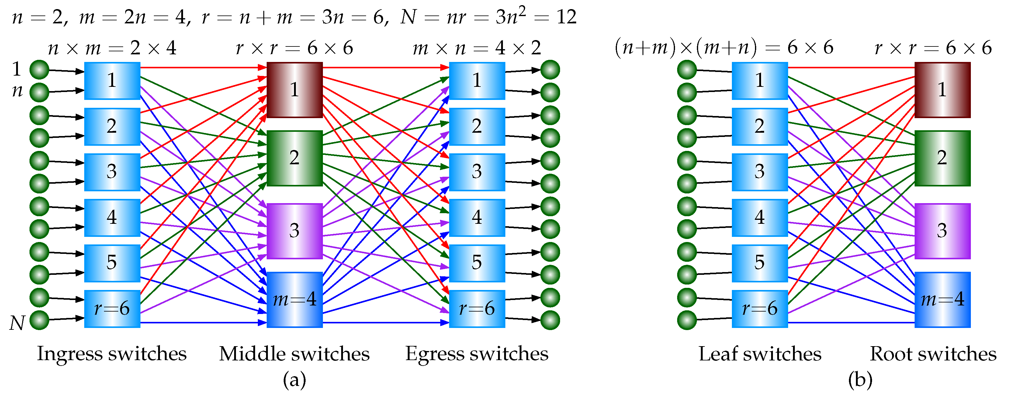
Figure 2.
Merging and expanding an crossbar switch and an crossbar switch to a big square crossbar switch for and . (a) An crossbar switch and an crossbar switch. Each has 8 crosspoints. (b) A square crossbar switch. There are 36 crosspoints. (c) Crosspoint states and implementation using two 2-to-1 multiplexers.
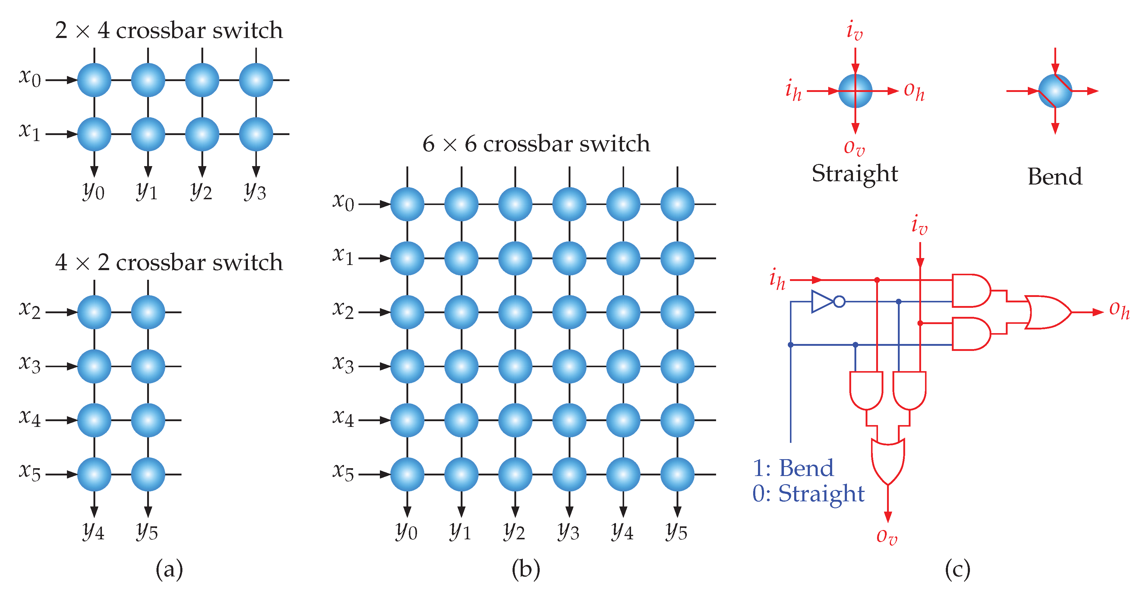
Figure 3.
Proposed strictly nonblocking Clos networks ( and ). (a) A 3-stage USNBC network with , , and . (b) A 2-stage ISNBC network composed of equally sized square crossbars.
Figure 3.
Proposed strictly nonblocking Clos networks ( and ). (a) A 3-stage USNBC network with , , and . (b) A 2-stage ISNBC network composed of equally sized square crossbars.
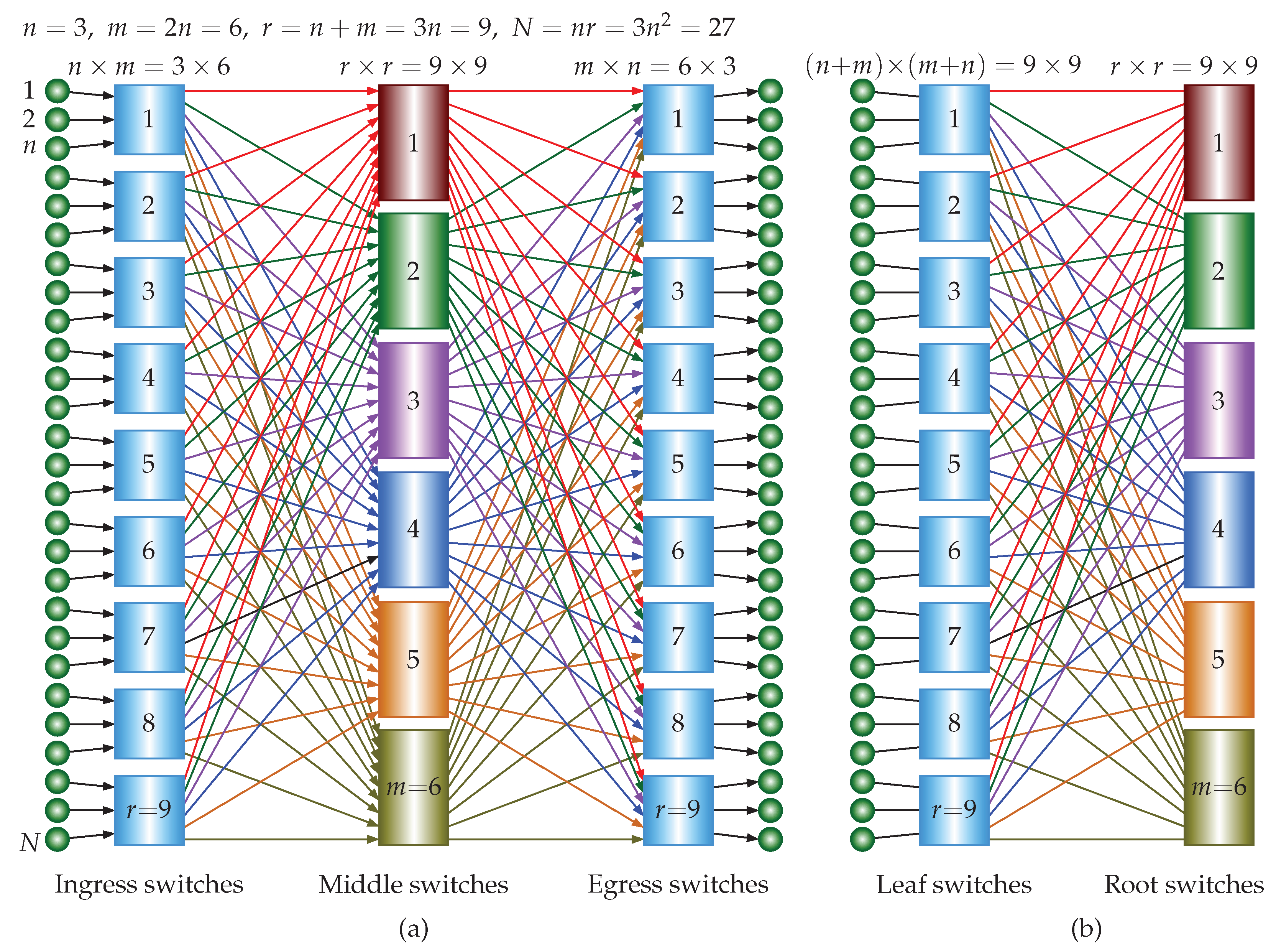
Figure 4.
A 5-stage USNBC network with , , and . There are building blocks (3-stage USNBC, Figure 1(a)) in the middle stage.
Figure 4.
A 5-stage USNBC network with , , and . There are building blocks (3-stage USNBC, Figure 1(a)) in the middle stage.
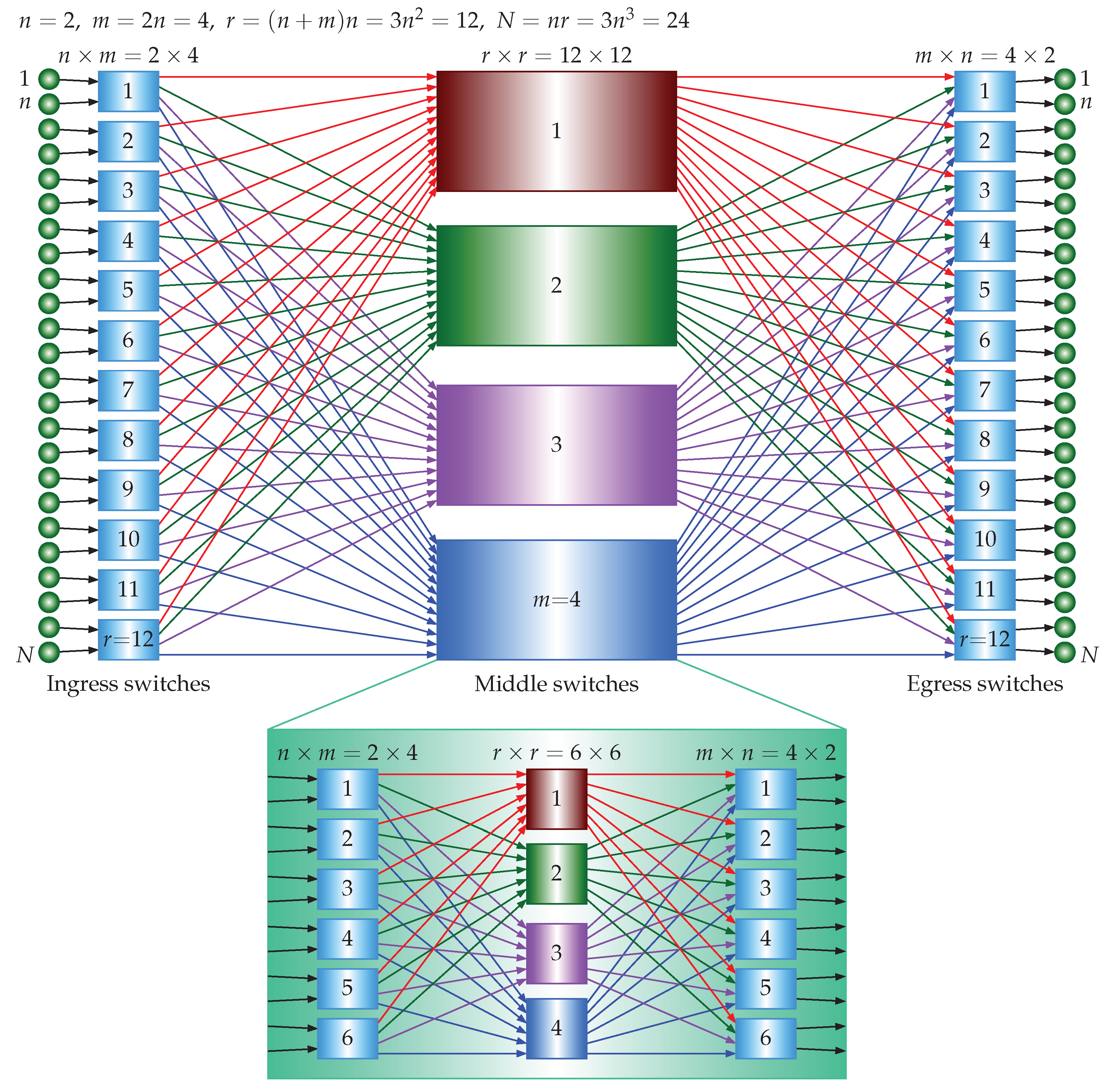
Figure 5.
A 3-stage ISNBC network with composed of equally sized square crossbars (folded version of Figure 4).
Figure 5.
A 3-stage ISNBC network with composed of equally sized square crossbars (folded version of Figure 4).
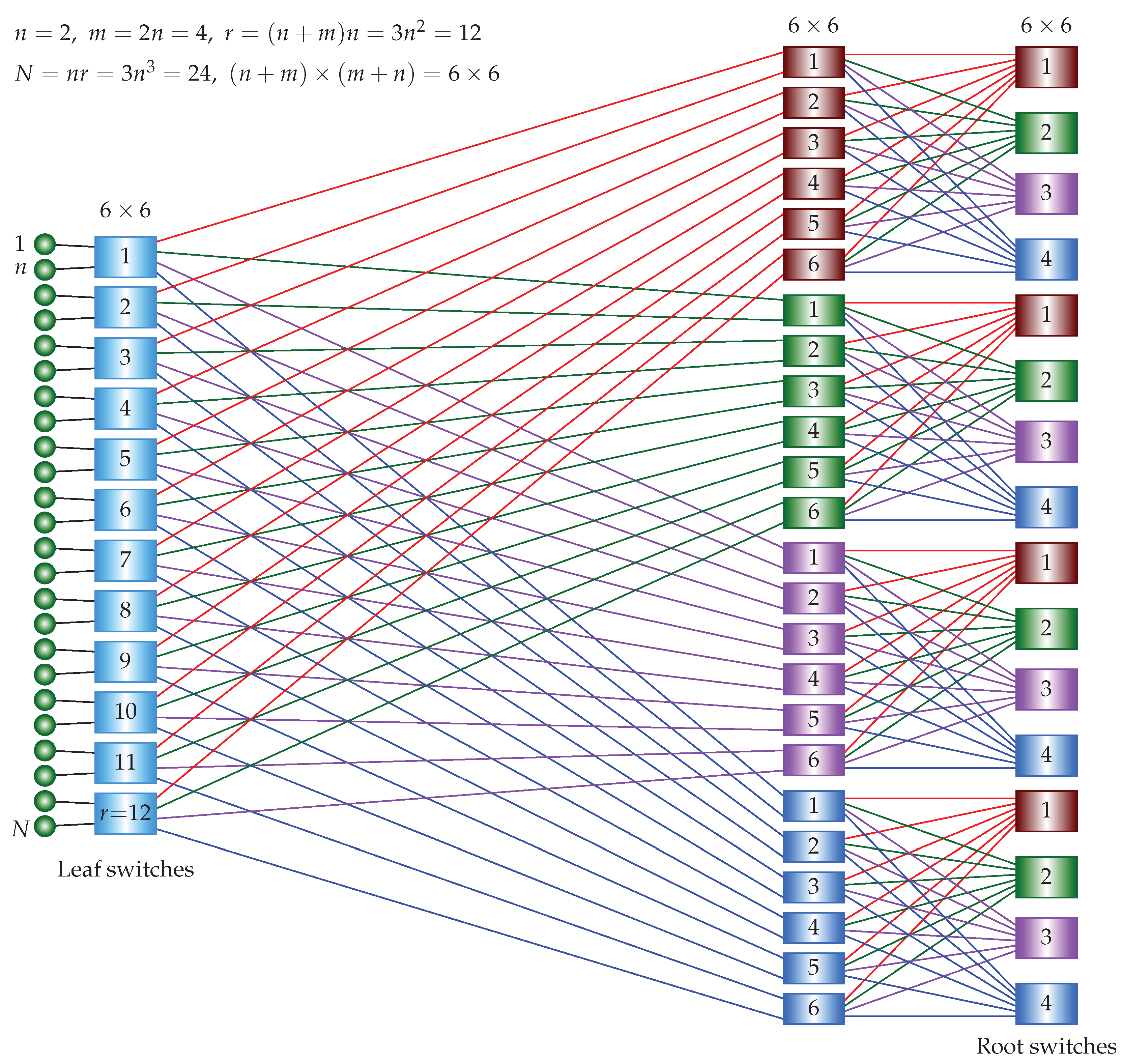
Figure 6.
A 7-stage USNBC network with , , and . There are building blocks (5-stage USNBC, Figure 4) in the middle stage.
Figure 6.
A 7-stage USNBC network with , , and . There are building blocks (5-stage USNBC, Figure 4) in the middle stage.
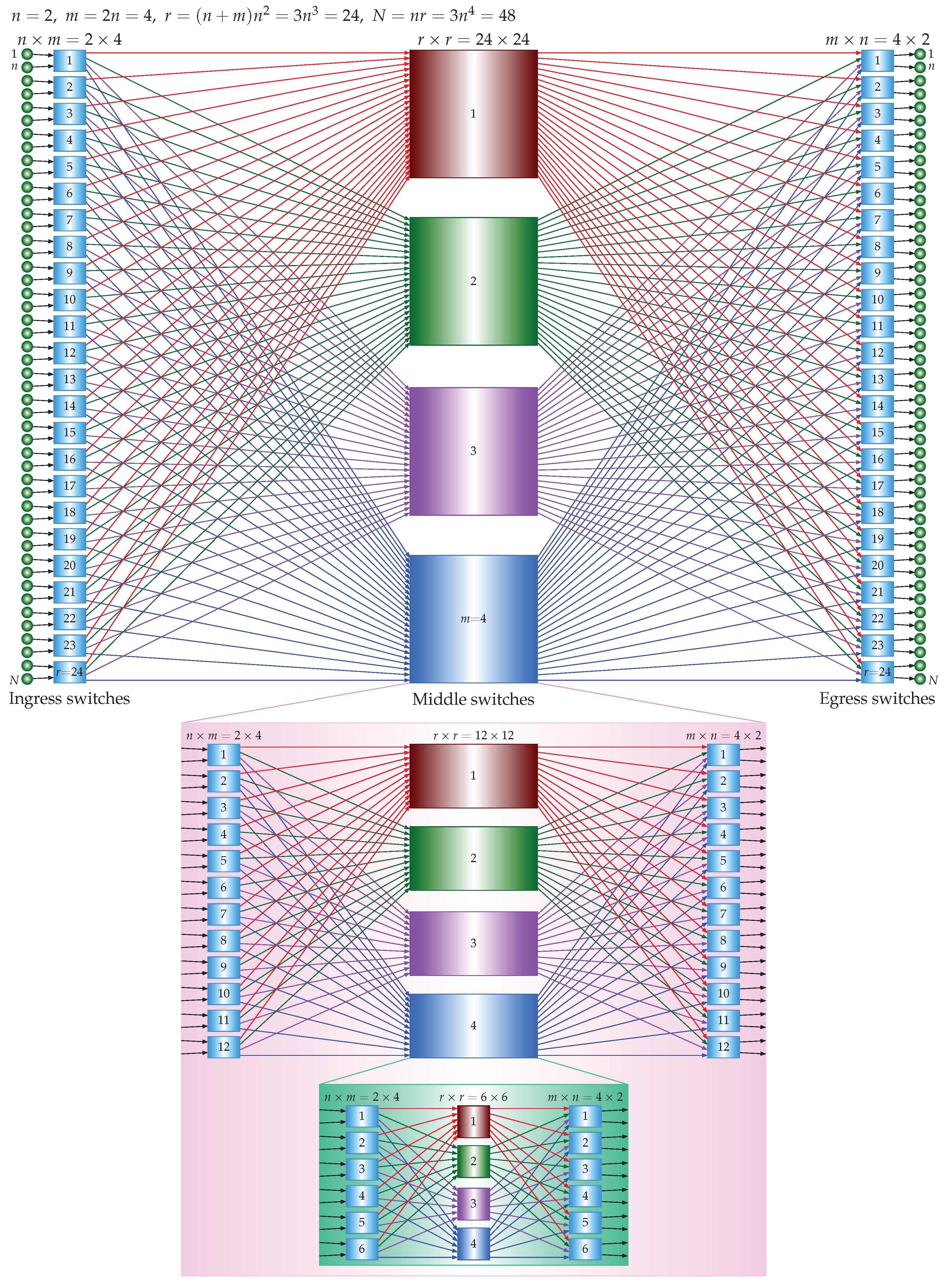
Figure 7.
A 4-stage ISNBC network with composed of equally sized square crossbars (folded version of Figure 6).
Figure 7.
A 4-stage ISNBC network with composed of equally sized square crossbars (folded version of Figure 6).
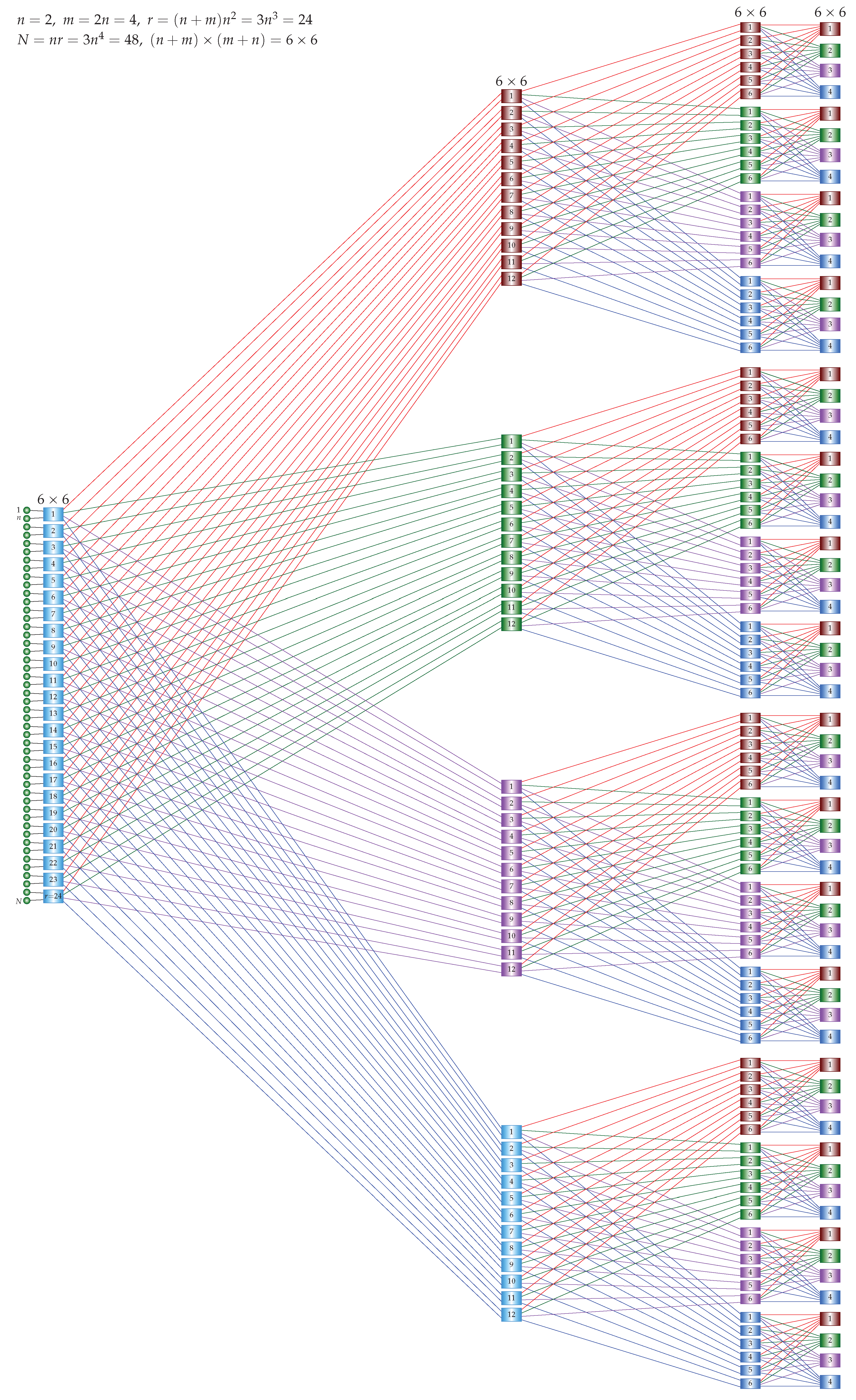
Figure 8.
Proposed rearrangeably nonblocking Clos networks ( and ). (a) A 3-stage URNBC network with , and . (b) A 2-stage IRNBC network composed of equally sized square crossbars.
Figure 8.
Proposed rearrangeably nonblocking Clos networks ( and ). (a) A 3-stage URNBC network with , and . (b) A 2-stage IRNBC network composed of equally sized square crossbars.
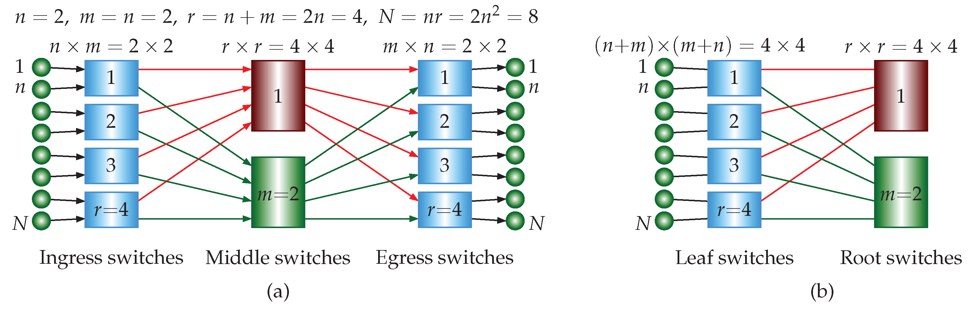
Figure 9.
Blocking and rearrangements in a rearrangeably nonblocking Clos network ( and ). (a) Two connections ( and ) were built. The connection cannot be built. (b) The case of the folded version of (a). Note that a bidirectional link consists of two oppositely oriented unidirectional links. (c) Two connections ( and ) were built. The connection can also be built by the rearrangements of (a). (d) The case of the folded version of (c). (e) Two connections ( and ) were built. The connection can also be built by the rearrangements of (a). (f) The case of the folded version of (e).
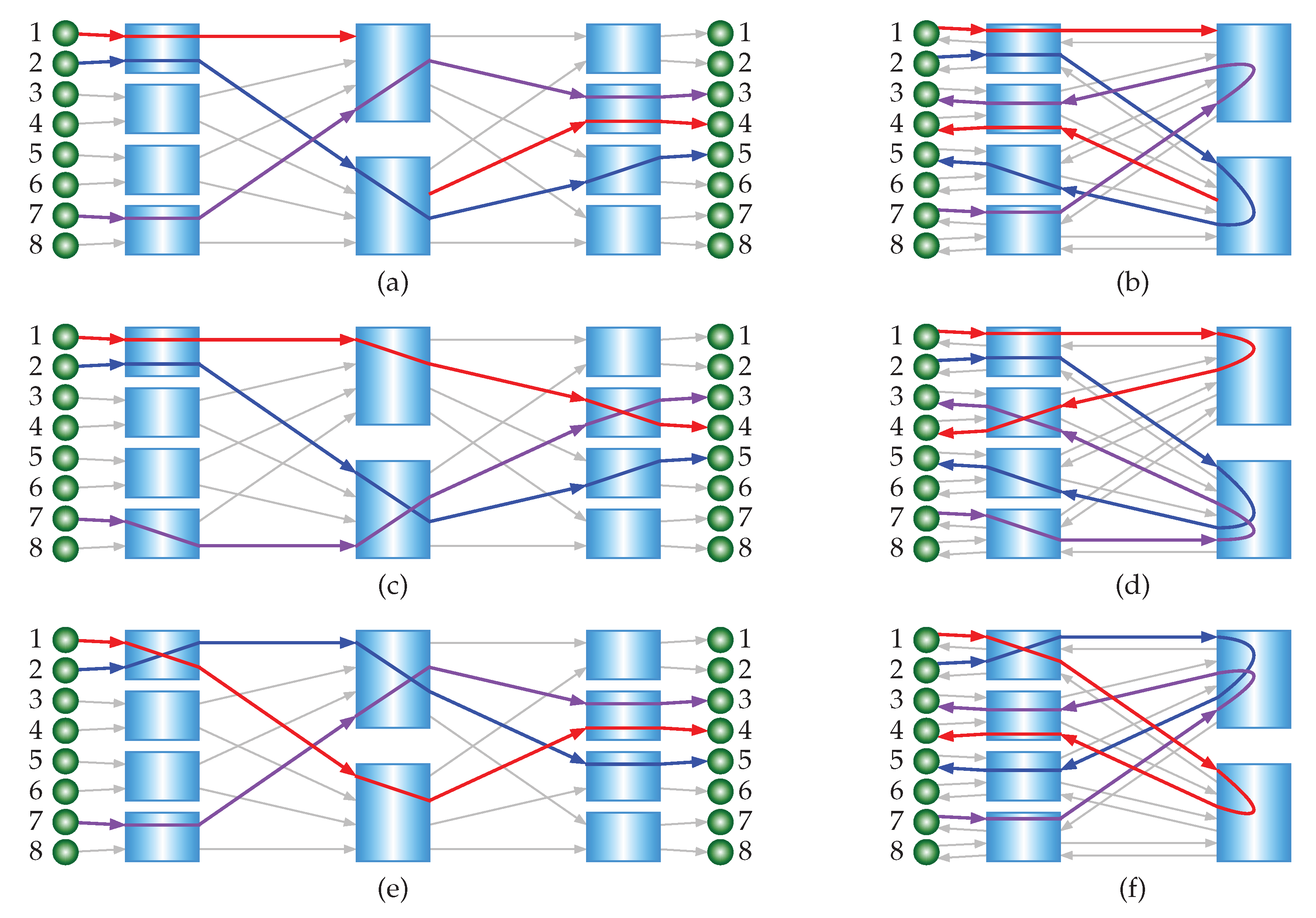
Figure 10.
Proposed rearrangeably nonblocking Clos networks ( and ). (a) A 3-stage URNBC network with , and . (b) A 2-stage IRNBC network composed of equally sized square crossbars.
Figure 10.
Proposed rearrangeably nonblocking Clos networks ( and ). (a) A 3-stage URNBC network with , and . (b) A 2-stage IRNBC network composed of equally sized square crossbars.
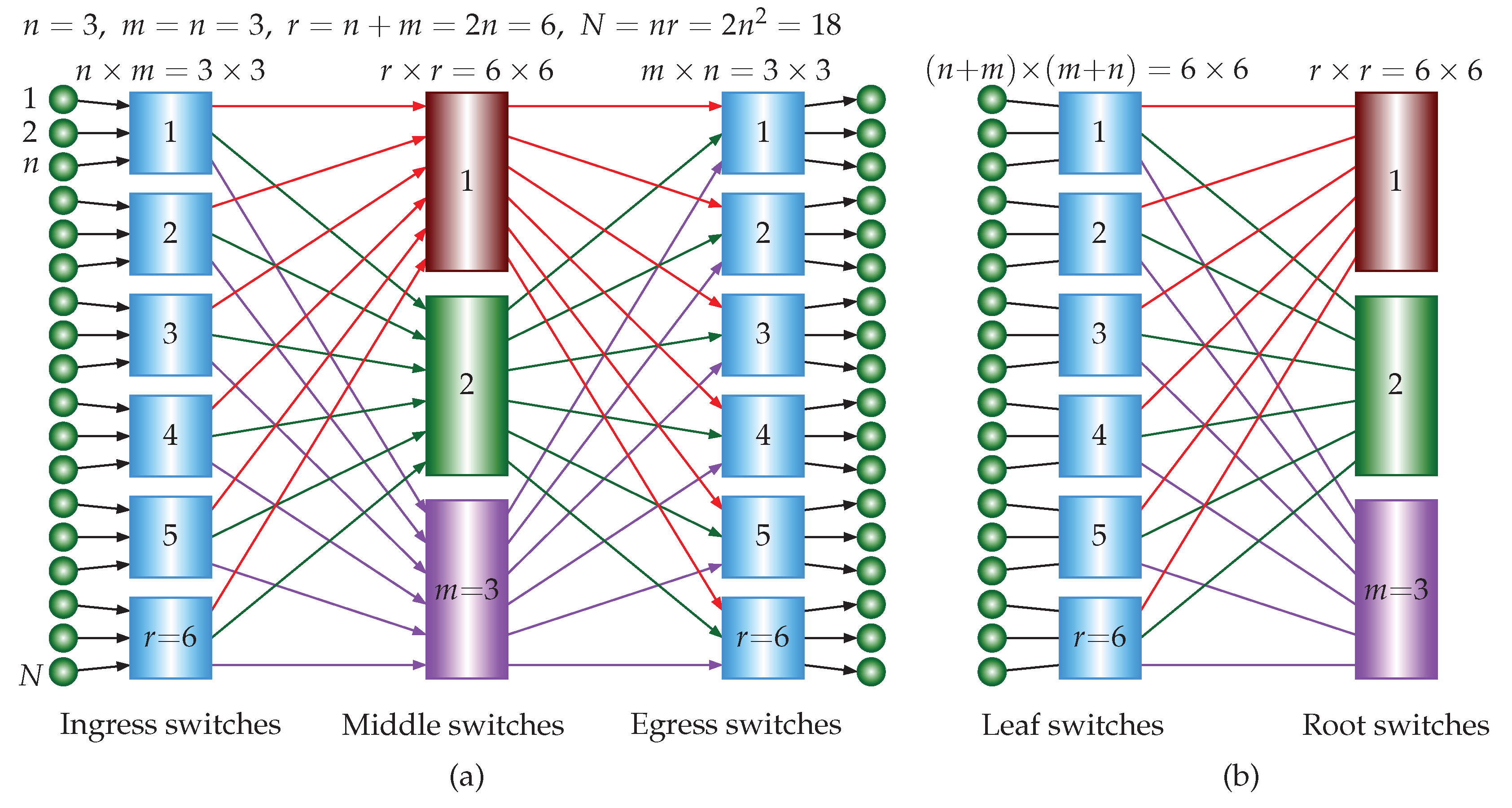
Figure 11.
A 5-stage URNBC network with , , and . There are building blocks (3-stage URNBC, Figure 8(a)) in the middle stage.
Figure 11.
A 5-stage URNBC network with , , and . There are building blocks (3-stage URNBC, Figure 8(a)) in the middle stage.
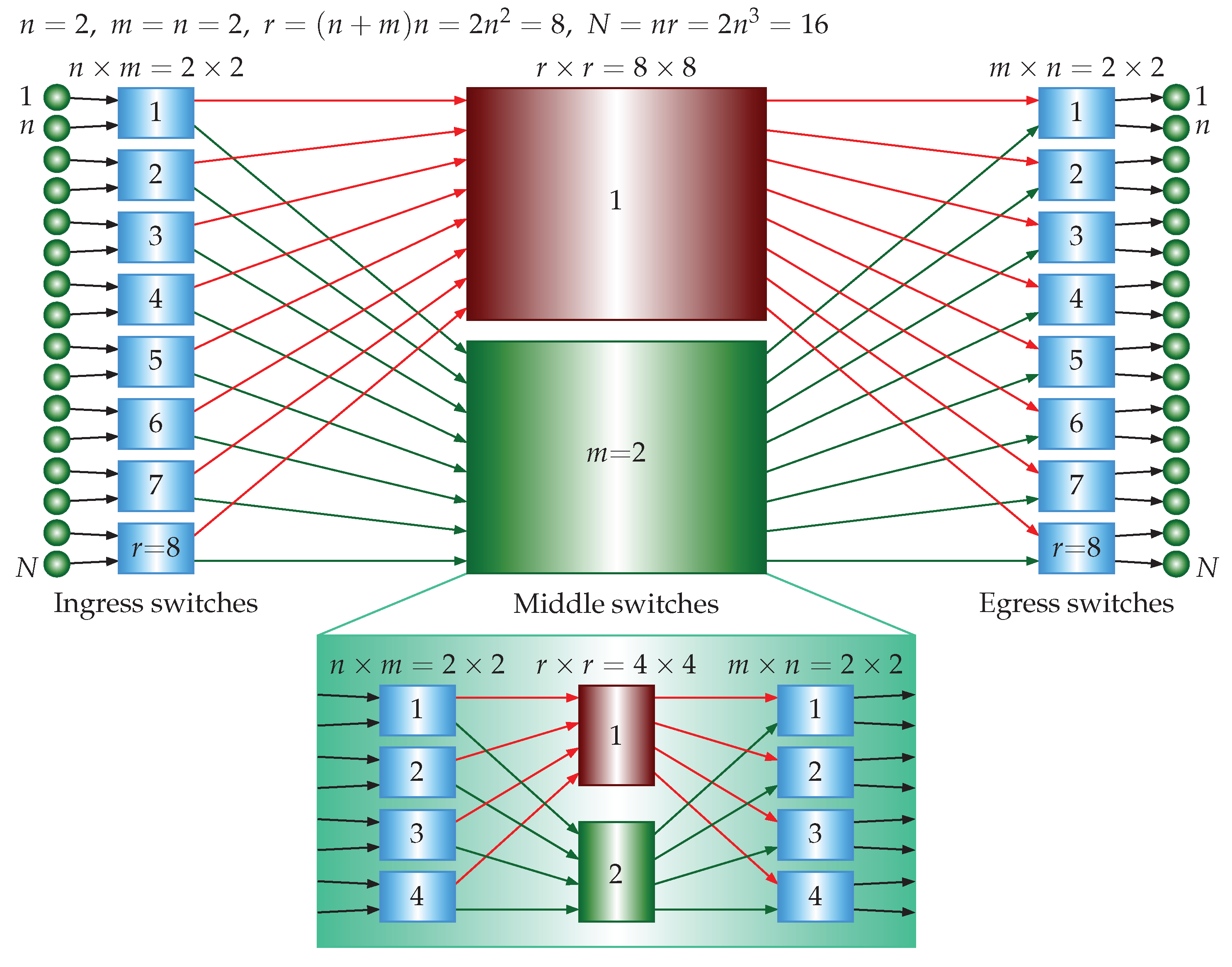
Figure 12.
A 3-stage IRNBC network with composed of equally sized square crossbars (folded version of Figure 11).
Figure 12.
A 3-stage IRNBC network with composed of equally sized square crossbars (folded version of Figure 11).
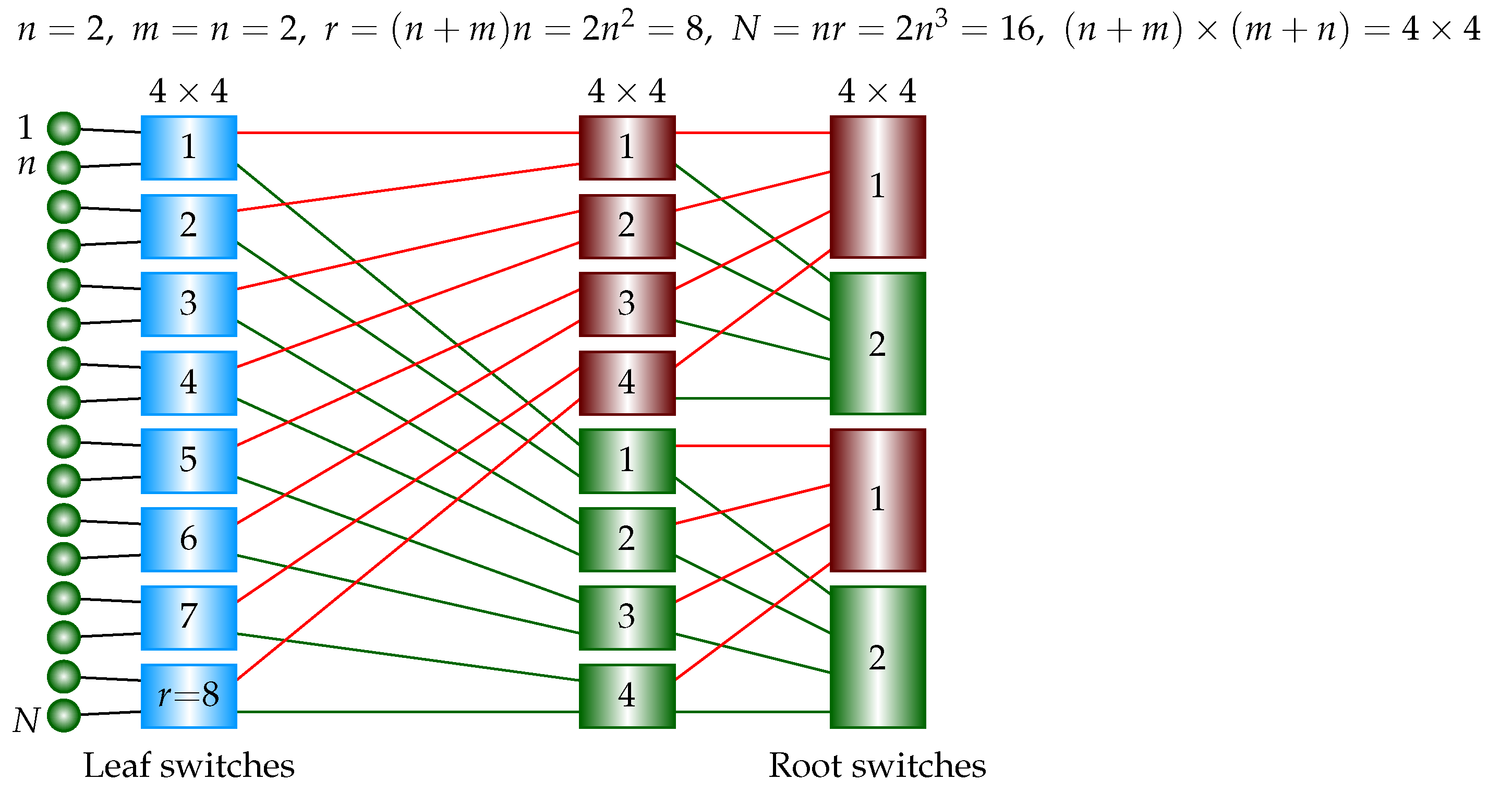
Figure 13.
A 7-stage URNBC network with , , and . There are building blocks (5-stage URNBC, Figure 11) in the middle stage.
Figure 13.
A 7-stage URNBC network with , , and . There are building blocks (5-stage URNBC, Figure 11) in the middle stage.
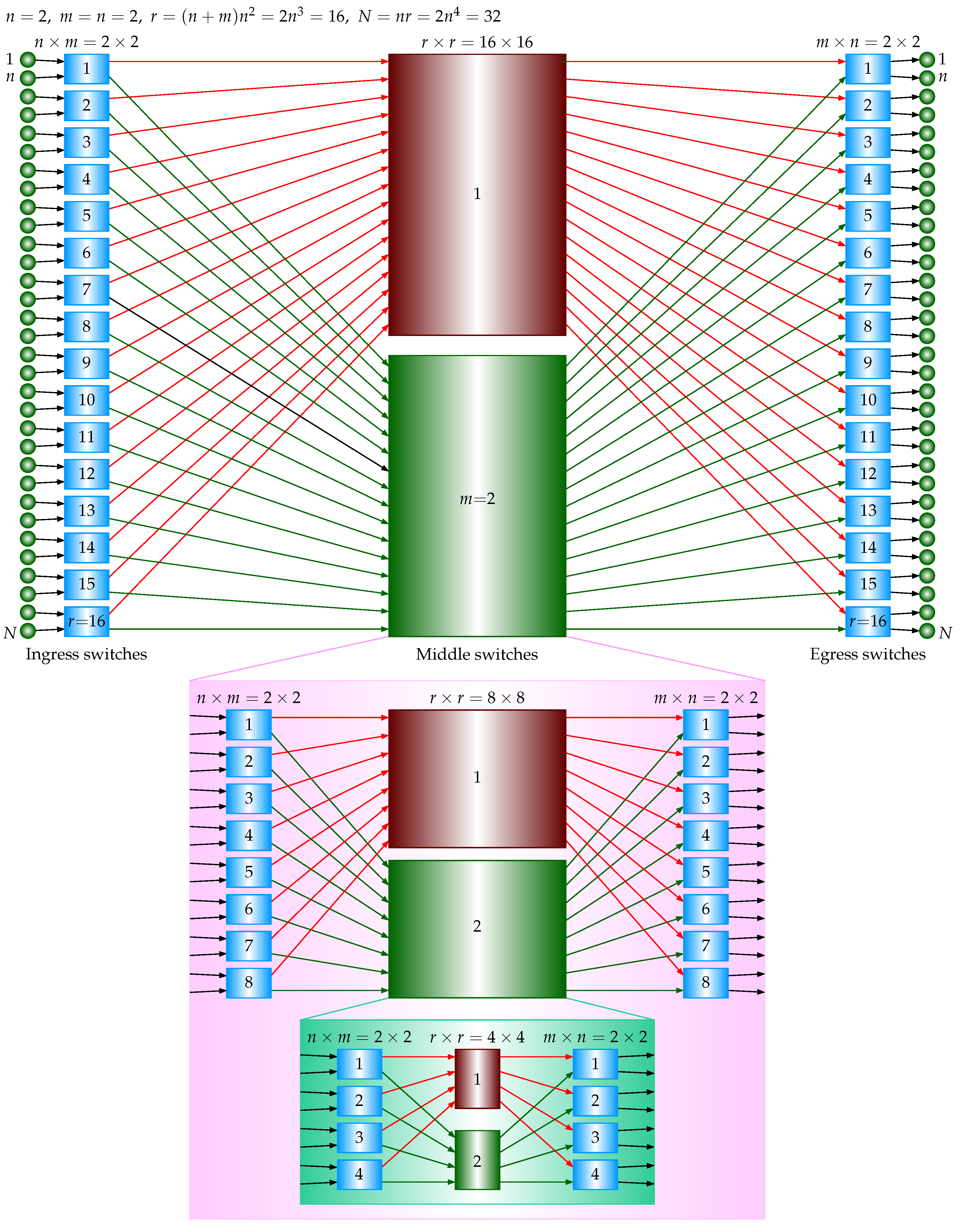
Figure 14.
A 4-stage IRNBC network with composed of equally sized square crossbars (folded version of Figure 13).
Figure 14.
A 4-stage IRNBC network with composed of equally sized square crossbars (folded version of Figure 13).
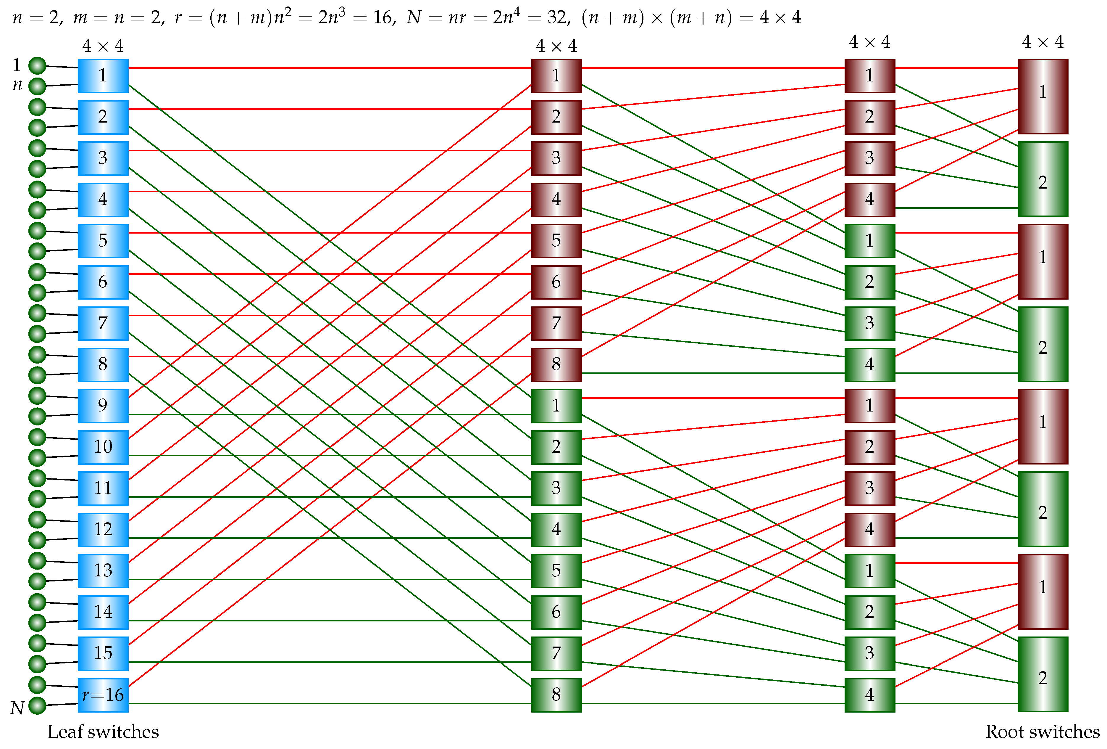
Figure 15.
Crosspoint ratio to the single crossbar in unidirectional strictly nonblocking Clos networks.
Figure 15.
Crosspoint ratio to the single crossbar in unidirectional strictly nonblocking Clos networks.
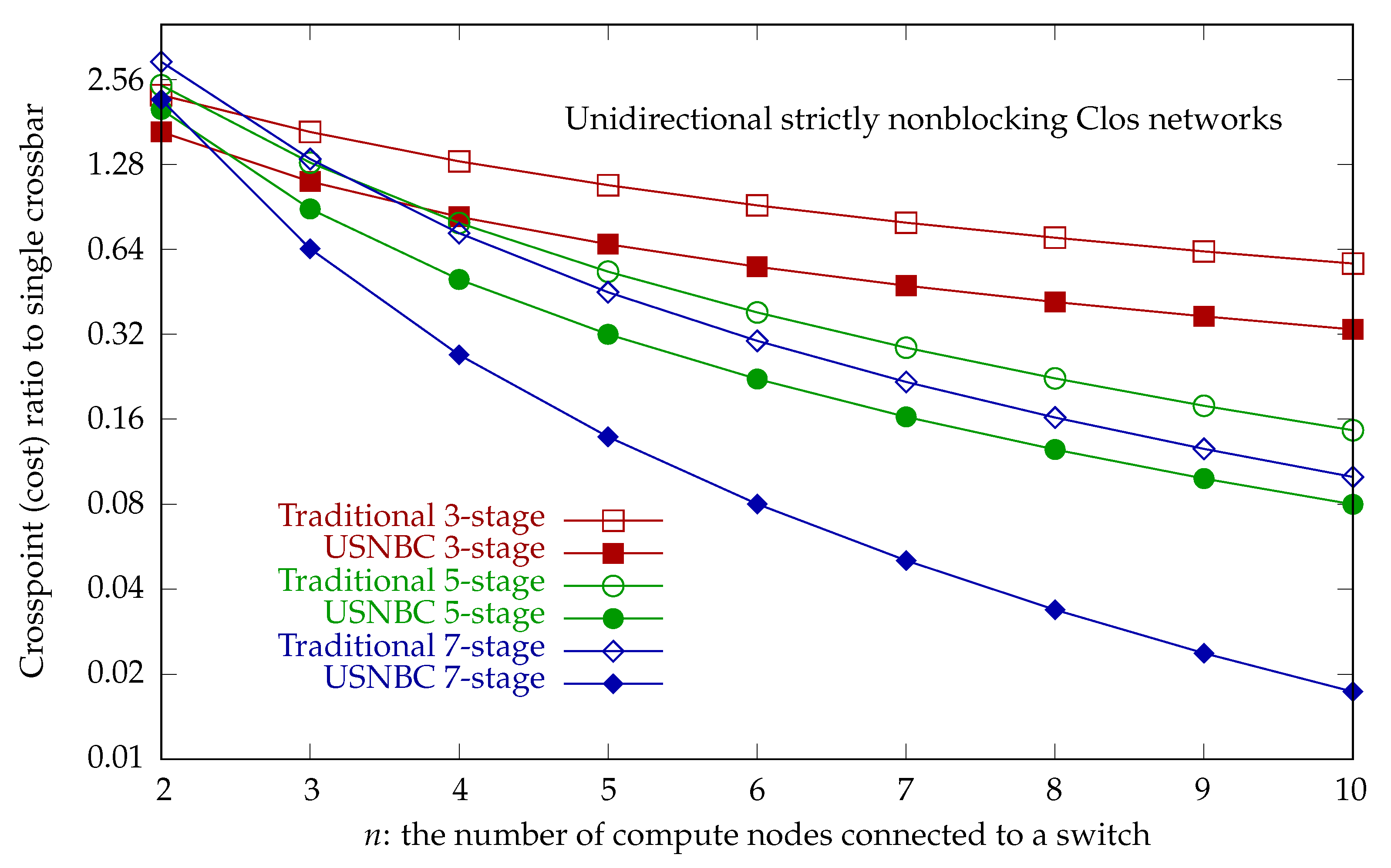
Figure 16.
Crosspoint ratio to the single crossbar in strictly nonblocking folded Clos networks.
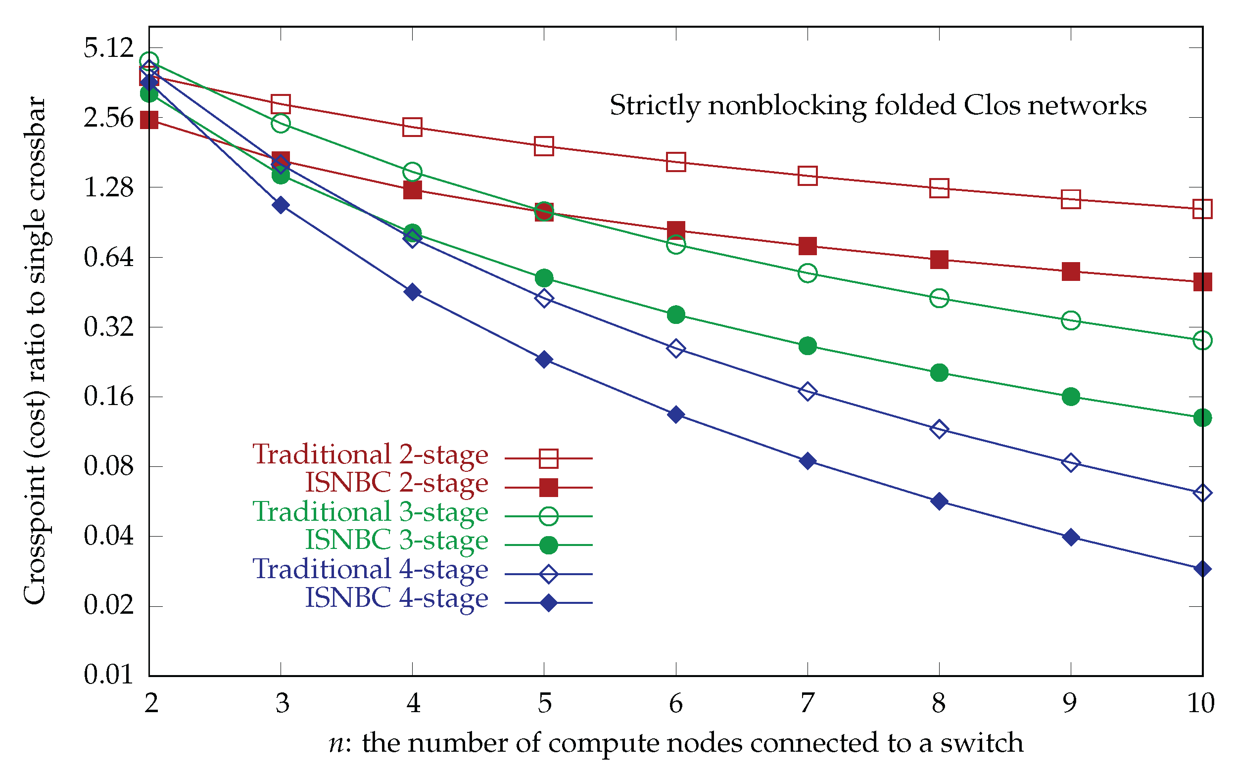
Figure 17.
Crosspoint ratio to the single crossbar in unidirectional rearrangeably nonblocking Clos networks.
Figure 17.
Crosspoint ratio to the single crossbar in unidirectional rearrangeably nonblocking Clos networks.
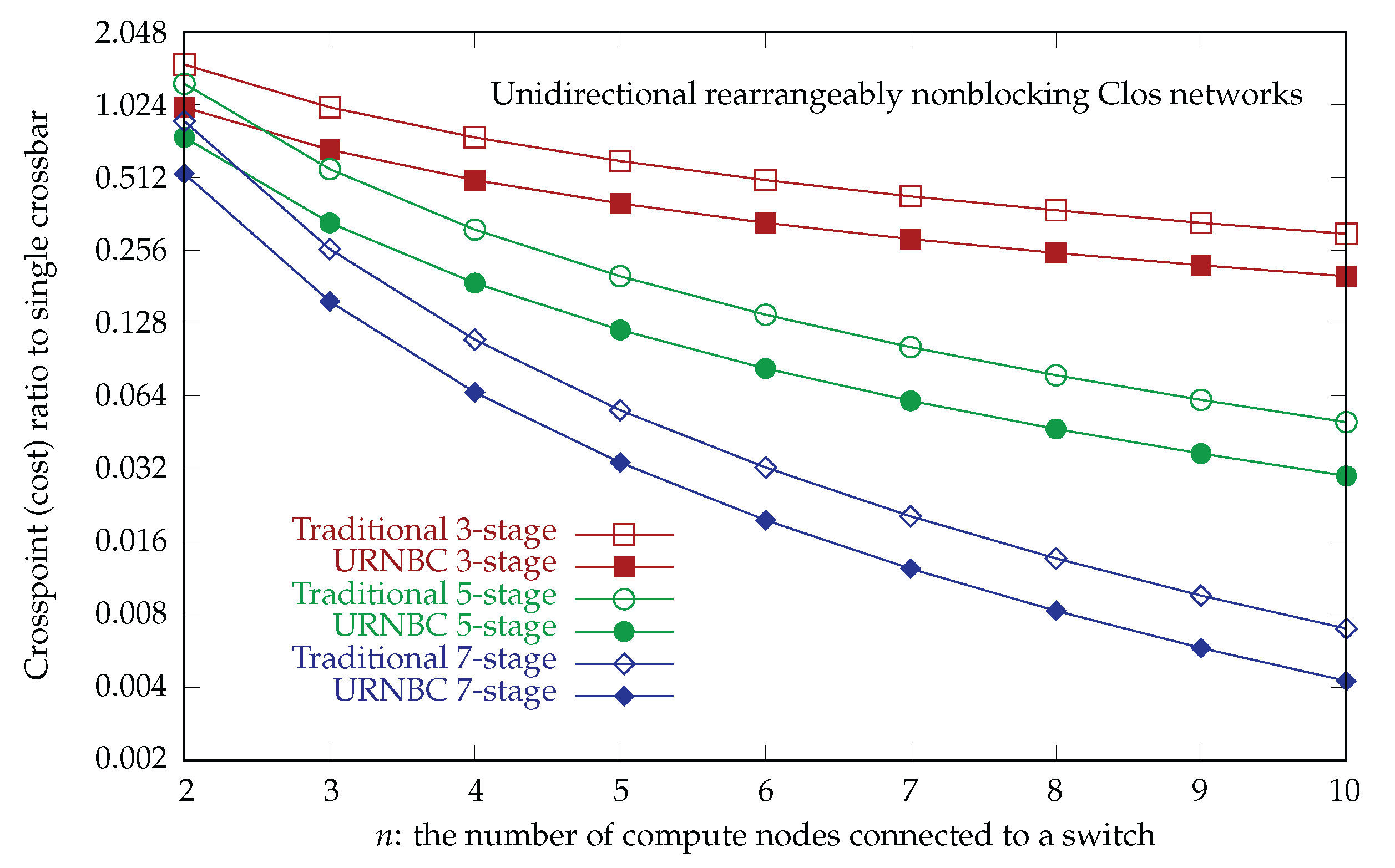
Figure 18.
Crosspoint ratio to the single crossbar in rearrangeably nonblocking folded Clos networks.
Figure 18.
Crosspoint ratio to the single crossbar in rearrangeably nonblocking folded Clos networks.
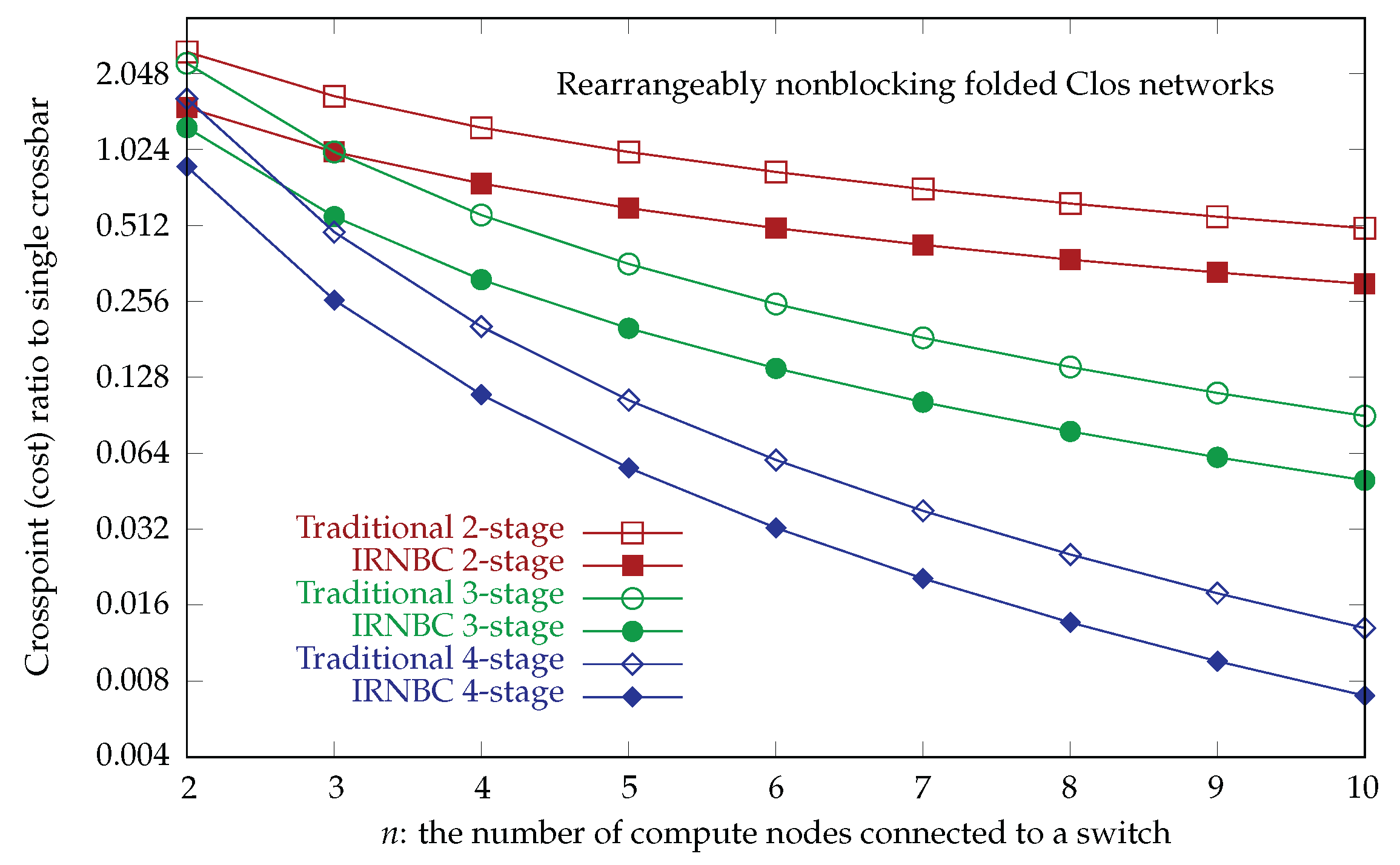
Figure 19.
Crosspoint ratios versus the number of compute nodes in the proposed networks.
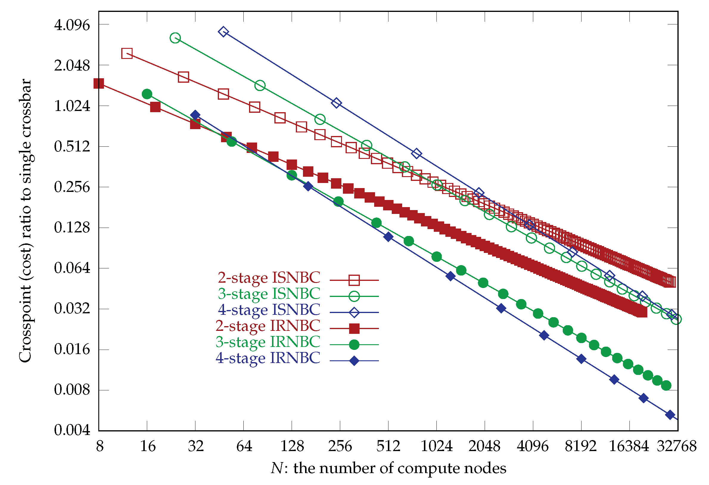

Table 1.
Proposed nonblocking Clos networks.
| Strictly or Rearrangeably | Network | Stage, Unfolded or Folded |
|---|---|---|
| Strictly nonblocking | USNBC | 3-stage, 5-stage, and 7-stage Clos networks |
| ISNBC | 2-stage, 3-stage, and 4-stage folded Clos networks | |
| Rearrangeably nonblocking | URNBC | 3-stage, 5-stage, and 7-stage Clos networks |
| IRNBC | 2-stage, 3-stage, and 4-stage folded Clos networks |
Table 2.
The numbers of compute nodes and switches in the ISNBC networks.
| Number of compute nodes | Number of switches | ||||||
|---|---|---|---|---|---|---|---|
| 2-stage | 3-stage | 4-stage | 2-stage | 3-stage | 4-stage | Crossbar | |
| 2 | 12 | 24 | 48 | 10 | 52 | 232 | |
| 3 | 27 | 81 | 243 | 15 | 117 | 783 | |
| 4 | 48 | 192 | 768 | 20 | 208 | 1856 | |
| 5 | 75 | 375 | 1875 | 25 | 325 | 3625 | |
| 6 | 108 | 648 | 3888 | 30 | 468 | 6264 | |
| 7 | 147 | 1029 | 7203 | 35 | 637 | 9947 | |
| 8 | 192 | 1536 | 12,288 | 40 | 832 | 14,848 | |
| 9 | 243 | 2187 | 19,683 | 45 | 1053 | 21,141 | |
| 10 | 300 | 3000 | 30,000 | 50 | 1300 | 29,000 | |
Table 3.
The numbers of compute nodes and switches in the IRNBC networks.
| Number of compute nodes | Number of switches | ||||||
|---|---|---|---|---|---|---|---|
| 2-stage | 3-stage | 4-stage | 2-stage | 3-stage | 4-stage | Crossbar | |
| 2 | 8 | 16 | 32 | 6 | 20 | 56 | |
| 3 | 18 | 54 | 162 | 9 | 45 | 189 | |
| 4 | 32 | 128 | 512 | 12 | 80 | 448 | |
| 5 | 50 | 250 | 1250 | 15 | 125 | 875 | |
| 6 | 72 | 432 | 2592 | 18 | 180 | 1512 | |
| 7 | 98 | 686 | 4802 | 21 | 245 | 2401 | |
| 8 | 128 | 1024 | 8192 | 24 | 320 | 3584 | |
| 9 | 162 | 1458 | 13,122 | 27 | 405 | 5103 | |
| 10 | 200 | 2000 | 20,000 | 30 | 500 | 7000 | |
| 11 | 242 | 2662 | 29,282 | 33 | 605 | 9317 | |
| 12 | 288 | 3456 | 41,472 | 36 | 720 | 12,096 | |
| 13 | 338 | 4394 | 57,122 | 39 | 845 | 15,379 | |
| 14 | 392 | 5488 | 76,832 | 42 | 980 | 19,208 | |
| 15 | 450 | 6750 | 101,250 | 45 | 1125 | 23,625 | |
Table 4.
Nonblocking Clos networks for cost evaluations.
| Stric or Rearr | Unidir or Bidir | Network | Stage, Unfolded or Folded |
| Strictly nonblocking | Unidirectional | USNBC | 3-, 5-, and 7-stage Clos networks |
| Traditional | 3-, 5-, and 7-stage Clos networks | ||
| Bidirectional | ISNBC | 2-, 3-, and 4-stage folded Clos networks | |
| Traditional | 2-, 3-, and 4-stage folded Clos networks | ||
| Rearrangeably nonblocking | Unidirectional | URNBC | 3-, 5-, and 7-stage Clos networks |
| Traditional | 3-, 5-, and 7-stage Clos networks | ||
| Bidirectional | IRNBC | 2-, 3-, and 4-stage folded Clos networks | |
| Traditional | 2-, 3-, and 4-stage folded Clos networks |
Table 5.
Crosspoint ratio for unidirectional strictly nonblocking Clos networks.
| Network | 3-stage | 5-stage | 7-stage |
|---|---|---|---|
| Traditional | − | −− | (−+− |
| USNBC |
Table 6.
The number of crosspoints in the ISNBC networks.
| 2-stage | 3-stage | 4-stage | |||||||
|---|---|---|---|---|---|---|---|---|---|
| Node | Crossbar | ISNBC | Node | Crossbar | ISNBC | Node | Crossbar | ISNBC | |
| 2 | 12 | 144 | 360 | 24 | 576 | 1872 | 48 | 2304 | 8352 |
| 3 | 27 | 729 | 1215 | 81 | 6561 | 9477 | 243 | 59,049 | 63,423 |
| 4 | 48 | 2304 | 2880 | 192 | 36,864 | 29,952 | 768 | 589,824 | 267,264 |
| 5 | 75 | 5625 | 5625 | 375 | 140,625 | 73,125 | 1875 | 3,515,625 | 815,625 |
| 6 | 108 | 11,664 | 9720 | 648 | 419,904 | 151,632 | 3888 | 15,116,544 | 2,029,536 |
| 7 | 147 | 21,609 | 15,435 | 1029 | 1,058,841 | 280,917 | 7203 | 51,883,209 | 4,386,627 |
| 8 | 192 | 36,864 | 23,040 | 1536 | 2,359,296 | 479,232 | 12,288 | 150,994,944 | 8,552,448 |
| 9 | 243 | 59,049 | 32,805 | 2187 | 4,782,969 | 767,637 | 19,683 | 387,420,489 | 15,411,789 |
| 10 | 300 | 90,000 | 45,000 | 3000 | 9,000,000 | 1,170,000 | 30,000 | 900,000,000 | 26,100,000 |
Table 7.
Crosspoint ratio for strictly nonblocking folded Clos networks.
| Network | 2-stage | 3-stage | 4-stage |
|---|---|---|---|
| Traditional | −+ | −+− | −+−+ |
| ISNBC |
Table 8.
Crosspoint ratio for unidirectional rearrangeably nonblocking Clos networks.
| Network | 3-stage | 5-stage | 7-stage |
|---|---|---|---|
| Traditional | |||
| URNBC | |||
| URNBC/Traditional |
Table 9.
The number of crosspoints in the IRNBC networks.
| 2-stage | 3-stage | 4-stage | |||||||
|---|---|---|---|---|---|---|---|---|---|
| Node | Crossbar | IRNBC | Node | Crossbar | IRNBC | Node | Crossbar | IRNBC | |
| 2 | 8 | 64 | 96 | 16 | 256 | 320 | 32 | 1024 | 896 |
| 3 | 18 | 324 | 324 | 54 | 2916 | 1620 | 162 | 26,244 | 6804 |
| 4 | 32 | 1024 | 768 | 128 | 16,384 | 5120 | 512 | 262,144 | 28,672 |
| 5 | 50 | 2500 | 1500 | 250 | 62,500 | 12,500 | 1250 | 1,562,500 | 87,500 |
| 6 | 72 | 5184 | 2592 | 432 | 186,624 | 25,920 | 2592 | 6,718,464 | 217,728 |
| 7 | 98 | 9604 | 4116 | 686 | 470,596 | 48,020 | 4802 | 23,059,204 | 470,596 |
| 8 | 128 | 16,384 | 6144 | 1024 | 1,048,576 | 81,920 | 8192 | 67,108,864 | 917,504 |
| 9 | 162 | 26,244 | 8748 | 1458 | 2,125,764 | 131,220 | 13,122 | 172,186,884 | 1,653,372 |
| 10 | 200 | 40,000 | 12,000 | 2000 | 4,000,000 | 200,000 | 20,000 | 400,000,000 | 2,800,000 |
Table 10.
Crosspoint ratio for rearrangeably nonblocking folded Clos networks.
| Network | 2-stage | 3-stage | 4-stage |
|---|---|---|---|
| Traditional | |||
| IRNBC | |||
| IRNBC/Traditional |
Table 11.
Summary of the proposed ISNBC and IRNBC networks where n is the number of compute nodes connected to a leaf switch and s is the number of stages.
Table 11.
Summary of the proposed ISNBC and IRNBC networks where n is the number of compute nodes connected to a leaf switch and s is the number of stages.
| Network | Node | Crossbar | Crosspoint | Switch | Switch size |
|---|---|---|---|---|---|
| ISNBC | |||||
| IRNBC |
Disclaimer/Publisher’s Note: The statements, opinions and data contained in all publications are solely those of the individual author(s) and contributor(s) and not of MDPI and/or the editor(s). MDPI and/or the editor(s) disclaim responsibility for any injury to people or property resulting from any ideas, methods, instructions or products referred to in the content. |
© 2025 by the authors. Licensee MDPI, Basel, Switzerland. This article is an open access article distributed under the terms and conditions of the Creative Commons Attribution (CC BY) license (http://creativecommons.org/licenses/by/4.0/).
Copyright: This open access article is published under a Creative Commons CC BY 4.0 license, which permit the free download, distribution, and reuse, provided that the author and preprint are cited in any reuse.


