
Submitted:
28 May 2025
Posted:
29 May 2025
You are already at the latest version
Abstract
The Flexible Combined Imager (FCI), developed as the next-generation imager for the European Organisation for the Exploitation of Meteorological Satellites (EUMETSAT) Meteosat Third Generation (MTG) satellite series, represents a significant advancement over its predecessor, SEVIRI, on the Meteosat Second Generation (MSG) satellites. FCI offers more spectral bands, higher spatial resolution, and faster imaging capabilities, supporting a wide range of applications in weather forecasting, climate monitoring, and environmental analysis. On 13 January 2024, the FCI onboard MTG-I1 (renamed Meteosat-12 in December 2024) experienced a critical anomaly involving the failure of its onboard Calibration and Obturation Mechanism (COM). As a result, the use of the COM was discontinued to preserve operational safety, leaving the instrument dependent on alternative calibration methods. This loss of onboard calibration presents immediate challenges, particularly for the infrared channels, including image artifacts (e.g., striping), reduced radiometric accuracy, and diminished stability. To address these issues, EUMETSAT implemented an external calibration approach leveraging algorithms from the Global Space-based Inter-Calibration System (GSICS). The inter-calibration algorithm transfers stable and accurate calibration from the Infrared Atmospheric Sounding Interferometer (IASI) hyperspectral instrument aboard Metop-B and Metop-C satellites to FCI’s infrared channels daily, ensuring continued data quality. Comparisons with Cross-track Infrared Sounder (CrIS) data from NOAA-20 and NOAA-21 satellites using a similar algorithm is then used to validate the radiometric performance of the calibration. This confirms that the external calibration method effectively compensates for the absence of onboard blackbody calibration for the infrared channels. For the visible and near-infrared channels, slower degradation rates and pre-anomaly calibration ensure continued accuracy, with vicarious calibration expected to become the primary source. This adaptive calibration strategy introduces a novel paradigm for in-flight calibration of geostationary instruments and offers valuable insights for satellite missions lacking onboard calibration devices. This paper details the COM anomaly, the external calibration process, and the broader implications for future geostationary satellite missions.
Keywords:
flexible combined imager (FCI)
; meteosat third generation (MTG)
; COM anomaly
; GSICS
; MICMICS
; inter-calibration
; vicarious calibration
1. Introduction
Accurate satellite measurements are essential for understanding the environment and enabling a wide range of applications, from real-time weather forecasting to long-term climate monitoring and environmental analysis [1,2]. Ensuring accurate and reliable data from satellite instruments requires that they remain well-calibrated throughout their operational lifetimes in orbit. Although instruments undergo thorough ground calibration before launch, exposure to launch conditions and the harsh environment of space often leads to performance degradation over time [3]. Therefore, rigorous and continuous monitoring of radiometric performance is critical during their lifespan in orbit.
Onboard calibration devices play a vital role in maintaining radiometric performance for infrared (IR) and reflective solar channels. These systems perform regular calibration checks using blackbody references for IR channels and solar diffusers or metallic neutral density filters for reflective solar channels [4]. However, onboard calibration devices themselves are subject to gradual degradation, necessitating additional measures to ensure long-term accuracy [3].
For instruments without onboard calibration devices, vicarious calibration and inter-calibration techniques are employed to track and correct performance. These techniques are not only crucial for such instruments but also play a key role in validating and correcting the onboard calibration devices in case of performance degradation. Vicarious and inter-calibration methods have been widely used for decades to monitor and adjust instrument performance for both IR and reflective solar channels [5,6,7,8,9,10]. Infrared channels are particularly vulnerable to degradation from factors such as ice contamination and sensor technology limitations, requiring more frequent calibration than reflective solar channels [11]. Thus, the integration of onboard calibration systems, complemented by robust framework for vicarious calibration and inter-calibration is essential to maintain the accuracy and reliability of satellite measurements throughout the instrument's operational life.
EUMETSAT has operated geostationary weather satellites for decades, deploying three successive generations of geostationary (GEO) satellite systems to enhance meteorological observation and forecasting. The first satellite in the Meteosat Third Generation (MTG) series, developed through collaboration between EUMETSAT and the European Space Agency (ESA) and launched on 13 December 2022, represents a major step forward, carrying two advanced instruments; the Flexible Combined Imager (FCI) and the Lightning Imager (LI) [12]. The FCI, developed as the next-generation imaging system, builds upon and surpasses the capabilities of SEVIRI instrument, aboard the Meteosat Second Generation (MSG) satellites [13,14]. Offering increased spectral coverage, finer spatial resolution, and more rapid image acquisition, the FCI plays a critical role in supporting applications like weather forecasting, climate monitoring, and environmental analysis. Complementing the FCI, the Lightning Imager (LI) provides continuous monitoring of lightning activity across Europe, Africa, and surrounding regions, significantly enhancing severe weather detection and early warning systems [15]. The FCI payload was developed by Thales Alenia Space in France who are also the industrial Prime Contractor for the Space segment of MTG.
The in-orbit calibration of the FCI’s infrared (IR) and visible and near-infrared (VNIR) channels is nominally enabled by a blackbody and Metallic Neutral Density (MND) filters, respectively. These components are mounted on the Calibration and Obturation Mechanism (COM), which, during nominal operations, is regularly inserted into the optical path to perform regular calibration.
On 13 January 2024, during satellite commissioning, the FCI experienced a critical anomaly in the COM, resulting in the complete loss of onboard calibration sources for both the visible and infrared channels [16].
To ensure operational safety, the use of the COM was discontinued, leaving the instrument reliant on external calibration methods. This paper outlines the external calibration strategies implemented to replace onboard calibration, addressing the absence of blackbody references for IR channels and MND filters for reflective solar channels.
2. COM Anomaly and Its Impact
The Calibration and Obturation Mechanism for the FCI instrument (COM-I), depicted in Figure 1, is a critical component responsible for managing optical source selection across the instrument’s operational modes. These include Earth observation ("free-beam"), calibration, and protective obturation ("shutter"). The COM achieves this by inserting specific optical elements into the optical path. IR calibration relies on a blackbody as a controlled radiance source, supported by high-accuracy thermometry, enabling calibration at two distinct temperature levels. For VNIR channels, calibration is facilitated by MND filters, which can be placed into the optical path while imaging the Sun.
In addition to calibration functions, the COM is instrumental in operations requiring the "shutter" state, such as satellite manoeuvres or instrument reconfigurations, where it is critical to return the COM to the "free-beam" position once the operation concludes. Furthermore, the COM serves as a safeguard, enabling the instrument to transition to a "shutter" configuration during anomalies. To minimize risk following the COM anomaly, ongoing reviews aim to restrict the activation of the "shutter" position to anomalies posing a direct threat to the optical path.
Following the deactivation of the COM, the FCI instrument lost its primary onboard calibration sources for both IR and VNIR channels. The IR channels are particularly affected due to their sensitivity to temporal changes. IR calibration was originally planned to occur every 10 minutes, coinciding with the “retrace” phase of nominal scan patterns (Figure 2). By viewing the blackbody and leveraging its known temperature and high emissivity, accurate calibrations ensured compliance with end-user requirements.
Investigations into the anomaly revealed that such frequent blackbody measurements were not strictly necessary. The sensor demonstrated sufficient in-orbit stability to require calibration only a few times per day. However, without blackbody calibration to compensate for response variations caused by optical elements and the contaminants building up on the cryostat detectors, the instrument exhibits a drift in measured brightness temperatures, with errors significantly exceeding user requirements for the absolute radiometric accuracy (<0.7 K) in the 10.5, 12.3, and 13.3 µm channels. Other IR channels show slower drifts because of less sensitivity to contaminants (mainly water ice, but not limited to it). An example of computed evolution of the 12.3 µm channel in the absence of blackbody calibration shows that, in the worst-case scenario, brightness temperatures (Tb) can drift up to 2 K/month for this channel. This degradation presents immediate challenges, reduced absolute radiometric accuracy, and diminished radiometric stability.
In contrast to the IR channels, the VNIR channels remain reliably characterized due to their slower degradation rates. The MND filter for VNIR calibration is housed within the COM wheel (Figure 1). This filter enables VNIR channel calibration by observing the Sun as a reference, a process conducted two times per year. This periodic calibration compensates for degradation in VNIR channels. Prior to the COM failure, a complete MND calibration cycle confirmed the consistency of VNIR channels’ calibration when compared to on-ground characterizations. This reliability enables VNIR data production based on initial characterizations.
Despite their current stability, the long-term operation of the VNIR channels requires continuous monitoring and the development of alternative calibration methods to address potential degradation. Although degradation is slower, it can still accumulate over time, making proactive measures essential.
3. External Calibration Approach
Before FCI was brought again into operation on 23 May 2024, the entire onboard calibration procedure had to be redesigned using an offline and indirect methodology. This approach leverages nominal deep-space acquisitions to calculate offsets and employs an external calibration source to determine gains.
Figure 3 presents the external calibration flowchart, outlining the steps involved in generating gains and applying them to produce synthetically calibrated Level-1C (L1C) FCI data. The process begins with EUMETSAT Mission-Integrated Calibration Monitoring and Intercalibration System (MICMICS), which generates daily average IR gains per channel using data from the IASI aboard the Metop-B and Metop-C satellites. These estimated gains undergo rigorous quality checks, including comparisons against data from NOAA-20 and NOAA-21 CrIS (Cross-track Infrared Sounder) instruments, alongside statistical evaluations to ensure alignment with predefined criteria and expected trends; further details are provided in Section 3.2.
With the instrument operating for approximately a year and onboard calibration devices functioning correctly, a baseline understanding of expected gain behaviour has been established. This knowledge collection enables the tracking of gain evolution over time. Verified gains are subsequently input into a prediction model that forecasts gains for the next ten days. This predictive model is constructed using a rolling window of historical MICMICS gains, ensuring continuity, mitigating potential disruptions, maintaining medium-term radiometric stability, and reducing the daily variability of the synthetic gains.
In cases where gains fail quality checks and do not meet predefined criteria, they are rejected. The system then defaults to predicted gains generated by the model the previous day. Predicted channel-average gains are further refined through Gain-Non-Uniformity (GNU) mappings
The final gains are ingested daily into the MTG-I Instrument Data Processing Facility (IDPF-I, operational Level-0 to Level-1 processor), enabling the production of synthetically calibrated Level-1C FCI data, ready for analysis and operational use. The following sections provide a detailed explanation of each step in the process.
3.1. MICMICS IR Gain Retrieval
The gain retrieval approach builds on established GSICS algorithms, notably the GSICS imager-hyperspectral (GEO-LEO) inter-calibration algorithm [11] for IR channels, alongside vicarious calibration and inter-calibration techniques for VNIR channels. This includes methods such as warm desert absolute and inter-calibration, lunar calibration, and Deep Convective Cloud (DCC) calibration. The IR inter-calibration process assesses the radiometric performance of GEO satellites by comparison with stable, reliable low Earth orbit (LEO) sounders [11,17,18,19,20] or GEO sounders [21]. These methods have been extensively applied to monitor and validate the radiometric accuracy of IR channels. For reflective solar channels, vicarious calibration utilizes natural targets such as the moon, warm deserts, and DCCs to transfer the calibration of reference signals to the monitored instrument. These techniques have played a critical role in correcting the calibration of instruments lacking onboard calibration systems, such as SEVIRI [6,22] and ensuring the accuracy of onboard calibrations across various instruments [5,7,8,9,10]. EUMETSAT has integrated these techniques into its MICMICS tool.
3.1.1. MICMICS
MICMICS is a multi-mission system developed by EUMETSAT to independently monitor and analyse the radiometric performance of instruments. The system integrates a wide array of vicarious calibration and inter-calibration algorithms to ensure that Level-1 radiometric calibration requirements are consistently met across all channels, including those in the reflective and thermal infrared regions of the electromagnetic spectrum. This comprehensive approach applies to all EUMETSAT’s imaging instruments and extends to third-party reference instruments, reinforcing inter-calibration efforts and driving scientific advancements in calibration accuracy [23].
The system employs an adaptive, integrated architecture that facilitates the seamless incorporation of new missions and calibration methods. This promotes interoperability between processing modules, enhances resource efficiency, and reduces maintenance overhead. By enabling the operational generation of inter-calibration products and intermediate outputs, such as collocations, MICMICS addresses the diverse and evolving needs of modern satellite operations.
Beyond operational calibration, MICMICS plays a critical role in the creation of Fundamental Climate Data Records (FCDRs), which are indispensable for long-term climate monitoring and scientific research. The system has also been deployed to support operational missions, ensuring continuous monitoring, validation, and, where necessary, correction of onboard calibration and radiometric performance.
MICMICS systematically compares data with reference instruments, producing GSICS inter-calibration products through both direct methods, such as Simultaneous Nadir Overpasses (SNOs), and indirect approaches like double-differencing of vicarious calibration results. This dual-method strategy enhances the robustness and reliability of calibration processes, ultimately contributing to the overall accuracy and stability of Earth observation data.
3.1.2. Imager-Hyperspectral Inter-Calibration System (IHICS)
The Imager-Hyperspectral Inter-Calibration System (IHICS) is an adaptation of the GSICS GEO-LEO inter-calibration algorithm within MICMICS. This method compares collocations between the high spectral resolution atmospheric sounder, IASI, and GEO imagers by identifying overlapping observations. IASI, known for its stable calibration performance, serves as the hyperspectral reference [24,25]. Despite differences in GEO imagers, their inter-calibration is based on common principles. Observations from the monitored and reference instruments are collocated, transformed, compared, and analysed to produce calibration correction functions [11].
To ensure collocated pixels are observed under comparable conditions, rigorous spatial, temporal, and angular filtering is applied. SNOs are selected based on strict criteria: (i) viewing zenith angles (VZA) below 50° for the GEO instrument, (ii) angular differences under 0.01 in the ratio of secant VZA, and (iii) temporal differences within 300 seconds. For each IASI instantaneous field of view (iFoV), a "super-pixel" is created by averaging corresponding FCI pixels. Collocations from day and night over land and ocean are used for all IR channels, except for the IR3.8 channel, which only uses nighttime data to mitigate solar contributions. Unlike the original GSICS algorithm, which recommends exclusive nighttime data, this approach expands the dynamic range, enhancing calibration accuracy.
After identifying collocations, IASI spectra are convolved with the FCI Spectral Response Function (SRF) to produce FCI-like radiances. Figure 4 illustrates collocations and filtered data from Metop B and Metop C IASI for a given night. Filtered collocations are aggregated over a rolling window. Since only a small fraction of LEO observations fall within the GEO field of regard, and even fewer pass spatial, angular, and temporal filtering, the number of collocations is limited. As a result, collocations need to be accumulated over an extended period to ensure sufficient data for analysis. For monitoring purposes, the rolling window typically spans about a month [11]. However, for rapid FCI gain retrieval to compensate for blackbody loss, a shorter window of about one day is necessary. Tests of half-day, one-day, and three-day windows showed that a one-day window optimally balances collocation quantity and accuracy due to evolving calibration. To enhance collocation numbers, data from IASI on both Metop B and Metop C are combined, as their closely aligned calibration ensures seamless integration [26].
IASI’s spectral coverage (645 to 2760 cm⁻¹) encompasses all FCI IR channels, except for IR3.8, where there is a spectral gap below 3.7 µm. This gap is addressed by extending the IASI spectrum to 3275 cm⁻¹ (~3 µm) using an adapted PCR-based spectral gap-filling method [27]. Although this introduces minor uncertainty, the correction improves overall results.
Weighted linear regression is applied to collocated convolved radiances to derive the slope of the regression between radiance differences, representing the monitored instrument’s calibration. Unlike the GSICS approach, this regression is constrained to pass through the origin (zero intercept). The weights reflect the spatial homogeneity within the super-pixels, mitigating the impact of outliers by assigning them lower weights, while maximising the covered dynamic range. Uncertainties (standard deviations) are also evaluated to indicate the reliability of the derived statistics. The new calibration gains are obtained by applying the calculated slopes (correction factors) to the existing gains.
3.1.3. Quality Check
Ingesting daily gains into the MTG-I Level-1 operational processor requires careful monitoring of their quality and uncertainty to prevent the use of erroneous or unreliable data. To achieve this, a quality check is performed on the estimated gains. The baseline criteria and thresholds for this quality check are partially derived from onboard calibration data collected over approximately one year, during which the instrument operated with fully functional onboard calibration devices. This core knowledge is utilized to evaluate whether the evolution of gains aligns with expectations and to assess the acceptable level of uncertainty in the daily estimated gains. Additionally, the quality check ensures that a sufficient number of collocations are used for gain estimation, which is particularly critical for certain channels that are more sensitive to the number of collocations.
Originally designed for validating radiometric performance through collocations with Metop-IASI, MICMICS has evolved into a primary calibration source for MTG-I1 FCI. Despite this shift in focus, ongoing validation of radiometric performance remains essential. To validate the estimated gains, data from the CrIS instruments on the NOAA-20 and NOAA-21 satellites are used. Collocations from both instruments are combined to ensure sufficient statistical robustness. It has been demonstrated that the two CrIS instruments statistically agree within their respective radiometric uncertainties, with differences generally less than 0.1 K [28,29]. However, CrIS's spectral coverage excludes certain FCI channels, specifically IR3.8, IR8.7, and a small portion of WV6.3. As a result, IR3.8 and IR8.7 are temporarily exempt from the quality check. Efforts are underway to develop spectral gap-filling techniques to reconstruct these channels and include them in future quality checks. Despite differences in overpass times, CrIS and IASI exhibit strong overall alignment, with overall differences generally better than 0.25 K [28,29].
The quality check is performed on a per-channel basis, with each channel flagged as either passing or failing the check. This flagging determines whether the gains are accepted for use or if predictions are relied upon for that channel on a given day.
3.2. Predictive Model and Gain Ingestion
Observations during the fully functional period before the COM anomaly show that the FCI instrument's radiometric response was stable, with gradually evolving gains in some infrared channels due to ice contamination [30] and no abrupt deviations. However, minor daily fluctuations in estimated synthetic gains occasionally occur, influenced by factors such as dynamic range, number of collocations, and retrieval model uncertainties.
To minimize the impact of these short-term variations and address issues like data interruptions, failed gain estimates, and large MICMICS uncertainties, a predictive model has been developed. This approach ensures continuity, supports medium-term radiometric stability, and smooths synthetic gains.
The predictive model employs a rolling window of historical MICMICS gains, currently set at 30 days, to train a linear regression model. Each day, a new quality-checked gain estimate from MICMICS, together with historical MICMICS gain estimates, is fed into the model to generate predictions for future intervals (e.g., daily or hourly). Under nominal conditions, the predicted gains for the current day replace the absolute MICMICS gain estimate, thus ensuring a smoothed gain evolution and preventing abrupt jumps in the gains. In the event of sudden instrument calibration changes, such as those caused by a decontamination event, the predictive model is reset and requires re-training through accumulation of new MICMICS gain estimates over time.
The per-channel gains are subsequently transformed into per-pixel gains through the application of GNU mappings, which compensate for non-uniformities in the response of the detection chain. Although the GNU is assumed to be stable over time, any change in the response could introduce striping artefacts. In order to cope with this equalization problem channel dependent GNU templates are calculated using detector element specific gain data acquired over four consecutive days in January 2024, a period when the blackbody was operational. These datasets are used as first order correction of the GNU. Additionally, a new method is deployed for in-orbit estimation of gain equalization without the on-board calibration sources. The method is based on a modified approach of the relative spectral response function retrieval of hyperspectral instruments [31,32]. It derives the relative gain variation using a statistical approach employing Level-1b radiance data as input.
Results, shown in Figure 5, compare the GNU derived from blackbody acquisitions with those obtained through statistical Level-1b equalisation. The comparison shows results, with the absolute difference between the two GNU sets falling within the expected uncertainty range. This statistical method is now routinely used for GNU extraction and will be further refined to enhance pixel-to-pixel gain normalization.
Once the GNU is applied to per-channel gains predicted by the model, the resulting calibrated per-pixel gains are prepared for ingestion into the Level-1 processor. A dedicated interface has been developed to facilitate the direct ingestion of predicted pixel-level gains into the IDPF-I according to the frequency specified by the predictive model. These files enable the IDPF-I to perform image acquisition corrections and produce calibrated Level-1C FCI data. Currently, the frequency of gain updates within the IDPF-I is daily, with future plans aiming for hourly updates.
4. Results and Discussion
4.1. IR Channels Calibration
The external IR calibration system has been operational since June 4, 2024, enabling the production of synthetically calibrated L1C FCI data. Figure 6 presents scatter plots comparing FCI and IASI radiances (top) and brightness temperatures (Tb) (bottom) based on 24-hour collocations used for daily gain retrieval. Each data point represents the difference in radiance or Tb between FCI and IASI, with the x-axis showing radiances or Tb from Metop-B and Metop-C IASI.
The total number of collocations is displayed in the top-left corner of each plot, while the bottom-left corner provides the slope of the weighted linear regression, indicating how well FCI aligns with IASI. A vertical green line marks the standard scene temperature for long-term intercomparison. The plots demonstrate good agreement between FCI and IASI, confirming the accuracy of FCI's radiometric calibration across all IR channels. Radiance differences show no significant dependency on scene radiance, and the dynamic range is well-represented. Sparse points in the plots correspond to collocations with higher uncertainty, which could be filtered based on target area pixel radiance variance. However, a weighted regression approach, where higher uncertainty points are given lower weight, has proven more effective, capturing the full radiance range, including partially cloudy scenes [11].
Notably, the WV7.3 channel shows slight non-linear behaviour for warm scenes, currently under investigation. The IR3.8 channel has fewer collocations due to its use of nighttime observations only. In the Tb plots, the y-axis is fixed between -4 K and +4 K for consistency. Overall, biases across all channels are relatively low, within ±0.2 K. These values fall well below user requirements for the absolute radiometric accuracy (<0.7 K), demonstrating the reliability of FCI’s radiometric calibration.
Figure 7 compares FCI vs IASI (top) and FCI vs CrIS (bottom) brightness temperatures from 30 days of external calibration, consistent with GSICS best practices. Red lines indicate the user requirement threshold for absolute radiometric accuracy (<0.7 K) for FCI IR channel calibration. The collocations span a broad radiance/Tb range, with data concentrated in warm scenes and fewer points in very cold or hot scenes, reflecting the Tb distribution of full-disk Earth images [20]. As mentioned earlier, CrIS lacks coverage of the IR3.8 and IR8.7 channels due to spectral gaps, and its coverage of the water vapor channel (6.3 μm) has a small gap planned to be reconstructed using a gap-filling method. Temporal differences between IASI (09:30 AM overpass) and CrIS (01:30 PM overpass) do not significantly impact calibration. The scatter plots indicate strong agreement in Tb biases between FCI and both instruments. Patterns and distributions across corresponding channels are highly similar, confirming FCI IR radiances' calibration accuracy. All IR channels, except WV7.3, exhibit linear radiance differences over the dynamic range, validating the system’s linear response. No significant radiance dependency is observed across the range.
Figure 8 illustrates the temporal evolution of average gains retrieved by MICMICS. Two channels are highlighted in the analysis: IR12.3, which is notably affected by ice layer accumulation on the cold optics, and WV6.3, which is less sensitive to water ice absorption. Each cross represents an average gain directly retrieved by MICMICS. These gains are then processed through a prediction model to prepare them for integration into the operational processing chain, with the resulting values plotted as circles. During the example period shown, we observe a global gain evolution of approximately 1.5% for IR12.3, while for WV6.3, it is around 0.2%. Differences between the gains and the linear trend, remain minimal, indicating stable and consistent gain progression.
To evaluate the errors in the presented calibration approach, a re-processing campaign has been initiated. By selecting a period when the on-board calibration was still functional, a dedicated reprocessing campaign was established. The dataset has been separately processed using two configurations: on-board calibration and external calibration with MICMICS. The external calibration began with the establishment of a daily gain, which remained constant for the next 24 hours. During the final 24 hours, an hourly gain was derived from the MICMICS to minimize fluctuations in the gain upon updating. The results of the on-board gains and the external gains are shown in Figure 9.
The on-board gains are plotted for two cases: the last valid and the current. The current gain is derived from a single calibration measurement, whereas the last valid gain is a 24-hour rolling average of the calibration measurements. This averaged data forms the basis for performance budgets and the Level-1 processing. The gain error between the on-board calibration and the external calibration has been translated into a scene brightness temperature error based on the specified scene levels. Errors derived from the reprocessing campaign are summarized in Table 1. Channel IR13.3 is exhibiting a larger error than the other channels. These Tb errors are all in the typical range of the legacy MSG SEVIRI IR channels errors when monitored with the GSICS methods [30].
4.2. Visible and Near-Infrared Channels Calibration
The stability of the VNIR gains makes the absence of an on-board calibration device less critical. Radiometric calibration for VNIR channels relies on the Autumn 2023 in-flight calibration and remains valid in the short to medium term due to the slow degradation of most VNIR channels. However, as degradation inevitably progresses, VNIR channels will require correction. In the absence of onboard calibration, MICMICS will serve as the primary calibration source for these channels.
To monitor the radiometric performance of VNIR channels, three distinct vicarious calibration methods, lunar, DCC, and desert calibration, are employed. Lunar and DCC calibrations provide stable references and are instrumental in tracking drifts in non-window channels.
Figure 10 illustrates the radiometric performance monitoring of all VNIR channels over warm desert targets (excluding NIR1.3). Each data point represents a 7-day average over the Libya-4 desert target, known for its temporal and spectral stability. A notable gap in the plots corresponds to the period of the COM anomaly when the instrument was switched off.
Channels VIS04, VIS05, VIS06, VIS08, and VIS09 show slight to small biases, all within the user requirement of 5% absolute radiometric accuracy. It is worth noting that VIS09, a channel sensitive to water vapor, is particularly challenging to model. Consequently, its MICMICS estimation is more prone to the effects of local atmospheric changes that may not be adequately captured by a priori information.
NIR1.3 could not be assessed over desert targets due to its specific spectral characteristics, including strong atmospheric absorption and minimal or no surface signal. Additionally, the strong lunar phase dependency of this channel and the inaccuracy of the stray light correction in the specific geometric configuration of the Moon make lunar-based calibration particularly challenging, and reliable results could not be achieved within this timeframe. NIR1.6 exhibits a seasonal trend that remains unexplained, with variations of up to 5% throughout the year. A partial recovery in performance following decontamination events suggests that contamination may be a contributing factor. NIR2.2 also shows a less pronounced sensitivity to decontamination events and exhibits an overall bias of 8% to 12%.
In summary, the performance of the VNIR channels aligns with their on-ground characterization and meets user requirements, with the exception of the NIR2.2 channel.
5. Discussion
The in-flight calibration of current GEO satellites usually relies on onboard calibration to ensure accurate and consistent radiometric performance. Vicarious calibration and inter-calibration methods have been used to validate and support onboard calibration. However, a major failure in onboard calibration presents a significant risk to instrument functionality, leading to severe artifacts and reduced radiometric accuracy, ultimately resulting in inaccurate data.
In this context, the external calibration approach presented here, based on well-characterized hyperspectral sounders such as IASI and CrIS, offers a robust alternative. As demonstrated following the COM anomaly on MTG-I FCI, this method was instrumental in maintaining radiometric performance and continuity of operational services. Its successful implementation was not only a technical achievement but also critical to preserving the mission's overall value under exceptional circumstances. Nevertheless, several key challenges and limitations must be acknowledged.
Dependence on Reference Instrument Calibration: Without onboard calibration and blackbody measurements, the absolute radiometric calibration of the instrument is directly tied to the calibration accuracy of the reference instrument (IASI). Any drift or issue in IASI’s calibration would consequently affect FCI calibration. While CrIS data provides some validation, differences in overpass time and spectral gaps in CrIS’ coverage introduce additional challenges. Therefore, further independent validation methods, such as intercalibraiton with other reference instruments and the use of Numerical Weather Prediction (NWP) models, are required to ensure the consistency and reliability of the estimated gains.
Instrument stability design:
The effectiveness of the external calibration approach relied heavily on the thermal and radiometric stability of the FCI instrument. In the absence of onboard calibration, even small thermal drifts could have significantly biased radiance measurements. The proven stability of the detection chain enabled the reliable application of gain corrections calculated over 24h windows and ensured the robustness of the method. This highlights the need for rigorous thermal design and control in future missions, as instrument stability is a prerequisite for the long-term success of externally based calibration schemes.
Limitations to scanning modes: While the method performs well during nominal full-disk scanning, when a sufficient number of collocations with IASI are available, its application becomes more challenging during Rapid Scan Service (RSS) mode and other specialised operational modes. Reduced overlap with reference instruments in these configurations limits the frequency and reliability of gain updates. The forthcoming launch of MTG-S IRS provides a valuable opportunity to mitigate this issue. IRS could deliver the extended spatial and temporal coverage needed to support consistent calibration across all FCI observation modes.
Knowledge of the instrument performance in operational conditions and environment: The successful deployment of the external calibration method was made possible by the comprehensive understanding of FCI’s behavior gained during the commissioning phase, prior to the COM anomaly. This operational knowledge proved vital for interpreting radiometric trends, diagnosing anomalies, and distinguishing between inherent instrument issues and calibration artifacts. Continued monitoring and familiarity with the instrument’s performance under real operational conditions remain critical for sustaining the accuracy and reliability of the method.
Recovery After Decontamination Events, Outages and Anomalies: Since MICMICS is used to estimate gains, recovering accurate gains after decontamination events or system outages requires sufficient collocated observations. This recovery process can take anywhere from one to several days, depending on the channel, as different channels converge to expected gain levels at varying rates. Such delays can disrupt operational missions by temporarily reducing data quality. To mitigate this issue, pre-ingestion of gains from the last decontamination event can be implemented. However, even in the best-case scenario, at least 12 hours of collocations are needed to obtain the first reliable gain measurements after any instrument decontamination.
The necessity of onboard calibration:
Although the proposed external calibration approach has proven successful in demonstrating its feasibility and effectiveness under current conditions, it should not be viewed as a replacement for dedicated onboard calibration systems. The approach remains dependent on the availability and stability of external reference instruments and is limited in certain operational modes. To ensure long-term operational robustness, autonomous calibration capability via onboard blackbody references remains essential. This is critical not only for maintaining calibration continuity throughout the mission lifetime but also for minimizing dependency on external factors and enabling rapid recovery in the event of anomalies or gaps in reference data.
6. Conclusions
The anomaly in the Calibration and Obturation Mechanism (COM) of the FCI instrument on MTG-I1 presented a significant challenge to maintaining radiometric accuracy and stability, particularly for the IR channels. The loss of on-board calibration sources necessitated the development of an external calibration strategy to ensure data quality and preserve the instrument's operational lifespan.
The external calibration approach, utilizing the GSICS GEO-LEO inter-calibration algorithm, has proven to be an effective and innovative solution. It successfully mitigated the absence of blackbody calibration for the IR channels by transferring accurate and stable calibration from IASI to FCI. Validation through intercomparisons with NOAA's CrIS instruments further demonstrated excellent alignment across channels. For VNIR channels, slower degradation rates and pre-anomaly calibration ensure continued reliability, supported by MICMICS as the primary validation source. While most VNIR channels meet user requirements, ongoing investigations aim to address observed biases or unexplained drifts in the NIR1.6, and NIR2.2 channels.
In conclusion, the external calibration approach not only overcame the immediate challenges posed by the COM anomaly but also set a benchmark for innovative calibration strategies in response to on-board system failures. This ensures the continuity of EUMETSAT's operational satellite missions and provides a robust framework for future missions resilience and inter-operability.
While external calibration using hyperspectral reference instruments provides a viable alternative to onboard calibration, several challenges must be addressed to maintain data accuracy and reliability. Continuous improvement in validation techniques, increased ingestion frequency, and enhanced recovery strategies will be essential to ensuring the robustness of this approach for future satellite operations.
Author Contributions
Conceptualization was led by A.M., C.S., A.B., and M.L. All authors contributed to the methodology, implementation, analysis, and validation of the proposed approach. All authors have read and agreed to the published version of the manuscript.
Funding
This research received no external funding.
Data Availability Statement
The radiometric calibration performance monitoring data for the FCI IR channels is available as of 30 April 2025 at https://matrics.eumetsat.int. Additional data are available upon request.
Acknowledgments
The authors are grateful to Emeric Hache (Thales Aliena Space France), Jagjeet Nain, Janja Avbelj, Johannes Mueller and Gary Fowler (EUMETSAT) for their valuable technical inputs to the analyses.
Conflicts of Interest
The authors declare no conflicts of interest.
References
- Yang, J.; Gong, P.; Fu, R.; Zhang, M.; Chen, J.; Liang, S.; Xu, B.; Shi, J.; Dickinson, R. The Role of Satellite Remote Sensing in Climate Change Studies. Nature Climate Change 2013, 3, 875–883. [Google Scholar] [CrossRef]
- Embury, O.; Merchant, C.J.; Good, S.A.; Rayner, N.A.; Høyer, J.L.; Atkinson, C.; Block, T.; Alerskans, E.; Pearson, K.J.; Worsfold, M.; et al. Satellite-Based Time-Series of Sea-Surface Temperature since 1980 for Climate Applications. Scientific Data 2024, 11, 326. [Google Scholar] [CrossRef] [PubMed]
- Penquer, A.; Boutillier, M.; Rolland, G.; Gilard, O.; Fougnie, B.; Porez, F. Analysis of CCD Dark Current Degradation in Orbit. IEEE Transactions on Nuclear Science 2009, 56, 2142–2148. [Google Scholar] [CrossRef]
- Xiong, X.; Barnes, W. An Overview of MODIS Radiometric Calibration and Characterization. Advances in Atmospheric Sciences 2006, 23, 69–79. [Google Scholar] [CrossRef]
- Smith, D.L.; Mutlow, C.T.; Nagaraja Rao, C. Calibration Monitoring of the Visible and Near-Infrared Channels of the Along-Track Scanning Radiometer-2 by Use of Stable Terrestrial Sites. Applied Optics 2002, 41, 515–523. [Google Scholar] [CrossRef]
- Govaerts, Y.M.; Clerici, M.; Clerbaux, N. Operational Calibration of the Meteosat Radiometer VIS Band. IEEE Transactions on Geoscience and Remote Sensing 2004, 42, 1900–1914. [Google Scholar] [CrossRef]
- Saunders, R.W.; Blackmore, T.A.; Candy, B.; Francis, P.N.; Hewison, T.J. Ten Years of Satellite Infrared Radiance Monitoring with the Met Office NWP Model. IEEE Transactions on Geoscience and Remote Sensing 2020, 59, 4561–4569. [Google Scholar] [CrossRef]
- Revel, C.; Lonjou, V.; Marcq, S.; Desjardins, C.; Fougnie, B.; Coppolani-Delle Luche, C.; Guilleminot, N.; Lacamp, A.-S.; Lourme, E.; Miquel, C.; et al. Sentinel-2A and 2B Absolute Calibration Monitoring. European Journal of Remote Sensing 2019, 52, 122–137. [Google Scholar] [CrossRef]
- Wu, A.; Xiong, X.; Doelling, D.R.; Morstad, D.; Angal, A.; Bhatt, R. Characterization of Terra and Aqua MODIS VIS, NIR, and SWIR Spectral Bands’ Calibration Stability. IEEE Transactions on Geoscience and Remote Sensing 2012, 51, 4330–4338. [Google Scholar] [CrossRef]
- Bhatt, R.; Doelling, D.R.; Morstad, D.; Scarino, B.R.; Gopalan, A. Desert-Based Absolute Calibration of Successive Geostationary Visible Sensors Using a Daily Exoatmospheric Radiance Model. IEEE Transactions on Geoscience and Remote Sensing 2013, 52, 3670–3682. [Google Scholar] [CrossRef]
- Hewison, T.J.; Wu, X.; Yu, F.; Tahara, Y.; Hu, X.; Kim, D.; Koenig, M. GSICS Inter-Calibration of Infrared Channels of Geostationary Imagers Using Metop/IASI. IEEE Transactions on Geoscience and Remote Sensing 2013, 51, 1160–1170. [Google Scholar] [CrossRef]
- Holmlund, K.; Grandell, J.; Schmetz, J.; Stuhlmann, R.; Bojkov, B.; Munro, R.; Lekouara, M.; Coppens, D.; Viticchie, B.; August, T.; et al. Meteosat Third Generation (MTG): Continuation and Innovation of Observations from Geostationary Orbit. Bulletin of the American Meteorological Society 2021, 102, E990–E1015. [Google Scholar] [CrossRef]
- Durand, Y.; Hallibert, P.; Wilson, M.; Lekouara, M.; Grabarnik, S.; Aminou, D.; Blythe, P.; Napierala, B.; Canaud, J.-L.; Pigouche, O.; et al. The Flexible Combined Imager Onboard MTG: From Design to Calibration. In Proceedings of the Sensors, systems, and next-generation satellites XIX; SPIE, 2015; Volume 9639, p. 963903. [Google Scholar]
- Just, D.; Gutiérrez, R.; Roveda, F.; Steenbergen, T. Meteosat Third Generation Imager: Simulation of the Flexible Combined Imager Instrument Chain. In Proceedings of the Sensors, Systems, and Next-Generation Satellites XVIII; SPIE, 2014; Volume 9241, pp. 90–104. [Google Scholar]
- Kokou, P.; Willemsen, P.; Lekouara, M.; Arioua, M.; Mora, A.; Van den Braembussche, P.; Neri, E.; Aminou, D.M. Algorithmic Chain for Lightning Detection and False Event Filtering Based on the MTG Lightning Imager. IEEE Transactions on Geoscience and Remote Sensing 2018, 56, 5115–5124. [Google Scholar] [CrossRef]
- ESA Presentation at EUMETSAT Meteorological Satellite Conference 2024: Day 2. https://www.youtube.com/live/Zq0gkVfCHTo?si=3GTfVhWr-PI7IS9B.
- Chander, G.; Hewison, T.J.; Fox, N.; Wu, X.; Xiong, X.; Blackwell, W.J. Overview of Intercalibration of Satellite Instruments. IEEE Transactions on Geoscience and Remote Sensing 2013, 51, 1056–1080. [Google Scholar] [CrossRef]
- Li, Y.; Wu, A.; Xiong, X. Inter-Comparison of S-NPP VIIRS and Aqua MODIS Thermal Emissive Bands Using Hyperspectral Infrared Sounder Measurements as a Transfer Reference. Remote Sensing 2016, 8, 72. [Google Scholar] [CrossRef]
- Liu, M.; Merchant, C.J.; Guan, L.; Mittaz, J.P. Inter-Calibration of HY-1B/COCTS Thermal Infrared Channels with MetOp-A/IASI. Remote Sensing 2018, 10, 1173. [Google Scholar] [CrossRef]
- Yu, F.; Wu, X.; Yoo, H.; Qian, H.; Shao, X.; Wang, Z.; Iacovazzi, R. Radiometric Calibration Accuracy and Stability of GOES-16 ABI Infrared Radiance. Journal of Applied Remote Sensing 2021, 15, 048504–048504. [Google Scholar] [CrossRef]
- Di, D.; Liu, Y.; Li, J.; Zhou, R.; Li, Z.; Gong, X. Inter-Calibration of Geostationary Imager Infrared Bands Using a Hyperspectral Sounder on the Same Platform. Geophysical Research Letters 2023, 50, e2022GL101628. [Google Scholar] [CrossRef]
- Mousivand, A.; Wagner, S.; Debaecker, V.; Shandhag, R.; Burini, A.; Hewison, T.; Lekouara, M. Monitoring Radiometric Performance of EUMETSAT Operational Missions: MSG/SEVIRI, MTG-I/FCI, and Sentinel-3/OLCI&SLSTR (Conference Presentation). In Proceedings of the Earth Observing Systems XXIX; SPIE, 2024; Volume 13143, p. 131430X. [Google Scholar]
- Mousivand, A.; Wagner, S.; Debaecker, V.; Shandhag, R.; Burini, A.; Hewison, T.; Lekouara, M. MICMICS: A Multi-Mission Solution for Level-1 Radiometric Calibration Monitoring and Beyond, 2025, (in preparation).
- Bouillon, M.; Safieddine, S.; Hadji-Lazaro, J.; Whitburn, S.; Clarisse, L.; Doutriaux-Boucher, M.; Coppens, D.; August, T.; Jacquette, E.; Clerbaux, C. Ten-Year Assessment of IASI Radiance and Temperature. Remote Sensing 2020, 12, 2393. [Google Scholar] [CrossRef]
- Camy-Peyret, C.; Bureau, J.; Coppens, D.; Théodore, B.; August, T. Comparison of IASI-A and IASI-B L1C Data on the Metop Satellites: Monitoring of Radiometric and Spectral Performances and Possible Use for Climate Studies. In Proceedings of the 2013 EUMETSAT Meteorological Satellite Conference-19th American Meteorological Society (AMS) Satellite Meteorology, Oceanography and Climatology Conference; 2013; p. Session-8. [Google Scholar]
- Barbier, L.L.; Pierangelo, C.; Faillot, M. Performance Status of GSICS References IASI A/B/C. GSICS Quarterly Newsletter 2021, 15, 9–11. [Google Scholar] [CrossRef]
- Xu, H.; Chen, Y.; Wang, L. Cross-Track Infrared Sounder Spectral Gap Filling toward Improving Intercalibration Uncertainties. IEEE Transactions on Geoscience and Remote Sensing 2018, 57, 509–519. [Google Scholar] [CrossRef]
- Tobin, D.; Revercomb, H.; Knuteson, R.; Taylor, J.; Best, F.; Borg, L.; DeSlover, D.; Martin, G.; Buijs, H.; Esplin, M.; et al. Suomi-NPP CrIS Radiometric Calibration Uncertainty. Journal of Geophysical Research: Atmospheres 2013, 118, 10–589. [Google Scholar] [CrossRef]
- Loveless, M.; Knuteson, R.; Revercomb, H.; Borg, L.; DeSlover, D.; Martin, G.; Taylor, J.; Iturbide-Sanchez, F.; Tobin, D. Comparison of the AIRS, IASI, and CrIS Infrared Sounders Using Simultaneous Nadir Overpasses: Novel Methods Applied to Data from 1 October 2019 to 1 October 2020. Earth and Space Science 2023, 10, e2023EA002878. [Google Scholar] [CrossRef]
- Hewison, T.J.; Muller, J. Ice Contamination of Meteosat/SEVIRI Implied by Intercalibration against Metop/IASI. IEEE Transactions on Geoscience and Remote Sensing 2013, 51, 1182–1186. [Google Scholar] [CrossRef]
- Dussarrat, P.; Deschamps, G.; Coppens, D. Spectral Response Function Retrieval of Spaceborne Fourier Transform Spectrometers: Application to Metop-IASI. Remote Sensing 2024, 16, 4449. [Google Scholar] [CrossRef]
- Dussarrat, P.; Deschamps, G. Relative Spectral Response Function Retrieval of Hyperspectral Instruments in Atmospheric Spectrometry. arXiv 2025, arXiv:2504.19708. [Google Scholar]
Figure 1.
3D rendering of the COM device mounted within the FCI instrument. The top image depicts the blackbody calibration source, while the bottom image shows the MND filters used for VNIR calibration (Courtesy of Thales Alenia Space France).
Figure 1.
3D rendering of the COM device mounted within the FCI instrument. The top image depicts the blackbody calibration source, while the bottom image shows the MND filters used for VNIR calibration (Courtesy of Thales Alenia Space France).
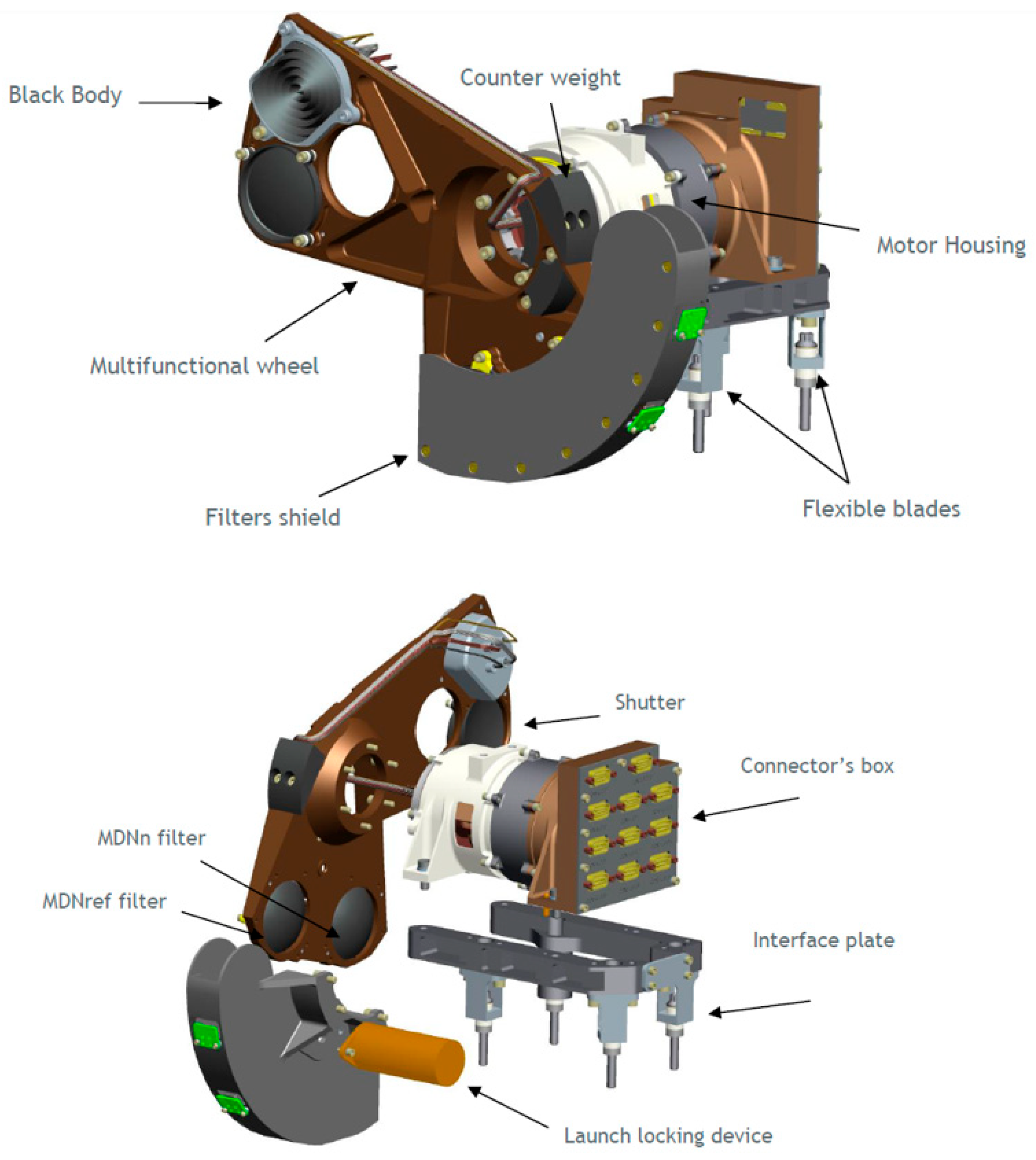
Figure 2.
Scanning mechanism of the MTG-I FCI utilizing the COM during the retrace phase for calibration. IR calibration was initially planned to occur every 10 minutes, aligning with the retrace phase of nominal scan patterns (Courtesy of Thales Alenia Space France).
Figure 2.
Scanning mechanism of the MTG-I FCI utilizing the COM during the retrace phase for calibration. IR calibration was initially planned to occur every 10 minutes, aligning with the retrace phase of nominal scan patterns (Courtesy of Thales Alenia Space France).
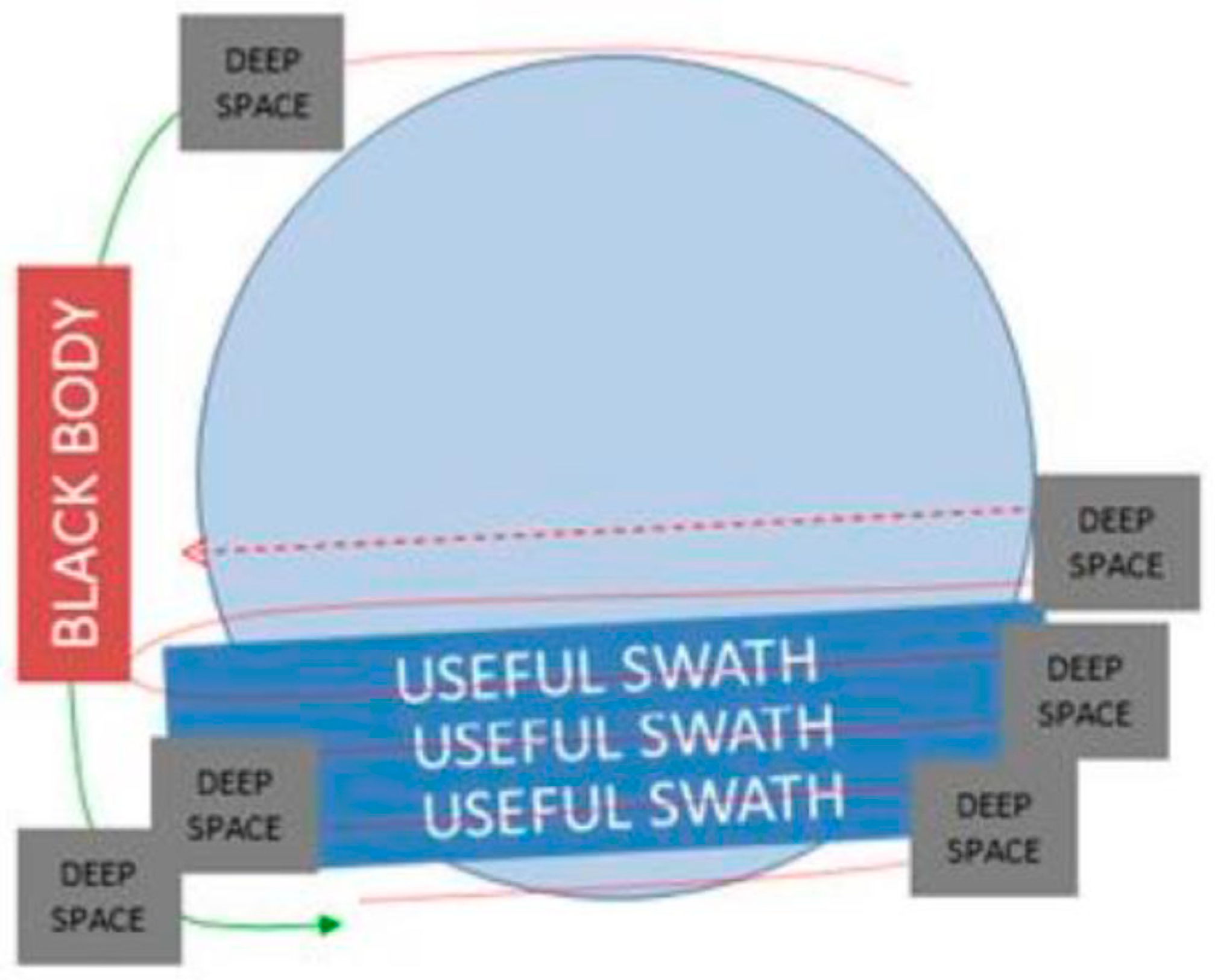
Figure 3.
Flowchart depicting the steps for live processing without blackbody calibration for MTG-I1 FCI.
Figure 3.
Flowchart depicting the steps for live processing without blackbody calibration for MTG-I1 FCI.
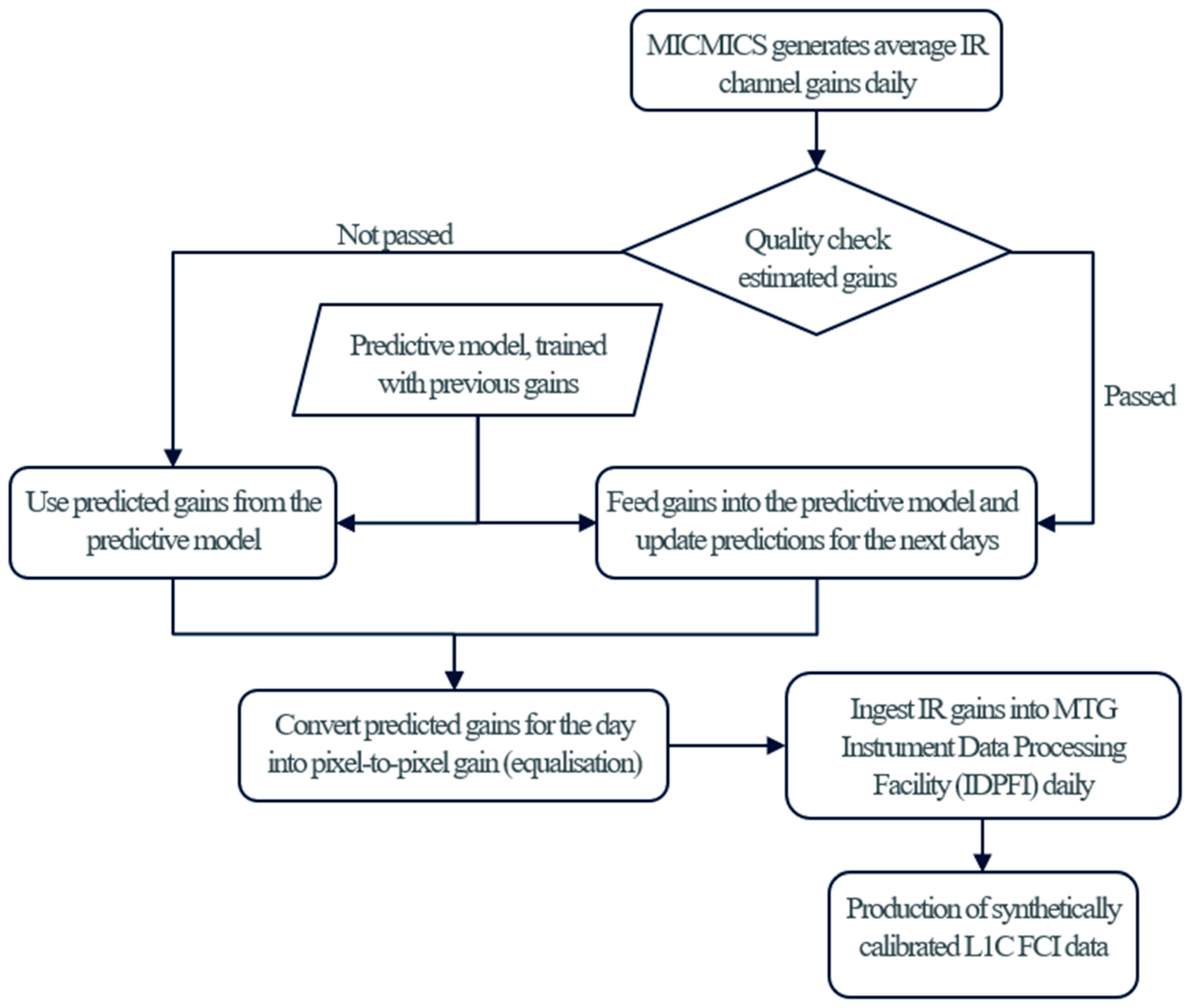
Figure 4.
Example of nighttime collocations for one night. Blue indicates all available collocations, while orange shows selected collocations filtered by space, time, and angle. Left: MetOp-B IASI; Middle: MetOp-C IASI; Right: Combined MetOp-B & C IASI.
Figure 4.
Example of nighttime collocations for one night. Blue indicates all available collocations, while orange shows selected collocations filtered by space, time, and angle. Left: MetOp-B IASI; Middle: MetOp-C IASI; Right: Combined MetOp-B & C IASI.
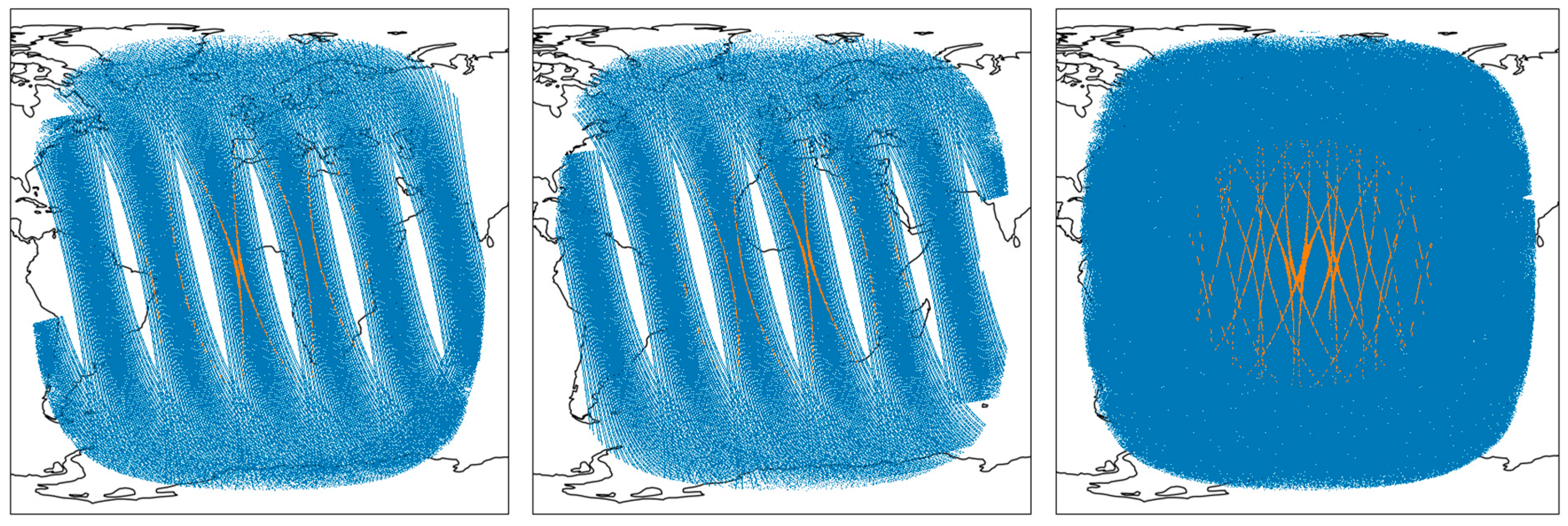
Figure 5.
Comparison between Gain Non-Uniformity (GNU) derived from blackbody acquisitions and GNU extracted using statistical Level-1b equalization (top), the absolute difference between the two GNUs (bottom).
Figure 5.
Comparison between Gain Non-Uniformity (GNU) derived from blackbody acquisitions and GNU extracted using statistical Level-1b equalization (top), the absolute difference between the two GNUs (bottom).

Figure 6.
Density plots of FCI-IASI radiance [mW⋅m⁻²⋅sr⁻¹⋅(cm⁻¹)⁻¹] (top) and brightness temperature [K] (bottom) for 24-hour collocations used in daily gain retrieval during a period when the on-board calibration was not operational. Each plot displays the total number of collocations in the top-left corner and the slope of the weighted linear regression in the bottom-left corner.
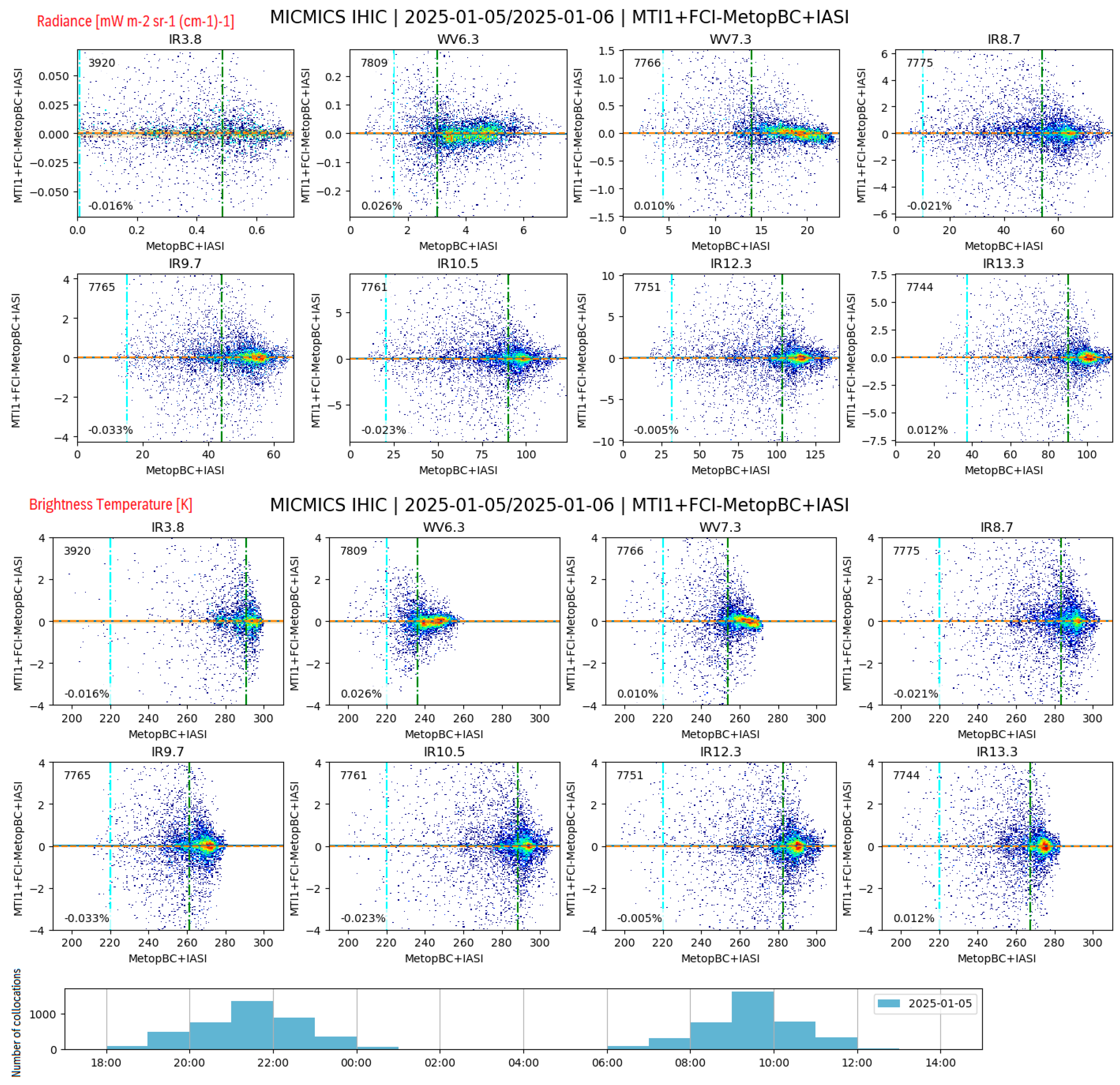
Figure 7.
Density plots of FCI-IASI (top) and FCI-CrIS (bottom) brightness temperatures are shown for the period during which FCI was calibrated against IASI. Red lines represent the user requirements (<0.7 K) for FCI IR channels. Each plot displays the total number of collocations in the top-left corner, the slope of the weighted linear regression in the bottom-left, and the mean bias at the standard scene temperature in the bottom-right.
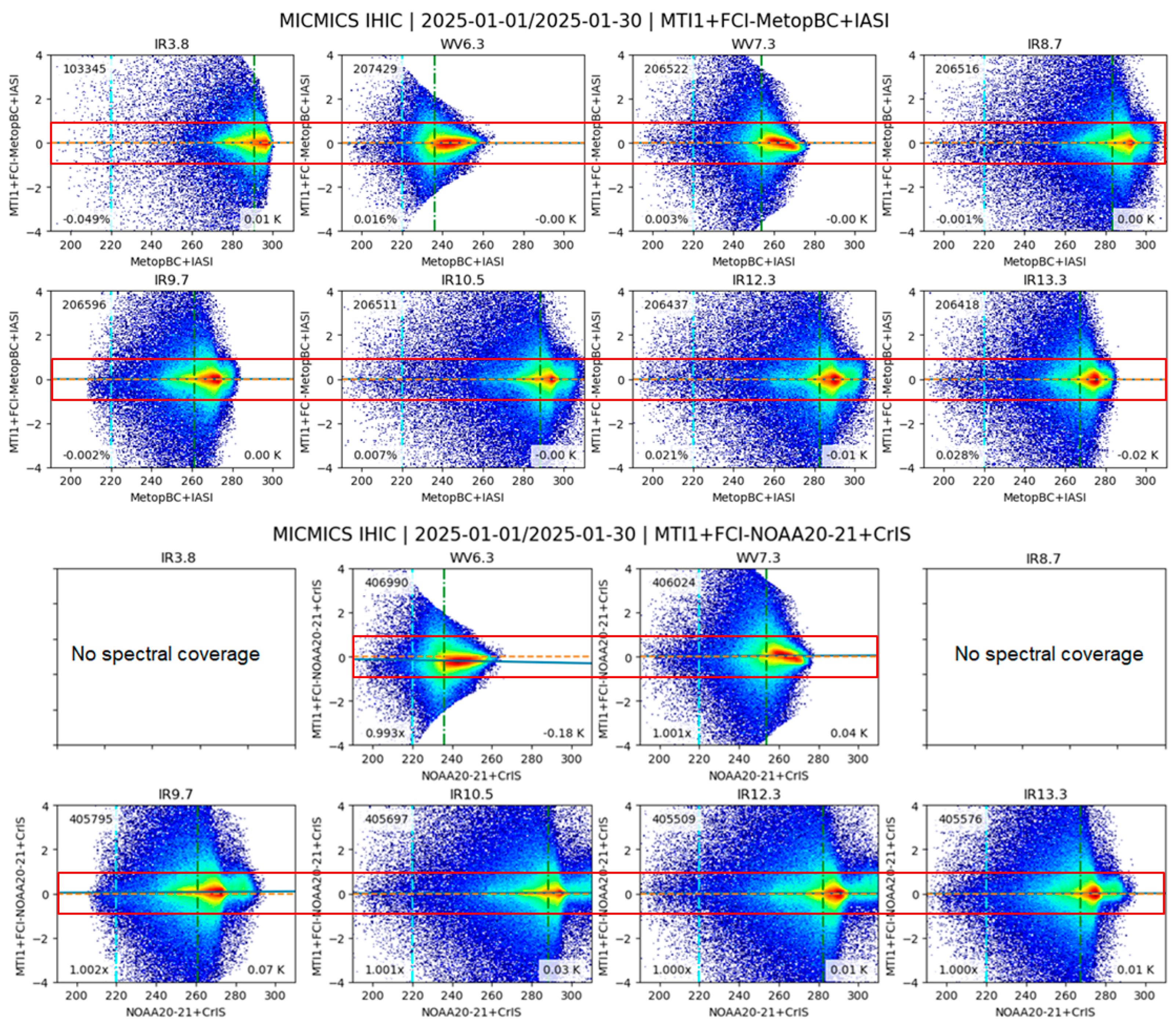
Figure 8.
Evolution of the IR12.3 and WV6.3 radiometric gain as retrieved by MICMICS. The linear evolution of gains is in line with the water-ice contamination of such channel. IR12.3 is significantly more sensitive to ice layer thickness compared to WV6.3, exhibiting a more pronounced gain evolution over time.
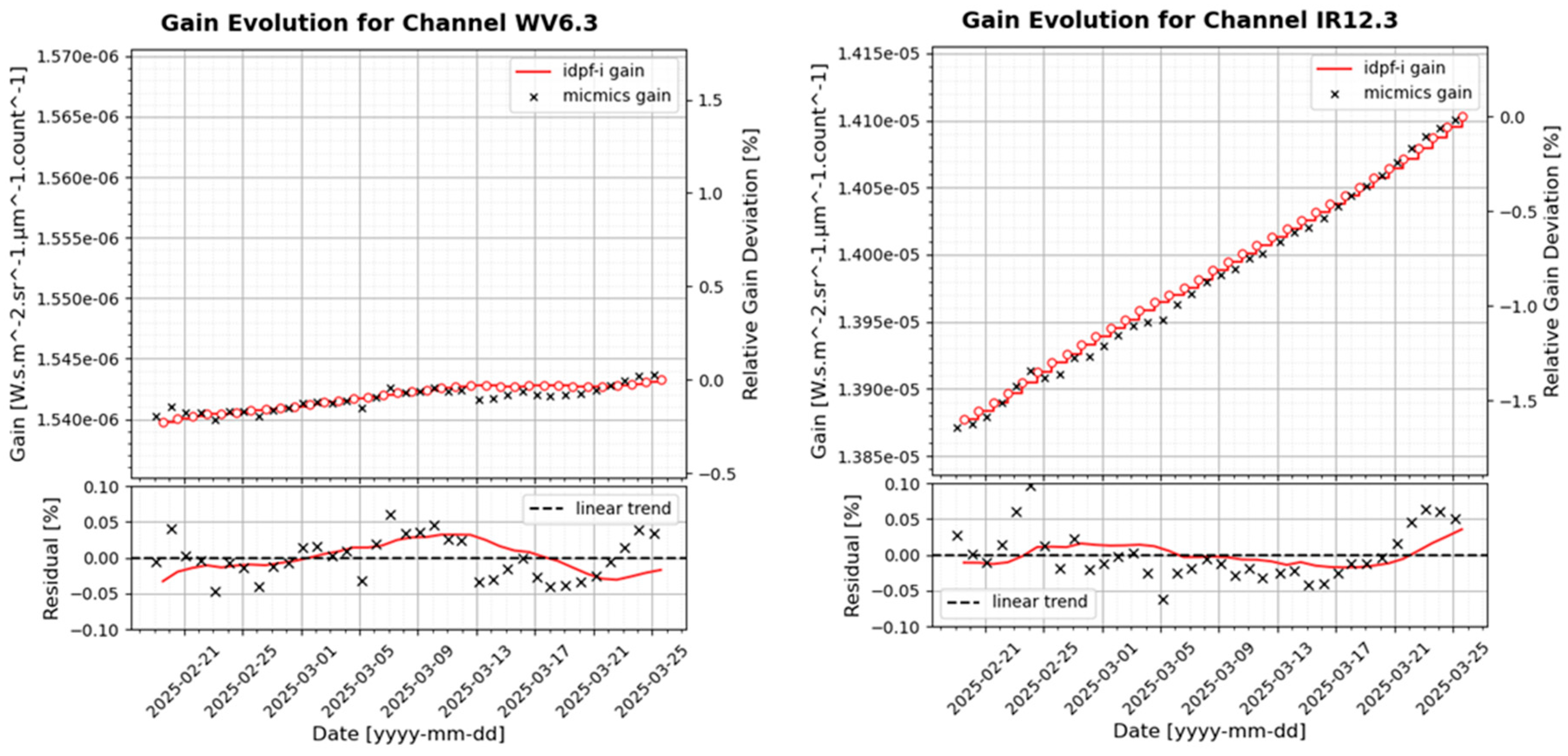
Figure 9.
Comparison of on-board and external gain calibration using MICMICS. Black dots represent on-board calibration gains derived from the blackbody; the green line indicates the best on-board calibration value used by the ground processing facility, while the orange line represents external gains retrieved with MICMICS.
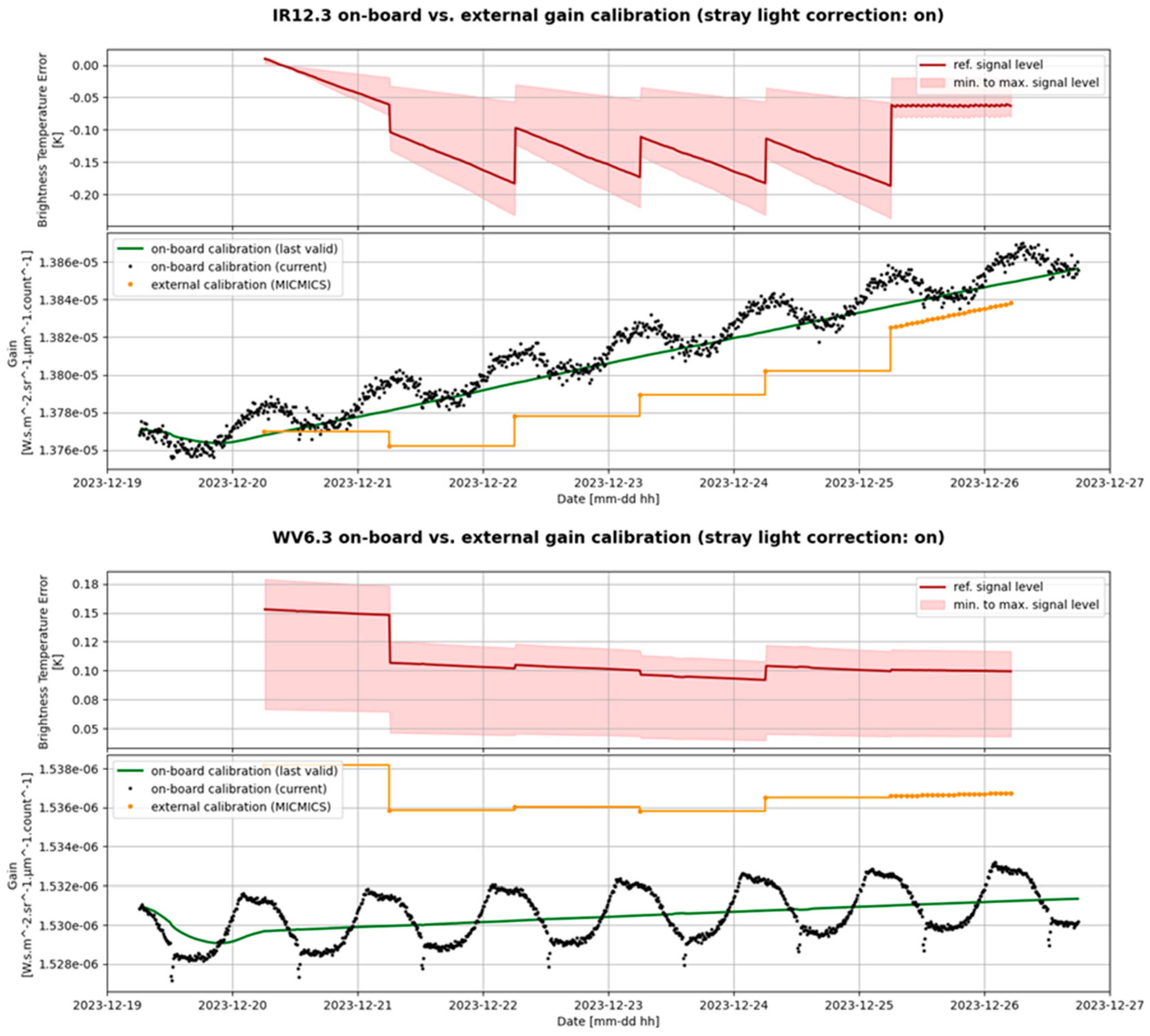
Figure 10.
Radiometric performance of VNIR channels (excluding NIR1.3) over Libya-4 desert, based on 7-day averages. The red lines indicate the User Requirements (<5%) for FCI VNIR channels. VIS04–VIS09 meet the user requirement, while NIR1.6 shows seasonal trend.
Figure 10.
Radiometric performance of VNIR channels (excluding NIR1.3) over Libya-4 desert, based on 7-day averages. The red lines indicate the User Requirements (<5%) for FCI VNIR channels. VIS04–VIS09 meet the user requirement, while NIR1.6 shows seasonal trend.
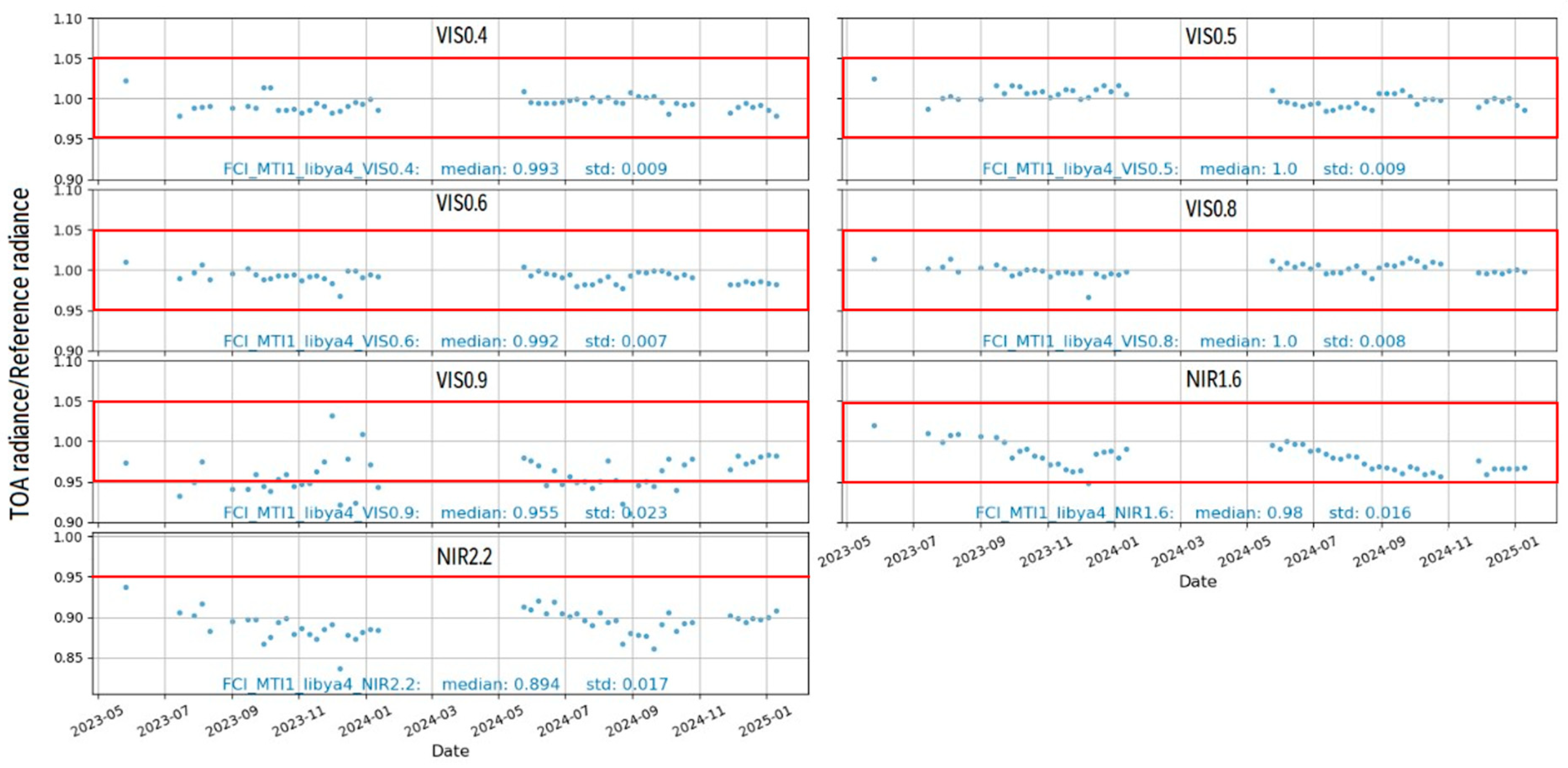

Table 1.
Gain error expressed as brightness temperature error for the FCI infrared channels.
| Channel |
Reference Signal Level [K] |
Brightness Temperature Error [K] |
| IR3.8 | 300 | < 0.05 |
| WV6.3 | 250 | < 0.15 |
| WV7.3 | 250 | < 0.05 |
| IR8.7 | 300 | < 0.20 |
| IR9.7 | 250 | < 0.15 |
| IR10.5 | 300 | < 0.30 |
| IR12.3 | 300 | < 0.20 |
| IR13.3 | 270 | < 0.70 |
Disclaimer/Publisher’s Note: The statements, opinions and data contained in all publications are solely those of the individual author(s) and contributor(s) and not of MDPI and/or the editor(s). MDPI and/or the editor(s) disclaim responsibility for any injury to people or property resulting from any ideas, methods, instructions or products referred to in the content. |
© 2025 by the authors. Licensee MDPI, Basel, Switzerland. This article is an open access article distributed under the terms and conditions of the Creative Commons Attribution (CC BY) license (http://creativecommons.org/licenses/by/4.0/).
Copyright: This open access article is published under a Creative Commons CC BY 4.0 license, which permit the free download, distribution, and reuse, provided that the author and preprint are cited in any reuse.


