
Submitted:
26 May 2025
Posted:
26 May 2025
You are already at the latest version
Abstract
Erosion caused by water droplet impact in high peripheral velocity rotating machinery is an area that is widely researched today. Newer and newer blade protection solutions are being developed for wind power plants, gas turbines, and jet engines to reduce erosion and maintain efficient power generation. However, this phenomenon on turbochargers used in the automotive industry has been the subject of a limited number of studies, despite advanced technologies such as alternative fuels and exhaust gas recirculation increasing the water droplet formation and thus increasing the erosion rate of the impeller. This study investigated the resistance to erosion of three different compressor wheel coatings. Tests were carried out according to the ASTM-G73-10 standard using a custom-developed test apparatus. The degree of erosion was measured by continuous precision mass measurement. Electron microscopy was used to detect structural changes on the surface, both on the base material and on the coating. Significant differences in the extent of erosion were observed for the different coatings. As a result, the isentropic efficiency of the compressor decreased in all cases but varied depending on the type of coating.
Keywords:
water droplet erosion
; coating
; compressor blade
; isentropic efficiency
1. Introduction
The erosion of high-speed rotating impellers by water droplets and the creation of solutions to avoid this is a challenge that is addressed in many engineering fields today. Physicality of this phenomenon were described by Worthington [1] as early as the 1870s, but the real impetus for its research came with the widespread introduction of steam power plants in the 1950s. To increase the efficiency of energy production, increasingly large turbine structures were built, and the steam was expanded through so many stages that it appeared as condensed liquid on the blades of the last stages and caused significant erosion on them due to the high-speed impact [2]. In this field of research, the most common solutions for erosion resistance are the use of different steel and titanium alloys (e.g. Ti6Al4V, X12CrNiMoV12-3) as well as different post-mould coatings such as WC-12Co, WC-17Co with high velocity oxygen fuel (HVOF) process [3,4,5,6,7]. Wind power plants are increasingly using larger and higher-speed structures to increase the efficiency of power generation. Consequently, minimizing the weight of the rotating blades is critical and soft metals, and even more so polymer materials, are most used. However, these materials can also suffer significant erosion when they collide with rainwater or sand, reducing the efficiency of power generation by up to 20-25% [8,9]. To ensure resistance, a post-mould protective layer is most used, the main advantages of which are that the base material does not need to be modified and can be removed and easily replaced during maintenance. In his review article, Herring et al. [10] describes several techniques, coating materials and coating technologies, listing their advantages and disadvantages. Engel [11] mentions as a new area, the erosion of aircraft by rainwater on their various components, caused mainly by high-speed impact. Also, in the field of aeronautics, Tobin’s et al. [12] aspect of research was the study of water erosion of the aircraft nose covering plate (radome), since an important characteristic of the materials used is the ease with which radio signals can be transmitted and received through it, but this property has a negative effect on resistance to erosion. To reduce the extent of erosion of aircraft engine power, research of Bonu et al. [13] compared several material grades mentioning several advantages and drawbacks.
Other application-independent material structure research on solid-state erosion has also achieved several results in reducing the rate of erosion. In his research, Debasish et al. [14] showed that torch input power is the most significant affecting factor to be controlled from the viewpoint of erosive wear, with an increase in the power, the erosion rate is significantly reduced when applying Mo-TiN coatings on turbocharger compressor wheel’s Al-Si substrates with ASP.
In the field of automotive engineering, the so-called low-pressure exhaust gas recirculation (LP-EGR) is an increasingly widespread technology that can significantly reduce NOx emissions of internal combustion engines and, in the case of gasolene engines, reduce the specific fuel consumption at certain operating points [15,16,17,18]. However, a major drawback of this technology is that the water vapor content of the exhaust gas condenses into liquid and creates a high velocity collision with the turbocharger's compressor blades, which can cause significant erosion on it. Compressor impellers are typically made of aluminum alloy, as it is important to keep the rotor structure inertia as low as possible. These alloys, however, do not provide sufficient resistance to erosion caused by water droplet impact, so detailed research in this area is important. However, only a small number of publications have been published to date. Karstadt et al. [19] conducted water erosion experiments with different parameters on compressor wheels of the same material and report that the application of a coating of a certain material, which they did not specify, was able to significantly reduce the erosion rate under the same testing duration and conditions.
Another important aspect is the future use of alternative fuels, as their combustion typically results in a higher specific water vapor content, which can lead to greater condensation and therefore greater erosion for the same energy release [20,21].
The number of erosion experiments carried out on turbochargers’ compressor wheels in literature is very small. Although these experiments have produced very important findings, they have not provided a sufficiently detailed description of how they were carried out to ensure comparability. Furthermore, important parameters such as the chemical composition of the base material and/or coating and their hardness values have not been described, even though they have a significant influence on the degree of erosion that occurs.
In the present study, detailed erosion tests are presented for 3 compressor wheels commercially available, with same geometry and base material, but with different types of coating tested on a specific test equipment conforming to ASTM-G73-10 [22]. No further information on these test specimens (hereafter referred to as Sample 1,2,3) was available prior to the tests, so the investigation of the chemical compositions and the determination of the hardness values for both the base material and the coating is an essential element of the research. The provision of these data is key to accurately describing erosion tests, which has not been addressed or only tangentially addressed in previous research on turbochargers. The process of erosion was described by precision mass measurement and microscopic imaging with standard hardness measurement and chemical composition determination. At the end of the tests, the change in isentropic efficiency of the damaged compressor impellers were detected by mapping process.
2. Materials and Methods
To ensure reproducibility and comparability, the tests of the present study have been prepared in accordance with the requirements of ASTM-G73-10. This standard specifies that surfaces subjected to water erosion must be subjected to a hardness measurement process prior to testing and then the tests must be carried out under precisely controlled parameter settings.
2.1. Test Apparatus
For the possibility of precise control of the test parameters over a wide range, a specific test apparatus has been built, comprising the main units shown in the schematic diagram below (Figure 1).
According to the ASTM-G73-10 standard, the velocity range of water droplets impacting solids should be between 60 m/s and 600 m/s. In the present tests, an impact velocity of 250 m/s was used, which corresponds to a common medium load level for turbochargers of this size. The analysis of the effect of further speed ranges on erosion is the subject of a forthcoming publication. The primary objective in the present case being to compare the resistance to erosion of coatings of different materials under the same conditions. The target speed was set as a vectorial sum of the rotating rotor circumferential speed and the water droplet speed considering 90° impact angle and calculated based on Hattori’s et al. equation [23].
The circumferential speed of the impacted point on the blades () was achieved by compressed air propulsion using a velocity sensor and a PID controller, while the speed of the water droplets () was implemented by a pressurized hydrophore tank, which, unlike other publications, eliminates the pressure pulsation of commonly used pumps and provides a constant pressure level. During the tests, the maximum deviation of the impact speed from the target value was +- 0.3%. It was also critical to form water particles of the same size and to detect their collision frequency. For this purpose, a so-called Water Droplet Generator (WDG) unit was used, which uses a piezo-electric excitation to break the constant pressure water jet coming from the hydrophore tank into water droplets of uniform size and frequency, based on the Rayleigh-Plateau instability principle [24]. In the present investigations, a 375 μm pinhole with a water pressure of 4 bar (rel) and a frequency of 10,000 Hz was used to form droplets of 845 in diameter. Uniform droplet size and uniform droplet formation were verified by using a high-speed camera (HSC), as illustrated on Figure 2.
2.2. Erosion Detection
After the installation and commissioning process, the investigation has started. The erosion tests were interrupted at certain intervals for each coating type to record the amount of erosion produced using a Sartorius ultra-precision (0.001 g) mass measuring device. Tests were run for the same length of time for all three samples. Sample 1 and 2 suffered significant damage after 9,72x10^8 number of impacted water droplets. In order to analyze the change in isentropic efficiency between the original and the damaged samples equipped turbocharger, the tests were inserted at this point, as further damage would have introduced a risk of high level of imbalance, and hence destruction [25], to the samples that would have compromised the generation of the mentioned isentropic efficiency curves.
For observing water droplet erosion damage mechanisms in detail, samples were examined with a Zeiss Crossbeam 350 scanning electron microscope (SEM). The measurements were done at a resolution of 3072x2304 and with an accelerating voltage of 6.0kV, to get a qualitative image of the eroded specimen.
3. Results and Discussion
3.1. Mass Loss and Hardness
As mentioned in the previous chapter, the extent of erosion was detected visually and by mass measurement at given intervals. The extent of damage at the end of the tests (9.72x10^8 impacted droplets) for each sample is illustrated in Figure 3.
As shown in Figure 3, Sample 1 (a,) and Sample 2 (b,) suffered similar levels and patterns of erosion. Another interesting observation for both samples is the complete coating delamination and base material wear on the back of the blades (c,). In contrast, Sample 3 showed significantly less erosion (d,) and no coating delamination on its back (e,).
The result of the mass loss measurements is shown in Figure 4, where the x-axis shows the number of water droplets impacted, and the y-axis shows the mass loss compared to the original mass of the compressor wheel in percentage.
To ensure that the chemical composition of the base material and the coatings accurately characterize the specimens tested, these structural properties were subsequently checked by destructive testing. In all three cases, the hardness of the base material was determined by averaging 5-5 impression samples on a Vickers KB 30 hardness tester at 10 kp load according to ISO 6507-1:2024. The hardness of the coatings was determined on a grinded cross section as shown in Figure 5, using a Buehler Micromet microhardness tester with a Vickers method at 0.05 kp load.
Table 1 summarizes the hardness values of the different samples of base material and coating.
It can be observed that the hardness values of the base material of the tested samples are almost identical. However, the hardness value of the coating of Sample 3 is significantly higher than the first two (18%).
3.2. Chemical Composition
The reason for hardness difference was revealed by the determination of the chemical composition of the samples using a WAS Foundry Master optical emission spectrometer. Based on the results, the base material of the samples was all classified as EN AW-2618A (according to EN 573-3:2019), however, data in Table 2. shows that there is a difference in the chemical composition of the coatings.
For Sample 1 and 2, the same constituent elements were detected, and the slight difference in their weight percentages represented only a 5 HV difference in hardness value. However, for Sample 3, Si was also detected with 3.64 wt%, which is known to be a high hardness element. Its presence represents a hardness value increase of almost 18% compared to the other two samples. It is known from several studies on water erosion of solids that increasing the hardness value of a solid increases its resistance to erosion [26,27,28,29]. The mass loss curves in Figure 4 show a good correlation with this determination, but other effects can also be observed. Up to a number of impacted water droplets of about 2.5x10^8, Sample 1 suffered the most wear. Sample 2 showed slightly lower loss of material, presumably due to the higher nickel and phosphorus content of the coating, which therefore has a higher ductility value. As the research of Ahmad et al. [30] shows, besides the hardness value, the ductility value also has a significant influence on the amount of erosion that occurs, as it increases the elasticity of the material, thus increasing its ability to absorb impact elastically. In the case of Sample 3, the higher coating hardness is dominating, so the wear rate is significantly lower than at Sample 1 and 2.
3.3. Wear Analysis with SEM
The observation of the damage mechanisms in detail were examined by SEM with settings mentioned in the chapter before. The time points of the measurements were defined so that the early stages of erosion can be captured. Note that both compressor impellers coating have Ni-P-C content, however, Sample 3 features SiC particles incorporated in the coating to enhance its’ hardness.
The SEM images depicted in Figure 6 (a, b) show the observations made of the eroded surface in the case of Sample 1 (Sample 2 showed very similar wear pattern) after a number of impacted water droplets of about 2.5x10^8. Figure 6 (a) displays the wear caused by the impinging droplets on the leading edge and it can be clearly seen that damage has already started to initiate on the coating, though the substrate is not yet revealed. In Figure 6 (b), small pits caused by cavitation erosion can be seen at the inner side of the leading edge. This phenomenon can be explained by the fact that upon impact with the rotating blades, water droplets suffer significant local pressure oscillations leading to the formation of gas bubbles inside the fluid, due to its’ static pressure dropping below its’ vapor pressure. As the fluid travels after the collision downstream into higher pressure regions, these cavitation bubbles collapse, leading to pressure waves exerted to the surface with high amplitudes. This finding is in line with the study by Mann [31], who showed a similar phenomenon in the initial stage of his water erosion test of laser-treated stainless steel.
Figure 7 (a) depicts the state of the specimen after around 9,72x10^8 impacted droplets. The findings show that erosive wear has already reached a point where a substantial amount of material has been removed from the blades. It is worth mentioning that part of the coating has detached from the substrate near the WDE zone, directly exposing it to the impinging water droplets, possibly leading to an acceleration in the rate of erosion. The removal of the coating can be explained with the poor adhesive bonding with the substrate. Upon repeated impacts, the coating slowly peeled off the surface, with the droplets finding their way between the two materials. As the peeling spreads, small cracks are initiated in the coating at stress concentration zones (as can be seen in Figure 7 (b)), which weakened the integrity of the material, leading to the removal of larger fragments over time.
Figure 8 (a,b) illustrates the condition of Sample 3 after a number of impacted water droplets of about 2.5x10^8. In comparison to Sample 1 and 2, the observed damage seems lower, however, increased surface roughness can be identified along the leading edge within the impact zone. It is important to note that no clear evidence of erosive wear initiation was detected during the examinations.
Figure 9 (a, b) illustrates that after around 9,72x10^8 impacted droplets, material removal on Sample 3 has initiated at the leading edge of the compressor blade, however, the extent of erosion is notably less severe compared to Sample 1 and 2. It is also noteworthy that no cavitation erosion pits were observed on the surface in this case, which may be attributed to the more favorable hardness properties of the material, potentially enhancing its resistance to cavitation-induced damage.
It is also worth noting that at Sample 3 the coating remains fully adhered to the substrate surface. The reason for this phenomenon is presumably the presence of SiC, which increases the adhesion strength between the surfaces, and it hardens the matrix and prevents crack propagation toward the interface. However, it is important to mention that the authors have no information on the preparation of the substrate before the coating process. Based on the microscope images, the same preparation process and quality can be assumed, but further investigations are suggested to analyze the effects of the surface preparation of base material.
3.4. Compressor Isentropic Efficiency Analysis
To analyze the effect of the erosion on the turbocharger operation, compressor characteristic curves were determined using a turbocharger testbench available at Széchenyi István University. Sample 1 and 2 suffered much higher erosion than Sample 3. In each case, the compressor characteristic curves were considered at 3 speed lines in the middle of the impeller operation regime to comprehensively analyze the area for the isentropic efficiency of the compressor. In each case, the comparison was made between the isentropic efficiency values in an original state and the eroded state of the turbocharger compressor impeller. Figure 10 illustrates the analysis performed. For Sample 3, the isentropic efficiency reduction was negligibly low, within measurement uncertainties. For Samples 1 and 2, the reduction in isentropic efficiency was ~2.5%, which is significant. The reduction of isentropic efficiency will result in higher fuel consumption and thus higher CO2 emissions. The results of Samples 1 and 2 were indistinguishably similar, so for better visibility only the results of Sample 1 are shown in Figure 10.
In addition to the significant reduction in isentropic efficiency, there was also a shift in the surge (left end of the curves) and choke (right end of the curves) limits on each line, which also negatively affects the fuel consumption of the engine
4. Conclusions
This study investigated 3 turbocharger compressor impeller coatings during impact with high velocity water droplets. The 3 impellers had identical geometry and were applied on the same turbocharger, but each of them had coatings with different chemical compositions. The main objective of this study was to describe the investigation accurately and in detail, and to align it with the ASTM-G73-10 standard for reproducibility and comparability in future tests. The test samples were from the same type of turbocharger, but only few information was available prior to testing.
The first two samples (Samples 1, 2) showed almost identical erosion rates, which can be attributed to the nearly identical coating and base material hardness values. For these two samples, the chemical composition of the coatings was also almost identical, but for Sample 2, the higher Ni content resulted in a negligible but improved erosion resistance. However, Sample 3 showed significantly less erosion over the same test interval. The chemical composition tests carried out here found that the coating also contained 3.64 wt% SiC, resulting in a hardness value 18% higher than the first two samples. The studies also showed that, presumably due to the better adhesion properties of SiC, no delamination of the coating from the substrate occurred in Sample 3, while significant delamination was observed in Samples 1 and 2. This was confirmed by SEM images.
A comparative analysis of the isentropic efficiency of the compressor was performed with the more damaged samples. The measurement on 3 speed line showed an efficiency degradation of 2.5 %, which can be considered as significant.
Overall, the study reinforces the importance of coating hardness, adhesion, and microstructure in mitigating water droplet erosion in turbocharged systems.
Future work should address the effects of surface preparation before the coating process, and investigation of other chemical compound coatings on erosion resistance. Because the unique test apparatus was created and is available, it allows the future analysis of the impact velocity, the number of water particles impacting during a given interval, and the angle of impact on erosion using various materials with different chemical composition and hardness value.
Author Contributions
Conceptualization, R.T. and I.Z.; methodology, R.T.; software, R.T.; investigation, R.T. and B.D.; material analysis R.T.; microscope analysis, N.K. and M.Z.T.; writing-original draft preparation, T.R. and N.K.; writing-review and editing, C.T.-N.; project administration, R.T. All authors have read and agreed to the published version of the manuscript.
Funding
This article is published in the framework of the project “Production and Validation of Synthetic Fuels in Industry-University Collaboration”, project number “ÉZFF/956/2022-ITM_SZERZ”. „Supported by the EKÖP-24-… UNIVERSITY RESEARCH FELLOWSHIP PROGRAM of the Ministry for Culture and Innovation from the source of the National Research, Development and Innovation Fund.”.
Institutional Review Board Statement
Not applicable.
Informed Consent Statement
Not applicable.
Data Availability Statement
Data are available upon request from the corresponding author.
Conflicts of Interest
The authors declare no conflicts of interest.
Abbreviations
The following abbreviations are used in this manuscript:
| ASP | Atmospheric Plasma Spray |
| HV | Vickers Hardness |
| HVOF | High-velocity Oxygen Fuel |
| HSC | High-speed Camera |
| LP-EGR | Low-pressure Exhaust Gas Recirculation |
| PID | Proportional-Integral-Derivative |
| SEM | Scanning Electron Microscope |
| Circumferential speed of the compressor | |
| Circumferential speed at the impact point | |
| Water droplet speed | |
| Impact speed of water droplet | |
| WDG | Water Droplet Generator |
| wt | Weight ratio |
References
- Worthington, A.M. On the forms assumed by drops of liquids falling vertically on a horizontal plate. Royal Society 1877, 25, 171–178. [Google Scholar]
- Ahmad, M.; Schatz, M.; Casey, M.V. Experimental investigation of droplet size influence on low pressure steam turbine blade erosion. Wear 2013, 303, 83–86. [Google Scholar] [CrossRef]
- Mahdipoor, M.S.; Tarasi, F.; Moreau, C.; Dolatabadi, A.; Medraj, M. HVOF sprayed coatings of nano-agglomerated tungsten powders for water droplet erosion application. Wear 2015, 330, 338–347. [Google Scholar] [CrossRef]
- Gerdes, C.; Karimi, A.; Bieler, H.W. Water droplet erosion and microstructure of laser-nitrided Ti-6Al-4V. Wear 1995, 186, 368–374. [Google Scholar] [CrossRef]
- Di, J.; Wang, S.; Yan, X.; Jiang, X.; Lian, J.; Zhang, Z.; Xie, Y. Experimental research on water droplet erosion resistance characteristics of turbine blade substrate and strengthened layers materials. Materials 2020, 13, 4286. [Google Scholar] [CrossRef]
- Zhang, Z.; Zhang, D.; Xie, Y. Experimental study on water droplet erosion resistance of coatings (Ni60 and WC-17Co) sprayed by APS and HVOF. Wear 2019, 432–433, 202950. [Google Scholar] [CrossRef]
- Shipway, P.H.; Gupta, K. The potential of WC-Co hardmetals and HVOF sprayed coatings to combat water-droplet erosion. Wear 2011, 271, 1418–1425. [Google Scholar] [CrossRef]
- Dashtkar, A.; Hadavinia, H.; Sahinkaya, M.N.; Williams, N.A.; Vahid, S.; Ismail, F.; Turner, M. Rain erosion-resistant coatings for wind turbine blades: A review. Polymers and Polymer Composites 2019, 27, 443–475. [Google Scholar] [CrossRef]
- Slot, H.M.; Gelick, E.R.M.; Rentrop, C.; van der Heide, E. Leading edge erosion of coated wind turbine blades: Review of coating life models. Renewable Energy 2015, 80, 837–848. [Google Scholar] [CrossRef]
- Herring, R.; Dyer, K.; Martin, F.; Ward, C. The increasing importance of leading-edge erosion and a review of existing protection solutions. Renewable and Sustainable Energy Reviews 2019, 115, 109382. [Google Scholar] [CrossRef]
- Engel, O.G. Waterdrop collision with solid surfaces. Journal of Research of the National Bureau of Standards 1955, 54, 281–298. [Google Scholar] [CrossRef]
- Tobin, E.F.; Young, T.M.; Raps, D.; Rohr, O. Comparison of liquid impingement results from whirling arm and water-jet rain erosion test facilities. Wear 2011, 271, 2625–2631. [Google Scholar] [CrossRef]
- Bonu, V.; Barshilia, H.C. High-temperature solid particle erosion of aerospace components: Its mitigation using advanced nanostructured coating technologies. Coatings 2022, 12, 1979. [Google Scholar] [CrossRef]
- Debasish, D.; Panigrahi, A.; Sengupta, P.; Bajpai, S. Erosive wear characteristic of Mo-TiN composite coatings on turbocharger compressor wheel using Taguchi experimental design. Materials Today: Proceedings 2022, 66, 534–539. [Google Scholar] [CrossRef]
- Lapuerta, M.; Ramos, Á.; Fernández-Rodríguez, D.; González-Garcia, I. High-pressure versus low-pressure exhaust gas recirculation in a Euro 6 diesel engine with lean-NOx trap: Effectiveness to reduce NOx emissions. International Journal of Engine Research 2018, 20, 155–163. [Google Scholar] [CrossRef]
- Serrano, J.P.; Piqueras, P.; Navarro, R.; Tarí, D.; Meano, C.M. Development and verification of an in-flow water condensation model for 3D-CFD simulations of humid air streams mixing. Computers and Fluids 2018, 167, 158–165. [Google Scholar] [CrossRef]
- Desantes, J.M.; Luján, J.M.; Pla, B.; Soler, J.A. On the combination of high-pressure and low-pressure exhaust gas recirculation loops for improved fuel economy and reduced emissions in high-speed direct-injection engines. International Journal of Engine Research 2013, 14, 3–11. [Google Scholar] [CrossRef]
- Siokos, K.; Koli, R.; Prucka, R.; Schwanke, J.; Miersch, J. Assessment of cooled low pressure EGR in a turbocharged direct injection gasoline engine. SAE International Journal of Engines 2015, 8, 1535–1543. [Google Scholar] [CrossRef]
- Karstadt, S.; Werner, J.; Münz, S.; Aymanns, R. Effect of water droplets caused by low pressure EGR on spinning compressor wheels. In Proceedings of the 19th Supercharging Conference, Dresden, Germany, 17–18 September 2014. [Google Scholar]
- Venu, H.; Subramani, L.; Raju, V.D. Emission reduction in a DI diesel engine using exhaust gas recirculation (EGR) of palm biodiesel blended with TiO2 nano additives. Renewable Energy 2019, 140, 245–263. [Google Scholar] [CrossRef]
- Moroz, S.; Bourgoin, G.; Luján, J.M.; Pla, B. Acidic condensation in low pressure EGR systems using diesel and biodiesel fuels. SAE International Journal of Fuels and Lubricants 2009, 2, 305–312. [Google Scholar] [CrossRef]
- ASTM International. ASTM G73-10: Standard Practice for Liquid Impingement Erosion Testing; ASTM International: West Conshohocken, PA, 2010. [Google Scholar]
- Hattori, S.; Kakuichi, M. Effect of impact angle on liquid droplet impingement erosion. Wear 2013, 298–299, 1–7. [Google Scholar] [CrossRef]
- Rayleigh, L. On the instability of jets. Proceedings of the London Mathematical Society 1878, 10, 4–13. [Google Scholar] [CrossRef]
- Rácz, B.; Pesthy, M.; Sass, P.; Rohde-Brandenburger, J. Experimental investigation of vibroacoustic behavior of an automotive turbocharger with semi-floating bearing. Vehicle and Automotive Engineering 2020, 245–255. [Google Scholar] [CrossRef]
- Kirols, H.S.; Kevorkov, D.; Uihlein, A.; Medraj, M. The effect of initial surface roughness on water droplet erosion behaviour. Wear 2015, 342–343, 198–209. [Google Scholar] [CrossRef]
- Luiset, B.; Sanchette, F.; Billard, A.; Schuster, D. Mechanisms of stainless steels erosion by water droplets. Wear 2013, 303, 459–464. [Google Scholar] [CrossRef]
- Shaik, R.A.; Ibrahim, M.E.; Gujba, A.K.; Pugh, M.D.; Medraj, M. On the role of strain hardening and mechanical properties in water droplet erosion of metals. Tribology International 2022, 173, 107649. [Google Scholar] [CrossRef]
- Ibrahim, M.E.; Marzbali, M.; Gujba, A.K.; Medraj, M. The role of hardening and roughening during the incubation period in water droplet impingement erosion of Ti-6Al-4V. Wear 2023, 520–521, 204658. [Google Scholar] [CrossRef]
- Ahmad, M.; Casey, M.; Sürken, N. Experimental assessment of droplet impact erosion resistance of steam turbine blade materials. Wear 2009, 267, 1605–1618. [Google Scholar] [CrossRef]
- Mann, B.S. Water droplet and cavitation erosion behavior of laser-treated stainless steel and titanium alloy: Their similarities. Journal of Materials Engineering and Performance 2013, 22, 3647–3656. [Google Scholar] [CrossRef]
Figure 1.
Schematic drawing of the Erosion Testbench.
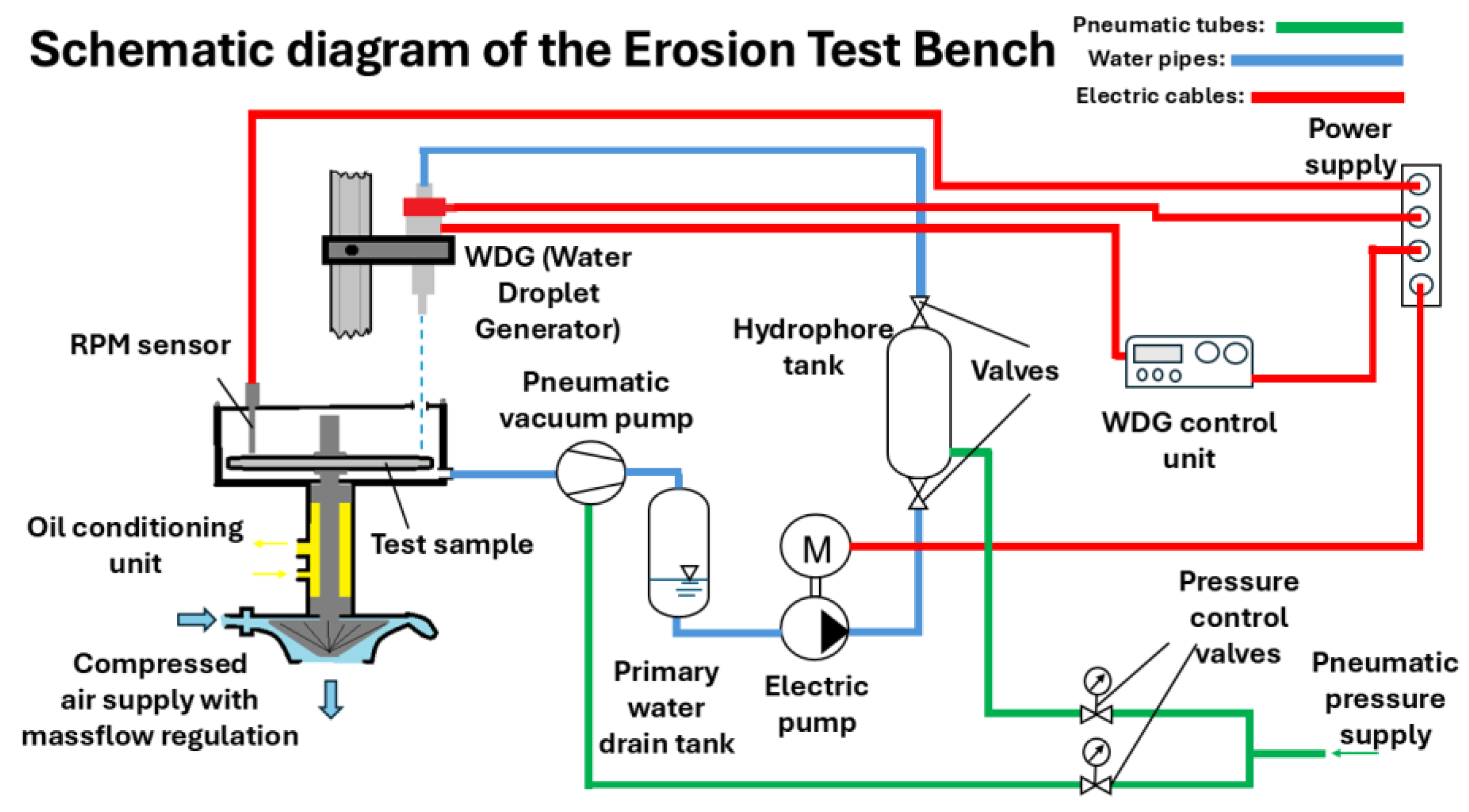
Figure 2.
High-speed camera image of the generated water droplets at the commissioning phase.
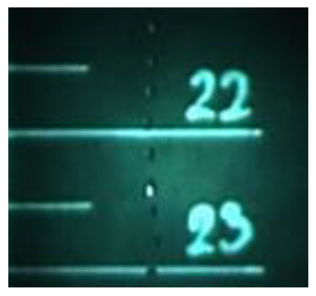
Figure 3.
Erosion detection at the end of the tests: (a), Sample 1; (b), Sample 2; (c), backplate of Sample 1 which is similar to Sample 2; (d), Sample 3; (e), backplate of Sample 3.
Figure 3.
Erosion detection at the end of the tests: (a), Sample 1; (b), Sample 2; (c), backplate of Sample 1 which is similar to Sample 2; (d), Sample 3; (e), backplate of Sample 3.
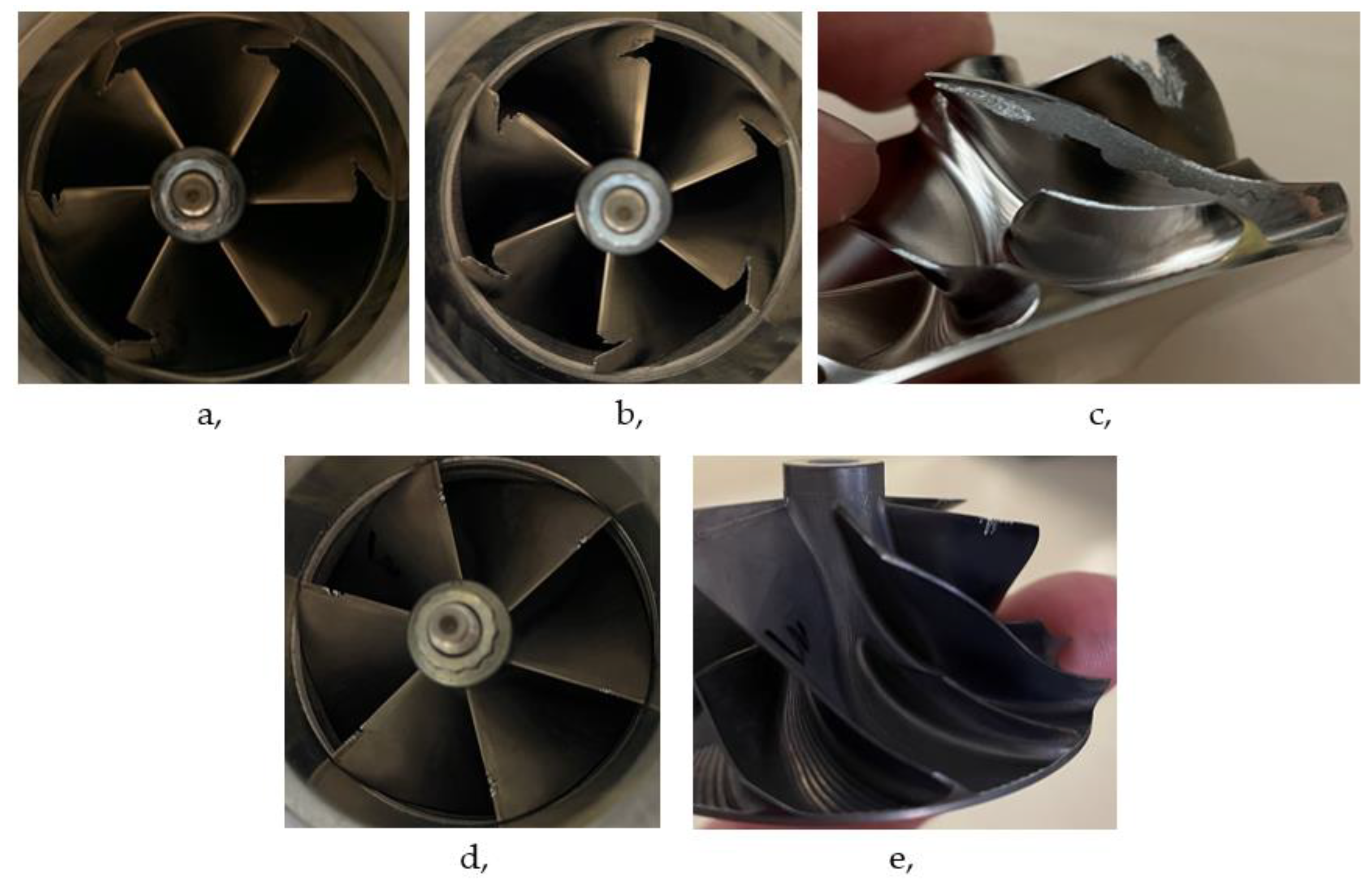
Figure 4.
Mass loss characteristics of Coating 1,2 and 3 due to droplet erosion.
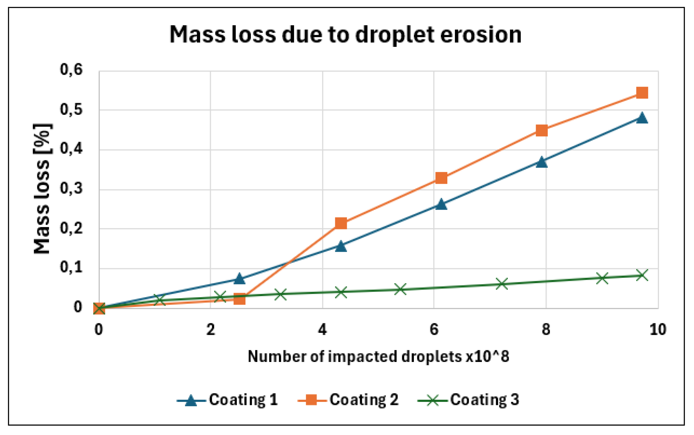
Figure 5.
Microhardness measurement on the coating.
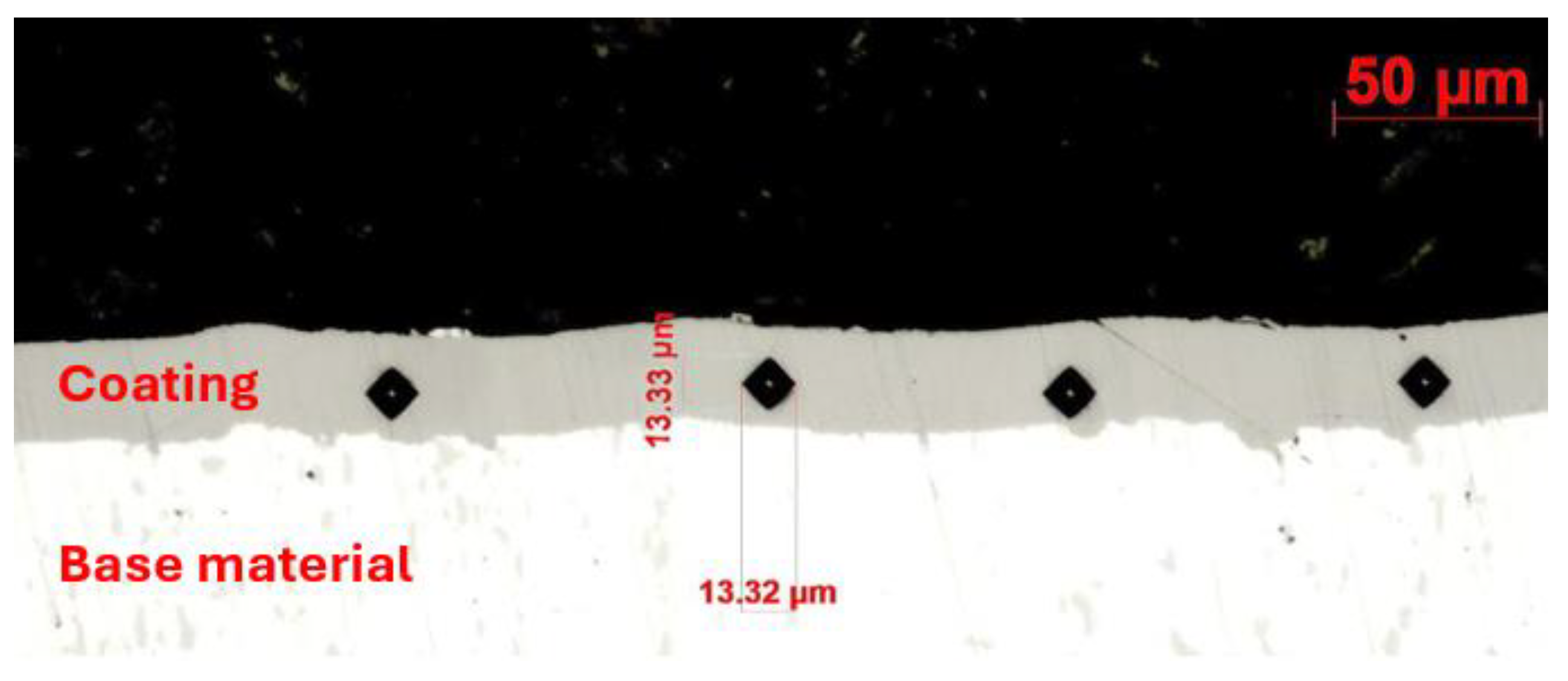
Figure 6.
SEM image of Sample 1 after 2,5x10^8 collided water droplet: (a), water droplet erosion (WDE) (resolution: x1000); (b), Cavitation erosion pits (resolution: x1890).
Figure 6.
SEM image of Sample 1 after 2,5x10^8 collided water droplet: (a), water droplet erosion (WDE) (resolution: x1000); (b), Cavitation erosion pits (resolution: x1890).
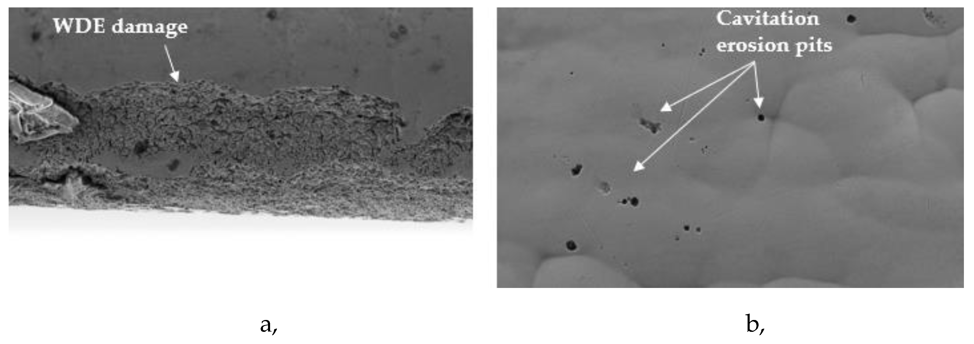
Figure 7.
SEM image of Sample 1 after 9,72x10^8 collided water droplet: (a), coating detachment (resolution: x81); (b), micro-cracks propagation on the coating (resolution: x1000).
Figure 7.
SEM image of Sample 1 after 9,72x10^8 collided water droplet: (a), coating detachment (resolution: x81); (b), micro-cracks propagation on the coating (resolution: x1000).
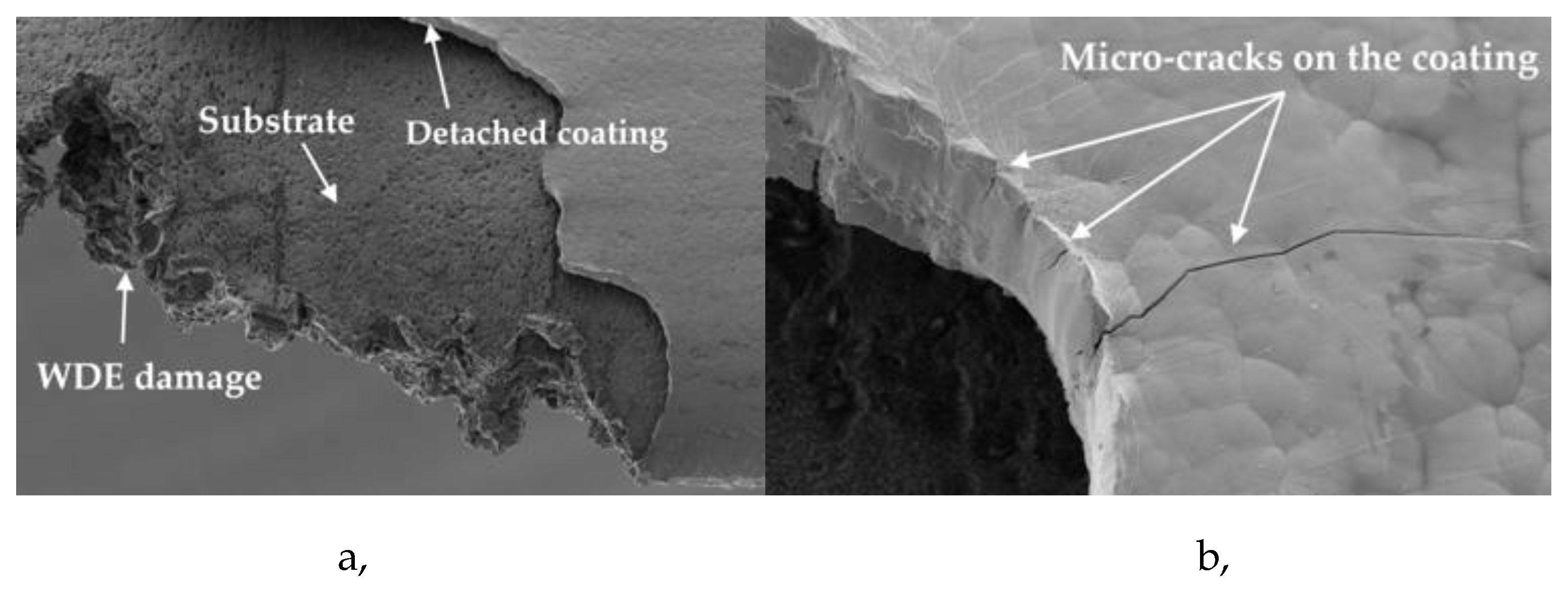
Figure 8.
SEM image of Sample 3 after 2,5x10^8 collided water droplet: (a), increased surface roughness (resolution: x300); (b), coating structure (resolution: x318).
Figure 8.
SEM image of Sample 3 after 2,5x10^8 collided water droplet: (a), increased surface roughness (resolution: x300); (b), coating structure (resolution: x318).
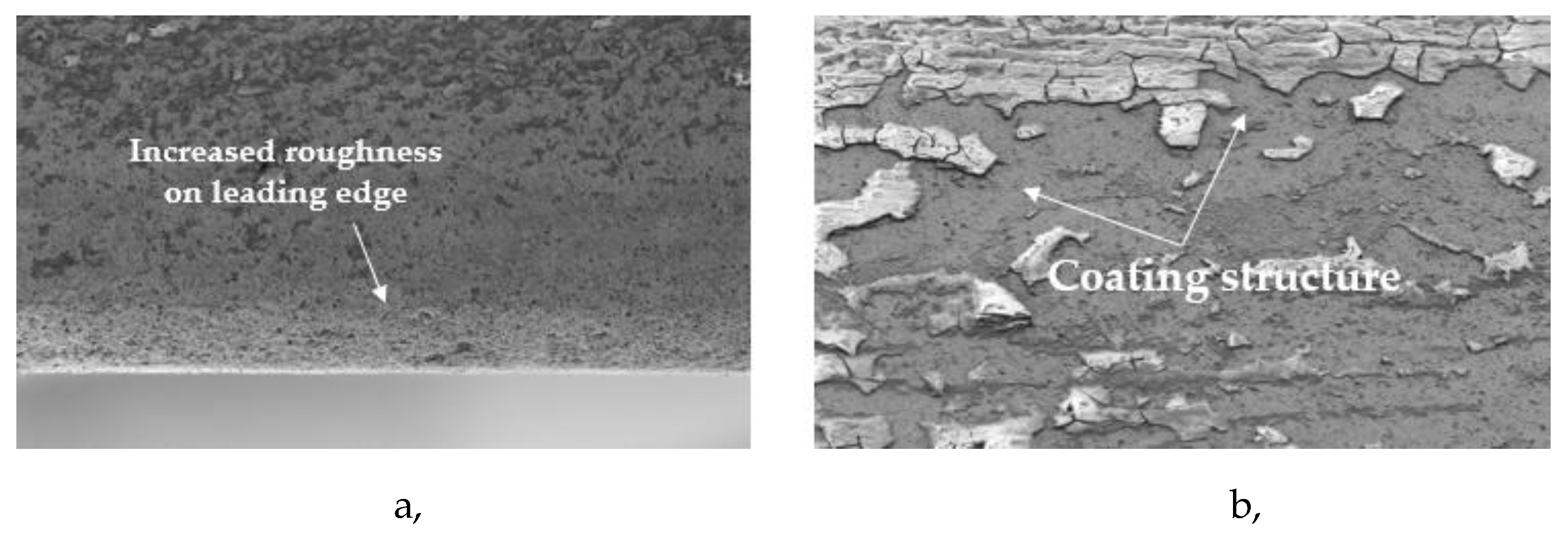
Figure 9.
SEM image of Sample 3 after 9,72x10^8 collided water droplet: (a), WDE (water droplet erosion) on the impeller (resolution: x81); (b), crack free coating (resolution: x2750).
Figure 9.
SEM image of Sample 3 after 9,72x10^8 collided water droplet: (a), WDE (water droplet erosion) on the impeller (resolution: x81); (b), crack free coating (resolution: x2750).
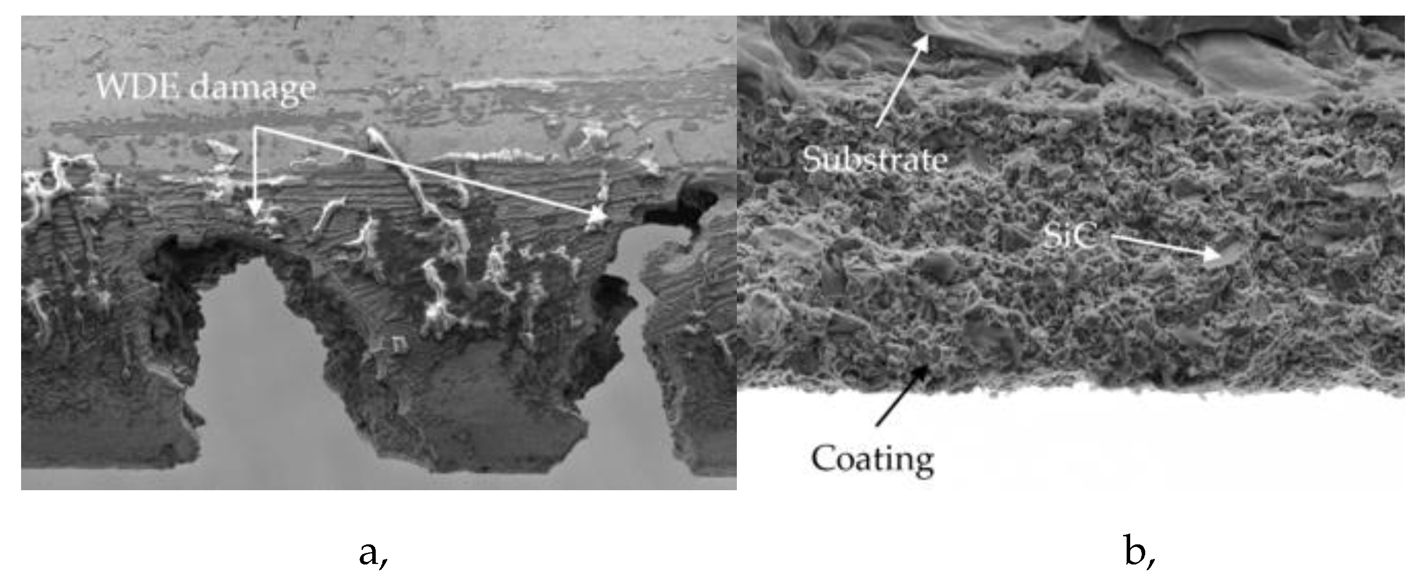
Figure 10.
Isentropic efficiency comparison of the original and the eroded compressor impeller with Sample 1 coating. Speed line 1 was at 150 m/s, speed line 2 was at 200 m/s, speed line 3 was at 250 m/s. .
Figure 10.
Isentropic efficiency comparison of the original and the eroded compressor impeller with Sample 1 coating. Speed line 1 was at 150 m/s, speed line 2 was at 200 m/s, speed line 3 was at 250 m/s. .
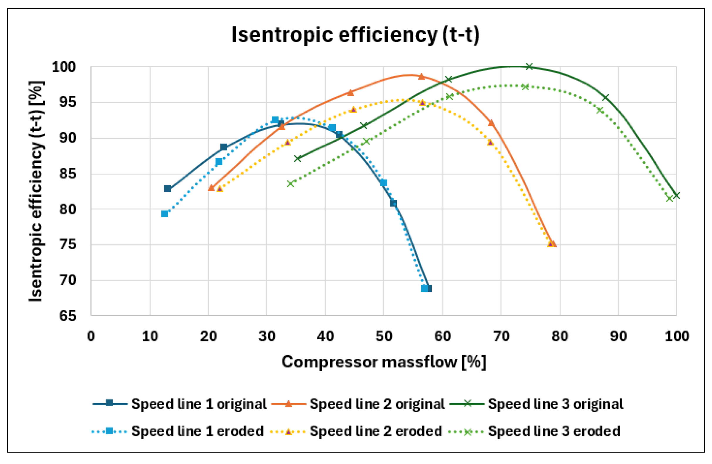

Table 1.
Hardness values of the samples’ base material and coating.
| Sample 1 | Sample 2 | Sample 3 | |
| Hardness of base material [HV10] | 145 | 146 | 134 |
| Hardness of coating [HV0,05] | 522 | 517 | 616 |
Table 2.
Chemical composition of the samples’ coatings.
| Chemical composition of the coating |
Sample 1 [weight %] |
Sample 2 [weight %] |
Sample 3 [weight %] |
|---|---|---|---|
| C | 40,43 | 24,63 | 30,56 |
| P | 6,4 | 8,8 | 5,42 |
| Ni | 53,17 | 66,57 | 60,38 |
| Si | 0 | 0 | 3,64 |
Disclaimer/Publisher’s Note: The statements, opinions and data contained in all publications are solely those of the individual author(s) and contributor(s) and not of MDPI and/or the editor(s). MDPI and/or the editor(s) disclaim responsibility for any injury to people or property resulting from any ideas, methods, instructions or products referred to in the content. |
© 2025 by the authors. Licensee MDPI, Basel, Switzerland. This article is an open access article distributed under the terms and conditions of the Creative Commons Attribution (CC BY) license (http://creativecommons.org/licenses/by/4.0/).
Copyright: This open access article is published under a Creative Commons CC BY 4.0 license, which permit the free download, distribution, and reuse, provided that the author and preprint are cited in any reuse.


