
Submitted:
21 May 2025
Posted:
23 May 2025
You are already at the latest version
Abstract
The dynamic control of vibrations in skyscrapers is a critical consideration in sustainable building design, particularly in response to environmental excitations such as wind impact or seismic activity. Effective vibration neutralization plays a crucial role in providing safety in the damping/attenuation of high-rise structures. This research introduces an innovative concept for an active vibration damper, which operates on the basis of fluid dynamic transport to adaptively alter a skyscraper’s natural frequency, thereby counteracting resonant vibrations. The damper design consists of interconnected liquid reservoirs, where fluid displacement is actively controlled in response to acceleration signals, enabling real-time precise adaption of the building’s dynamic behaviour. A comprehensive mathematical model based on Lagrangian mechanics outlines the governing equations for this system, capturing the interactions between pendulum motion, fluid flow, and the damping forces necessary to maintain stability. Simulation analyses examine the role of initial excitation frequency and variable damping coefficients, revealing critical insights into optimal damper performance under varied structural conditions. Findings indicate that by fine-tuning fluid flow and damping parameters, the proposed damper effectively mitigates resonance risks, paving the way for sustainable skyscraper design through enhanced structural adaptability and resilience. This adaptable fluid-based damper provides a solution for safe, energy-efficient skyscraper designs, aligning with sustainable architectural practices and advancing future trends in vibration management technology. This study supports the development of safe, future-ready, energy-efficient skyscraper technologies.
Keywords:
skyscraper
; pendulum-tuned mass damper
; system dynamics control
; vibration neutralisation
; vibration analysis
; numerical modeling
; frequency spectra
1. Introduction
The interest in studying the dynamic response of civilian structures to environmental excitations such as wind and seismic activity has grown considerably in recent years [1,2,3,4]. Vibrations caused by such phenomena can pose a serious threat to the structural integrity of tall buildings and bridges [5,6]. To mitigate these risks, modern structures increasingly incorporate vibration control systems [7,8,9].
In the context of vibration mitigation, both passive and active systems have been developed and analyzed extensively [10,11,12]. Passive systems, such as tuned mass dampers (TMD), are widely used due to their simplicity and reliability [13,14,15], though they often lack adaptability in real-time conditions [16,17]. Active and semi-active systems have been introduced to overcome these limitations, offering adjustable responses to dynamic changes [18,19,20].
Recent studies have also explored more complex and innovative approaches to structural control, including the use of fluid-based mass systems and adaptive pendulum mechanisms [6,21,22]. These concepts aim to provide higher levels of tuning flexibility, especially for high-rise buildings exposed to varying dynamic loads. The present research introduces a novel active vibration control concept based on controlled liquid mass transportation between two reservoirs [23,24,25]. The goal is to develop a dynamic vibration eliminator where the shift of liquid mass actively adjusts the structure’s natural frequency, enabling it to avoid resonance. This approach builds on previous active damper studies [26,27,28] and incorporates fluid dynamics for intelligent mass redistribution [29,30].
In this concept, a large water tank serves as the primary mass element, with a secondary liquid reservoir suspended like a pendulum beneath it. When resonance is detected through acceleration measurements, the system activates pumps to transfer fluid to a lower position, altering the mass distribution and thereby modifying the dynamic behavior of the structure. If dangerous excitation reoccurs, the liquid is returned to the upper tank to repeat the process, creating an adaptive feedback loop.
To explore the feasibility of this concept, a physical experimental model has been designed. For simplification, components of the structure are treated as rigid bodies, avoiding complications related to internal flexural modes. A CAD model of the test setup is shown in Figure 1. It features a rigid support frame, a suspended mass, and an adjustable-length cable to fine-tune dynamic response. The system is meant to emulate the conditions of real-world damping and validate analytical predictions. It is also established that during the test, mass will be transported from the upper to the lower tank based on the assumed flow characteristic obtained experimentally and then approximated by a mathematical function.
Modern design processes increasingly rely on numerical modeling and simulation to evaluate complex structural behaviors [31]. With the growing power of computational tools, it is now possible to simulate phenomena such as wind and earthquake loads using accurate mathematical functions. This allows for high-quality predictive analysis with minimal cost and time investment.
To avoid dependence on expensive commercial software, many engineering teams develop their own simulation tools based on open-source libraries [32,33,34]. Among the most commonly used are Python-based libraries for symbolic computation and data analysis, including SymPy and Pandas [35,36].
In this study, a custom simulation environment was created using such libraries to model the behavior of the proposed fluid-based tuned mass damper. The simulation employs the Rayleigh damping model to replicate realistic structural damping conditions and determine optimal control parameters for the proposed system.
This work introduces an active vibration control system for high-rise buildings, grounded in the principles of fluid dynamic transport. The system adaptively transfers fluid between connected tanks. A change in mass is considered, which directly affects the effective length of the pendulum damper (PTMD). This results in an adaptive vibration absorber effect, allowing the tuning frequency to be adjusted to the operating conditions by adapting the building’s effective natural frequency in real time. The control mechanism is actuated by acceleration signals, enabling highly responsive damping that prevents resonance under environmental excitations such as wind or seismic activity.
2. Concept of the Investigated System
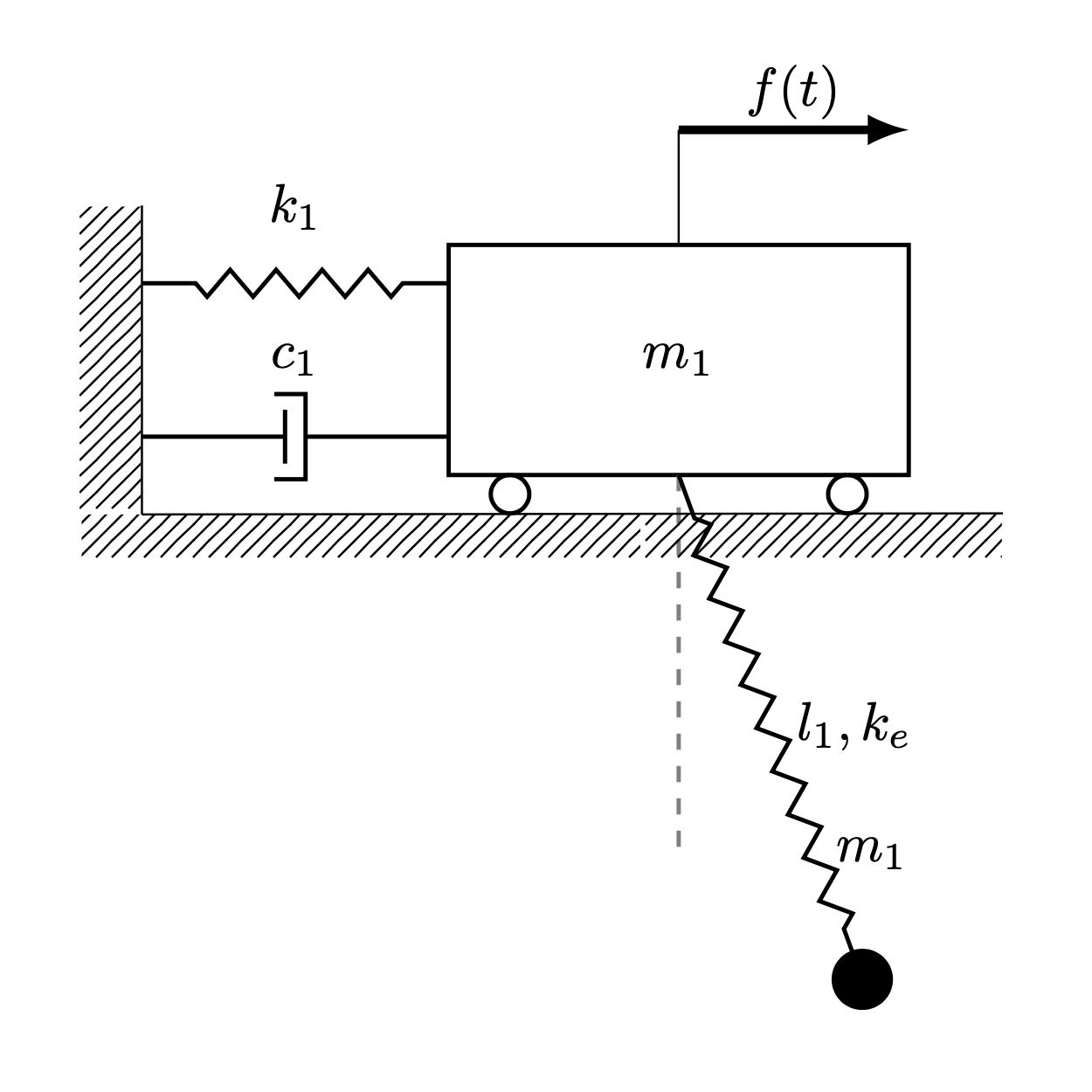
The model of vibration eliminator consists of a trolley attached to the wall by the spring, to which an elastic pendulum is being connected. The trolley is externally forced by a time-varying horizontal force. It was assumed that in the initial phase all the liquid is inside the trolley. Activation of the damping will be done by initiating the transportation of liquid into the pendulum.
An explanatory figure of the selected concept is presented in the Figure 2.
3. Model Analysis and Governing Equations
To analyze the dynamic behavior of the proposed system, the equations of motion were derived using the Lagrangian formulation, which is expressed in general form as:
where:
- - system’s potential energy;
- - system’s kinetic energy.
The specific expressions for the potential and kinetic energies are as follows:
where:
- u
- - pendulum’s elongation;
- t
- - time;
- l
- - pendulum’s length;
- k
- - spring’s stiffness;
- - mass of the pendulum;
- - pendulum’s swing angle;
- - pendulum’s stiffness;
- g
- - gravity constant;
- x
- - trolley’s displacement.
- - pendulum’s elongation velocity;
- - trolley’s velocity;
- - mass of the trolley;
- - pendulum’s swing angular velocity.
From the Lagrangian function, the Euler–Lagrange equations are applied to derive the full set of equations of motion. These are given below:
where:
- - trolley’s acceleration;
- - pendulum’s elongation acceleration;
- F
- - excitation force;
- Ω
- - excitation frequency;
- - pendulum’s swing angular acceleration.
Equations (5)–(7) together form a system of nonlinear, coupled differential equations that comprehensively describe the dynamics of the investigated object. Due to their complexity and nonlinear nature, analytical solutions in the general case are not feasible. Therefore, to facilitate further analysis and enable efficient simulation, the system was linearized around a selected operating point.
The linearized model describes the dynamics in the neighborhood of this equilibrium and is given by the following equations:
These linearized differential equations (8-10) describe the system’s response under small perturbations around the equilibrium state. The resulting system is linear with constant coefficients.
The structure of the equations also reveals partial coupling: equations (8) and (9) form a coupled subsystem that must be solved simultaneously, whereas Equation (10) is decoupled and can be treated independently as a parametric input for the remaining system.
This decomposition significantly simplifies further analysis. The linear model allows for the use of analytical methods to find closed-form solutions, enabling precise interpretation of the system’s dynamic behavior and facilitating parametric studies under varied excitation conditions.
The system is excited by the kinematic force, acting on the trolley, in form of harmonic function below(11):
After substituting individual parameters into the linearized equations of motion, matrices of inertia (12), stiffness (13) and damping (14) were determined.
where:
b - damping coefficient.
The presented analysis describes the proposed model and the methodology used to determine the system’s equations of motion for the non-linearized and linearized dynamics of the dynamic system of the trolley and the pendulum. On this basis, the numerical solutions were divided and presented in the next part of the paper. It is assumed that the pendulum’s movement does not affect the flow of the liquid through the pipe. The equation describing it, including previous assumption, has the form (15):
where:
- activation time;
- flow coefficient;
- flow function.
On the basis of equation above we can derive time variable mass functions of both parts of the system. These equations are (16), (17):
where:
- mass of the fluid.
4. Simulation Results - Investigation of Initial Frequency Influence
The excitation frequency value was verified through simulation. The analysis was conducted using parameters in the vicinity of the calculated natural frequency of the trolley, due to the requirement for the system to operate under resonance conditions. Simulation data was selected within the range of 0.494 to 0.894 Hz. The results are presented in Figure 5 and Figure 6. Based on these plots, the optimal excitation frequency was determined and will be used in subsequent simulations.
The simulations revealed a significant increase in amplitude for the excitation frequency = 0.694 Hz. The observed growth in amplitude suggests that the system is operating within the resonance zone. For the remaining excitation frequencies, the amplitudes exhibit periodic variations within the allowable deflection range for large structures.
The graph of the pendulum’s angular displacement within the excitation frequency range of 0.494 to 0.894 Hz shows a similar amplitude pattern to that of the trolley. Again, a critical increase in amplitude was observed at = 0.694 Hz. Based on these results, this value was identified as the fundamental excitation frequency and will be employed in further simulations.
5. Simulation Results - Investigation of Damping Coefficient Influence
The impact of the damping coefficient on the response of the system under the influence of harmonic excitation is presented in the Figure 7 and Figure 9 graphs and on the Figure 8 and Figure 10 spectra. During the analysis, the values of the damping coefficient selected from the range 80.0 to 120.0 s were considered. This analysis allows to choose the appropriate value of the damping coefficient, which will ensure the system’s stability in the range of real amplitude values.
On the basis of the performed simulations, a significant influence of the tested parameter on the range of amplitudes was observed. It was observed that for the value of the damping coefficient equal to 80.0 s, the system experiences vibrations characteristic for the beating phenomenon after starting the liquid transport. When analyzing the waveforms for subsequent parameters, no sudden changes in amplitudes and gradual stabilization were observed. The extreme values of the amplitudes are in the range -8.33 m to 8.3 m.
The obtained frequency spectra were presented on the Figure 8 graph in order to show the influence of the damping coefficient on the overall amplitude range of the system. From the spectrum plot Figure 8, it can be read that as the damping factor increases, the influence of individual dominant amplitudes decreases. In addition, the decrease in the amplitude values is smaller for higher values of the coefficient, which is associated with a decrease in the system’s sensitivity to mass changes at higher damping values. The maximum amplitude value is 5.42 m.
Analyzing the influence of the damping coefficient on changes of the angle of the pendulum deflection from, a short-term jump in amplitudes was observed at the moment of activation of the transport of liquid from the upper to the lower reservoir. This jump is due to a sharp change in the pendulum dynamics. It was observed that the amplitude jump at low values of the damping coefficient destabilized the system, causing the pendulum to oscillate in a dangerous range (above 15–20∘). The minimum and maximum values are in the range: -0.51 rad to 0.5 rad.
The frequency spectra shown in the Figure 10 graph represent the overall amplitude range when studying the effect of the damping factor . From these spectra, the appearance of two components was observed. The former corresponds to the harmonic resulting from the applied excitation, and the latter to the activation of the liquid flow. It can then be seen that a higher value of the damping coefficient significantly reduces the increase in amplitudes in the transition phase. The maximum value of the component shown in the frequency spectrum is 0.35 rad.
To analyze the selection of the damping coefficient, a simulation was performed without activating the liquid flow, in order to isolate the influence of the damping coefficient on the system dynamics. The analysis was carried out for the damping coefficient b, within the range of 4 to 20 .
In the Figure 11, it can be observed that the first three values of the parameter b — specifically 4, 8, and 12 — are insufficient to suppress the amplitude growth. Stabilization is evident only for higher values of the damping coefficient. A similar trend is observed in the pendulum’s angular displacement in Figure 12. Based on these results, and considering the simulations for both active and inactive dampers with variable mass, it was concluded that the damping coefficient b should be selected from the middle of the tested range. This choice ensures sufficiently high additional damping to mitigate pendulum amplitudes during active mass transport, while avoiding excessive damping that could adversely affect system behavior.
6. Simulation Results - Investigation of Damping Activation Time Influence
The analysis of the damping activation time was performed using a new damping coefficient value, determined based on the previous section’s results. The simulation outcomes are presented in the Figure 13 and Figure 15 and in the frequency spectra Figure 14 and Figure 16. The approach for selecting the appropriate activation time followed the same methodology as in the damping coefficient analysis. The simulations were conducted for activation times ranging from -30 s to 90 s. The objective was to investigate the impact of activation time on the system dynamics, with a focus on both the transient amplitudes during damping mass flow and the steady-state behavior.
Based on the simulation results shown in the plot Figure 13, the influence of the activation time on the overall vibration characteristics of the system can be assessed. Initially, the activation of mass flow had a minimal effect on the trolley displacement; however, a stabilizing behavior was observed shortly afterward. It was noted that earlier activation of the damping mechanism effectively limits rapid resonance propagation. The extreme displacement values recorded during the simulation were -6.86 m and 6.79 m.
The frequency characteristics shown in Figure 14 were used to evaluate the influence of the activation time on the generalized amplitude levels, with maximum values indicated for each spectrum. The spectra reveal that the dominant amplitudes are primarily induced by the excitation frequency. Furthermore, it was observed that early or immediate activation of damping yielded identical results. In contrast, delayed activation led to higher overall amplitude levels. The maximum amplitude value recorded for the latest activation time of 90 s was 4.82 m.
Simulation results illustrating the pendulum’s angular displacement for various damping activation times are presented in Figure 15. In this case, a faster stabilization of vibrations was observed compared to the trolley displacement results in Figure 13. Additionally, it was noted that, regardless of the damping activation time, the system successfully eliminated resonance. Temporary amplitude growth was observed upon activation of the damping mass flow. The minimum and maximum angular displacement values were -0.67 rad and 0.65 rad, respectively.
The frequency spectra presented in Figure 16 illustrate the amplitude distribution of the pendulum’s angular displacement across various damping activation times. Two distinct amplitude components were identified. The first corresponds directly to the excitation frequency and confirms that early damping activation significantly reduces the overall amplitude level. The second harmonic arises from the initiation of the damping mass flow. Notably, delayed activation results in a high transient amplitude, which could adversely affect system performance due to excessive temporary deflections. The maximum average amplitude value recorded was 0.32 rad.
7. Simulation Results - Investigation of Trolley Mass Influence
This section investigates the influence of the trolley mass on the general characteristics of the system’s amplitudes. The simulation results are presented in the Figure 17 and Figure 19, as well as in the corresponding frequency spectra Figure 18 and Figure 20. The considered values of the trolley mass range from 60 kg to 100 kg. Within this range, 5 representative values were selected for simulation purposes.
The plot Figure 17 illustrates the impact of the b parameter on the trolley displacement. It can be observed that insufficient initial mass of the trolley reduces the damping effectiveness of the vibration eliminator once the liquid flow is initiated. The extreme values of the displacement amplitude fall within the range -6.34 m to 6.26 m.
In the frequency domain plot Figure 18, a significant influence of the parameter on the system vibrations can be noted. Specifically, the overall level of trolley vibration amplitudes diminishes for increasing trolley mass values, while the contribution of the frequency component associated with damping activation becomes more pronounced. The highest amplitude level was recorded for the lowest considered trolley mass of 60 kg, with a value of 4.29 m.
The plot Figure 19 presents the pendulum’s angular displacement under harmonic excitation for varying ratios between the trolley and pendulum masses. It is evident that as the trolley mass increases, the instantaneous amplitude spike due to damping activation also becomes more prominent. Moreover, it was observed that achieving a specific final pendulum mass does not guarantee the suppression of trolley resonance. The pendulum deflections range from -0.54 rad to 0.6 rad.
The frequency spectra shown in Figure 20 reveal a shift in harmonic components induced by the activation of the damping mass flow, depending on the initial trolley mass . A lower trolley mass results in vibrations with lower amplitude and higher frequency during damping activation. Additionally, a threshold was identified beyond which further increases in the trolley’s initial mass no longer contribute to elevated amplitude levels induced by damping activation. The maximum generalized amplitude of the pendulum oscillations reached 0.29 rad.
8. Simulation Results - Investigation of Pendulum Mass Influence
The results of the analysis of the influence of the pendulum initial mass on the dynamics of the system are presented on the Figure 21 and Figure 23 and frequency spectra Figure 22 and Figure 24. Simulations were carried out for values from the range 5 kg to 25 kg. The main purpose of the simulation was to select the appropriate mass of the pendulum in order to eliminate the potential rotation with high harmonic excitation.
The graph showing the changes in the position of the trolley depending on the initial mass of the pendulum is shown in the picture Figure 21. While analyzing this graph, the existence of a limit value of the investigated parameter was observed, for which the tested vibration eliminator is not able to compensate for the increase in the amplitude and causes the appearance of vibration modulation. The maximum amplitudes achieved are -5.49 m to 5.51 m.
The frequency spectra of the trolley displacement for different values of the initial mass of the pendulum are shown in the Figure 22. It presents one dominant component resulting from the applied harmonic excitation and a small additional component resulting from the activation of the liquid flow. The graph shows a proportional decrease in the overall level of amplitudes as the initial mass of the pendulum increases. The maximum overall value of the trolley displacement amplitudes is 3.88 m.
By analyzing the Figure 23 plot showing the nature of changes in the pendulum angular displacement depending on the pendulum mass, a characteristic increase in amplitudes was observed during the activation of the liquid flow. In the first moment, the increase in amplitudes is comparable for all tested values of the pendulum’s initial mass. The difference in amplitude is only observed at the next swing, where a heavier-mass pendulum reaches lower amplitudes as expected. The extreme values of the obtained amplitudes are in the range -0.52 rad to 0.57 rad.
The obtained frequency spectra are presented in the Figure 24 graph. They can be used to read the inverse characteristics of changes in the amplitude and frequency of vibrations resulting from the activation of the mass flow to the case of testing the influence of the trolley’s own mass. In this case, it can be seen that as the mass of the pendulum increases, there is a decrease in the amplitude and an increase in the frequency of the vibrations resulting from the activation of the damper. In addition, it was also noted that there is a limit value of the pendulum mass below which the general value of the amplitude resulting from the damping mass flow does not change. The maximum observed amplitude level is 0.26 rad.
9. Simulation Results - Investigation of Transferred Fluid Mass Influence
The results of the research on the influence of the mass of the transported liquid on the overall dynamics of the system are presented in plots in the time Figure 25 and Figure 27 and frequency Figure 26 and Figure 28. The presented results were obtained during the simulation for a parameter in the range 50 kg to 90 kg. The main purpose of the simulation was to examine the effect of the amount of liquid poured on the damping efficiency, and specifically to examine the amplitude values during the transient state and steady state vibrations.
The simulations carried out present the influence of the mass of the transferred liquid on the general level of trolley displacement amplitudes. Based on the presented results, it can be concluded that the appropriately selected mass of transferred water prevents the development of resonant vibrations of the tested pendulum system. Figure 25 Plot shows the system’s immediate response after starting water transfer. In addition, it can be observed that the predetermined amount of transferred liquid adequately dampens the vibrations, without large disturbances during the activation of the damper. The maximum and minimum values of the trolley amplitudes are in the range -6.41 m to 6.26 m.
The obtained frequency spectra presented in the Figure 26 graph show the influence of the transported mass on the general level of vibration amplitudes of the system. The results of the spectral analysis are shown in the form of comparative graphs in the frequency domain. It can then be seen that there is a boundary value of the transferred mass below which no significant decrease in amplitudes is observed during resonance. In addition, a negligible effect of liquid transport on the overall level of system amplitudes was observed, which is represented by a small second component of the spectrum. In this case, the maximum overall amplitude level is 4.41 m.
The obtained Figure 27 plot shows the influence of the mass of the transferred liquid on changes in the angular displacement of the pendulum. The graph shows a very large influence of the examined parameter on the dynamics of the pendulum. The appearance of the limit value was noticed, for which the deflection at the moment of activation of the damping reaches the highest value. In addition, the appearance of an additional significant component was observed at higher values of the transfered mass. The extreme values of the trolley amplitudes are in the range -0.55 rad to 0.61 rad.
By analyzing the frequency spectra shown in the Figure 28 graph, a two-fold decrease in the general level of pendulum amplitudes was observed for cases with extreme values of the transferred liquid. In addition, when analyzing the second component of the amplitudes, it was observed that the amount of transferred mass must be carefully selected due to the non-linear relationship between the amount
10. Simulation Results - Model Validation
The mathematical model representing the trolley and pendulum system and the variable mass model have been parameterized. Parameter values were selected empirically based on the results of preliminary calculations. In addition, the applied load was estimated according to the inputs acting on real structures. In order to verify the correct operation of the proposed mathematical model, tests were carried out with the parameters adopted for the excitation frequency close to the trolley’s natural frequency, beyond it, and the damping activation time greater than the duration of the simulation. In addition, a system without a function simulating a mass change with identical parameters was tested. This system is widely known in the literature, which means that it can be a basis for confirming the correct operation of more complex concepts. The results of both simulations were compared and presented in the Figure 29 and Figure 30 plots.
The Figure 29 and Figure 30 plots of the design test results show complete agreement for the two different excitation types. This consistency was achieved by not activating the damping, so the system behaved as if the vibration eliminator had not been implemented. These results then confirm the correct operation of the system, thanks to which further research can lead to reliable conclusions.
11. Test Stand
A test stand must be set up to verify the research concept and the results of the computer simulation-based research. A block diagram of the test stand and the DAQ system is shown in Figure 31.
The test system being tested is located in a movable reference system. The forcing should be considered (treated) as kinematic. A laboratory stand (Figure 32) available at the Faculty of Automotive and Construction Machinery Engineering of the Warsaw University of Technology was used for experimental research. This stand’s principle is based on oscillatory movement. The tested object is connected to a forcing system.
The test stand consists of several key elements:
- Induction electric motor - source of mechanical energy.
- Inverter - allows the regulation of the motor’s rotational speed, which translates into the frequency of the applied force.
- Crank shaft enabling the conversion of rotary motion into reciprocating motion.
- Connecting rod - connecting the crank with the carriage.
- Carriage on which the tested object is fixed and moves along linear guides.
- Test stand frame - stable supporting structure on which all elements are fixed, ensuring proper working conditions and safety.
- A flexible frame with a weight attached to a thread is the test object; the weight is attached to the thread, which makes it possible to tune the resonance frequencies.
- The measuring system consists of two accelerometers for measuring vibrations and a signal acquisition conditioning unit.
The test stand’s operation principle is as follows: An electric motor drives the test setup via a drive train. The motor’s rotational speed can be adjusted using an inverter. During operation, vibrations are generated, which are transferred to the pendulum frame. Due to these vibrations, thes to oscillate pendulum inside the frame begin. The pendulum can be lengthened or shortened, which translates into the resonance frequencies of the system under test. The test stand allows for the analysis of the dynamics of a vibrating system, including the investigation of the influence of external forces on the oscillations of a pendulum system and the vibration diagnosis of a structure such as a test object, which consists of a frame and a pendulum attached to it. The vibration level of the frame and pendulum is recorded by accelerometers, which are mounted at appropriate points on the frame. A data recording system processes the signals from the accelerometers. This makes it possible to analyze the intensity and characteristics of the vibrations. The operating parameters of the test object on the test stand can be adjusted. This involves controlling the engine via an inverter, which sets the appropriate rotational speed. This way, the influence of different rotational speeds on the generated vibrations and the pendulum’s behavior can be examined.
12. Empirical Study on a Physical Model
The measurement system was configured and set up as shown in Figure 33. The key acquisition components (Figure 34) are the data acquisition (NI cDAQ-9174) and the measurement card (NI 9230).
It was decided to use a system with an inertial mass based on two flat springs. In accordance with the analysis of linearised equations of motion, the flexible pendulum was replaced with a rope of variable length.
Three test scenarios were considered:
- Tests in which the pendulum length was constant (steady state).
- Tests in which the length of the rope was variable and the tension force acted in a plane perpendicular to the direction of motion.
- Tests in which the tension force was applied in the vertical direction.
The influence of the tension force, the mass of the TMD, and the possibility of active vibration damping by changing the length of the rope in a quasi-static manner were evaluated.
The following results were obtained from the stand tests. The results obtained during measurements on the physical model with the application of excitation by setting initial conditions. The excitation was introduced by imposing successive measured values of the initial displacement of the structure.
In the absence of a pendulum, the vibrations exhibit characteristics typical of underdamped oscillations as seen in Figure 35. The acceleration amplitude decreases gradually, leading to prolonged exposure to vibration amplitudes that may be detrimental to the structural integrity.
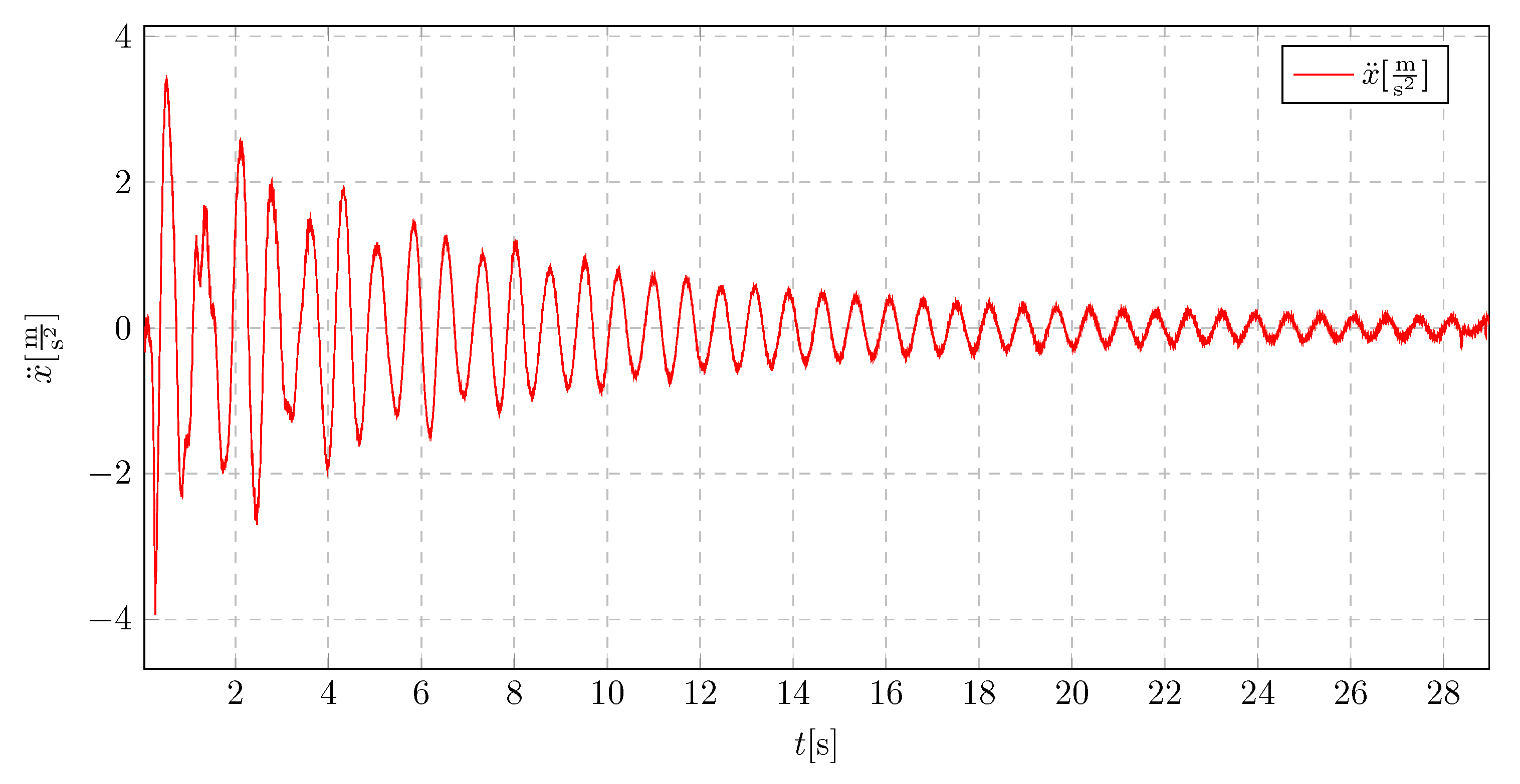
When a pendulum of 25 in length is implemented with an initial displacement of 8 , which is presented in Figure 36, an increased initial acceleration amplitude is observed, which directly results from the initial conditions. Despite the higher initial amplitude, a significant improvement in vibration damping is evident. The damping effect occurs much faster compared to the model without a vibration absorber, even though the initial displacement is larger.
As shown in Figure 37, the vibration characteristics of a 5 cm initial displacement are similar to those observed for an 8 cm displacement (Figure 37). A notable improvement is also evident compared to the structure without a vibration damping system.
Reducing the pendulum length to 15 demonstrates a considerable enhancement in the damping characteristics of the oscillations,(Figure 37). The acceleration values exhibit irregular behavior, with significant reductions occurring approximately every three oscillation periods. The natural period of the structure has also been reduced.
Reducing the initial displacement to 5 does not introduce significant changes in the acceleration characteristics which is shown in Figure 39. The vibration absorber continues to operate in a similar manner.
A pendulum length of 10 (Figure 40) proved to be the optimal solution for the presented high-rise building model. The acceleration characteristics indicate not only a substantial reduction in acceleration amplitude for approximately half of the oscillations but also a further increase in the oscillation period compared to the 15 pendulum length.
Further reduction of the pendulum length led to a decrease in the effectiveness of the vibration absorber as seen in Figure 41. The shortening of the suspension cable was also constrained by the mounting method and the size of the attached pendulum mass.For further development o the measuring station changing attachment point to optimal can be applied. Also there is improvement in progress, which goal is to apply possibility of dynamic changes of length of the cable during proceeded measuring series.
13. Conclusions
To answer the challenge of damping the vibrations of civilian structures the model of active damper was introduced, working on the principles of controllable mass redistribution. The proposed system consists of upper and lower liquid reservoirs connected in a way enabling transport of the water between them. In response to propagation of resonance the system would start to transport the liquid. The change in parameters of the system, impacts its nominal frequency making it less susceptible to external excitations. The simplified scheme with three degrees of freedom (trolley-elastic pendulum) have been created. Its equations of motion were derived with the use of Lagrange mechanics and become the initial point for the main analysis. The parameters of the system, enhancing its properties, were found by simulations of its behavior. This involves the nominal frequency of the system, masses of separate elements and liquid, activation time of the damping and its value. The operation of an active vibration damper was approximated by the flow function of the liquid based on actual measurements. All the work was carried out in a Python based environment developed according to the idea of object-oriented programming. The validation of all the research was done by building the physical model. Crucial outcomes of the work:
- There is a convergence between displacement of a carriage and a pendulum under varying harmonic excitation.
- Selecting the correct value of damping coefficient involves avoiding an overriding contribution from booster dampers, limiting pendulum swing angles, and maximizing the damping rate of resonant vibrations.
- Activation time of fluid flow significantly affects the propagation of resonant vibrations. Early activation is essential to prevent damage to the structure. The system can resemble a classical dynamic vibration eliminator when fluid flow starts before resonance.
- There is a direct relationship between cart mass and pendulum response during liquid flow activation.
- An improper mass ratio between cart and a pendulum can result in diagnostic limitations and excessive pendulum amplitudes and damage of the structure.
- There exist a need for higher tare weights to limit amplitudes to a safe range, contrary to initial assumptions.
- Small pendulum masses can lead to modulation of carriage vibrations due to inadequate damping.
The proposed model of an active vibrations’ eliminator aims to answer the problem of vibration in civilian structures (e.g. skyscrapers) and expands the current state of knowledge in the field. However, the study was limited by a simplification in creating the model of the system the results show the opportunities of using the active liquid distribution in the structure as a way of changing its natural frequency and avoiding resonance phenomenon. To properly compare the data from the theory the built of more advanced physical model would be required. In conclusion, this study demonstrates the potential of precise, active control over the mass distribution in the system as a way of protecting the structure from dangers of external excitations.
References
- Bankar, V.; Aradhye, A. A Review on Active, Semi-active and Passive Vibration Dampin. International Journal of Current Engineering and Technology 2016, 6. [Google Scholar] [CrossRef]
- Allien, J.; Kumar, H.; V. , D. Semi-active vibration control of SiC-reinforced Al6082 metal matrix composite sandwich beam with magnetorheological fluid core. Proceedings of the Institution of Mechanical Engineers Part L-Journal of Materials-Design and Applications 2019, 234, 408–424. [Google Scholar] [CrossRef]
- Kumar Kishore, K.; Krishna, Y. Damping in beams using viscoelastic layers. Proceedings of the Institution of Mechanical Engineers Part L-Journal of Materials-Design and Applications 2013, 234, 117–125. [Google Scholar] [CrossRef]
- Eke, F.; Mao, T. On the Dynamics of Variable Mass Systems. International Journal of Mechanical Engineering Education 2002, 30, 123–137. [Google Scholar] [CrossRef]
- Xu, B.; Xiang, C.; Yechen, Q.; Peng, D.; Mingming, D. Semi-Active Vibration Control for in-Wheel Switched Reluctance Motor Driven Electric Vehicle With Dynamic Vibration Absorbing Structures: Concept and Validation. IEEE Access 2018, 6, 60274–60285. [Google Scholar] [CrossRef]
- Demetriou, D.; Nikitas, N. A Novel Hybrid Semi-Active Mass Damper Configuration for Structural Application. Applied Sciences 2016, 6, 1–18. [Google Scholar] [CrossRef]
- Guimarães, J.; dos Reis Farias, M.; César, M.; Carneiro de Barros, R. Dynamic Analysis of Wind Tower and Dimensioning of Tuned Mass Damper. Revista de Engenharia e Pesquisa Aplicada 2021, 6. [Google Scholar]
- Pais, T.; Boote, D. Developments of Tuned Mass Damper for yacht structures. Ocean Engineering 2017, 141, 249–264. [Google Scholar] [CrossRef]
- Zheng, L.; Zixin, W.; Sami, F.; Xilin, L. Particle impact dampers: Past, present, and future. Structural Control and Health Monitoring 2017, 2058. [Google Scholar] [CrossRef]
- Diez-Jimenez, E.; Rizzo, R.; Gómez-García, M.; Corral-Abad, E. Review of Passive Electromagnetic Devices for Vibration Damping and Isolation. Shock and Vibration 2019, 11. [Google Scholar] [CrossRef]
- Lewandowski, R. Reduction of vibration of civil engineering structures. Wydawnictwo Naukowe PWN 2014. [Google Scholar]
- Gao, H.; Wang, C.; Huang, C.; Shi, W.; Huo, L. Development of a Frequency-Adjustable Tuned Mass Damper (FATMD) for Structural Vibration Control. Shock and Vibration, Hindawi 2020, 2020. [Google Scholar] [CrossRef]
- Kawęcki, J.; Masłowski, R. Use of passive, quasi-active and hybrid silencers to reduce seismic and paraseismic vibrations of buildings - overview of solutions. Czasopismo techniczne Civil Engineering, Wydawnictwo Politechniki Krakowskiej 2010, 3-B/2010, 59–67. [Google Scholar]
- Gutierrez Soto, M.; Adeli, H. Semi-active vibration control of smart isolated highway bridge structures using replicator dynamics. Engineering Structures 2019, 186, 536–552. [Google Scholar] [CrossRef]
- Dominguez, A.; Sedaghati, R.; Stiharu, I. Modeling and application of MR dampers in semi-adaptive structures. Computers & Structures 2008, 86, 407–415. [Google Scholar] [CrossRef]
- Ismail, F.; Tanjung, J.; Aruan, S. On the use of a simple tuned mass damper model for reducing the excessive vibration of tsunami evacuation suspension footbridge. MATEC Web of Conferences 2018, 229. [Google Scholar] [CrossRef]
- Elias, S.; Matsagar, V. Wind response control of tall buildings with a tuned mass damper. Journal of Building Engineering 2018, 15, 51–60. [Google Scholar] [CrossRef]
- Khiabani, E.; Ghaffarzadeh, H.; Shiri, B.; Katebi, J. Spline collocation methods for seismic analysis of multiple degree of freedom systems with visco-elastic dampers using fractional models. Journal of Vibration and Control 2020, 26. [Google Scholar]
- Olson, S. An analytical particle damping model. Journal of Sound and Vibration 2003, 264. [Google Scholar] [CrossRef]
- Gagnon, L.; Morandini, M.; Ghiringhelli, G. A review of particle damping modeling and testing. Journal of Sound and Vibration 2019, 459. [Google Scholar] [CrossRef]
- Chuaqui, T.; Roque, C.; Ribeiro, P. Active vibration control of piezoelectric smart beams with radial basis function generated finite difference collocation method. Jouenal of Intelligent Material Systems and Structures 2018, 29, 2728–2743. [Google Scholar] [CrossRef]
- Brockmann, B.; Brecher, C.; Baumler, S. Avoiding chatter by meansof active damping systems for machine tools. Journal of Machine Engineering 2013, 13, 117–128. [Google Scholar]
- Shi, W.; Wang, L.; Lu, Z. Study on self-adjustable tuned mass damper with variable mass. Structural Control Health Monitoring 2017, 25. [Google Scholar] [CrossRef]
- Kwiatkowski, R. The concept of vibration damping of the variable mass assembly. MATEC Web of Conferences 2019, 254. [Google Scholar] [CrossRef]
- Snoun, C.; Trigui, M. Design parameters optimization of a particles impact damper. International Journal of Interactive Design and Manufacturing 2018, 12, 1283–1297. [Google Scholar] [CrossRef]
- Elias, S.; Matsagar, V. Research developments in vibration control of structures using passive tuned mass dampers. Annual Reviews in Control 2017, 44, 129–156. [Google Scholar] [CrossRef]
- Sarkar, S.; Chakraborty, A. Development of semi-active vibration control strategy for horizontal axis wind turbine tower using multiple magneto-rheological tuned liquid column dampers. Journal of Sound and Vibration 2019, 457, 15–36. [Google Scholar] [CrossRef]
- Kamgar, R.; Gholami, F.; Sanayei, H.; Heidarzadeh, H. Modified Tuned Liquid Dampers for Seismic Protection of Buildings Considering Soil–Structure Interaction Effects. Iranian Journal of Science and Technology, Transactions of Civil Engineering 2020, 44, 339–354. [Google Scholar] [CrossRef]
- Ghassempour, M.; Failla, G.; Arena, F. Vibration mitigation in offshore wind turbines via tuned mass damper. Engineering Structures 2019, 183, 610–636. [Google Scholar] [CrossRef]
- Żurawski, M.; Chiliński, B.; Zalewski, R. A Novel method for changing the dynamics of slender elements using Sponge Particles Structures. Advances in Mechanical Testing of Engineering Materials 2020, 13. [Google Scholar] [CrossRef]
- Oliphant, T. Python for Scientific Computing. Computing in Science & Engineering 2007, 9, 10–20. [Google Scholar] [CrossRef]
- PyLaTeX. PyLaTeX 1.3.2 documentation. https://jeltef.github.io/PyLaTeX/current/. Accessed: 2024-05-04.
- GitHub. bogumilchilinski/dynpy. https://github.com/bogumilchilinski/dynpy. Accessed: 2024-05-04.
- Harris, C.R.; Millman, K.J.; van der Walt, S.J.; Gommers, R.; Virtanen, P.; Cournapeau, D.; Wieser, E.; Taylor, J.; Berg, S.; Smith, N.J.; et al. Array programming with NumPy. Nature 2020, 585, 357–362. [Google Scholar] [CrossRef] [PubMed]
- Wes McKinney. Data Structures for Statistical Computing in Python 2010. pp. 56 – 61. [CrossRef]
- Meurer, A.; Smith, C.P.; Paprocki, M.; Čertík, O.; Kirpichev, S.B.; Rocklin, M.; Kumar, A.; Ivanov, S.; Moore, J.K.; Singh, S.; et al. SymPy: symbolic computing in Python. PeerJ Computer Science 2017, 3, e103. [Google Scholar] [CrossRef]
Figure 1.
CAD model of the experimental setup for the pendulatory tuned mass damper (PTMD) with adjustable cable length. The system consists of a rigid frame, a suspended mass, and a tuning mechanism to modify the natural frequency of oscillations.
Figure 1.
CAD model of the experimental setup for the pendulatory tuned mass damper (PTMD) with adjustable cable length. The system consists of a rigid frame, a suspended mass, and a tuning mechanism to modify the natural frequency of oscillations.
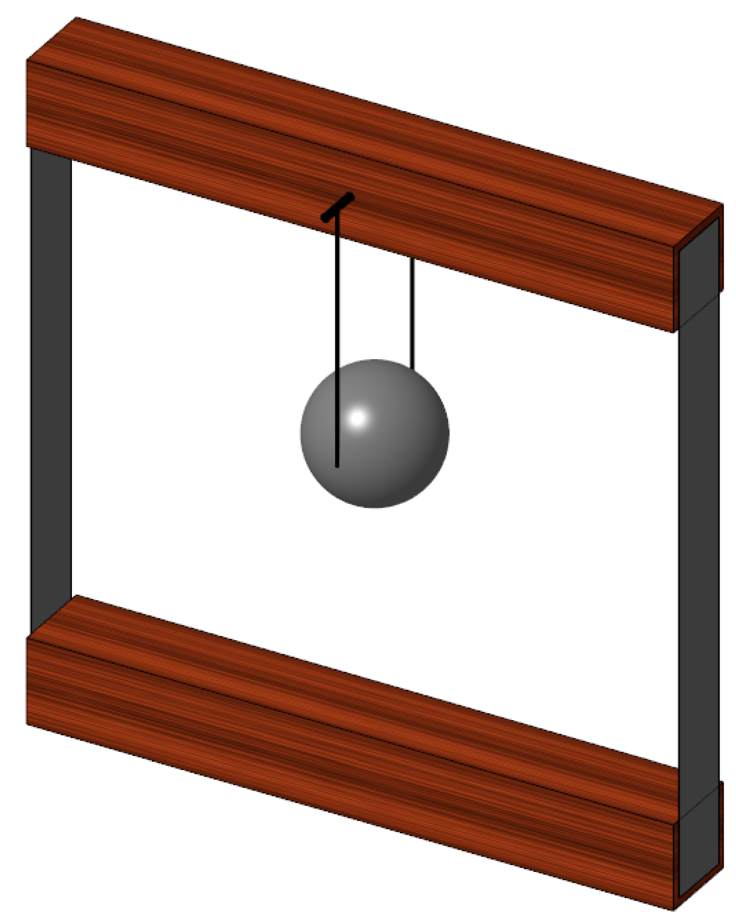
Figure 2.
An explanatory figure of investigated physical model
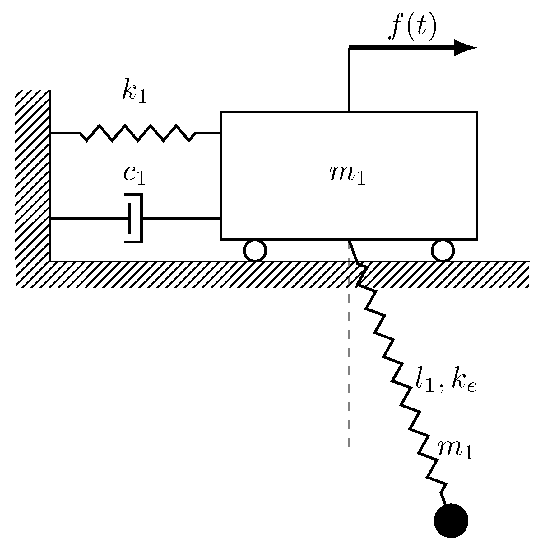
Figure 3.
Liquid flow chart for various flow coefficients
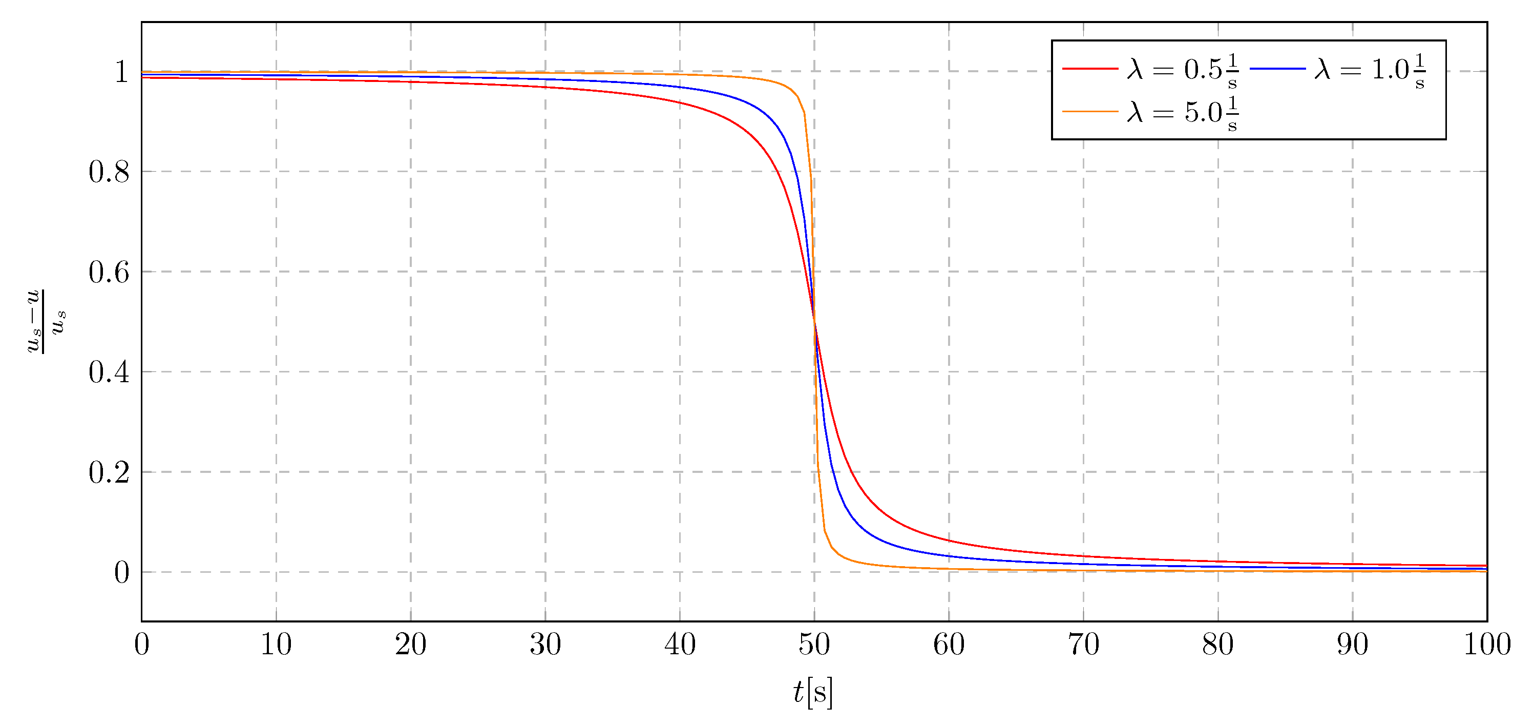
Figure 4.
Liquid flow chart for various damping activation time
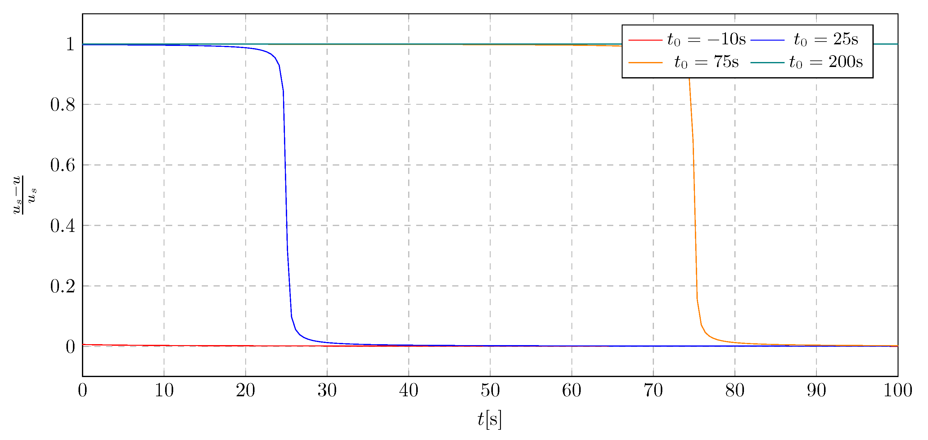
Figure 5.
Trolley displacement for various excitation frequencies
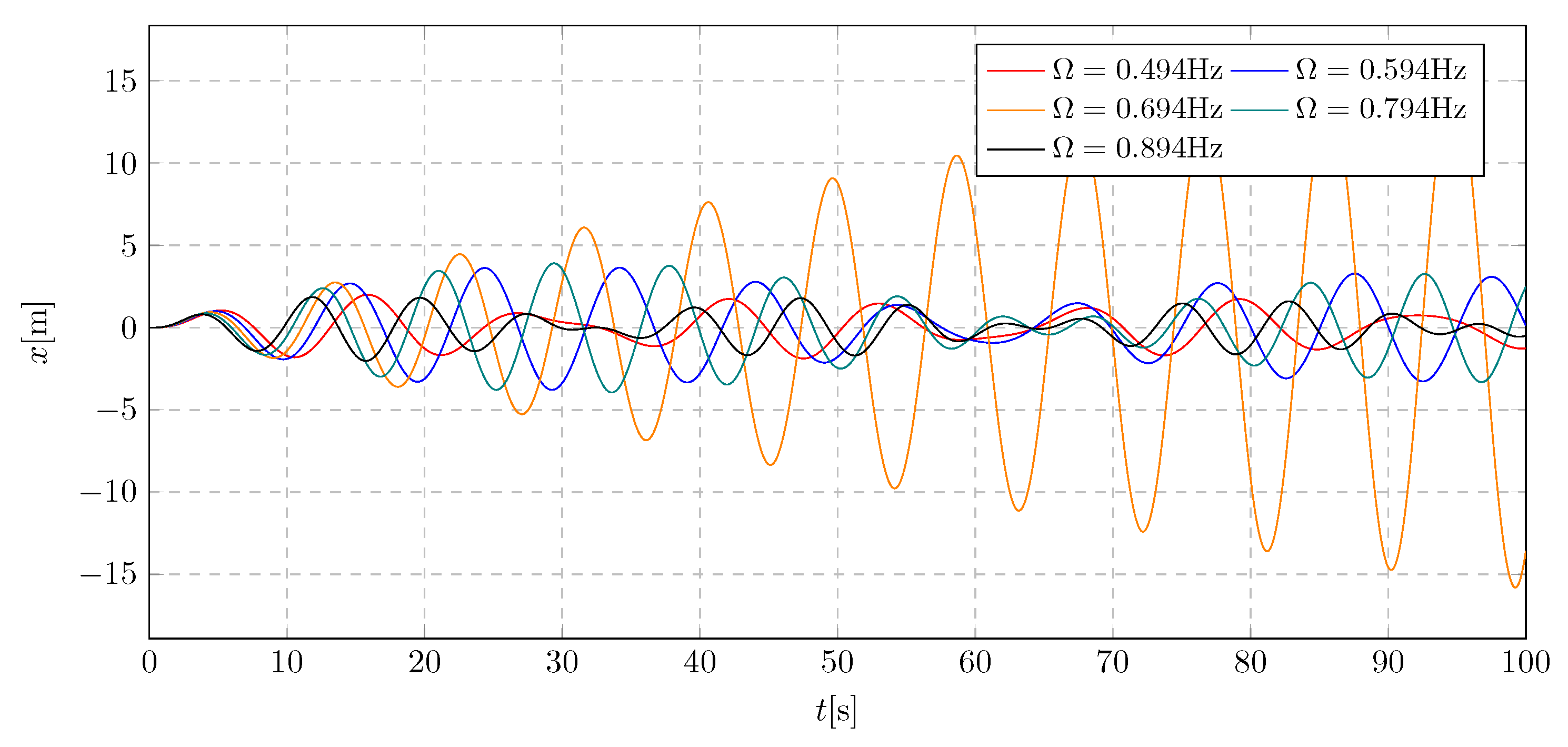
Figure 6.
Pendulum angular displacement for various excitation frequencies
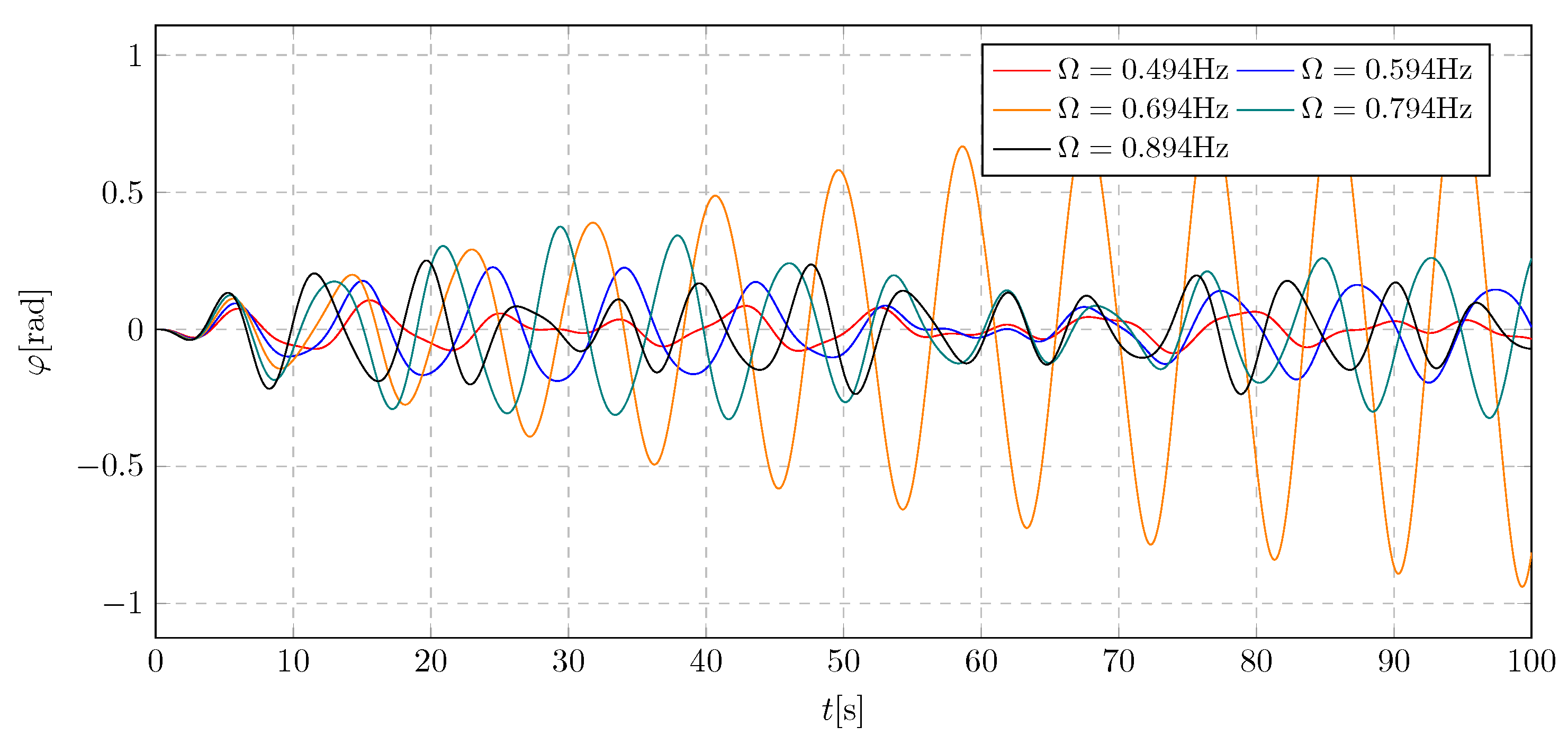
Figure 7.
Trolley displacement for various damping coefficients
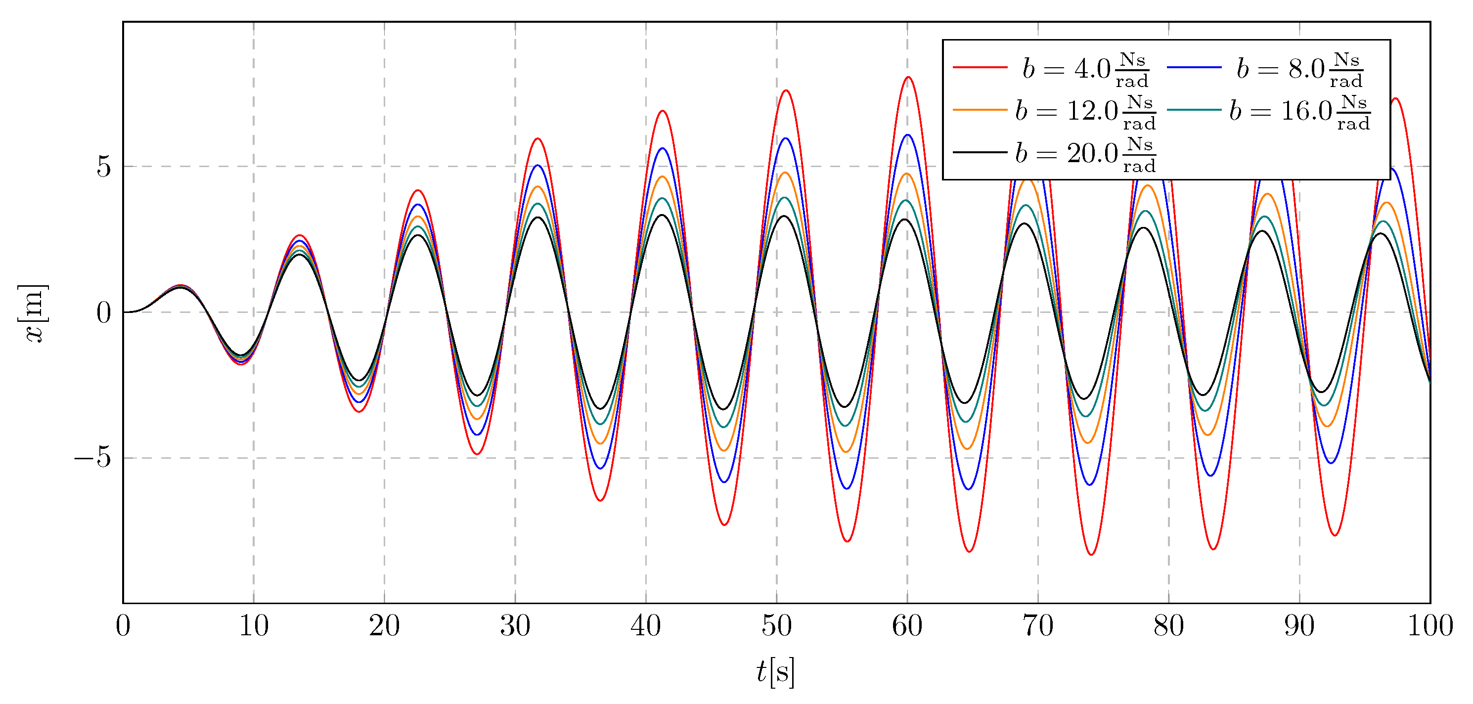
Figure 8.
Frequency spectra of trolley displacement for various damping coefficients
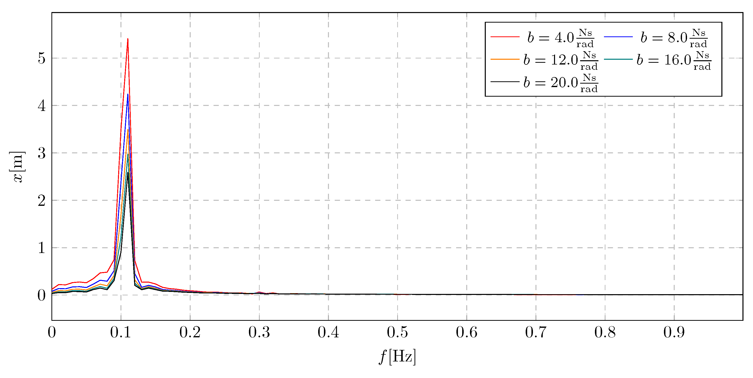
Figure 9.
Pendulum angular displacement for various damping coefficients
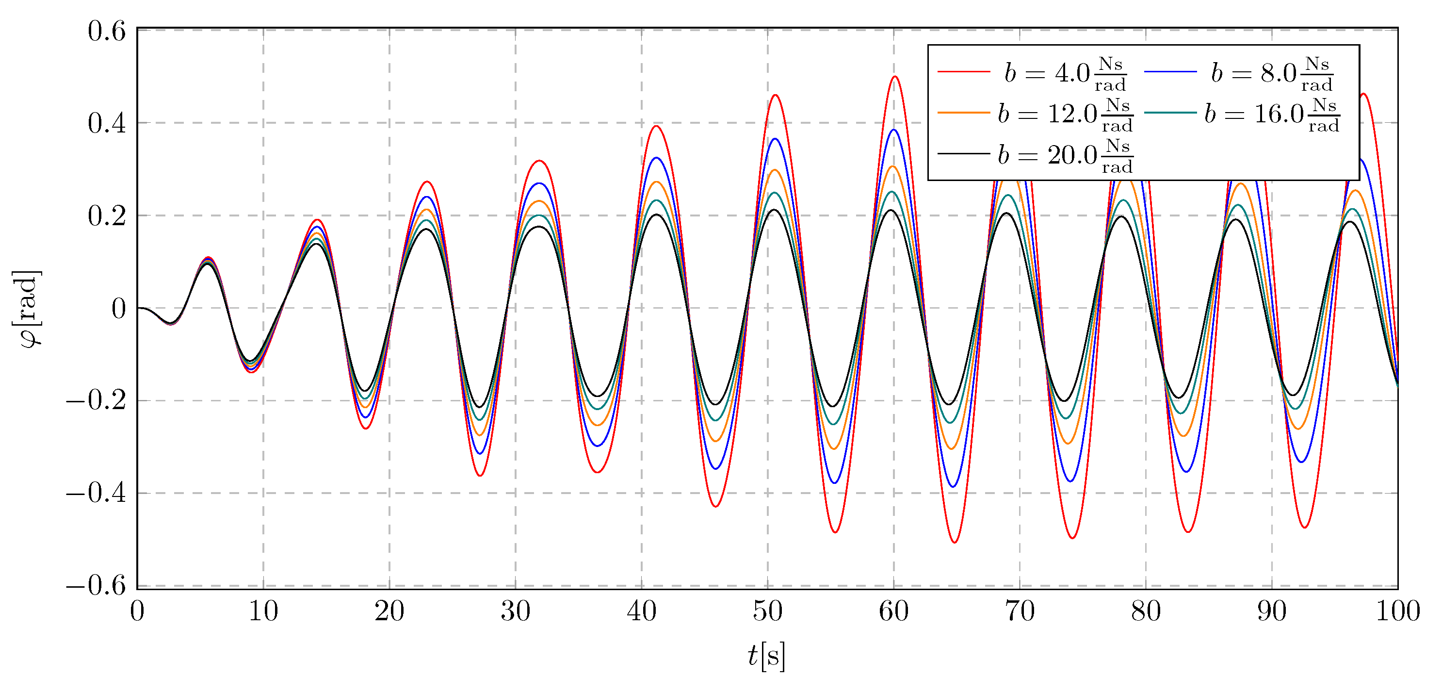
Figure 10.
Frequency spectra of pendulum angular displacement for various damping coefficients
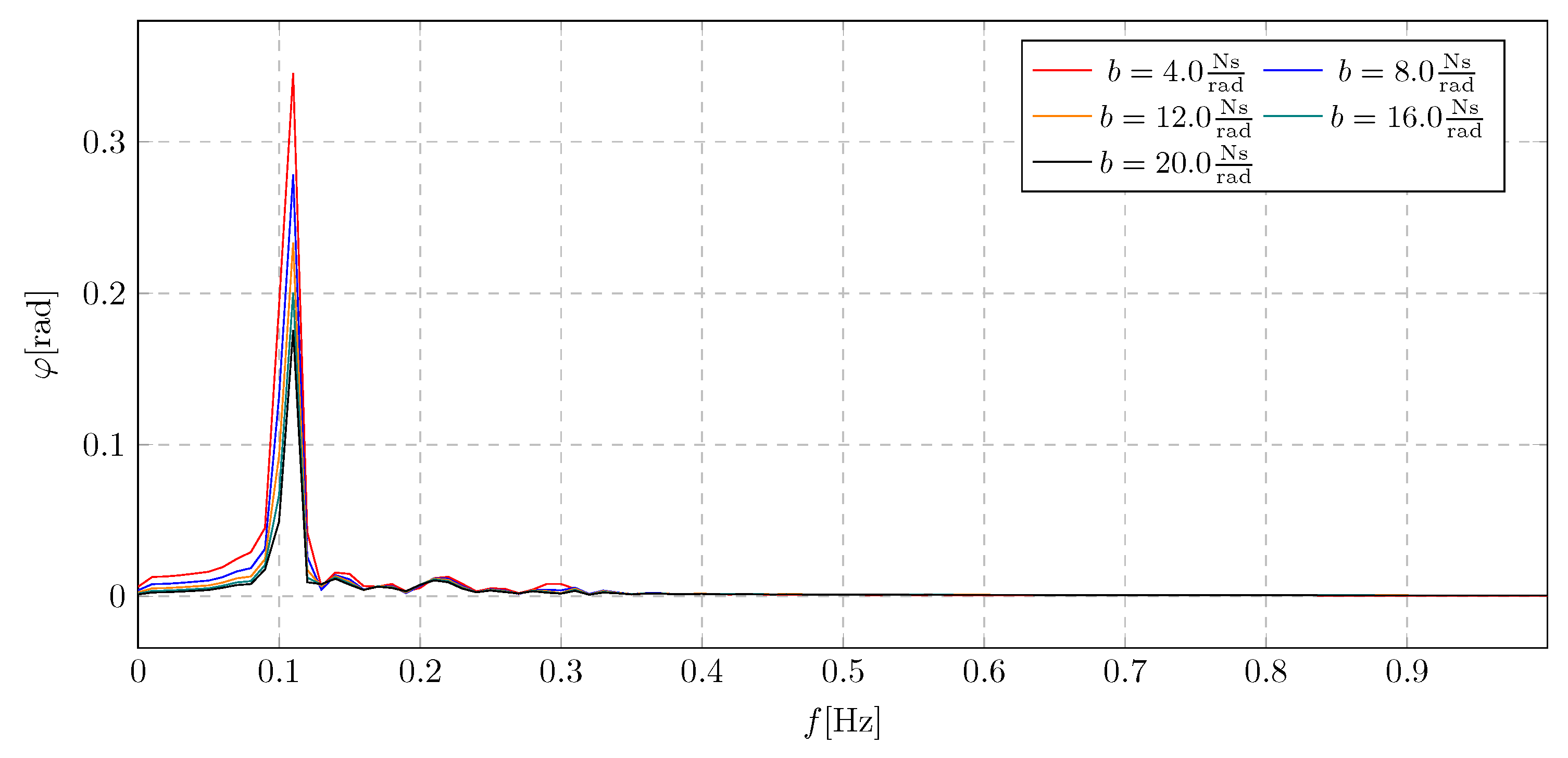
Figure 11.
Trolley displacement for various damping coefficients without damping activation
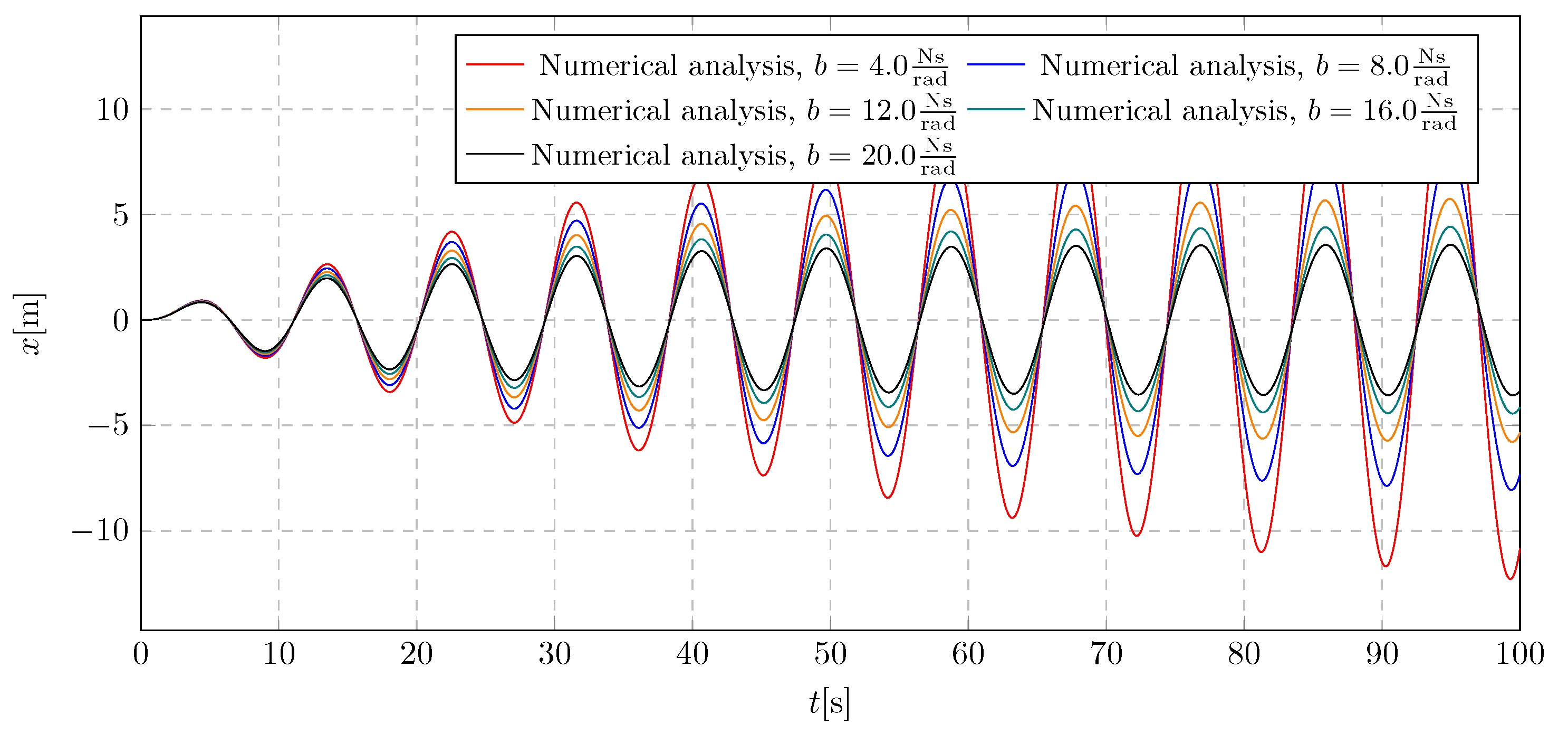
Figure 12.
Pendulum angular displacement for various damping coefficients without damping activation
Figure 12.
Pendulum angular displacement for various damping coefficients without damping activation
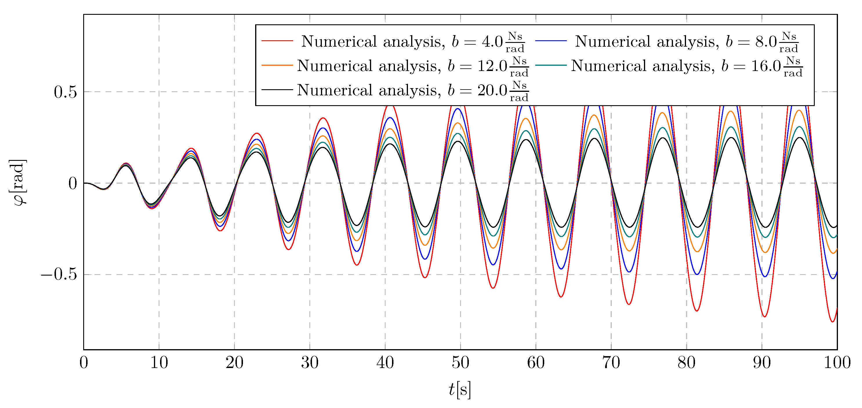
Figure 13.
Trolley displacement for various damping activation time
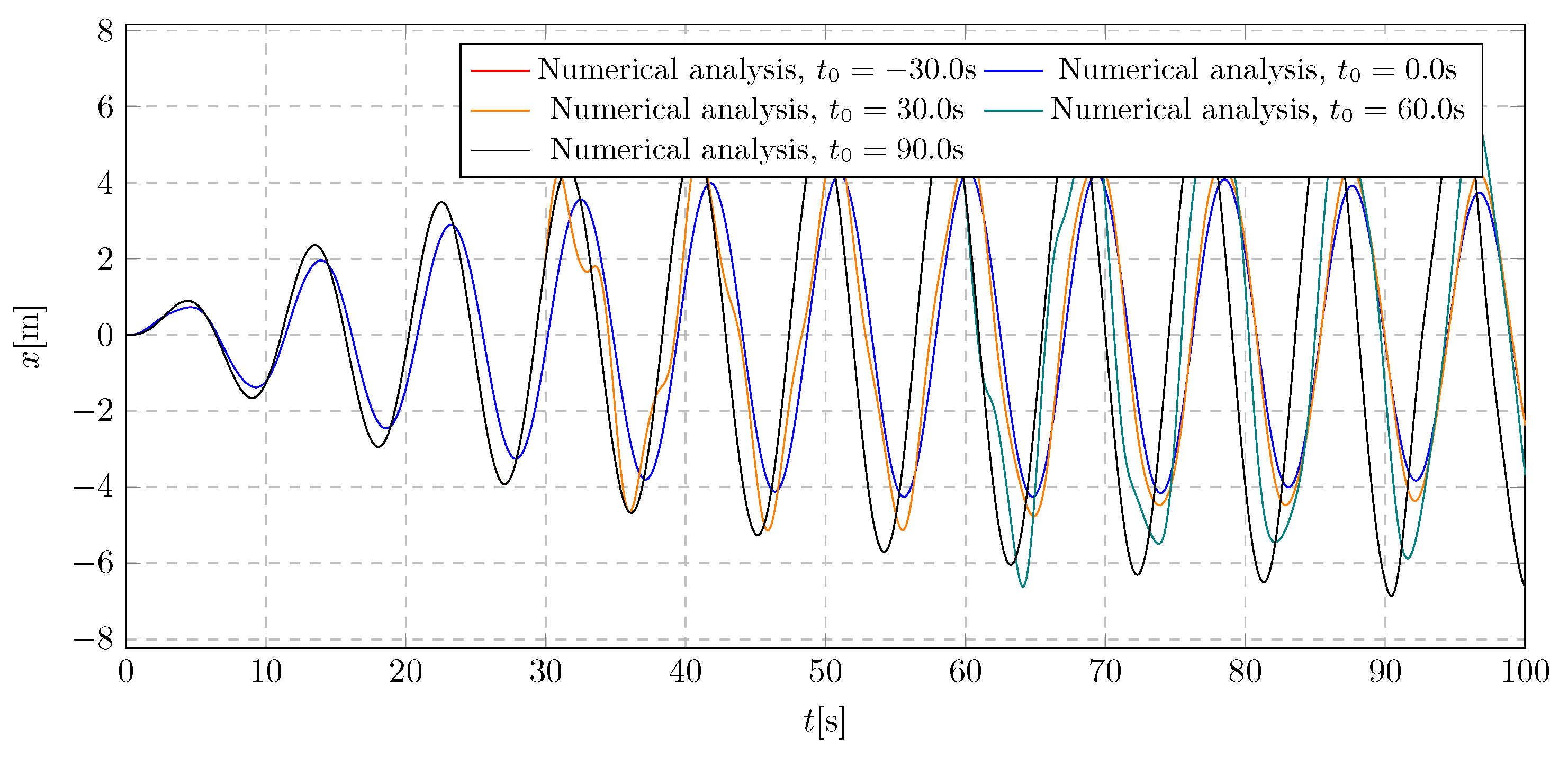
Figure 14.
Frequency spectra of Trolley displacement for various damping activation time
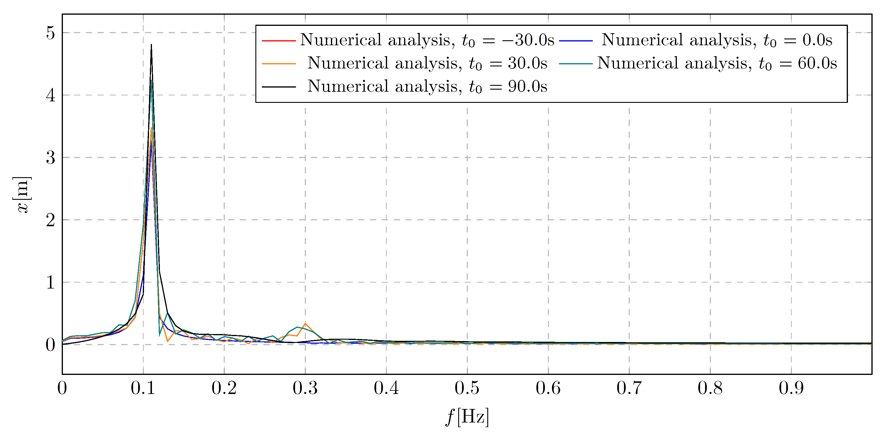
Figure 15.
Pendulum angular displacement for various damping activation time
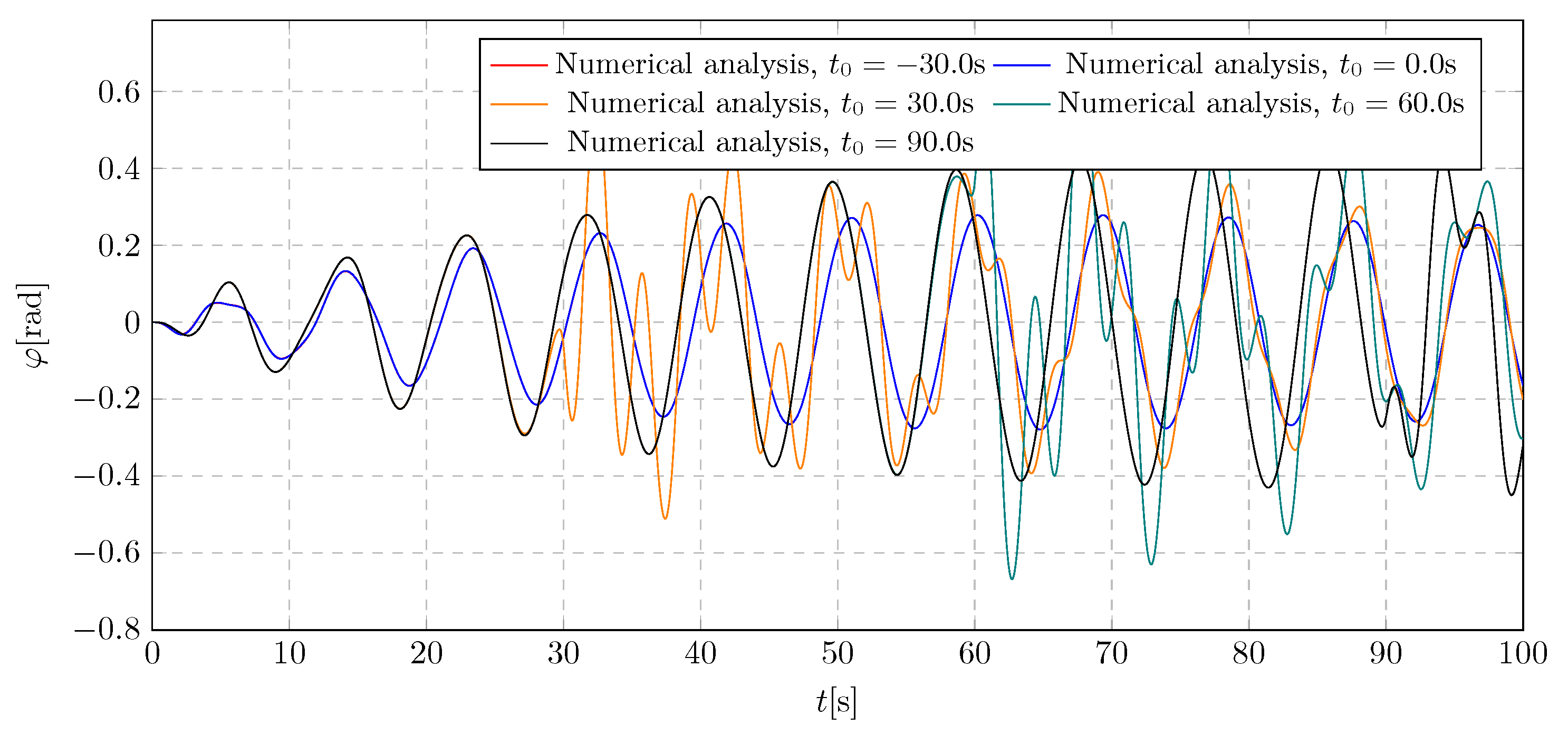
Figure 16.
Frequency spectra of pendulum angular displacement for various damping activation time
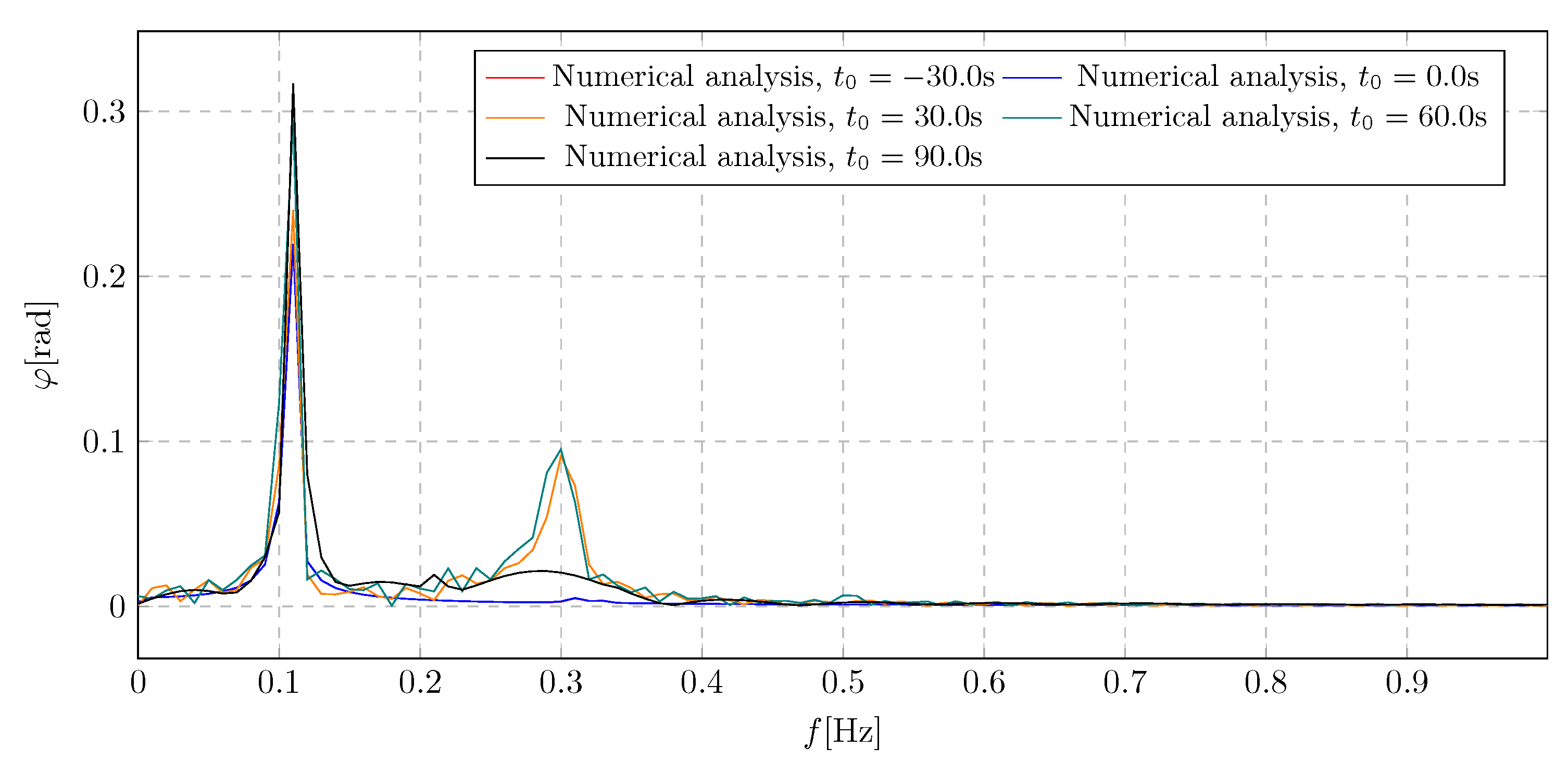
Figure 17.
Trolley displacement for various trolley initial masses
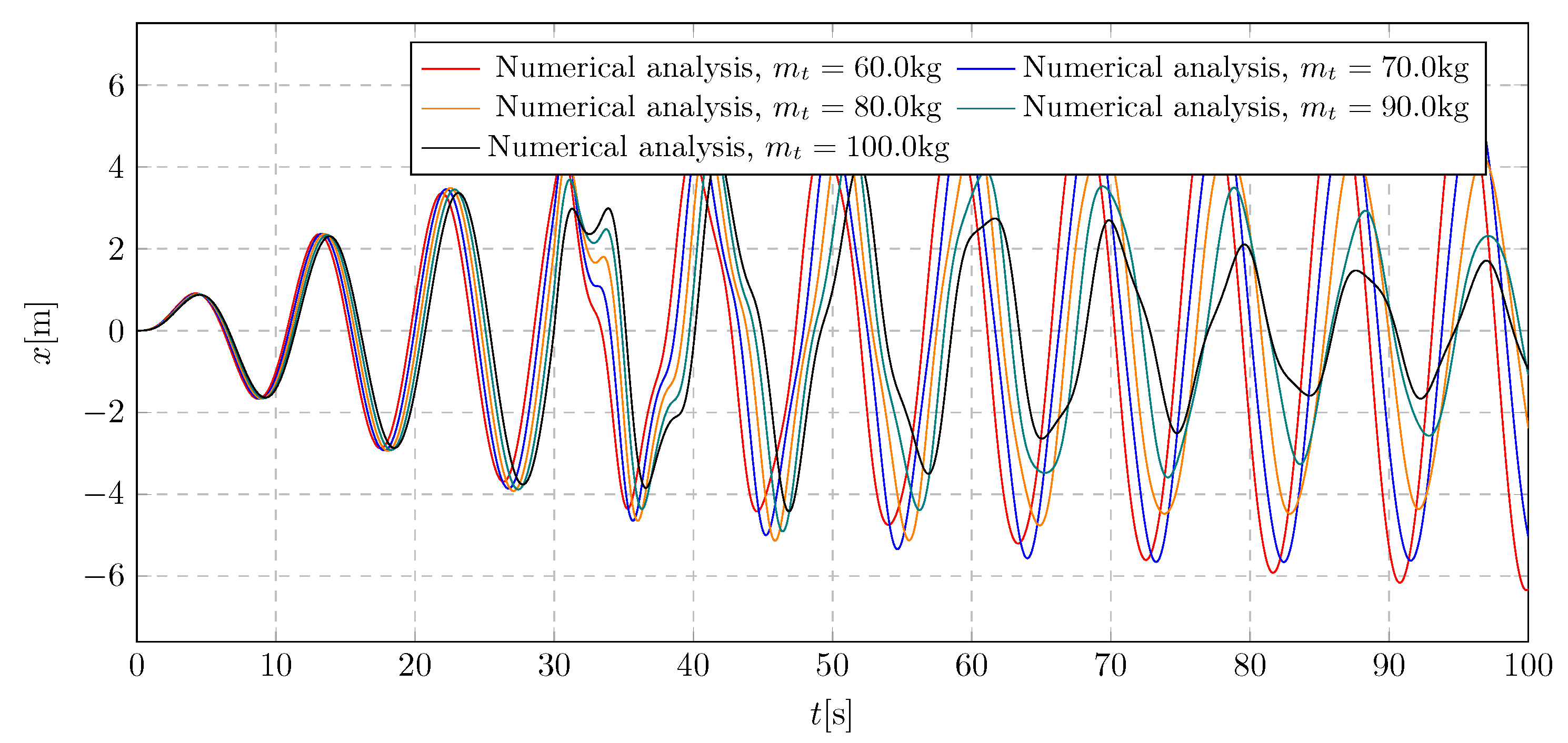
Figure 18.
Frequency spectra of trolley displacement for various trolley initial mass
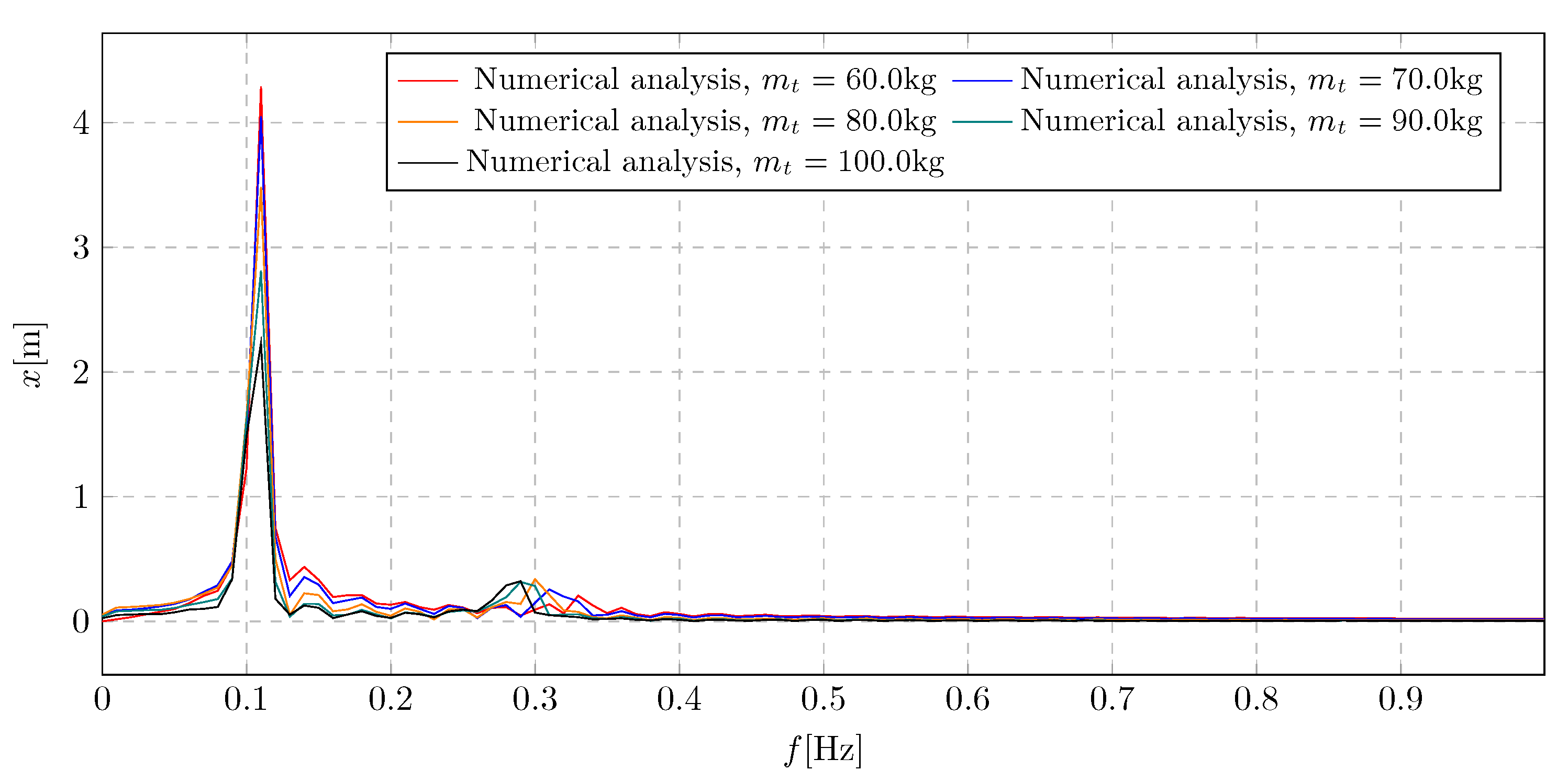
Figure 19.
Pendulum angular displacement for various trolley initial masses
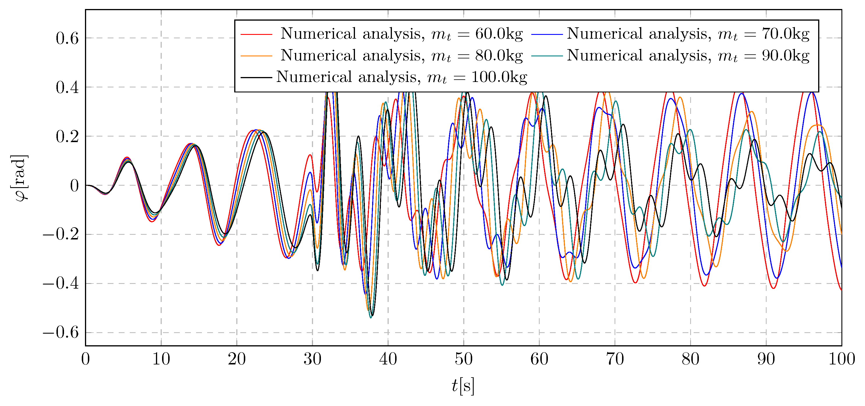
Figure 20.
Frequency spectra of pendulum angular displacement for various initial trolley mass
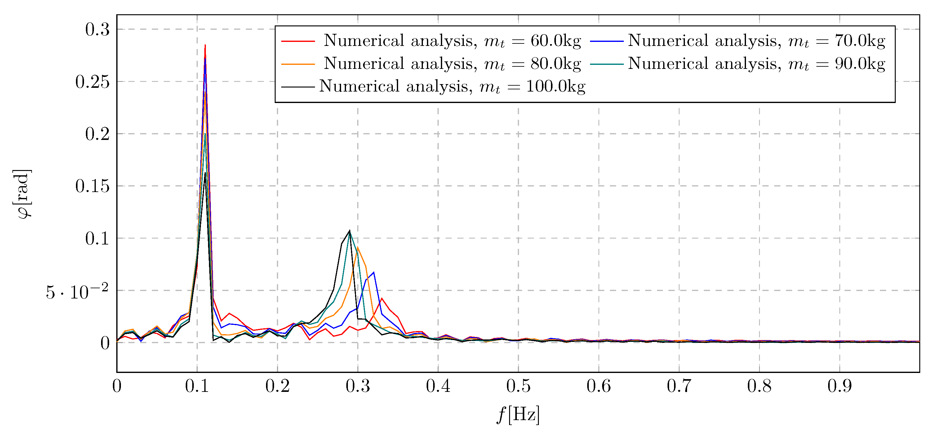
Figure 21.
Trolley displacement for various pendulum initial masses
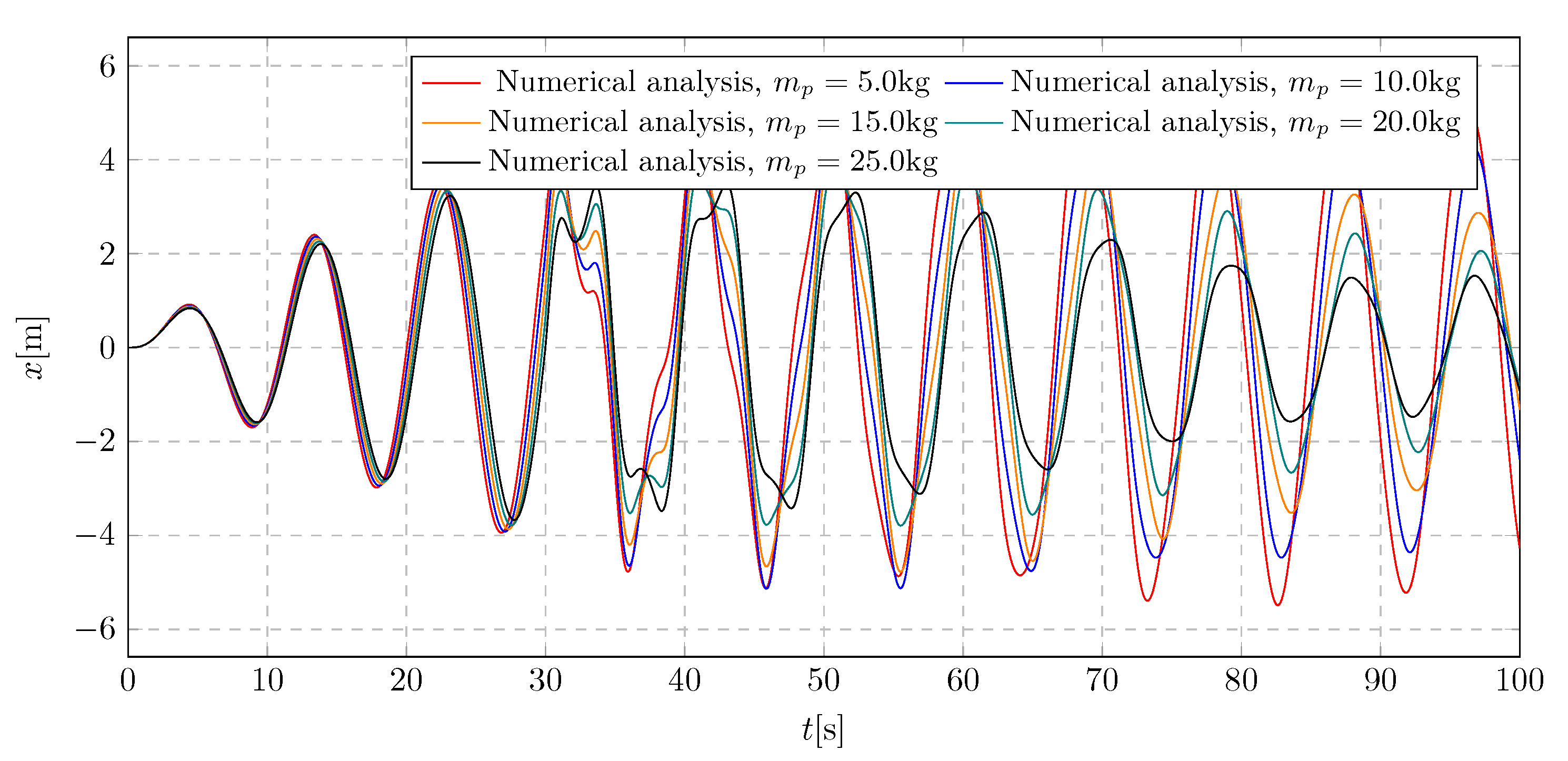
Figure 22.
Frequency spectra of trolley displacement for various pendulum initial mass
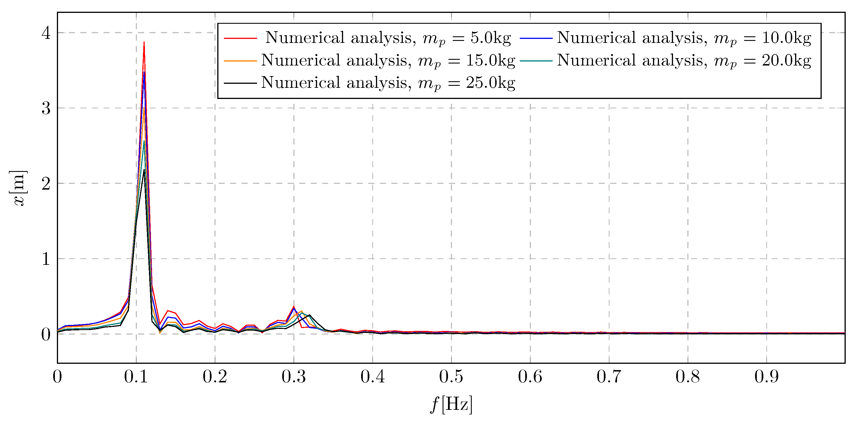
Figure 23.
Pendulum angular displacement for various pendulum initial mass
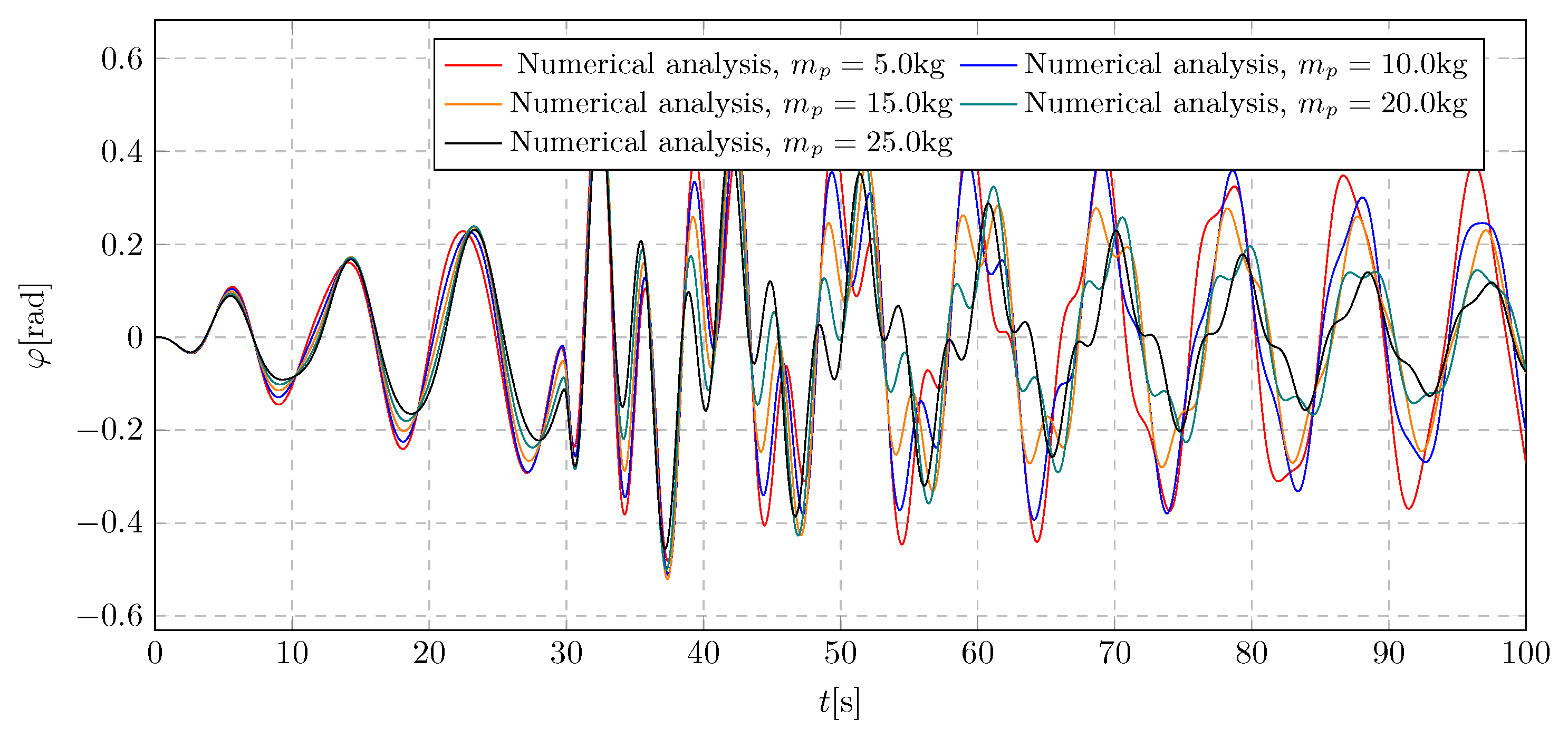
Figure 24.
Frequency spectra of pendulum angular displacement for various pendulum initial mass
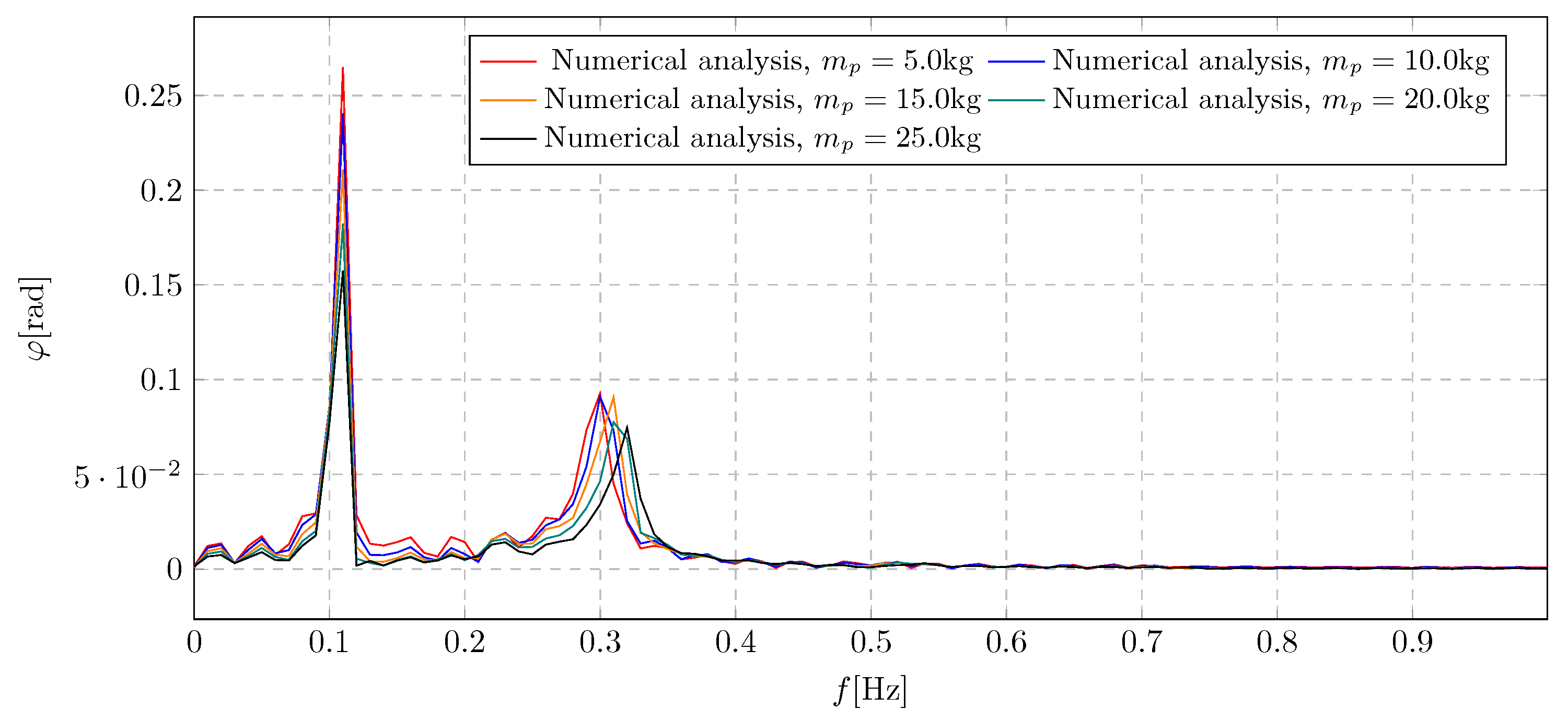
Figure 25.
Trolley displacement for various amount of transfered fluid mass
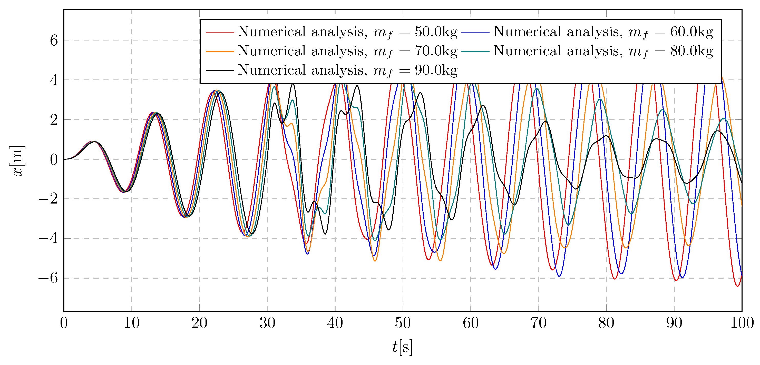
Figure 26.
Frequency spectra of trolley displacement for various amount of transfered fluid mass
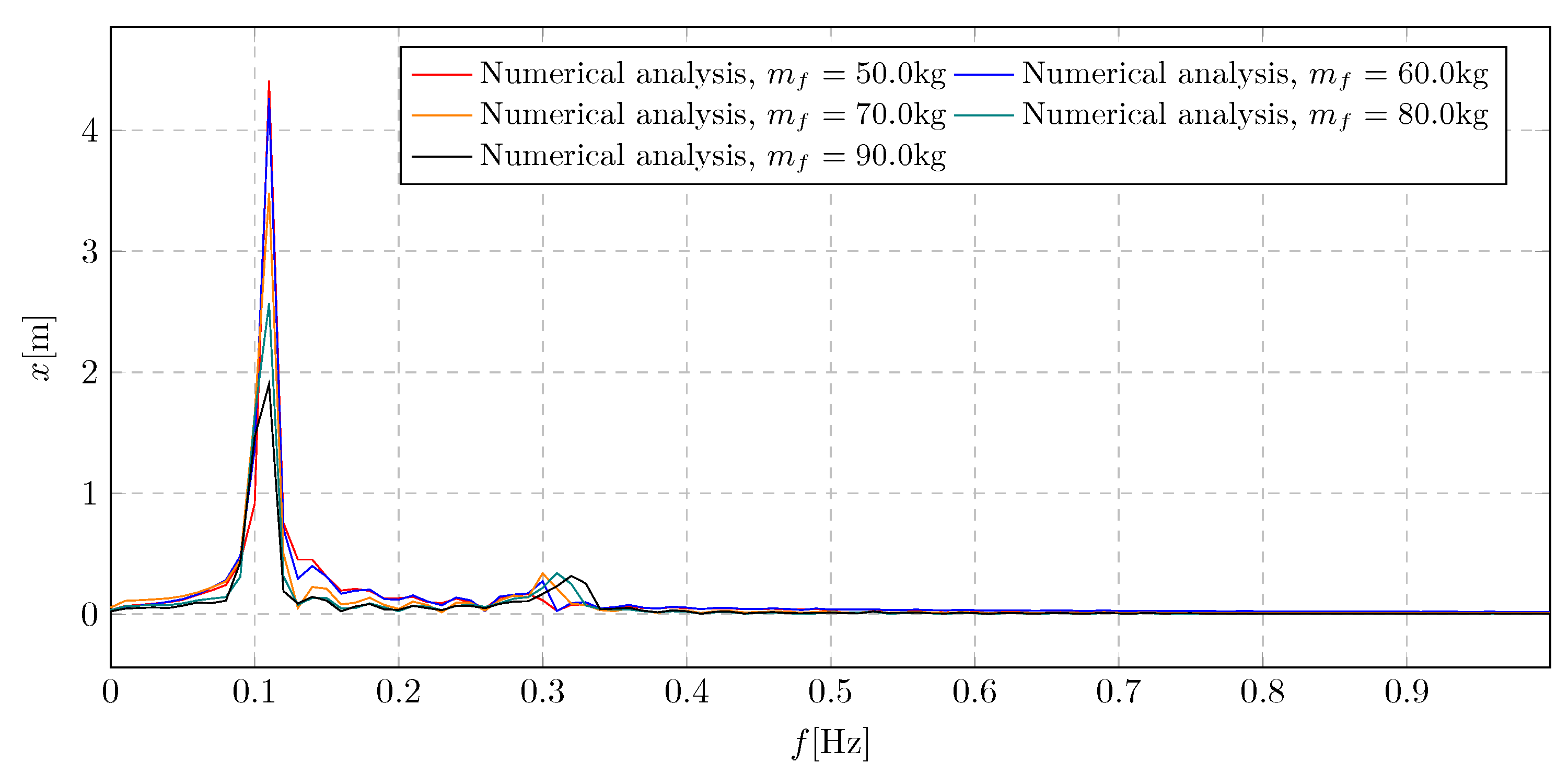
Figure 27.
Pendulum angular displacement for various amount of transfered fluid mass
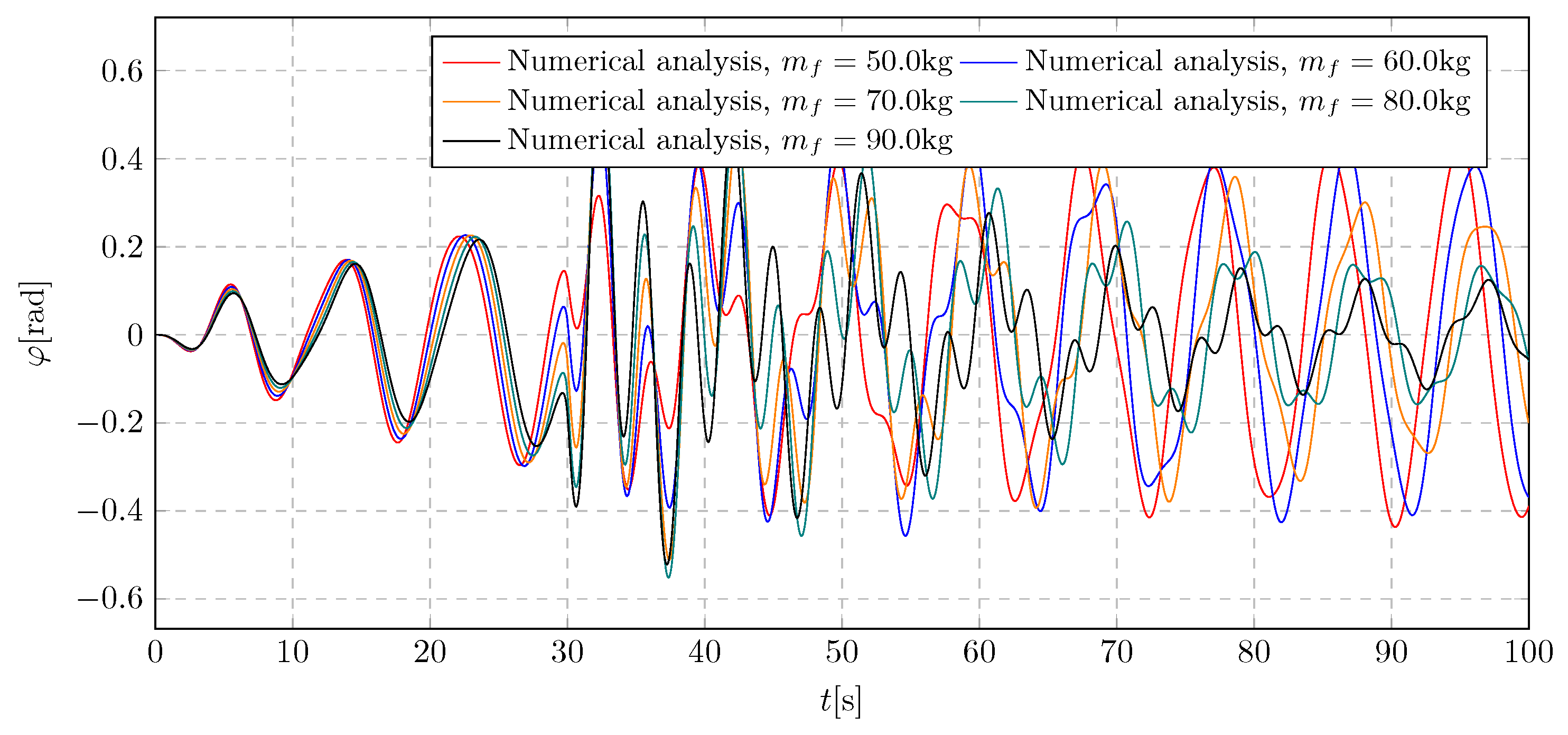
Figure 28.
Frequency spectra of pendulum angular displacement for various amount of transferred fluid mass
Figure 28.
Frequency spectra of pendulum angular displacement for various amount of transferred fluid mass
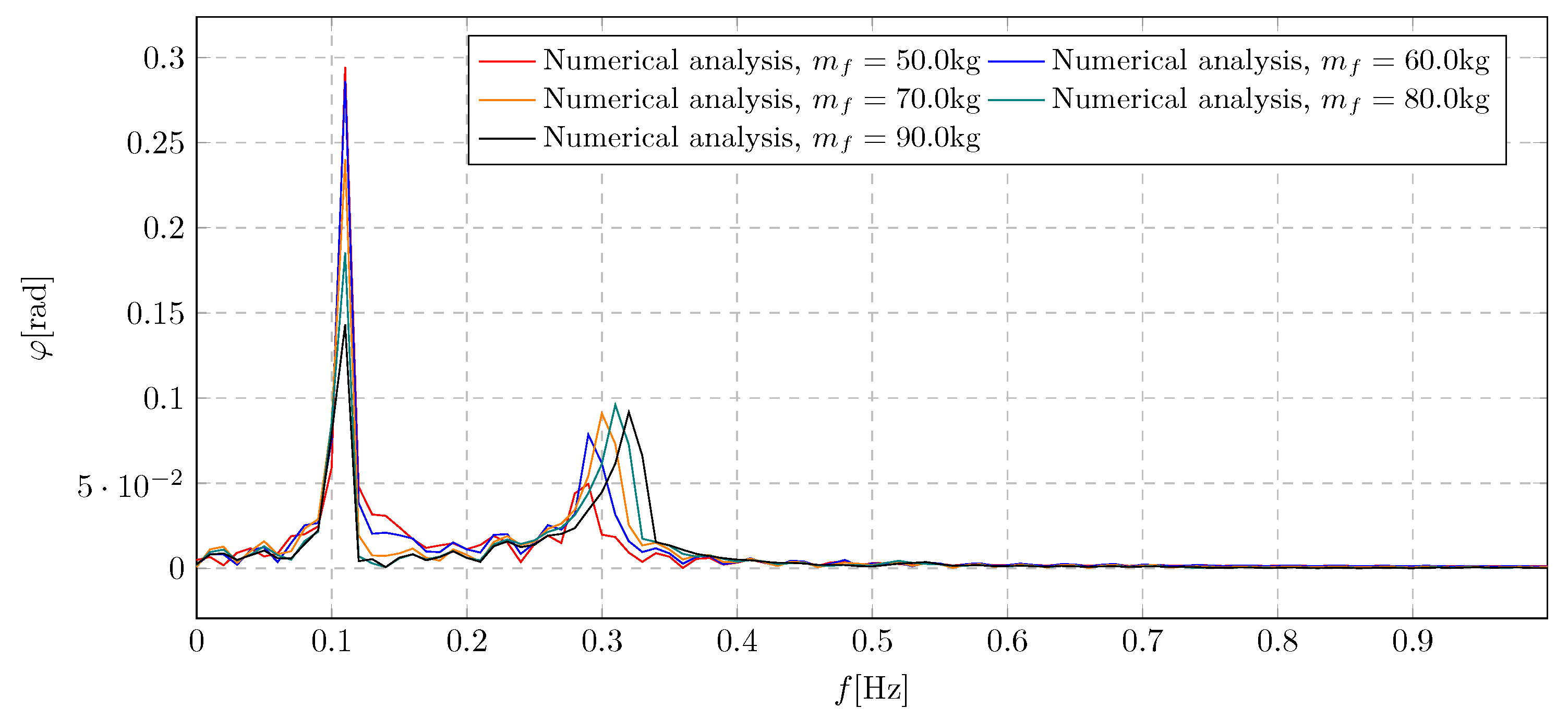
Figure 29.
System validation graph - trolley linear displacement
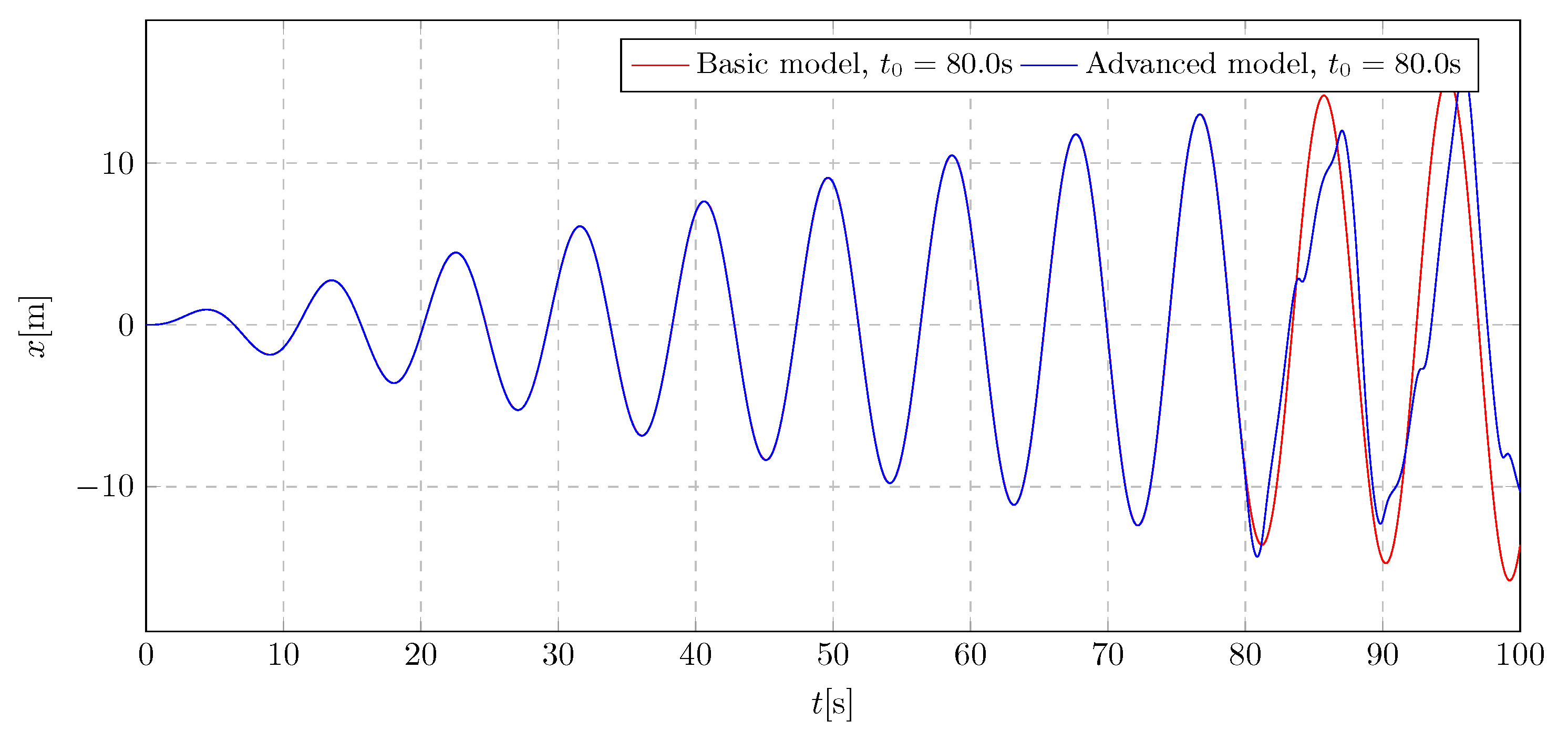
Figure 30.
System validation graph - pendulum angular displacement
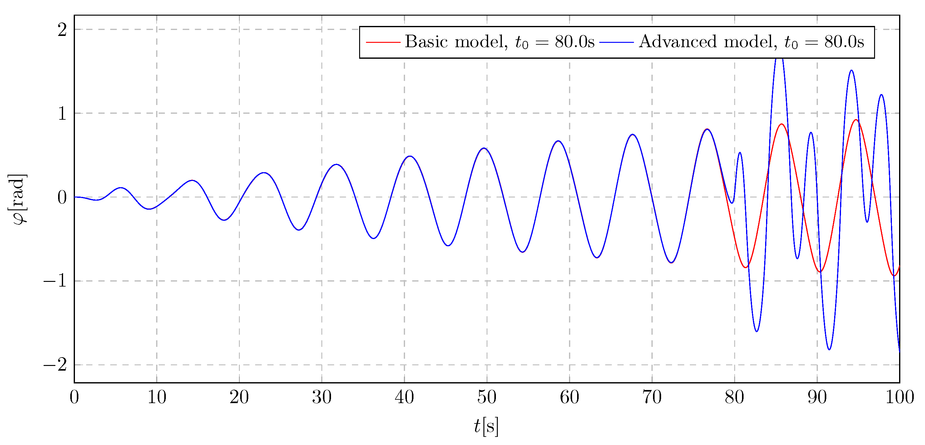
Figure 31.
Block diagram of the test stand and the DAQ system
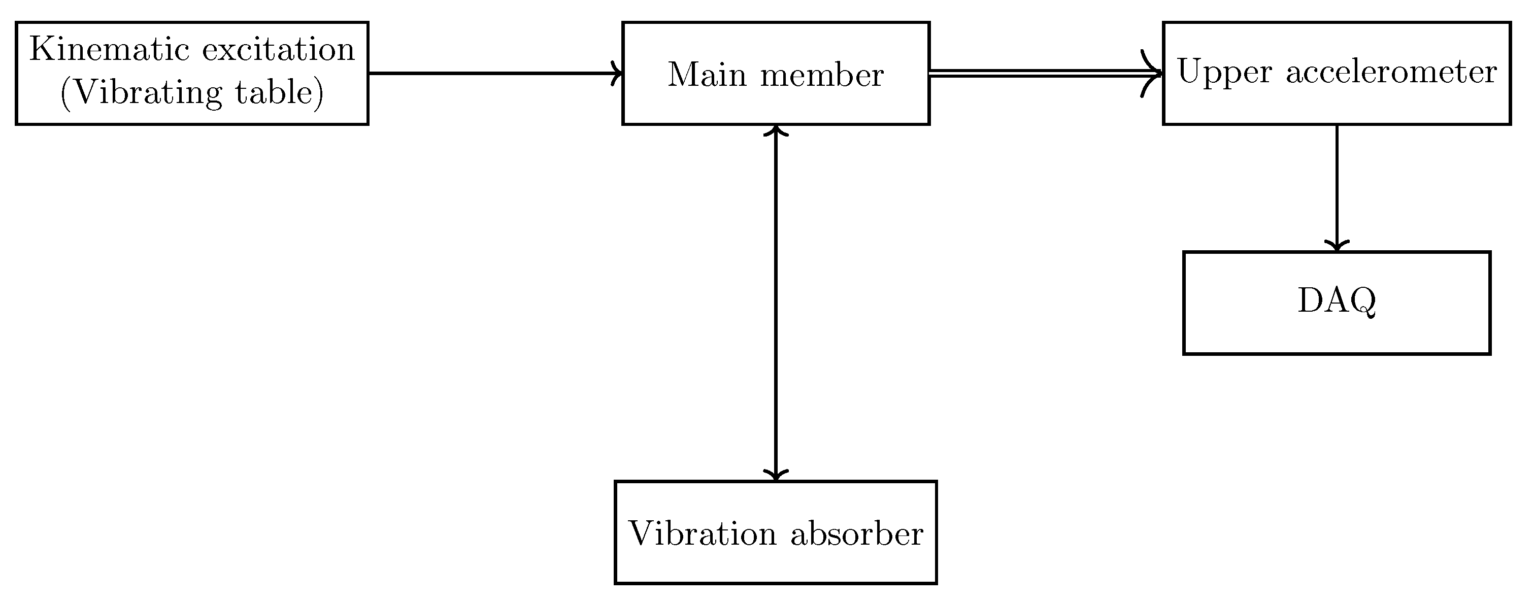
Figure 32.
Test stand based on oscillatory motion
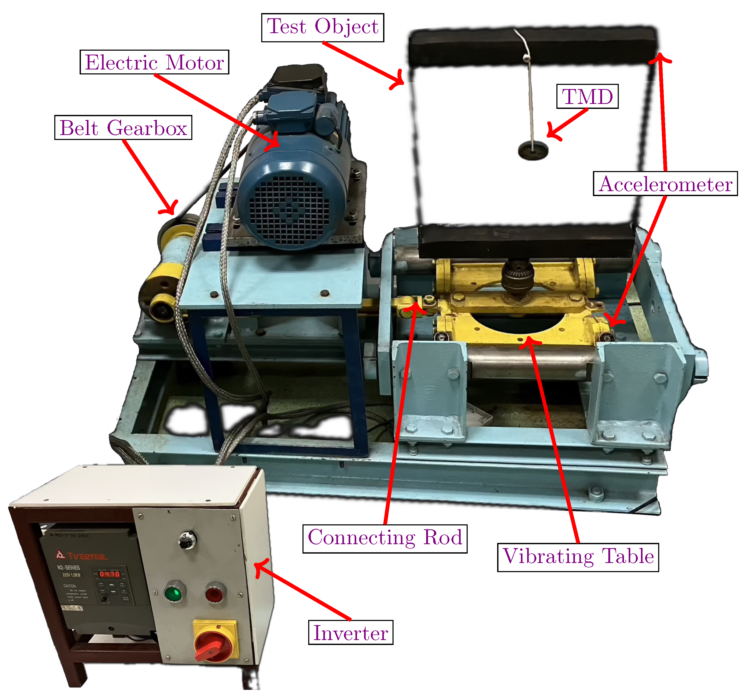
Figure 33.
Data acquisition system components
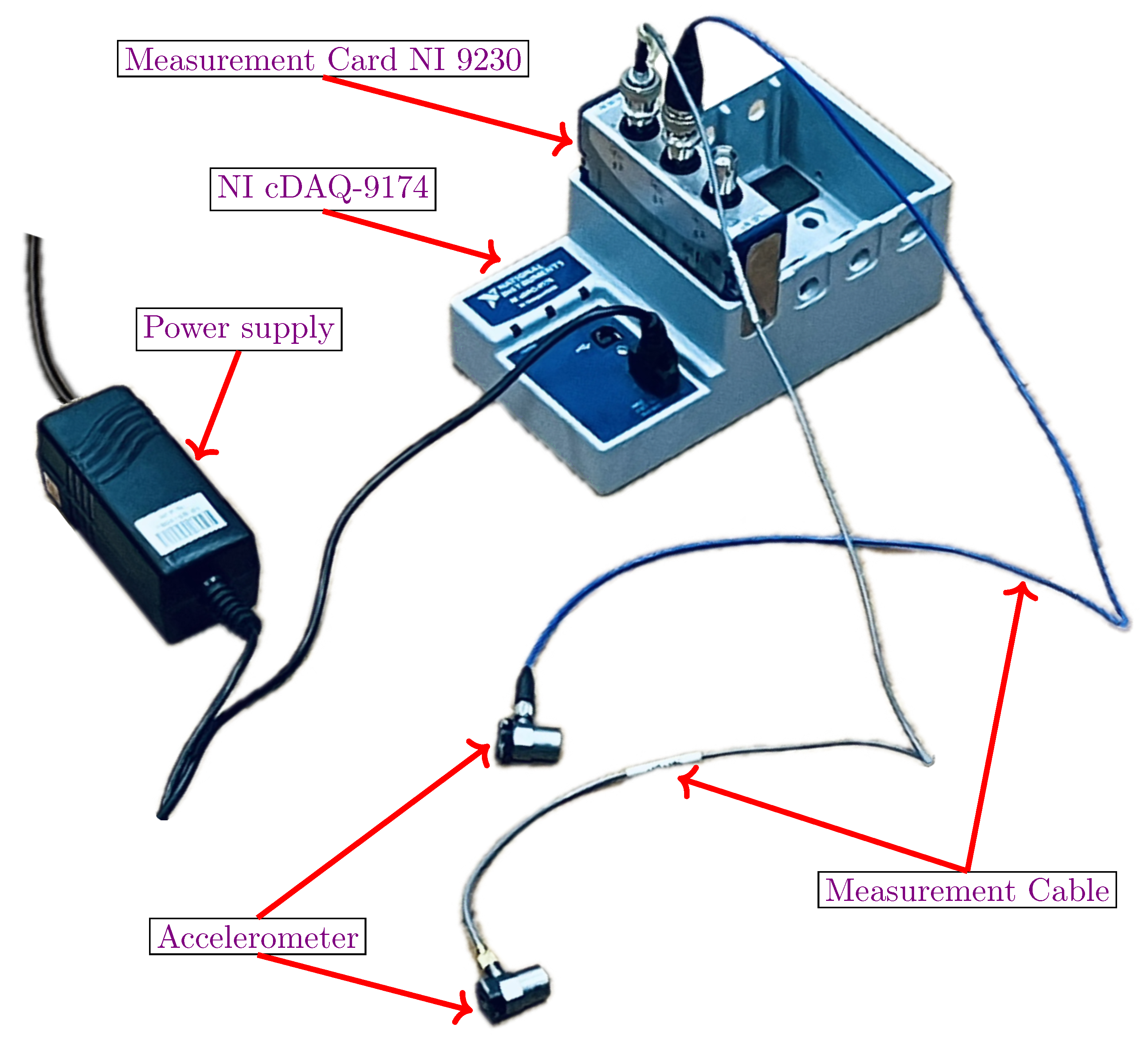
Figure 34.
Data acquisition: NI cDAQ-9174 & NI 9230
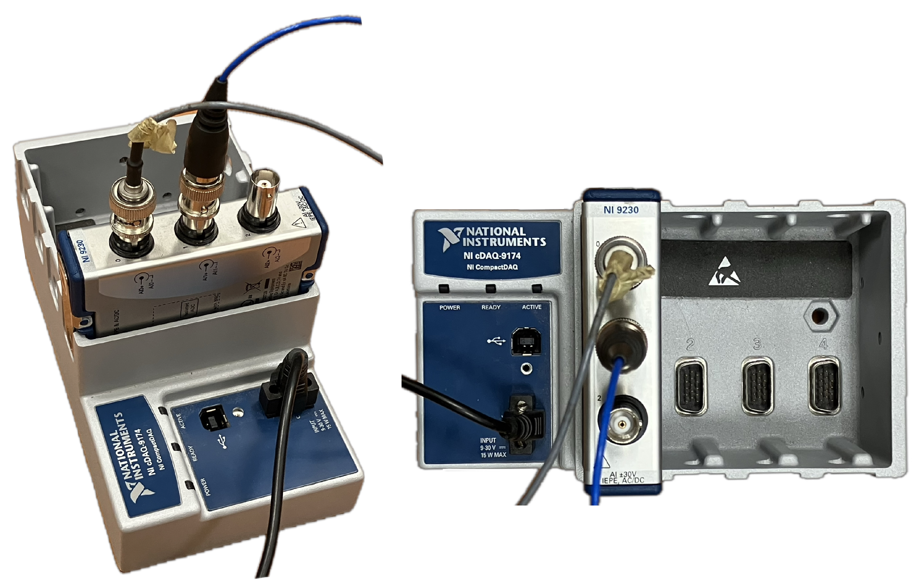
Figure 35.
Without pendulum, initial displacement 5 cm
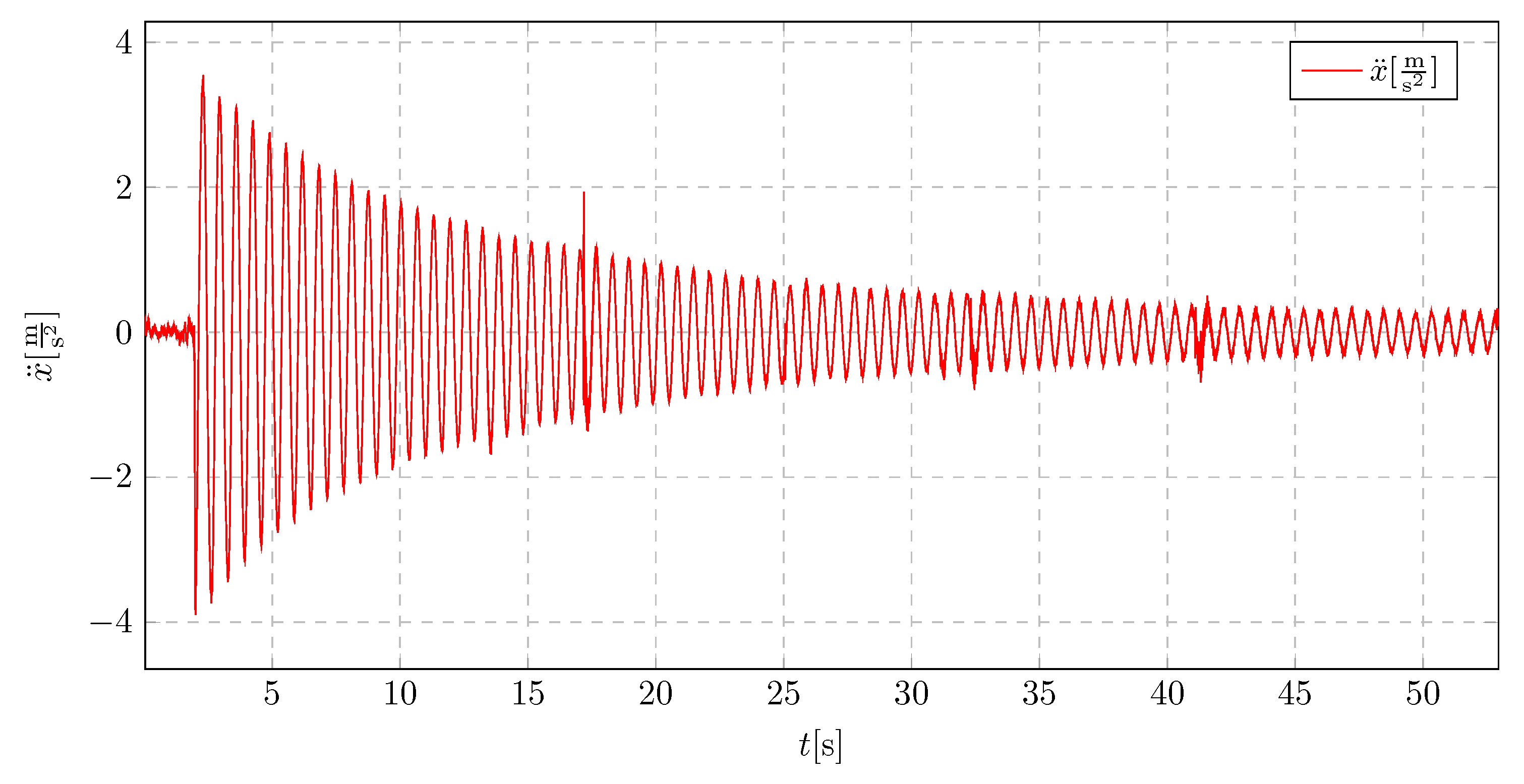
Figure 36.
Pendulum length 25 cm, initial displacement 8 cm
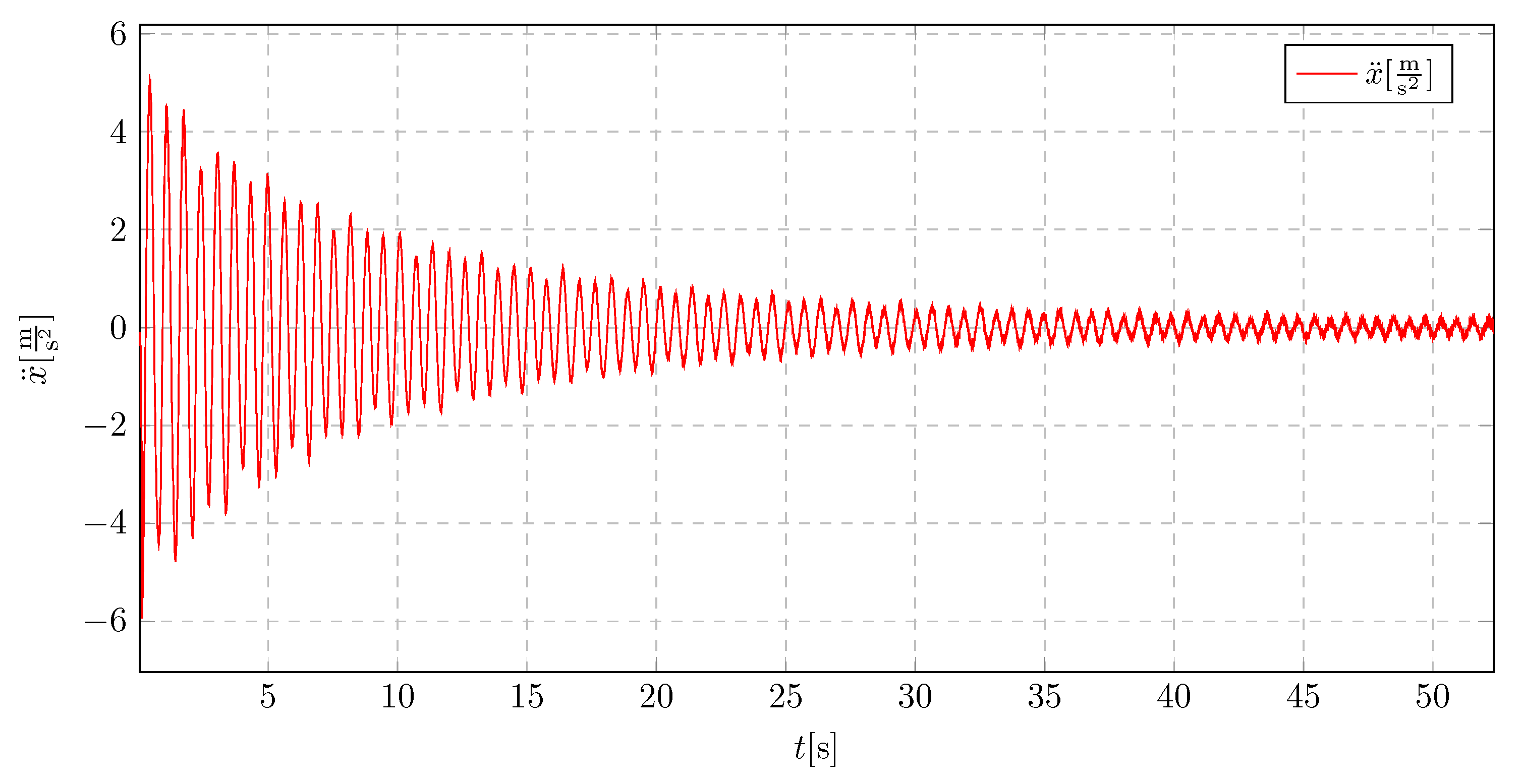
Figure 37.
Pendulum length 25 cm, initial displacement 5 cm
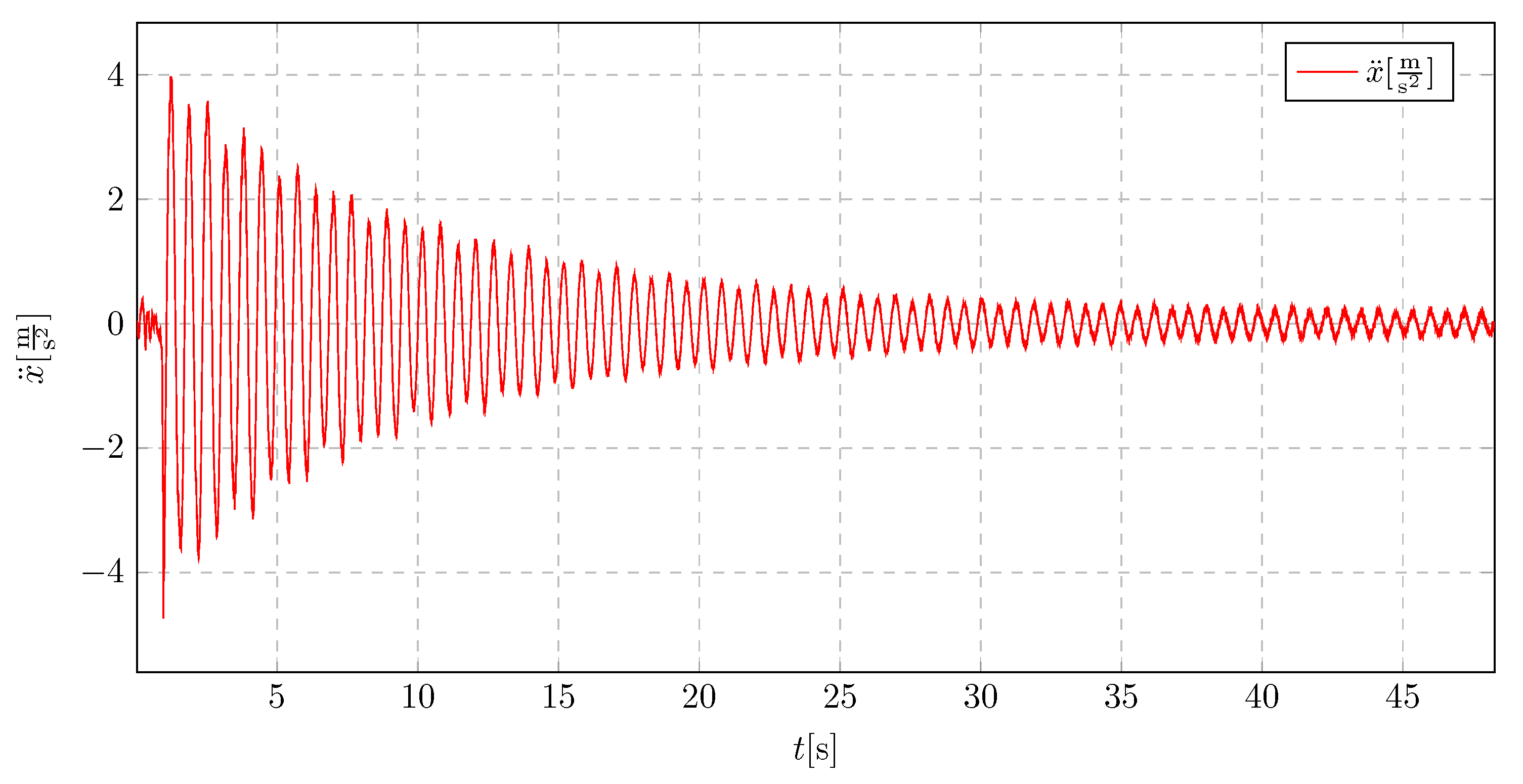
Figure 38.
Pendulum length 15 cm, initial displacement 8 cm
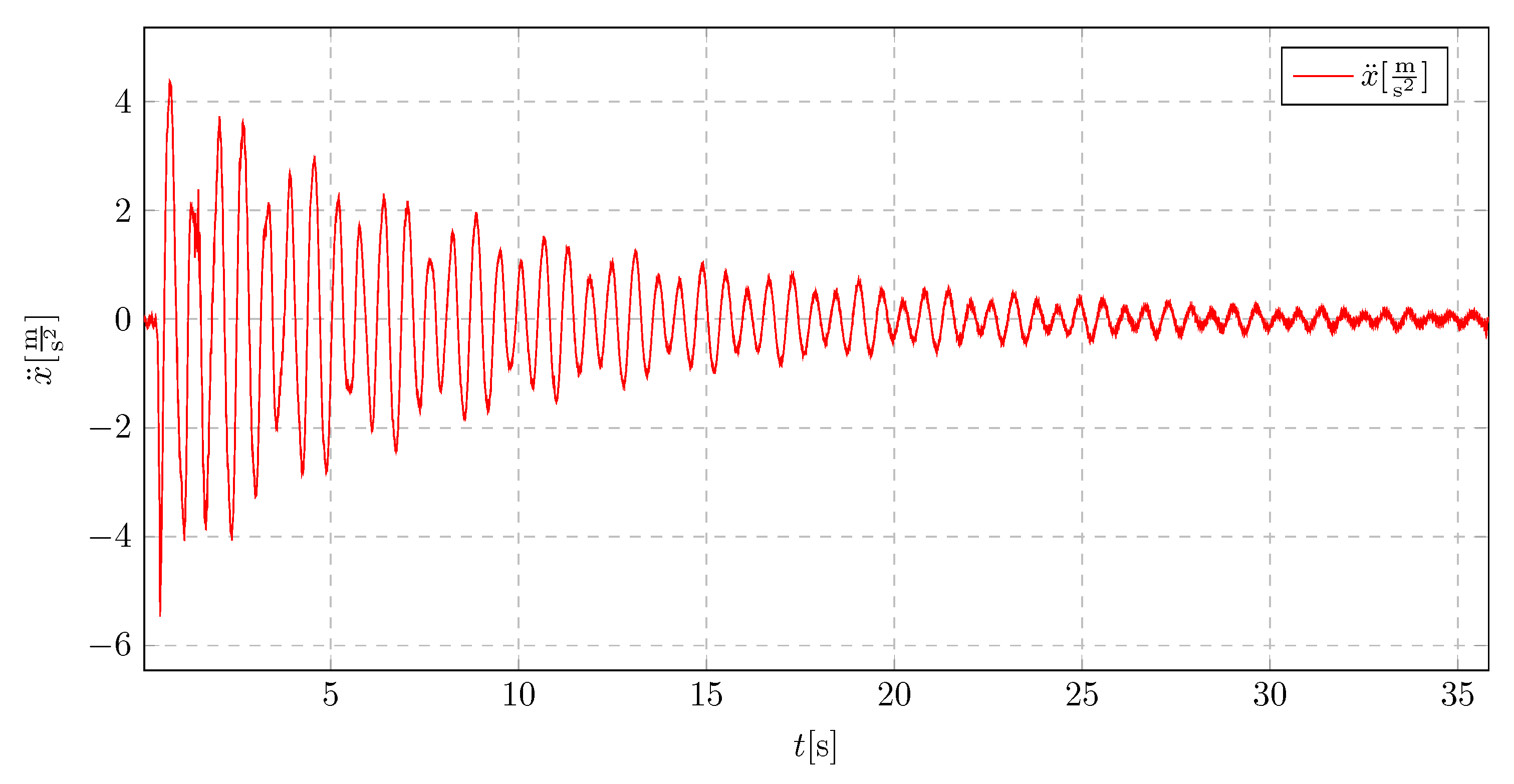
Figure 39.
Pendulum length 15 cm, initial displacement 5 cm
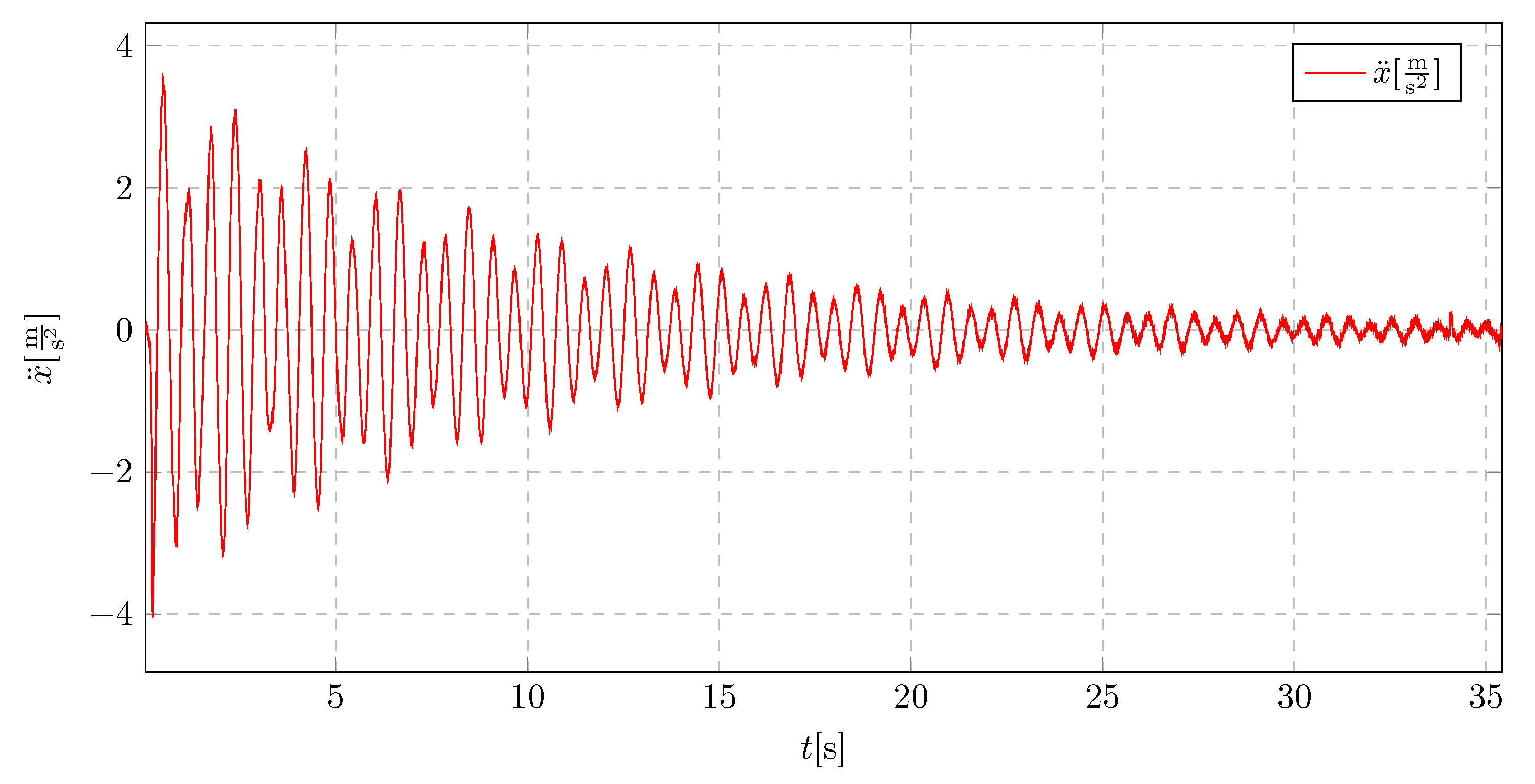
Figure 40.
Pendulum length 10 cm, initial displacement 5 cm
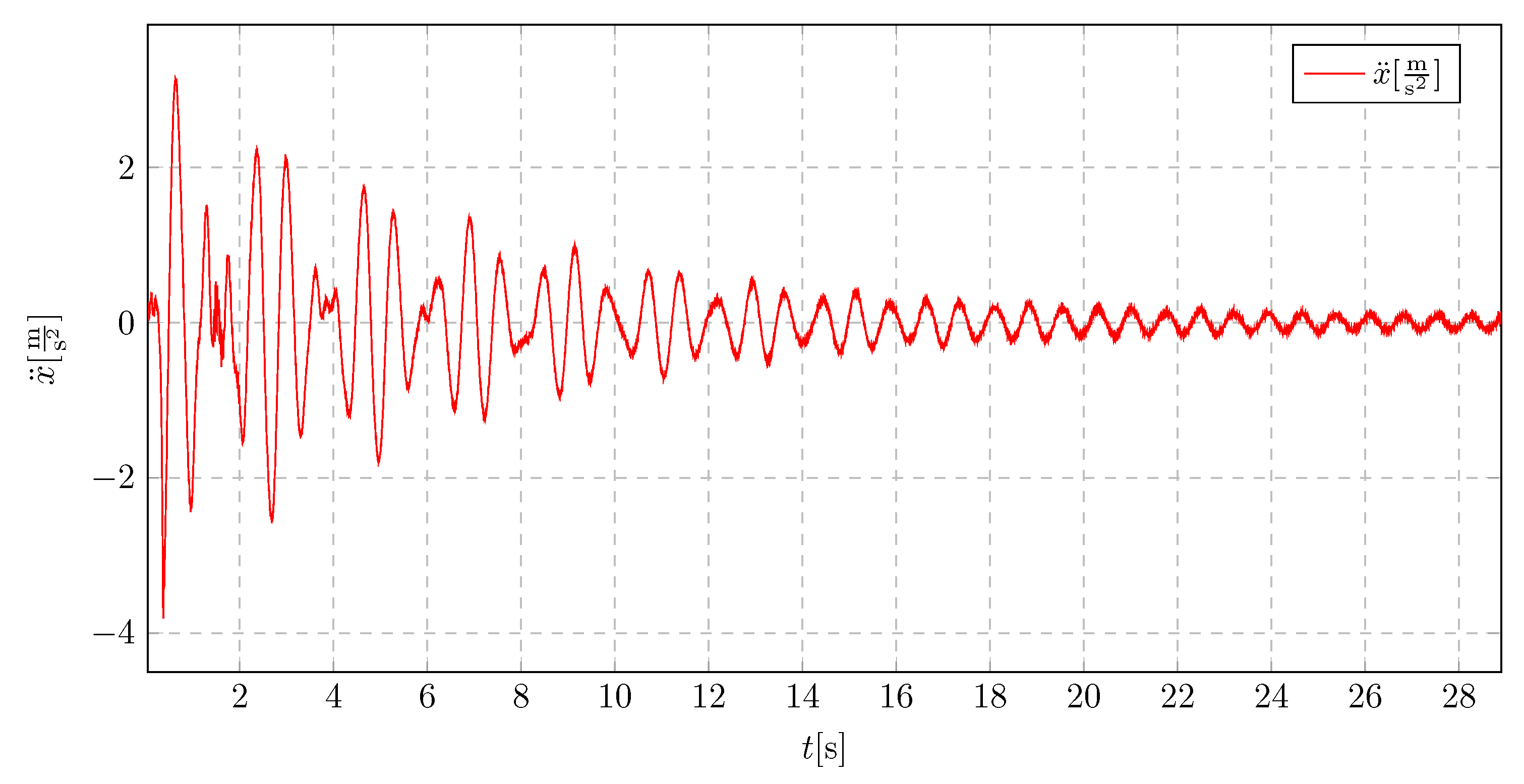
Figure 41.
Pendulum length 9 cm, initial displacement 7 cm
Disclaimer/Publisher’s Note: The statements, opinions and data contained in all publications are solely those of the individual author(s) and contributor(s) and not of MDPI and/or the editor(s). MDPI and/or the editor(s) disclaim responsibility for any injury to people or property resulting from any ideas, methods, instructions or products referred to in the content. |
© 2025 by the authors. Licensee MDPI, Basel, Switzerland. This article is an open access article distributed under the terms and conditions of the Creative Commons Attribution (CC BY) license (http://creativecommons.org/licenses/by/4.0/).
Copyright: This open access article is published under a Creative Commons CC BY 4.0 license, which permit the free download, distribution, and reuse, provided that the author and preprint are cited in any reuse.


