
Submitted:
21 May 2025
Posted:
21 May 2025
You are already at the latest version
Abstract
As real-time embedded systems are becoming ubiquitous, thanks to their sheer inclusion in all kinds of low-cost consumer appliances and the emergence of Internet of Things (IoT) devices, the pressure to enhance firmware development effectiveness and reduce time to market is rising. At the same time, there is a drive towards higher-level programming paradigms, to improve software quality with respect to traditional techniques. This paper presents a framework that enables programmers to deploy typical embedded real-time firmware more conveniently than using plain C-language programming, by abstracting away from tedious, low-level details, such as I/O configuration and operations, as well as the ad-hoc management of multiple, diverse network technologies. Moreover, unlike other proposals, the framework is able to accommodate both time and event-driven applications. Experimental results presented in the paper corroborated the viability, convenience, and better expressiveness of the framework with respect to plain C. At the same time, due to its focus on compile-time versus runtime processing, the framework also exhibited a small execution time overhead and memory footprint, thus confirming its suitability even for microcontrollers with little processing power, like the ones typically found in inexpensive embedded and IoT systems.
Keywords:
Embedded systems
; Logic controllers
; Firmware development frameworks
1. Motivation and Related Work
Most consumer products, including relatively inexpensive ones like kitchen appliances [1], contain at least one embedded processor that engages in some real-time activities. Moreover, those processors evolved from having no networking capabilities at all to a wide range of wired and wireless connectivity options, characterized by a very small hardware cost. In the past decade, this led to the creation of smart devices and smart homes [2,3] and, more generally, a widespread diffusion of the Internet-of-Things (IoT) concept [4,5] that still continues unabated today, especially for application with real-time execution requirements [6,7].
As a consequence, the challenge has become to develop embedded firmware more efficiently than in the past [8], further reducing its production cost and time to market without sacrificing quality. One possible course of action is to move towards a higher-level design method, for instance, Model-Based Design (MBD). MBD has been used successfully in multiple application domains, ranging from data bases [9] to firmware for electricity distribution grids [10], and offers unquestionable advantages, especially for large and mid-size systems with strong reliability and software certification requirements. However, it also forces embedded programmers to embrace a new design and programming paradigm, and become familiar with new languages and tools.
In some cases, especially for C-language programmers, the associated learning curve can be quite steep, like in the case of synchronous languages [11], even in their most recent evolution [12]. Similarly, approaches like the one discussed in [13,14] entail the adoption of an event-driven design paradigm and UML statecharts.
In the case of the CPAL language [15], language design aims at finding the best possible trade-off between staying as close as possible to the C language [16] (which most embedded programmers are likely to be proficient in), while incorporating all the features needed to model, simulate, and program embedded systems, as well as thoroughly scrutinize their behavior. This approach makes the language very versatile and has enabled its application to multiple case studies, like communication protocol analysis [17], fault tolerance [18] and, more recently, the verification of an aerial video tracking system [19]. Nevertheless, programmers are still required to learn the CPAL language anew, as well as its specific tools and development environment.
Programming environments for Programmable Logic Controllers (PLCs) [20], either proprietary [21] or open-source [22], are also very powerful, especially when confronted with typical industrial automation applications. They are undoubtedly popular [23,24] but, like the previously mentioned ones, they are also tightly associated with dedicated Domain-Specific Languages (DSLs), such as the ones defined in [25], and the cost of PLC hardware is typically much higher than the cost of a microcontroller-based board of comparable processing power.
Arduino-based systems [26] have their own software development framework that adopts a simplified dialect of the C++ language, but the programming model consists of a single main loop that contains the code to be executed. As a consequence, along the years it has been extended in various non-native ways to suitably support multitasking, in either a cooperative [27] or preemptive [28,29] way, since such a feature becomes mandatory as the complexity of real-time embedded applications grows. A downside of cooperative approaches is that task execution is indeed cooperative. Hence, task switches are under the control of the running task and are executed timely only if tasks have been implemented correctly. At the same time, preemptive approaches make the underlying programming model more complex and introduce a new set of potential pitfalls, like race conditions, which Arduino programmers may or may not be aware of.
Other proposals, like the one described in [30,31] succeeded in speeding up firmware development by leveraging a variety of sophisticated, open-source firmware components, such as real-time operating systems (RTOS) [32], filesystems [33], and TCP/IP protocol stacks [34]. Besides being quite sophisticated, those components have the additional advantage of being portable, and hence, readily available on many embedded platforms. However, even though those proposals effectively support modular embedded system construction and allow programmers to use the C language, they still lack much needed abstraction. As an example, if a programmer wants to read a process variable available on a sensor connected to the processor by means of a field bus like the Controller Area Network (CAN) [35] or via Ethernet, he/she still needs to know all the details about this connection and call the appropriate library functions. Even more importantly, the corresponding code needs to be updated whenever the connection method changes as hardware technology evolves.
To address the shortcomings discussed previously, this paper describes a novel firmware development framework called RtFw and loosely based on preliminary work presented in [36]. Its main goal is to build an abstraction layer that shields application-level firmware developers from most low-level architectural details. For instance, RtFw abstracts away from Input–Output (I/O) mechanisms through a flexible configuration system that maps conventional C-language variables into local or remote I/O points. In this way, programmers may still use plain C-language statements to manipulate those variables, while RtFw transports their value to and from I/O points, even across a network, thus reaching a convenient trade-off among the goals previously discussed. Unlike other proposals and differently from [36], the framework is able to handle multiple field buses and network technologies transparently. Even more importantly, it also supports event-driven programming besides the more traditional cyclic, time-driven paradigm, provided sensors, actuators, and the underlying networks implement event-driven messaging. The former has been steadily gaining popularity for its advantages, not least resource efficiency [37]. At the same time, the attention paid to execution efficiency during design and implementation makes RtFw suitable even for very low-cost microcontrollers.
The paper is organized as follows: Section 2 outlines the architecture and the main building blocks of RtFw, while Section 3 provides more details about its main components, also focusing on implementation-related aspects. Section 4 provides information on how the event-driven paradigm fits in the framework, Section 5 focuses on system configuration, and Section 6 highlights how RtFw supports Internet-based access to the embedded system. Finally, Section 7 presents and analyzes experimental data concerning performance, overhead, and memory footprint. Section 8 concludes the paper.
2. System Architecture
Figure 1 depicts the typical system architecture an RtFw system is built upon. As shown in the figure, the main controller card hosts a microprocessor-based real-time embedded system, possibly connected to some local devices through an on-chip or on-board bus. Given that embedded systems design has been shifting from a centralized towards a distributed I/O paradigm [38], RtFw also supports remote I/O cards, which the control system can reach via a serial RS-485 multidrop line, a CAN [35] bus or an Ethernet network. CAN-based communication may be based on the Modbus-CAN protocol [39] or CANopen [40], while Modbus-TCP [41] is suitable for Ethernet. Legacy devices may be handled by means of Modbus-RTU [42] on RS-485. All these protocols are fully supported by multiple, readily available open and closed-source libraries, like [43,44,45].
An additional feature of RtFw, shown in the bottom-right part of the figure, is the ability of granting access to a subset of its internal state to other agents and support Internet access. This feature is extremely important for key functionality—such as data logging, supervision, and firmware upgrades—and has been implemented by means of proxies and the Internet access mechanism discussed in Section 3.3 and Section 6, respectively. Finally, user access is made possible by means of a local or Internet-based user interface (UI). Both share relevant information with the real-time portion of the system.
Internet communication typically takes place through a dedicated, Ethernet-based, best-effort network, as shown in Figure 1. However, on systems with less demanding bandwidth requirements and real-time constraints, physically segregating real-time and best-effort traffic into their own network segment may be unnecessary. Instead, a single Ethernet segment may profitably be used for both, with the assistance of a prioritization mechanism like the 8802-1Q Priority Code Point (PCP) of VLAN-tagged frames [46]. The use of Time Sensitive Networks has been ruled out because their complexity would probably make them unsuitable for the class of embedded systems targeted by RtFw.
As real-time execution model RtFw implements a cyclic executive [47] augmented with a mechanism to react to asynchronous events generated by remote I/O devices, thus making both time-driven and event-driven programming possible. Both will be discussed in more detail in Section 3.1 and Section 4, respectively. Even though more sophisticated execution models have been proposed in the past [48], the cyclic executive has the advantage of being well-adapted to the cyclic, master-slave communication of Modbus [49] and the time-driven Protocol Data Objects (PDO) of CANopen [40]. At the same time, asynchronous event reaction accommodates event-driven CANopen PDOs.
To make RtFw more portable and flexible [50], its execution model has been layered on top of a general task-based system, coordinated by the FreeRTOS open-source RTOS [32]. The underlying RTOS is also useful, for instance, to seamlessly integrate a multi-task UI while keeping it separate from the real-time control system from the logical and timings point of view. Moreover, most of the third-party firmware components used by RtFw and mentioned previously are likely to require, or highly benefit from, the availability of RTOS services and multitasking.
3. Core Framework Components
All core framework components, whose internal structure is shown in Figure 2, reside on the main controller card. Generally speaking, RtFw consists of three main groups of cooperating tasks, which store and exchange information by means of several shared data structures. Two of them, related to time-driven programming, are discussed in Section 3.2 and Section 3.3, while the third supports event-driven programming and is described in detail in Section 4.
A configuration system allows programmers to set up local and remote I/O points and access them through ordinary C-language variables, while RtFw takes care of retrieving input data and deliver output data, either locally or through one of the available real-time networks and buses. In addition, the configuration system determines which portion of real-time state information shall be exported by the real-time firmware. To make configuration files easier to write and reduce the number of additional software tools needed to handle them, their content follows the C-language macro invocation syntax and is processed by the C preprocessor, an omnipresent part of every embedded systems development toolchain.
3.1. Real-time Tasks and Control Cycle
The first group of tasks implements the cyclic executive and consists of a control task and a timer task. Within these tasks, the only user-provided code is a control function, depicted as a gray block in Figure 2. This function is invoked by the RtFw control task cyclically, to execute the time-driven part of the real-time algorithms. In addition, RtFw activates the control task to handle sporadic events generated by other parts of the firmware and execute the event-driven part of the real-time algorithms. Those events mainly arise from a sporadic event notification message coming from one of the real-time networks, represented by data flow ⑪ in the figure, an event-driven UI, or a proxy, represented by ➆. Also in this case, the control task delegates event handling to the control function. One of the control function arguments enables it to distinguish whether it was called due to a cyclic or a sporadic event and act accordingly. In addition, the framework itself may generate sporadic events to inform the control function about various error conditions.
The timer task consists entirely of RtFw code. It makes use of a suitable RTOS timing primitive, vTaskDelayUntil in the case of FreeRTOS, to schedule its execution every control cycle period. This periodic schedule is then used to generate a stream of events that drives cyclic execution. The stream is conveyed to an event system through data flow ➇. The event system is responsible for collecting cyclic, as well as sporadic events, and deliver them to the control task by activating it whenever an event occurs. As explained previously, real-time networks, UI, and proxy tasks can notify the event system about the occurrence of a sporadic event as well, by means of data flows ⑪ and ➆, respectively.
The event system consists of a FreeRTOS message queue Q of N elements and a counting semaphore R. The main goal of Q is to buffer up to one cyclic event and sporadic events. The actual values stored in the queue are integer event identifiers, useful to distinguish cyclic from sporadic events and, at a finer granularity, one class of events from another.
Considering that cyclic events must be given higher priority than sporadic events to bound control cycle jitter, cyclic events are always inserted at the front of Q. Instead, sporadic events are appended to its back, to be processed in a first-in, first-out (FIFO) fashion. This is consistent with the message queue primitives xQueueSendToFront and xQueueSendToBack that FreeRTOS provides, and is well within the capabilities of any other RTOS.
By itself, prioritizing the way events are enqueued is insufficient to grant cyclic events expedited handling, unless there is a way to guarantee that Q is never completely full when a cyclic event occurs. Otherwise, any enqueue operation—no matter it is directed to the front or the back of the queue—would block the caller. RtFw addresses this potential issue by ensuring that Q never contains more than sporadic events, under the assumption that no cyclic events are ever generated while another cyclic event is still in the queue.
The counting semaphore R is used exactly for this purpose. More specifically, it keeps record of free elements in Q that are available for sporadic events at the moment, and blocks sporadic event sources as needed, to exert back pressure on them. Accordingly, sporadic event insertions are preceded by a potentially blocking xSemaphoreTake operation on R and sporadic event extractions are followed by a matching xSemaphoreGive. The assumption mentioned previously is reasonable because violating it would imply there was a cycle overflow, which is considered a severe error condition in a cyclic executive [47]. As a simple form of recovery, RtFw skips a control cycle whenever it detects a cycle overflow, keeping track of the occurrence in its status and diagnostic information.
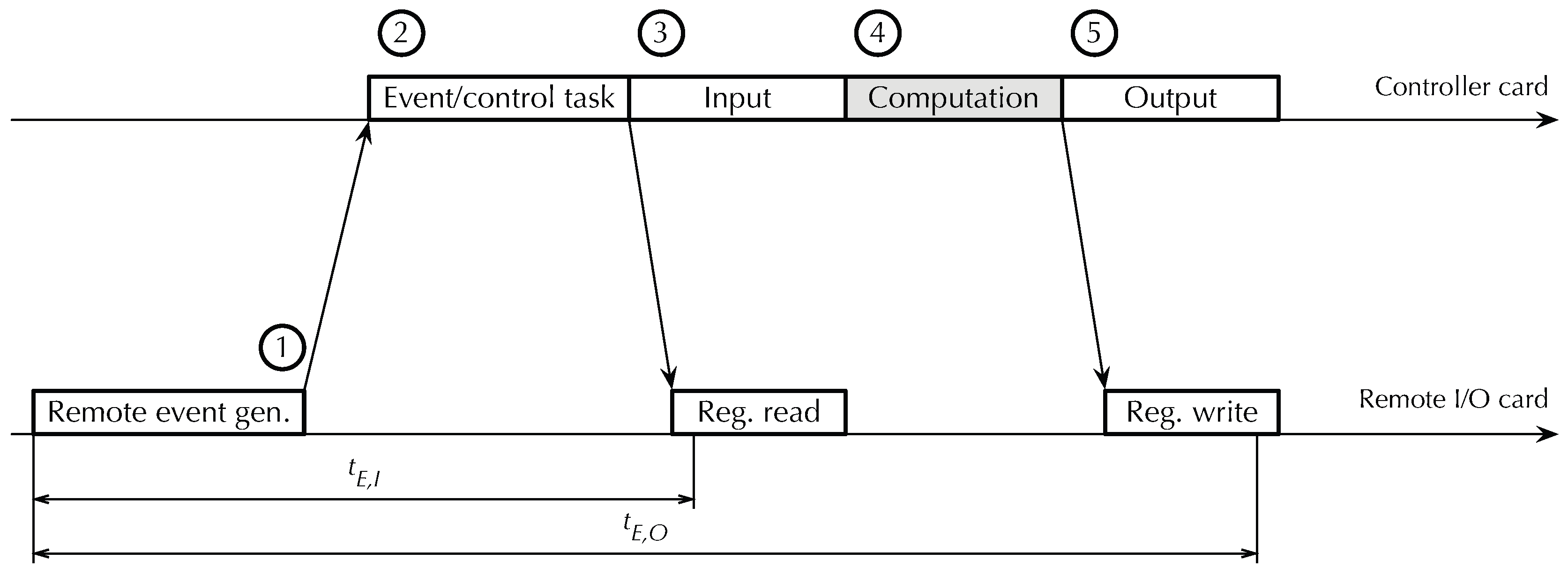
The control task activates whenever there is an incoming event by waiting to receive a message from Q through data flow ➈. Upon receiving a cyclic event, it implements most of the control cycle, except for the control algorithm, which the control function is still responsible for. Figure 3 shows the structure of the control cycle in more detail. Each cycle consists of three mandatory phases, followed by one optional phase:
- 1.
- During the computation phase (C phase) the control task executes the time-triggered portion of the real-time algorithms, by invoking the control function. The control function operates on input data and stores results into output data held in abstract process image (PI) variables through bi-directional data flow ➁ shown in Figure 2. These variables are stored in their own memory area, denoted as [A] in the figure, and are mapped to local or remote I/O points by the system configuration to be discussed in Section 5.
- 2.
- In the output phase (O phase) the control task commits the value of all output PI variables to the corresponding output points, possibly going through a data format conversion stage specified by the configuration system. The conversion is transparent to the control function and adapts the CPU-dependent representation of memory-resident data to the format required by each specific I/O device. All I/O activities are performed by a real-time communication module, assisted by a set of real-time I/O libraries that provide I/O functions specific to each communication medium RtFw supports.
- 3.
- Finally, in the input phase (I phase) the control task queries input points and stores their values into the corresponding input PI variables, ready to be used during the C phase of the next cycle. Also in this case, data format conversions are performed as required and I/O activities are coordinated by the communication module. During both the O and I phases, input and output data are transferred through data flow ➀ and the control function is kept inactive to avoid race conditions.
Figure 3.
Real-time control cycle and sporadic event handling.
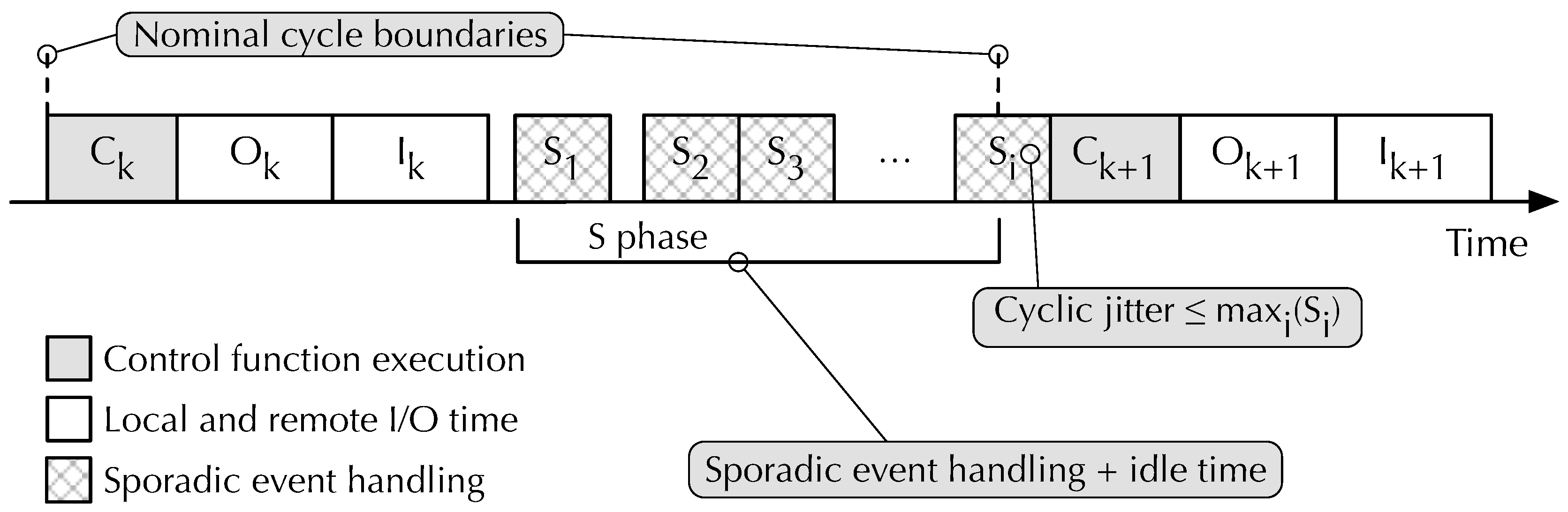
After completing these three phases, the control task starts the S phase, in which it checks whether there are sporadic events waiting in the queue. If there is none, the control task remains idle until a sporadic event arrives or the next cycle is due to begin, as signaled by the arrival of a new cyclic event. If some sporadic events are pending, the control task dispatches them, one at a time, to the control function. Therefore, as also shown in Figure 3, the S phase is composed of zero or more sporadic event handling intervals interleaved with idle time.
Although the handling of further sporadic events stops as soon as a cyclic event is inserted into Q—thanks to the prioritization mechanism discussed previously—the processing of the current sporadic event is allowed to complete before starting the next cycle. This event serialization approach simplifies synchronization within the control task and control function—because, in fact, there is no internal concurrency. However, it may introduce jitter at control cycle boundaries. Namely, the processing of the last sporadic event in the S phase of cycle k may delay the beginning of cycle . However, the amount of jitter is upper-bounded and, denoting the processing time of sporadic event i as , the upper bound is , regardless of the number of sporadic events in Q.
For sporadic events generated by UI and proxy tasks the internal structure of the corresponding consists only of activities internal to the controller card performed by the control function. On the contrary, the handling of events coming from a real-time network involves I/O operations to properly refresh PI variables. They are performed by the control task, transparently and independently of the control function, as described in Section 4.
3.2. Control Function
The user-written control function, depicted as a gray block in Figure 2, is responsible of implementing the C phase of the cyclic executive, as well as handling all sporadic events generated by other parts of the firmware. As such, RtFw invokes it with four arguments:
- A pointer to the RtFw state. Although simple time-triggered control functions may let RtFw manage it automatically, more complex control functions can query it to get detailed runtime information about all RtFw components. Moreover, during sporadic event handling the control function must inform RtFw of any updates it made to PI variables, so that the control task can refresh them appropriately.
- The current cycle number, which gives the control function information about elapsed time with a granularity of the cyclic executive period. Since this data item has limited width (32 bits in the current implementation), RtFw provides functions for modulo- time calculations. In order to support more sophisticated time-driven execution patterns, RtFw also provides multiple one-shot and periodic timers that the control function can set at will, with the same resolution. Higher-resolution timers for event-driven programming are made available by the underlying operating system and utility libraries.
- The event type that triggered the current invocation. The first and most important information that the control function can derive from this argument is whether it should perform a time-triggered C phase or handle a sporadic event. In the second case, it conveys more information about the event itself.
- A pointer to a user-defined data structure, which the user communicates to RtFw upon system initialization and is then made accessible to the control function upon every invocation. Besides propagating the pointer, RtFw does not use this structure in any other way.
As it executes, the control function has access to PI variables stored in memory area [A] through data flow ➁ in Figure 2, as well as two other memory areas, called input and output shared memories [B] and [C], through data flows ➂ and ➅. Those are used to share part of the real-time control state with the UI and proxies, as described in Section 3.3.
3.3. User Interface and Proxy Access
Memory areas [B] and [C] of Figure 2 provide support for data sharing between the real-time algorithms and other parts of the system, namely, UI and proxy tasks. Being shared between multiple groups of tasks, these memory areas must be protected against concurrent access by means of mutual exclusion locks with definite timeouts on the real-time side. The choice of having two memory areas, each supporting unidirectional data flows ➂–➃ and ➄–➅, respectively, is useful to reduce lock contention. At the same time, keeping memory [A] disjoint from [B] and [C] also provides a safeguard against unintentional or unauthorized access to PI variables by non real-time tasks, on systems equipped with a Memory Protection Unit (MPU) or similar memory protection mechanisms.
Data transfer to and from these shared memory areas may be performed explicitly, by the control function on the real-time side and by UI and proxy tasks on the other side. This approach is convenient when some processing is required besides the transfer. Alternatively, when a mere copy is sufficient, RtFw itself can transparently mirror a pre-configured subset of PI variables in [A] to/from shared memories [B] and [C].
A typical UI consists of multiple UI tasks, which are completely user-written and are outside the scope of RtFw, except for what concerns their access method to shared memories [B] and [C]. Proxy tasks are part of RtFw, instead, and have access to a configurable subset of information in the shared memories. Most importantly, they enable non real-time agents, such as those performing Internet-based monitoring, diagnostics and troubleshooting, to communicate with a RtFw-based system, as described in Section 6.
Internet communication can be based upon a variety of protocols and corresponds to data flow ➉ in Figure 2. Currently, RtFw implements a proxy based on the Modbus-TCP protocol [41] for this but, due to its modular architecture, it supports the addition of proxies for other user-defined communication protocols without changes to its core components.
4. Event-Driven Programming
Event-driven programming relies on the timely reaction of the embedded system to external events, typically detected by sensors connected to remote I/O cards. Within RtFw, this is implemented as shown in Figure 4, with the mediation of a dedicated event management task. In particular, this task waits for events coming from one of the RtFw real-time I/O libraries. It then collects and aggregates them, and eventually delivers them to the control task as event notifications through the main RtFw event system. In addition, the task maintains information on which remote I/O cards generated an event, and hence, need the attention of the control function, in each specific control function activation. The mechanism used by remote I/O cards to send an event is protocol-specific but, in any case, its implementation and peculiarities are kept hidden from RtFw by the corresponding I/O libraries. As an example, it may consist of an event-driven PDOs in the case of CANopen [40] or an unsolicited message with a non-zero protocol identifier in the case of Modbus-CAN [39].
As shown in Figure 4, when an event arrives the task first applies the hold-off algorithm to be discussed in Section 4.1 to aggregate events as necessary and avoid overloading the control task by sending it events too closely in time. Then, if the hold-off mechanism permits, it sends an event notification, which may contain multiple aggregated events, to the control task. Finally, the control task calls the control function, surrounded by the selective I/O procedure discussed in Section 4.2, to update PI variables before and after the call. When the control task has finished servicing the event, it must provide feedback to the event management task, so that it can update the hold-off algorithm state and, possibly, deliver a new event notification to the control task.
While handling an event, the control task may query which remote I/O cards must be serviced during the current activation to properly drive selective I/O and minimize the number of I/O operations it performs. The control function, instead, has a more abstract view of the situation and gets informed of which PI variables need to be serviced because the remote I/O card they come from has generated an event. After working on them, the control function gets the opportunity to inform the control task of which other PI variables it has updated, again, with the purpose of optimizing selective I/O.
4.1. Hold-Off Interval and Overload Avoidance
The purpose of the hold-off mechanism is to force the minimum interval between events delivered to the control task to be at least , while guaranteeing a bounded maximum event delivery latency, regardless of the rate at which incoming events arrive from remote I/O cards. In the simplest scenario, it operates as depicted in the topmost diagram of Figure 5. Namely:
- At any time the event management task can be in one of two possible states, denoted as idle and hold-off in the figure. The task starts in the idle state.
- When idle, the task immediately sends an event notification to the control task when it receives an event from an I/O card and enters the hold-off state. As an example, the figure shows the arrival of an event from I/O card 1 and its delivery to the control task. The notification sent to the control task contains a set of events that has 1 as its only element.
- The hold-off period lasts for , a configurable parameter with a 1 ms granularity. If the event management task receives no further events during the hold-off period, it returns to the idle state without carrying out any further action.
Figure 5.
Hold-off and Hold-off extension intervals in event management.
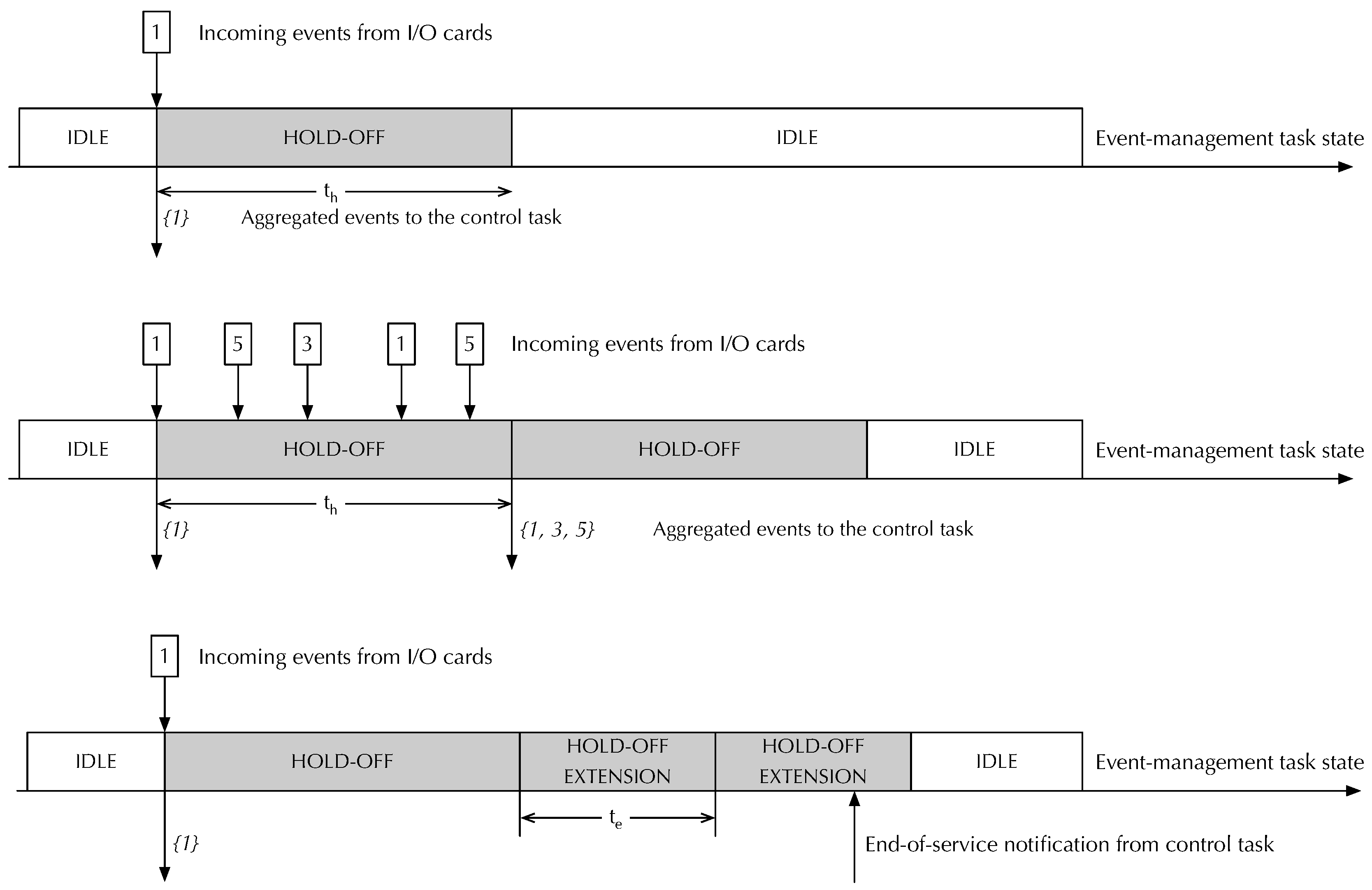
On the contrary, if the task receives one or more events during the hold-off period, as depicted in the middle diagram of Figure 5, it does not immediately send any additional event notification to the control task. Instead, it aggregates all incoming events into a single notification and sends it at the end of the hold-off interval. Then, it starts the hold-off interval again, thus repeating the process. For instance, if events originating from slaves 1, 3, and 5 arrive during a hold-off interval, the event management task will send a single notification to the control module at the end of the interval. The notification will contain the set of events .
Overall, the hold-off mechanism guarantees that events arriving while the task is idle reach the control task as soon as possible. At the same time, it also guarantees that events arriving during a hold-off interval are serviced after at most , while keeping the minimum interval between consecutive control task activations also at . To do this, the hold-off mechanism breaks the one-to-one relationship between events received from the I/O cards and notifications sent to the control task. Namely, multiple events arriving in quick succession will be gathered and result in a single notification being sent.
Moreover, an overload avoidance mechanism, also implemented by the event management task, may delay the generation of further notifications events towards the control task, by extending the hold-off interval, if the control task has not completely processed the previous event yet. An example of this mechanism is illustrated in the bottom diagram of Figure 5. It shows how, after initially delivering event set to the control task, the event management task kept extending the hold-off interval by until it received an end-of-service notification from the control task. During an hold-off extension the event management task handles incoming events as in a normal hold-off interval. Like , also is a configurable RtFw parameter with 1 ms resolution.
4.2. Selective I/O and Event Processing
When it receives an event notification, the control task surrounds the control function invocation with a special version of the I/O operations shown in Figure 3, modified for better I/O bus utilization. More specifically, before invoking the control function, it refreshes the PI input variables of the remote cards indicated by the event notification by means of a sequence of input transactions. The other input variables keep the value they assumed in the previous time-driven cycle. The rationale behind this approach is that while the control function is reacting to external events, it is crucial for it to operate on the most recent version of the PI input variables coming from the cards that generated them. On the contrary, the other input variables have not changed significantly, because the corresponding remote I/O cards did not generate any event, and hence their immediate refresh is unnecessary.
During execution, the control function will likely update some PI output variables to react to the event. It can signal these changes by invoking the macro RTFW_PI_MARK on them. When the control function returns, the control task look at the marks and performs a sequence of optimized output transactions that involve only marked variables. In case the control function does not mark any variables, the control task assumes the worst and refreshes all output PI variables. A full refresh of all PI variables, both input and output, is also performed when the event management system detects an internal overload or error, which led it to lose track of which remote I/O cards actually generated events.
5. System Configuration
System configuration lets users customize most of RtFw behavior, most importantly the mapping between PI variables and I/O points, as well as shared memories contents and their relationship with the PI variables themselves. Both mappings are specified in configuration files that contain a set of C macro invocations. This section focuses on Modbus boards as an example, but RtFw also implements a similar configuration mechanism for CANopen boards.
5.1. Board Instantiation and PI Variable Mapping
The I/O configuration file contains a sequence of macro invocations that determine which local or remote I/O devices, or boards, are expected to be present in the system. Boards are instantiated from a board database that specifies the capabilities of each class of boards, in terms of physical inputs and outputs. It will not be further discussed in this paper for conciseness. For example, an invocation of the macro BOARD_INSTANCE_MODBUS (shown in Figure 6) declares that a Modbus board is being configured. It has four arguments:
- The name of the class of boards it belongs to. This name must match one of the board classes defined in the database just mentioned.
- The name of the board instance being configured, which must be unique in the whole system and is used to resolve any ambiguity among boards belonging to the same class.
- The list of Modbus addresses the board may appear at, given as an argument to the MODBUS_ADDRESSES macro. It is used during initial bus scan to determine whether all boards mentioned in the system configuration are connected and their actual address on the bus.
- A sequence of macro invocations that map a subset of the physical inputs and outputs available on the board being configured to the corresponding PI variables.
Figure 6.
Example of Modbus board instantiation and PI variables mapping.
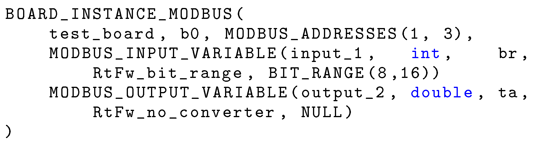
Each mapping macro invocation (within the fourth argument above) requires five arguments to fully specify a mapping:
- The name of one of the physical inputs or outputs mentioned in the board database for this class of boards.
- The data type of the PI variable that corresponds to it.
- The name of the PI variable. This is an ordinary C-language identifier that the control function can use to refer to the variable.
- The name of a conversion function, to convert the variable from its device-specific representation into a format suitable for the control function (for inputs) and vice versa (for outputs).
- A pointer to additional arguments specific to the conversion functions.
Therefore, the I/O configuration file excerpt shown in Figure 6 declares that board b0, belonging to board class test_board must be present on the bus at Modbus address 1 or 3. A field of 16 bits starting from bit 8 of its physical input input_1 is mapped to PI variable int br through the RtFw_bit_range converter. Moreover, its physical output output_2 is mapped to PI variable double ta, without conversion. At configuration time, RtFw checks that in the board database there is a board class called test_board, it has a physical input input_1 and a physical output output_2 of the appropriate size. Then, it generates the appropriate data structures that will be used to implement the mapping at runtime.
5.2. Data Structure Synthesis
As mentioned previously, RtFw configuration files are parsed at configuration time by the C preprocessor, in one or two passes, in order to transform them into data structures that RtFw will use later, at runtime. This approach enables RtFw to generate memory and CPU-efficient data structures, shifting most of the execution time overhead from runtime to configuration time, without sacrificing the expressive power of configuration statements.
The need for a second pass stems from the fact that the C macro preprocessor does not allow a macro to be defined during the expansion of a macro body [16]. On the contrary, when parsing configuration files, RtFw needs to generate multiple excerpts of C code based on the expansion of the macros cited in the configuration files, in order to define and fill different parts of the data structures that represent the system configuration. These excerpts of code must be strategically placed within more elaborate definitions, and hence, the most natural choice is to enclose them into macro bodies for delayed expansion.
To circumvent this issue, the body of the macros that need to define other macros introduce those definition with the special token __define__ rather than the usual #define that would trigger a preprocessor error. Then, a sed script translates the first token into the second and the output is fed to the C preprocessor once more. This approach has been chosen because, although it somewhat lacks generality, it is straightforward to implement and able to fulfill all RtFw requirements.
Figure 7 contains a simplified view of the data structures that RtFw synthesizes for input PI variable int br, declared as listed in Figure 6. Output PI variables are handled similarly. The tree-like data structure is rooted at the PI variables table, depicted at the bottom left of the figure. It has one element for each variable, which points to the description of the variable itself. Through a set of pointers, summarized near the top of the figure, RtFw can access other board-related data structures to retrieve the raw value of the variable from the device it resides on, during the I phase of the control cycle. More specifically, the available information specifies which board the value comes from, as well as its bus address and register address range.
Referring back to the PI variable descriptor, other pointers locate the converter function that RtFw also invokes during the I phase (RtFw_bit_range in this case) and its parameters (the integers 8 and 16). Finally, RtFw can also access the PI variable storage space through the descriptor, in order to store the converted value where the user-written control function can use it.
The choice of adopting a tree-like data structure in which the various nodes are linked by means of pointers instead of a monolithic structure has two distinct advantages:
- It becomes possible to save memory by sharing common information. For instance, all variable descriptors pertaining to variables whose value originates from the same board point to the same board descriptor.
- Most data can be stored in read-only Flash memory, reserving RAM (that is often a precious resource in low-cost embedded systems) for the actual read-write portions of the data structure. Referring back to Figure 7, the only read-write structures—to be stored in RAM—are the dark-gray-colored ones.
As shown in the figure, there are three main kinds of RAM-based information:
- The value of PI variables, br in this case.
- Status information about them, for instance, the outcome of the last I/O operation involving them.
- Status information about boards as a whole, for instance, the actual Modbus address of a board that has more than one possible configured address.
5.3. Shared Memory Configuration
Shared memory configuration is performed in a very similar way. Another configuration file must contain two macro invocations, one for output shared memory [B], the other for input shared memory [C]. Figure 8 shows an example of the first kind of configuration. The outer macro argument contains a sequence of invocations of the macro SHMEM_OUTPUT_VARIABLE, one for each shared variable. Individual invocations have four arguments:
- the data type and the name of the variable,
- an indication of whether any update to the variable should trigger a sporadic event directed to the control task,
- the mirroring configuration.
For instance, the first configuration item shown in Figure 8 states that the output shared memory shall contain a variable int br_shared. Its update shall not trigger any sporadic event indication (as specified by SHMEM_VARIABLE_NORMAL) and RtFw should automatically mirror its value from PI variable br. This configuration file has the same structure and is parsed in the same manner as the I/O configuration file shown in Figure 6 and discussed previously.
5.4. Proxy Access
The last configuration file to be discussed is the one used to configure proxy access. As described in Section 3.3, proxy tasks may be granted access to a subset of the contents of shared memories [B] and [C]. Access configuration, exemplified in Figure 9, consists of one invocation of the macro PROXY_VARIABLES, whose argument contains zero or more invocations of the macro PROXY_VARIABLE. Configuration takes places in two hierarchical steps:
- 1.
- The first step determines whether or not a shared variable is accessible to proxy tasks in general. More specifically, only variables mentioned as first argument of a PROXY_VARIABLE macro invocation are made accessible.
- 2.
- The second step specifies which proxy tasks get access, and provides additional mapping and conversion information specific to each access method. Namely, the second argument of PROXY_VARIABLE is a sequence of mapping macro invocations, one for each enabled access method.
Figure 9.
Example of proxy access configuration.
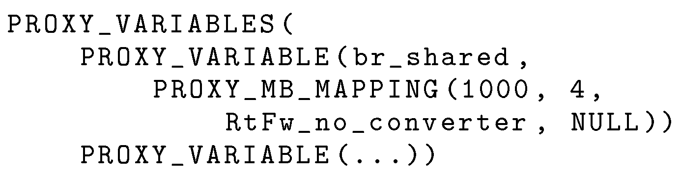
For Modbus-CAN and Modbus-TCP the mapping macro is named PROXY_MB_MAPPING. Its first two arguments specify the range of Modbus registers that serve the variable to external nodes, the third is the name of the converter to be used on the variable while serving it, and the fourth contains converter’s arguments. In the example shown in Figure 9, the shared variable br_shared is served, without conversion, when an external agent reads Modbus registers 1000–1003.
6. Internet Access
6.1. Requirements
As shown in Figure 1, modern embedded systems ought to be connected to the Internet to support a wide range of services, such as remote configuration, monitoring, diagnostics, and troubleshooting, also according to the industrial IoT paradigm [51]. Hence, it becomes necessary to grant the Internet-based management software (IMS) access to a portion of the embedded system state without disrupting real-time execution. In the case of RtFw, a convenient way to do so is to use a proxy, as described in Section 3.3. This approach has the advantage that access to real-time information from the Internet is always performed indirectly, through the proxy itself.
Within the controller card, introducing a clear separation of duties between the real-time and Internet-access parts of the system alleviates security concerns and makes the system more modular. At the same time, the assignment of appropriate priorities to the proxy tasks in charge of Internet access prevents them from interfering with real-time performance and timings. In addition, all peculiarities of the Internet access method chosen for a given system—for instance, wired versus WiFi network access, or specific data encryption and authentication protocols—can easily be confined to the proxy. As an example, Figure 2 shows how a proxy can grant access to part of the system state by means of an Ethernet-based Modbus-TCP connection through path ➉.
Under this premise, the main design problem to be solved is how to do so by means of abstract, symbolic variable names, while keeping the access mechanism as simple and efficient as possible. When symbolic names are known at compile time, they can be represented as values of an enumerated data type. On the contrary, names known only at run time are usually represented as variable-length strings of characters. The support for symbolic names is a key point to decouple the IMS—typically not developed by means of RtFw—from the embedded system firmware. This has the twofold advantage of protecting the IMS from internal firmware changes, while enabling its reuse for different but analogous embedded systems, provided they export the same set of symbolic variables.
6.2. Design and Implementation
The remote access method proposed in this paper is based on a two-step translation process relying on the collaboration between the controller card and the IMS, enabling them to share the workload. Even more importantly, the method has been designed so that at least part of the required computations can be performed at compile time. More specifically, the translation proceeds as follows:
- 1.
- The controller card and the IMS identify shared variables by means of unique values of an enumerated data type.
- 2.
- When necessary, the IMS resolves symbolic names represented as variable-length strings of characters into the corresponding enumerated values.
An additional upside of this approach is that, when multiple controller cards are present, the IMS can act as a centralized mapping point for all of them. Furthermore, shifting the workload towards the Internet node on which the IMS runs can be considered an advantage as well, because these nodes typically have more processing power than controller cards.
6.2.1. Shared Variables Enumeration
Regarding the first translation step, the underlying idea is that the controller card and the IMS have access to the shared variables configuration file described in Section 5 at compile time. From it, they can both generate an identical enumerated data type definition, together with the enumerated values associated with it, by means of the code listed in Figure 10. The code relies on techniques backed by the C language standard [16] and widely supported by C compilers like gcc. Moreover, this technique is commonly used in the implementation of various other open-source tools, such as the lwIP protocol stack [34].
With this approach, the enumerated values corresponding to the shared variable names are mentioned in the type definition in the same order as they appear in the configuration file when the C pre-processor scans the file. This is the same order followed when generating the input shared memory table for the controller card firmware. Considering that enumerated values are represented as integers by the compiler, and both enumerated values and array indexes start at zero, they can be used as an unambiguous index in the input shared memory table by both the controller card and the IMS.
For conciseness, the example code only shows how to generate the aforementioned data type definition from the declaration of input shared variables, but the same method is also appropriate for outputs. A finer-granularity, variable-by-variable approach is possible as well, such as the one shown for user interfaces and proxies in Section 3.3, at the expense of a higher complexity of the generation macros. However, this is not a concern because, being expanded at compile time, they do not introduce any runtime overhead.
For the same reason, the example generates a data type with a fixed name, shmem_input_var_name_enum, assuming that the IMS will communicate with a single controller card. When dealing with multiple cards, name clashes can easily be avoided by adding an appropriate, card-specific prefix or suffix to the data type name, by means of the C pre-processor token concatenation operator ## (double hash). This technique is already used in Figure 10 to add the prefix E_ to enumerated values, in order to avoid clashes with the corresponding input shared variable names, which are globally accessible.
6.2.2. Symbolic Name Translation
Moving on to the second translation step, a variety of well-known techniques are appropriate, also because this function is carried out by the IMS, where plenty of processing power is available. For instance, a hash function can be applied to the character string that holds the symbolic name, to derive the index of the corresponding entry in a hash table. An advantage of this approach is that it is quite straightforward and intuitive. However, it also has several downsides, typical of hash tables:
- The hash function may lead to a hash value that is quite large. Since this value indicates the position of a symbolic name in the hash table, the table itself may use a large amount of memory space, although only a small portion of its elements are filled with real data. On the other hand, a hash function with a smaller range incurs in a higher probability of collisions, thus reducing access efficiency.
- Even though the probability may be low, a hash conflict, which arises when multiple symbolic names are associated with the same hash value, cannot be ruled out. In this case, further checks and the overhead associated with them are needed to avoid operating on the wrong variable.
Regardless of the implementation technique, the macro substitution technique illustrated previously is still useful for generating most of the required data structures and code at compile time. As an example, Figure 11 shows how to synthesize a comparison function that takes as argument a character string and resolves it into an enumerated value. The synthesis is performed completely at compile time and relies on compiler optimizations to enhance code performance and reduce footprint. It is suitable to handle a relatively small number of symbolic names efficiently, without resorting to memory-hungry data structures and complex algorithms at run time. If the input-dependent execution time of the function is a concern, it is possible to work around it by always performing the comparison of the input argument against all the symbolic names before returning the result to the caller.
6.3. Comparison with Single-Step Translation
With respect to single-step translation methods, such as the aforementioned hashing performed directly on the controller card, the two-step approach just discussed offers distinct advantages.
- Firstly, the maintenance effort of the two-step approach is not significantly higher than the other. Indeed, the only requirement is that the IMS has access to a copy of the shared memory configuration files pertaining to all controller cards it is meant to communicate with, at compile time. Considering that this configuration information is determined very early in the design and development process and is unlikely to change during firmware lifetime, the maintenance effort related to those configuration files can be kept at a reasonable level.
- Furthermore, the method is bandwidth friendly because only enumerated values—represented as small, fixed-length integers in gcc—are exchanged between controller cards and the IMS, as opposed to longer, variable-length character strings. This is especially important when, to reduce system complexity and cost, a single bus is used for both remote access and real-time traffic, because it also limits the interference introduced by remote access.
Should a further consistency check between the view on shared variables of a controller card and the IMS become necessary, the controller card can still include the symbolic name (generated according to its own mapping) in its reply to an IMS request. This can be done with negligible interference with other, real-time activities because the extra processing it requires is limited. Even more importantly, since the controller card has full control on all the tasks running on it, as well as on how the real-time bus is utilized, it can choose to send back the reply at the most appropriate moment from both the processor and bus scheduling perspectives.
7. Performance Evaluation and Analysis
This part of the paper studies the overhead of RtFw in terms of execution performance and memory footprint. The testbed used for the experimental measurements consists of two boards equipped with an NXP LPC1768 ARM Cortex-M3 microcontroller [52] running at 100 MHz, one acting as controller card and the other as remote I/O card. The two cards are connected via a 1 Mb/s CAN bus and use Modbus-CAN to communicate. Since the default resolution of the FreeRTOS tick timer is only 1 ms and improving it would cause additional overhead, a dedicated 32-bit hardware counter that runs at the same frequency as the CPU clock and has negligible access overhead has been used to collect timestamps. Timestamps are stored in a dedicated, on-chip 32 KB bank of static RAM (SRAM).
Memory footprint evaluation has been performed statically, instead, on RtFw object code, by means of the size toolchain command. This command apportions footprint to three standard categories: text and read-only (RO) data, read-write (RW) initialized data, and read-write uninitialized data (BSS). These categories are important from a practical standpoint because, in an embedded system, they likely correspond to different kinds of memory. For instance, text and RO data can be stored in Flash memory (if available on the target) rather than RAM.
7.1. Time-Driven Execution Performance
The time-driven execution performance of RtFw has been evaluated by considering the general overhead imposed on cyclic execution by framework synchronization and Modbus I/O time, as well as the trend of I/O time as a function of the number of PI variables to be transferred. Accordingly, in the first part of the tests RtFw was configured to access one 16-bit input and one 16-bit output PI variable, each corresponding to a single Modbus register. Figure 12 illustrates which time measurements have been performed by means of a timing diagram. The diagram is organized vertically along the four operational layers that together implement synchronization and cyclic execution within RtFw.
The topmost layer is the FreeRTOS tick interrupt handler, executed every 1 ms. Besides using the handler to perform internal timekeeping activites—for instance, delayed task activation—FreeRTOS supports a timer hook function and invokes it from the handler on every tick. This provides a convenient timestamping point located very early in the RtFw cyclic synchronization chain. In the figure, represents the time needed to synchronize the first layer with the second. More specifically, it is the delay between the end of the hook and timer task activation, defined as the conclusion of its passive wait operation, implemented by means of the vTaskDelayUntil FreeRTOS primitive as described in Section 3.1. In turn, the timer task in the second layer triggers the activation of the control task in the third, passing through the event system also discussed in Section 3.1. Event propagation within RtFw takes an amount of time denoted as .
The control task performs most of the cyclic activities of RtFw, including the activation of the fourth and last layer, the user-written control function. Here, measurements have been focused solely on I/O operations, because the control function content is going to vary depending on user-level application requirements and measuring its execution time in a specific case would have had little practical significance. Moreover, as explained in Section 5, mirroring between PI and shared memory variables consists of a memory-to-memory copy involving data items of small size, which is negligible unless the number of variables being copied is atypically large.
Therefore, the measurements in the third layer are the total output time and the total input time . Each of them consists of local and Modbus communication. Then, Modbus communication time was further split up to evaluate the data gathering/scattering times, called and , respectively, as well as the output and input bus transaction times and . Local I/O time was not singled out because it was found to be negligible with respect to Modbus communication time.
Data gathering and scattering are an essential part of the Modbus I/O process because, for better efficiency, RtFw carries out bus transactions in aggregated form whenever possible. In other words, PI variables that are either all inputs or all outputs and are mapped to a contiguous range of addresses on the same board, are transferred in a single bus transaction. Aggregation decisions are taken just once before cyclic activities begin, and hence, do not contribute to RtFw overhead within the control cycle itself. On every cycle, however, it is still necessary to gather the PI variables to be aggregated and copy their values into the contiguous data buffer to be used for the output transaction. Symmetrically, after an input transaction has taken place, data retrieved from the remote I/O board must be copied into the corresponding PI variables, which are scattered through memory. Table 1 summarizes experimental results. For each delay, the mean value (), standard deviation (), and minimum and maximum value (Min and Max) are shown.
The main conclusion that can be drawn from those results is that overhead is dominated by Modbus CAN I/O time rather than RtFw. In turn, Modbus CAN I/O time depends for the most part on the CAN bus bit rate [39], which has already been set to the maximum in the experiments. More specifically, the total RtFw overhead for inter-layer synchronization and I/O setup can be written as
and its average in the experiments was . By contrast, the average Modbus CAN I/O time , expressed by
was . Therefore, represents less than 6% of the total overhead even when it is maximized by reducing the I/O time to the minimum (1 input and 1 output 16-bit I/O point). Another important aspect is the extremely low standard deviation of , which stayed consistently below what could be measured during the experiment. This confirms the suitability of RtFw for accurate real-time embedded applications, despite the higher level of abstraction it introduces in programming them.
The second part of the evaluation focused on the behavior of and as a function of the number of 16-bit I/O points. Results are shown in Table 2. The maximum number of I/O points considered in the experiments was 8 because typically Modbus I/O boards have between 2 and 8 analog inputs or outputs, each accessed by means of a 16-bit register [53]. The number of digital I/Os may be larger, but up to 16 of them are normally packed into the same I/O register. Besides confirming the expected direct dependency of and from the number of I/O points, the additional measurements confirm that the combined input and output standard deviation does not increase significantly and stays below 6 μs in all considered scenarios. The extra jitter incurred by when the number of I/O points exceeds 2 can be attributed to additional interference from the 1 ms RTOS tick handler that overlaps with the I phase of the control cycle in those cases, as also depicted in Figure 12.
7.2. Event-Driven Reactivity
The reaction time of RtFw to an external event originating from a remote I/O card, which is crucial for event-driven programming performance, has been evaluated in the scenario shown in Figure 13. It consists of the following steps:
- A remote Modbus I/O card generates an event and sends an asynchronous event notification message ➀ to the controller card via a real-time bus.
- The controller card firmware reacts by activating the event handling task and then the control task ➁.
- The control task performs a selective input operation ➂, activates the control function to handle the event ➃, and performs a selective output operation ➄.
Figure 13.
Framework timing diagram, event-driven execution. Bus traffic not shown for clarity.
The input and output operations that the controller card performs are seen by remote I/O cards as a sequence of Modbus register read and write operations, respectively. For writes, the timestamping point has been placed after the remote I/O card received the Modbus request from the controller card and the data to be written, but before it sent the corresponding acknowledgment. For reads, the timestamping point has been placed as soon as the remote I/O card becomes aware of the request. Therefore, represents the total reaction time of the controller card to a remote event, measured from event generation to the time at which the reaction becomes externally observable as a change of state of some of its outputs. Time , instead, is the earliest point in time when the remote I/O card that generated the event becomes aware that event handling has started.
Table 3 lists experimental results, as before, as a function of the number of 16-bit I/O points. The interval between consecutive remote event generations was set to a value greater than for the experiment, to avoid triggering the activation of event gathering and hold-off interval extension. Moreover, care has been taken to avoid any interference from time-driven activities while handling an event. As in the previous set of experiments, the control function content was kept to a minimum.
Barring measurement noise, remained constant as the number of I/O point varied. This was to be expected because a Modbus register read request has a fixed length, regardless of the number of registers to be read. Instead, depends on the number of I/O points because their values are transferred together with the Modbus register write request. What is more important, though, is that remained below 1.3 ms, even in the worst case, with a standard deviation below 4 μs, thus confirming that RtFw is able to respond to external events timely and consistently.
7.3. Memory Footprint
Table 4 contains information about the RtFw memory footprint, broken down into categories, namely:
- The base modules of the framework, comprising its real-time tasks (Section 3.1) and configuration data structures (Section 5).
- The Modbus and local real-time I/O modules.
- The Modbus RTU, CAN, and TCP proxies (Section 3.3).
- The shared memory management modules, including mirroring.
- Additional utilities, mainly consisting of functions to dump framework data structures in human-readable format as a high-level debugging aid.
- The main program of the application firmware, which initializes RtFw and implements a minimal control function.

Table 4.
Memory footprint divided by category.
| Category | Text + RO data (B) | RW Data (B) | BSS (B) |
|---|---|---|---|
| RtFw base | 6793 | 0 | 136 |
| I/O modules | 5384 | 0 | 0 |
| Proxies | 3112 | 0 | 40 |
| Shared memory management | 868 | 0 | 56 |
| Utilities | 6879 | 0 | 0 |
| Main program | 1481 | 0 | 2272 |
| Total | 24517 | 0 | 2504 |
The footprint measurement confirmed that RtFw can profitably be used even on extremely low-cost microcontrollers with limited memory resources. More specifically, its memory requirement amounts to less than 5% of the total Flash memory available on the LPC1768 (512 KB) and less than of 4% of its RAM (64 KB).
Besides RtFw, the application firmware must typically be linked against several additional libraries, for instance, the Modbus master and slave protocol libraries, the lwIP library, the FreeRTOS library, and the C runtime libraries. Their memory footprint has not been reported because they would still be needed even if RtFw were not used at all. Moreover, quantifying the exact memory footprint of these libraries would have been hard, because it highly depends on application-level code requirements and how the libraries themselves have been optimized. For instance, the C library heap can be reduced in size or eliminated completely if the application does not require dynamic memory allocation. Similarly, the C library newlib [54] offers specific configuration options for systems with limited RAM memory [55].
8. Conclusions
This paper described how RtFw—a firmware development framework aimed at speeding up application development and deployment with respect to plain C-language programming—has been designed and developed, highlighting its advantages with respect to related work. Besides showing how RtFw works internally, the design discussed here can also be useful as a reference to software practitioners willing to implement other comparable software modules. Offering support for both event-driven and time-driven programming makes RtFw future-proof without making it harder or less convenient to use.
In addition, the execution time overhead and memory footprint of a prototype implementation of RtFw have been experimentally evaluated with satisfactory results. All in all, results show that the higher-level programming paradigm supported by RtFw, with respect to C-language programming, can be profitably adopted to improve software quality, without sacrificing performance. This is true even on low-cost microcontrollers typically used in household consumer appliances and other IoT applications, often characterized by severe constraints on computing and memory resources, as well as power consumption.
Funding
This research received no external funding.
Data Availability Statement
The original contributions presented in this study are included in the article/supplementary material. Further inquiries can be directed to the corresponding author.
Conflicts of Interest
The author declares no conflicts of interest.
References
- Bigler, T.; Gaderer, G.; Loschmidt, P.; Sauter, T. SmartFridge: Demand Side Management for the device level. In Proceedings of the Proc. 16th IEEE Conference on Emerging Technologies and Factory Automation (ETFA), Piscataway, NJ, Sep. 2011; pp. 1–8. [Google Scholar] [CrossRef]
- De Silva, L.C.; Morikawa, C.; Petra, I.M. State of the art of smart homes. Engineering Applications of Artificial Intelligence 2012, 25, 1313–1321, Advanced issues in Artificial Intelligence and Pattern Recognition for Intelligent Surveillance System in Smart Home Environment. [Google Scholar] [CrossRef]
- Lobaccaro, G.; Carlucci, S.; Löfström, E. A Review of Systems and Technologies for Smart Homes and Smart Grids. Energies 2016, 9. [Google Scholar] [CrossRef]
- Choudhary, G.; Jain, A.K. Internet of Things: A survey on architecture, technologies, protocols and challenges. In Proceedings of the Proc. International Conference on Recent Advances and Innovations in Engineering (ICRAIE), Piscataway, NJ, Dec. 2016; pp. 1–8. [Google Scholar] [CrossRef]
- Aouedi, O.; Vu, T.H.; Sacco, A.; Nguyen, D.C.; Piamrat, K.; Marchetto, G.; Pham, Q.V. A Survey on Intelligent Internet of Things: Applications, Security, Privacy, and Future Directions. IEEE Communications Surveys & Tutorials 2024, 1–1. [Google Scholar] [CrossRef]
- Hakiri, A.; Gokhale, A.; Yahia, S.B.; Mellouli, N. A comprehensive survey on digital twin for future networks and emerging Internet of Things industry. Computer Networks 2024, 244, 110350. [Google Scholar] [CrossRef]
- Robinsha, S.D.; Amutha, B. Transportation networks that leverage internet of things architectures: A review. AIP Conference Proceedings 2025, 3162, 020114. [Google Scholar] [CrossRef]
- Fariha, A.; Alwidian, S.; Azim, A. A Systematic Literature Review on Requirements Engineering and Maintenance for Embedded Software. IEEE Access 2024, 12, 114263–114279. [Google Scholar] [CrossRef]
- Mok, W.Y. A Conceptual Model Based Design Methodology for MongoDB Databases. In Proceedings of the 2024 7th International Conference on Information and Computer Technologies (ICICT); 2024; pp. 151–159. [Google Scholar] [CrossRef]
- Umbarkar, S.; Admane, S. Advanced Embedded Software and Systems using MBD for Electrical Grid Stability. In Proceedings of the 2025 IEEE 14th International Conference on Communication Systems and Network Technologies (CSNT); 2025; pp. 1277–1280. [Google Scholar] [CrossRef]
- Benveniste, A.; Caspi, P.; Edwards, S.A.; Halbwachs, N.; Guernic, P.L.; de Simone, R. The synchronous languages 12 years later. Proceedings of the IEEE 2003, 91, 64–83. [Google Scholar] [CrossRef]
- Chen, J.; de Mendonça, J.L.V.; Ayele, B.S.; Bekele, B.N.; Jalili, S.; Sharma, P.; Wohlfeil, N.; Zhang, Y.; Jeannin, J.B. Synchronous Programming with Refinement Types. Proc. ACM Program. Lang. 2024, 8. [Google Scholar] [CrossRef]
- Samek, M. Practical UML Statecharts in C/C++, 2nd ed.; Newnes: Oxford, UK, 2008. [Google Scholar]
- Rempillo, C.; Mustafiz, S. STL4IoT: a statechart template library for IoT system design. SIMULATION 2025, 101, 213–239. [Google Scholar] [CrossRef] [PubMed]
- Navet, N.; Fejoz, L. CPAL: High-level Abstractions for Safe Embedded Systems. In Proceedings of the Proc. of the ACM International Workshop on Domain-Specific Modeling (DSM), New York, NY, USA; 2016; pp. 35–41. [Google Scholar] [CrossRef]
- International Organization for Standardization and International Electrotechnical Commission. ISO/IEC 9899, Information Technology — Programming Languages — C, 5th ed., 2024.
- Cibrario Bertolotti, I.; Hu, T.; Navet, N. Model-based design languages: A case study. In Proceedings of the Proc. 13th IEEE International Workshop on Factory Communication Systems (WFCS), Piscataway, NJ, May 2017; pp. 1–6. [Google Scholar] [CrossRef]
- Hu, T.; Cibrario Bertolotti, I.; Navet, N. Towards Seamless Integration of N-Version Programming in Model-Based Design. In Proceedings of the Proc. 22nd IEEE International Conference on Emerging Technologies and Factory Automation (ETFA), Piscataway, NJ, Sep. 2017; pp. 1–8. [Google Scholar]
- Altmeyer, S.; André, É.; Dal Zilio, S.; Fejoz, L.; Harbour, M.G.; Graf, S.; Gutiérrez, J.J.; Henia, R.; Le Botlan, D.; Lipari, G.; et al. From FMTV to WATERS: Lessons Learned from the First Verification Challenge at ECRTS (invited). In Proceedings of the Leibniz International Proceedings in Informatics (LIPIcs); Papadopoulos, A.V., Ed., Vienne, Austria, Jul. 2023; Vol. 262, 35th Euromicro Conference on Real-Time Systems (ECRTS 2023), pp. 19:1–19:18. [CrossRef]
- Bolton, W. Programmable Logic Controllers, 6th ed.; Newnes: Oxford, UK, 2015. [Google Scholar]
- CODESYS. Industrial IEC 61131-3 PLC programming, 2018. Available online: https://www.codesys.com.
- Strasser, T.; Rooker, M.; Ebenhofer, G.; Zoitl, A.; Sunder, C.; Valentini, A.; Martel, A. Framework for Distributed Industrial Automation and Control (4DIAC). In Proceedings of the Proc. 6th IEEE International Conference on Industrial Informatics (INDIN), Piscataway, NJ, Jul. 2008; pp. 283–288. [Google Scholar] [CrossRef]
- Fu, Y.; Gui, W.; Song, H. Smart Factory Design Based on CoDeSys. In Proceedings of the 2023 6th International Conference on Information Communication and Signal Processing (ICICSP); 2023; pp. 860–865. [Google Scholar] [CrossRef]
- Pinto, G.; Nunes, A.; Silva, L.; Pinto, R.; Pinheiro, J.; Ribeiro, A. Digital Factory: An Industrial Case Study for Function Block-Oriented Development. In Proceedings of the 2023 IEEE 9th World Forum on Internet of Things (WF-IoT); 2023; pp. 01–06. [Google Scholar] [CrossRef]
- International Electrotechnical Commission. IEC 61131-3, Programmable controllers — Part 3: Programming languages, 3.0 ed., 2013.
- Arduino AG. Arduino IDE, 2018. Available online: https://www.arduino.cc.
- Ávila, B.Y.L.; Vázquez, C.A.G.; Baluja, O.P.; Alexandru, M.; Cotfas, D.T.; Cotfas, P.A.; Domínguez, L.A.Q. Protothread and Cooperative Multitasking Scheduler on the Arduino Framework. In Proceedings of the 2024 International Conference on Applied and Theoretical Electricity (ICATE); 2024; pp. 1–5. [Google Scholar] [CrossRef]
- Buonocunto, P.; Biondi, A.; Lorefice, P. Real-time multitasking in Arduino. In Proceedings of the Proc. 9th IEEE International Symposium on Industrial Embedded Systems (SIES), Piscataway, NJ, Jun. 2014; pp. 1–4. [Google Scholar] [CrossRef]
- Restuccia, F.; Pagani, M.; Mascitti, A.; Barrow, M.; Marinoni, M.; Biondi, A.; Buttazzo, G.; Kastner, R. ARTe: Providing real-time multitasking to Arduino. Journal of Systems and Software 2022, 186, 111185. [Google Scholar] [CrossRef]
- Cibrario Bertolotti, I.; Hu, T. Modular design of an open-source, networked embedded system. Computer Standards & Interfaces 2015, 37, 41–52. [Google Scholar] [CrossRef]
- Farina, M.D.O.; Pohren, D.H.; Roque, A.d.S.; Silva, A.; da Costa, J.P.J.; Fontoura, L.M.; Anjos, J.C.S.d.; Freitas, E.P.d. Hardware-Independent Embedded Firmware Architecture Framework. Journal of Internet Services and Applications 2024, 15, 14–24. [Google Scholar] [CrossRef]
- Barry, R. Using the FreeRTOS Real Time Kernel – Standard Edition, 1st ed.; Lulu Press: Raleigh, North Carolina, 2010. [Google Scholar]
- ChaN. FatFs Generic FAT File System Module, 2018. Available online: http://elm-chan.org/fsw/ff/00index_e.html.
- Dunkels, A. lwIP – A Lightweight TCP/IP stack, 2018. Available online: http://savannah.nongnu.org/projects/lwip/.
- ISO. ISO 11898-1:2024 – Road vehicles – Controller area network (CAN) – Part 1: Data link layer and physical signalling. International Organization for Standardization, 2024.
- Cibrario Bertolotti, I.; Hu, T.; Ghafour Zadeh Kashani, G. A Low-Overhead Framework for Inexpensive Embedded Control Systems. In Proceedings of the Proc. 12th International Conference on Digital Telecommunications (ICDT), Wilmington, DE, Apr. 2017; pp. 7–12. [Google Scholar]
- Thondalapally, K.R. Event-Driven Architectures: The Foundation of Modern Distributed Systems. International Journal on Science and Technology 2025, 16. [Google Scholar]
- Pontarolli, R.P.; Bigheti, J.A.; Domingues, F.O.; de Sá, L.B.; Godoy, E.P. Distributed I/O as a service: A data acquisition solution to Industry 4.0. HardwareX 2022, 12, e00355. [Google Scholar] [CrossRef] [PubMed]
- Cena, G.; Cibrario Bertolotti, I.; Hu, T.; Valenzano, A. Design, verification, and performance of a MODBUS-CAN adaptation layer. In Proceedings of the Proc. 10th IEEE International Workshop on Factory Communication Systems (WFCS), Piscataway, NJ, May 2014; pp. 1–10. [Google Scholar] [CrossRef]
- CiA. CiA 301 V4.2.0 – CANopen application layer and communication profile. CAN in Automation e.V., 2011.
- Modbus-IDA. MODBUS Messaging on TCP/IP Implementation Guide V1.0b; Modbus Organization, Inc.: Hopkinton, MA, 2006. Available online: http://www.modbus-ida.org/.
- Modbus-IDA. MODBUS over Serial Line Specification and Implementation Guide V1.02; Modbus Organization, Inc., 2006. Available online: http://www.modbus-ida.org/.
- Walter, C. FreeMODBUS - A Modbus ASCII/RTU and TCP implementation. Available online: http://freemodbus.berlios.de/.
- Embedded Solutions. Modbus Master. Available online: http://www.embedded-solutions.at/.
- Tisserant, E.; Dupin, F.; et al. Free software CANopen framework. Available online: https://canfestival.org/.
- ISO. ISO/IEC/IEEE International Standard: Telecommunications and exchange between information technology systems – Requirements for local and metropolitan area networks – Part 1Q: Bridges and bridged networks. ISO/IEC/IEEE 8802-1Q:2024(en) 2024, pp. 1–2166. [CrossRef]
- Baker, T.P.; Shaw, A. The cyclic executive model and Ada. In Proceedings of the Proc. IEEE Real-Time Systems Symposium (RTSS), Piscataway, NJ, Dec. 1988; pp. 120–129. [Google Scholar] [CrossRef]
- Caccamo, M.; Baker, T.; Burns, A.; Buttazzo, G.; Sha, L. Real-Time Scheduling for Embedded Systems. In Handbook of Networked and Embedded Control Systems; Hristu-Varsakelis, D., Levine, W.S., Eds.; Birkhäuser Boston: Cambridge, MA, 2005; pp. 173–195. [Google Scholar] [CrossRef]
- Modbus-IDA. MODBUS Application Protocol Specification V1.1b; Modbus Organization, Inc.: Hopkinton, MA, 2006; Available online: http://www.modbus-ida.org/.
- Locke, C.D. Software architecture for hard real-time applications: cyclic executives vs. fixed priority executives. Real-Time Systems 1992, 4, 37–53. [Google Scholar] [CrossRef]
- Bloom, G.; Alsulami, B.; Nwafor, E.; Cibrario Bertolotti, I. Design patterns for the industrial Internet of Things. In Proceedings of the Proc. 14th IEEE International Workshop on Factory Communication Systems (WFCS), Jun. 2018; pp. 1–10. [Google Scholar] [CrossRef]
- NXP B.V. LPC1769/68/67/66/65/64/63 Product data sheet, rev. 6, 2010. Available online: http://www.nxp.com/.
- Moxa Inc. Modular I/O product series, 2018. Available online: https://www.moxa.com/product/Modular_IO.htm.
- Chamberlain, S.; Pesch, R.; Red Hat Support.; Johnston, J. The Red Hat newlib C Library, libc 2.2.0. Red Hat Inc., 2014.
- Cibrario Bertolotti, I. RTOS Support in C-Language Toolchains. In Proceedings of the Proc. 18th IEEE International Conference on Industrial Technology (ICIT), Piscataway, NJ, Mar. 2017; pp. 1328–1333. [Google Scholar] [CrossRef]
Figure 1.
Architecture of an RtFw-based control system.
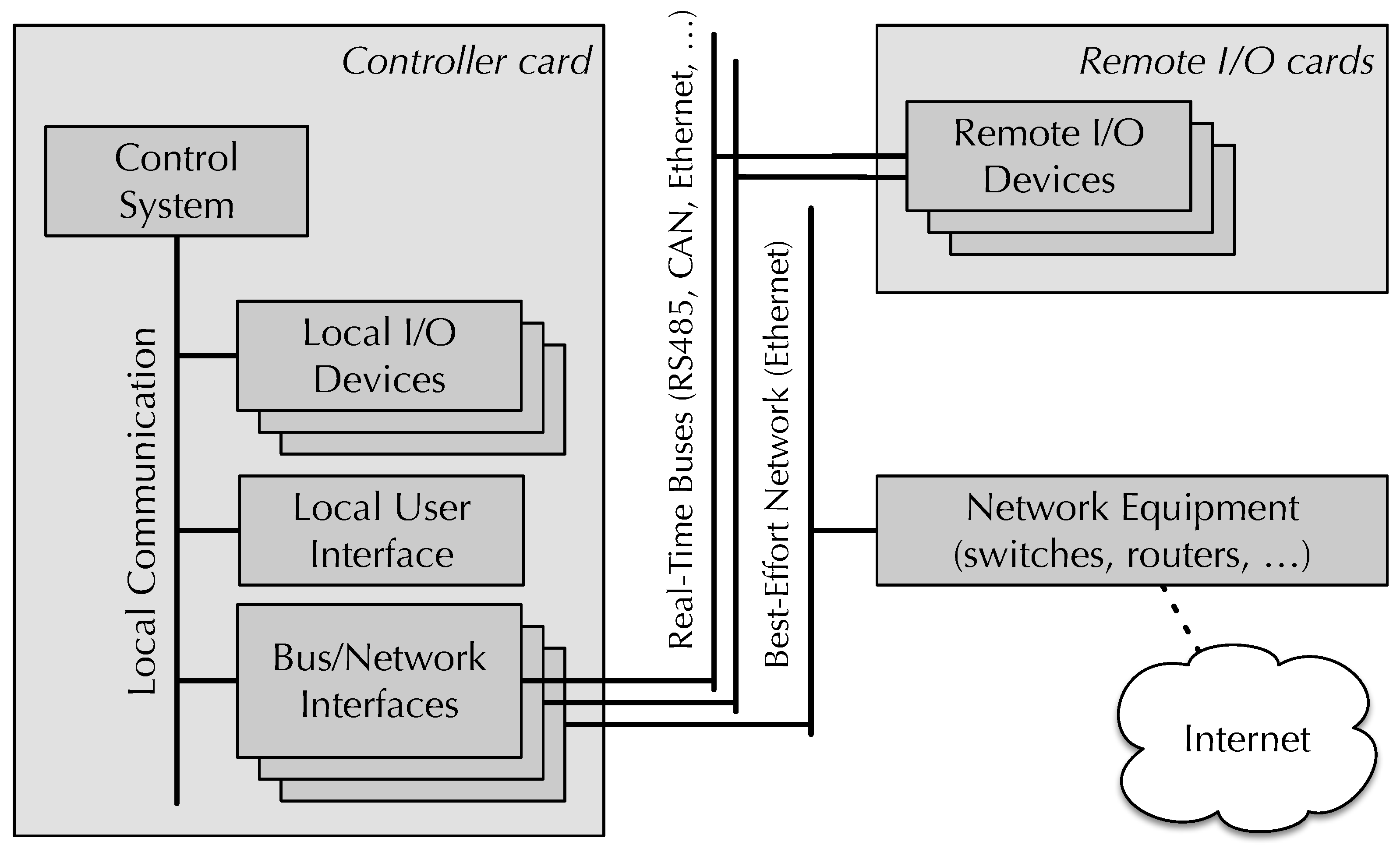
Figure 2.
Structure of the core framework components.
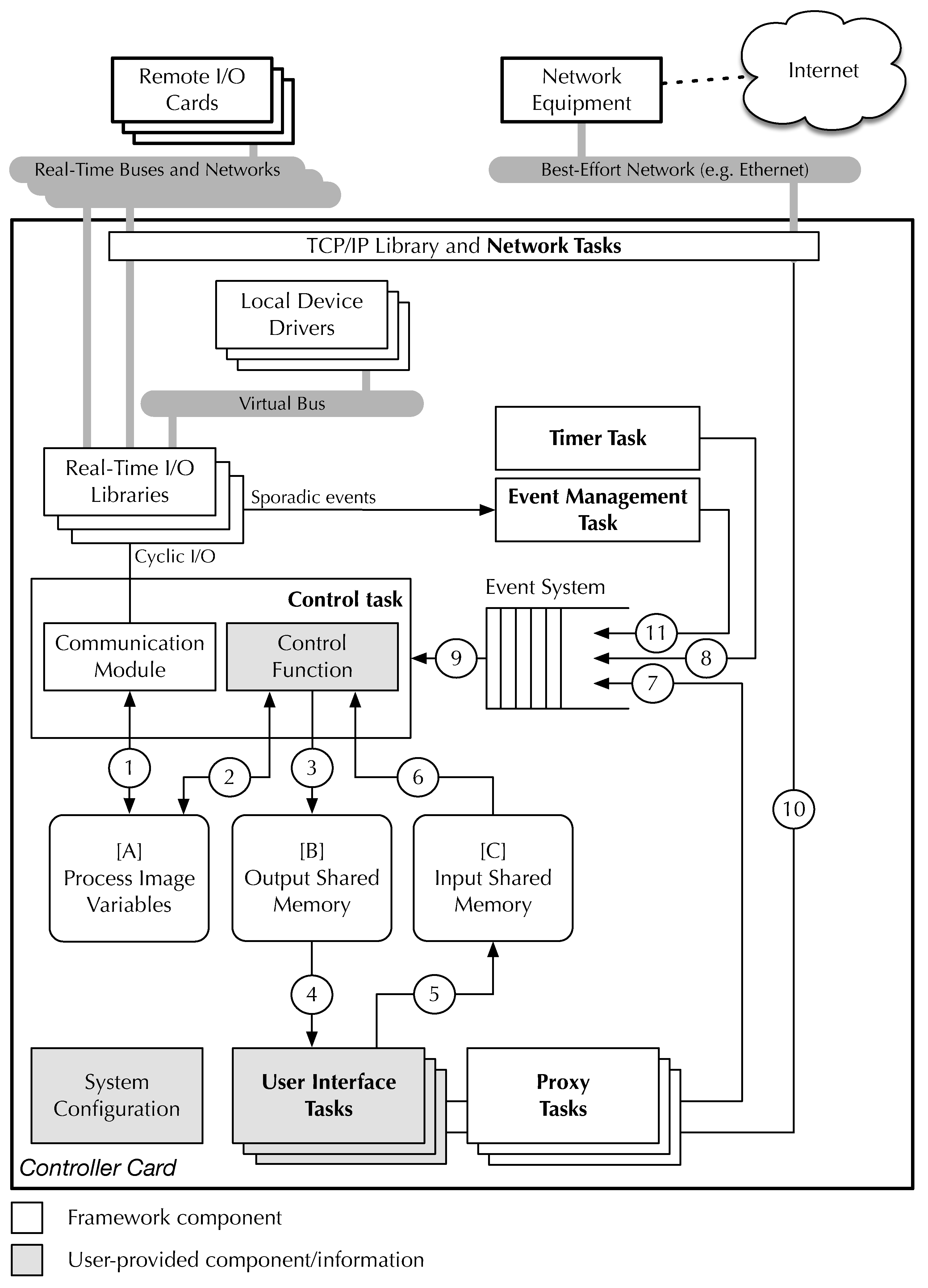
Figure 4.
Relationship between the event management task and other RtFw components.
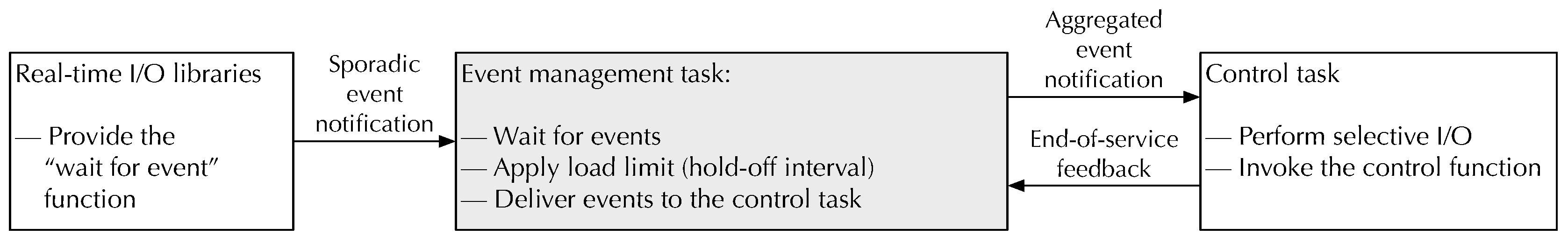
Figure 7.
RtFw-generated data structures for variable br of Figure 6.
Figure 7.
RtFw-generated data structures for variable br of Figure 6.
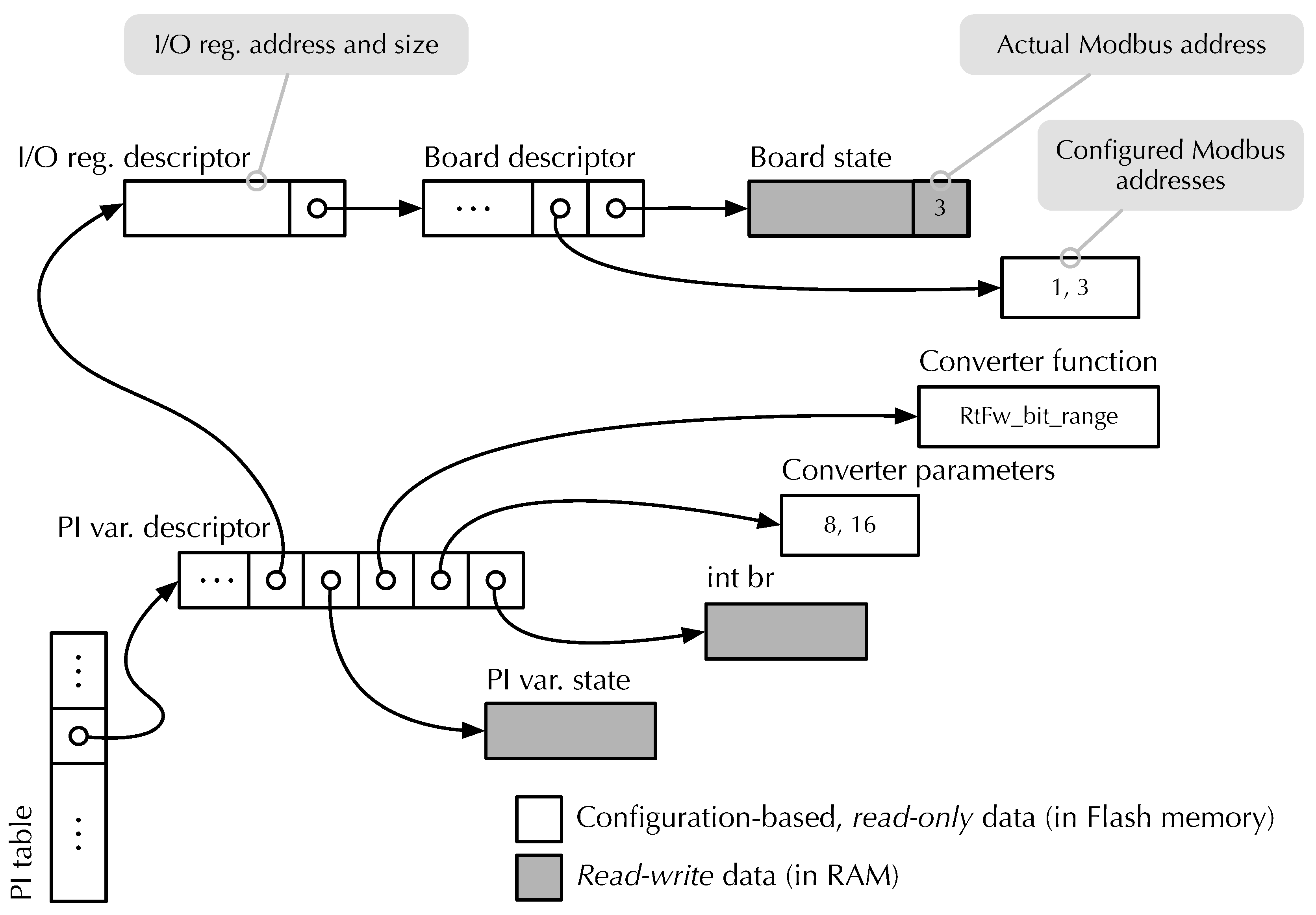
Figure 8.
Example of (output) shared memory configuration.
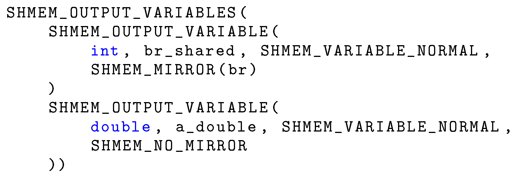
Figure 10.
Generation of the enumerated data type for Internet access to shared (input) variables.
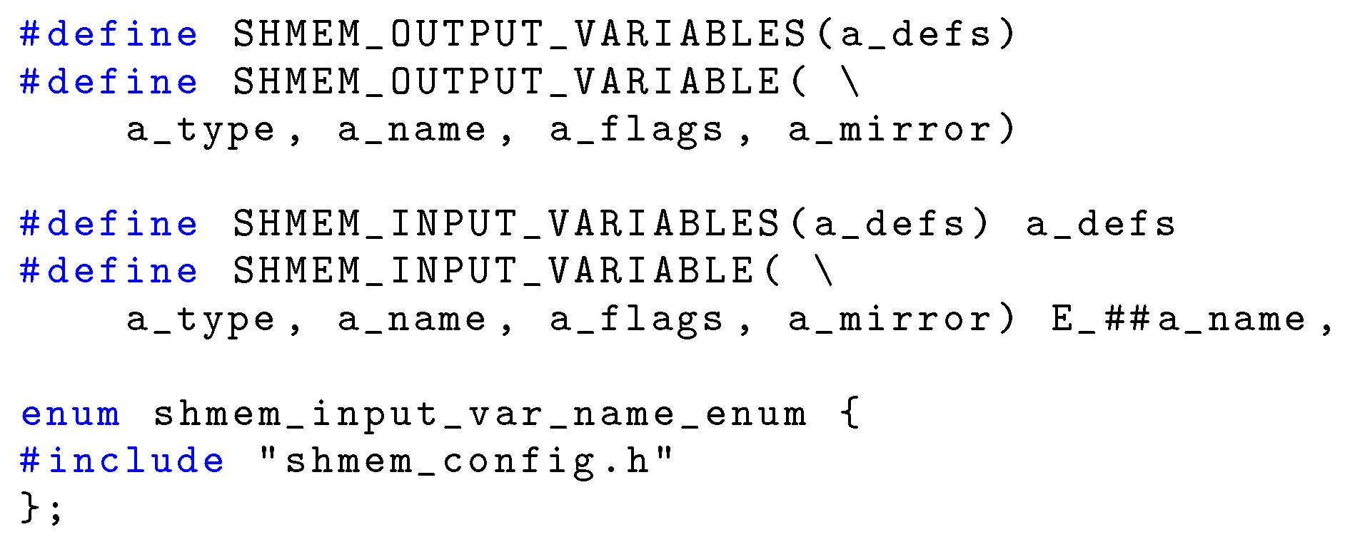
Figure 11.
Direct code generation for resolving symbolic names into symbolic values.
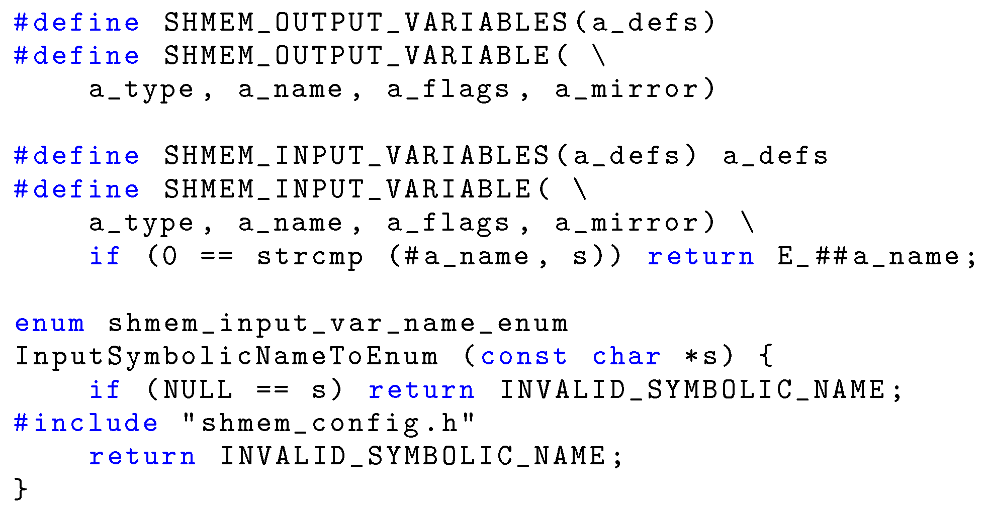
Figure 12.
Framework timing diagram, time-driven execution.
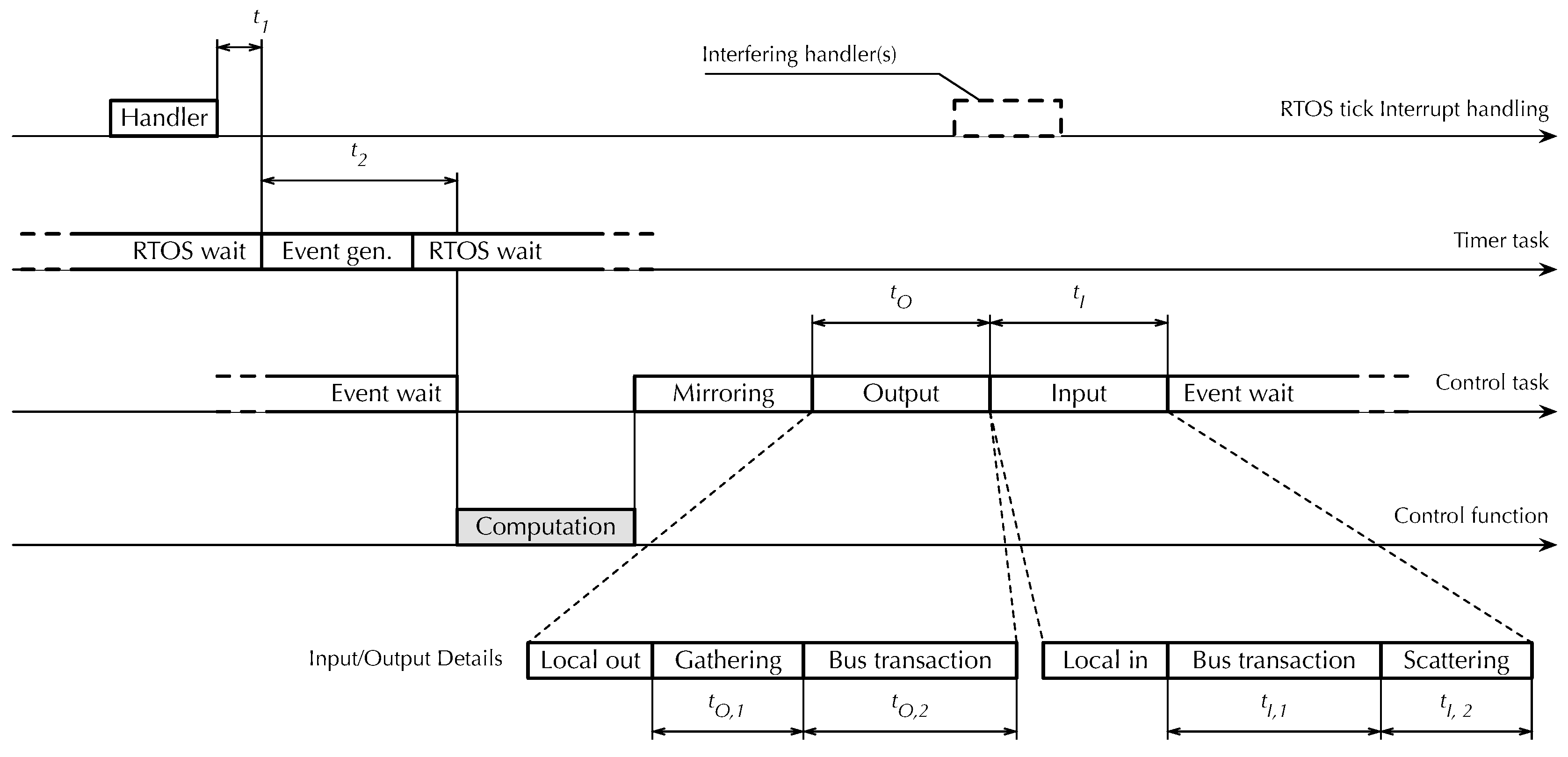
Table 1.
Measurement of the delays shown in Figure 12, 490 sample points.
Table 1.
Measurement of the delays shown in Figure 12, 490 sample points.
| Operation | Delay () | ||||
|---|---|---|---|---|---|
| Min | Max | ||||
| Local Operations | |||||
| (timer task activation) | 3.46 | 0.00 | 3.46 | 3.46 | |
| (control function activation) | 18.75 | 0.06 | 18.69 | 18.89 | |
| Output Operations, 1 16-bit I/O point | |||||
| (Gathering) | 11.61 | 0.00 | 11.61 | 11.61 | |
| (Output bus transaction) | 398.58 | 0.83 | 396.81 | 400.82 | |
| (Total) | 410.19 | 0.83 | 408.42 | 412.43 | |
| Input Operations, 1 16-bit I/O point | |||||
| (Input bus transactions) | 276.96 | 1.09 | 274.80 | 279.90 | |
| (Scattering) | 3.59 | 0.00 | 3.59 | 3.59 | |
| (Total) | 280.55 | 1.09 | 278.39 | 283.49 | |
Table 2.
Behavior of and as a function of the number of 16-bit I/O points, 490 sample points.
| Number of outputs | Total delay (μs) | |||
|---|---|---|---|---|
| Min | Max | |||
| 1 | 410.19 | 0.83 | 408.42 | 412.43 |
| 2 | 428.00 | 0.64 | 426.56 | 430.15 |
| 4 | 524.22 | 0.62 | 522.87 | 525.78 |
| 8 | 663.05 | 1.45 | 660.05 | 665.68 |
| Number of inputs | Total delay (μs) | |||
| Min | Max | |||
| 1 | 280.55 | 1.09 | 278.39 | 283.49 |
| 2 | 360.54 | 1.59 | 357.83 | 367.03 |
| 4 | 405.67 | 3.41 | 398.87 | 415.32 |
| 8 | 544.20 | 3.91 | 536.81 | 557.93 |
Table 3.
Event-driven reactivity, and of Figure 13, as a function of the number of 16-bit I/O points, 490 sample points.
Table 3.
Event-driven reactivity, and of Figure 13, as a function of the number of 16-bit I/O points, 490 sample points.
| Number of I/O points | Event to input (μs) | Event to output (μs) | ||||||
|---|---|---|---|---|---|---|---|---|
| Min | Max | Min | Max | |||||
| 1 | 315.19 | 0.67 | 313.75 | 316.77 | 709.32 | 1.15 | 706.86 | 713.53 |
| 2 | 314.12 | 0.72 | 312.72 | 315.71 | 811.35 | 2.24 | 807.33 | 818.12 |
| 4 | 316.20 | 0.65 | 314.69 | 317.74 | 953.94 | 2.73 | 948.61 | 961.69 |
| 8 | 318.46 | 1.36 | 316.69 | 322.67 | 1241.20 | 3.93 | 1232.23 | 1255.63 |
Disclaimer/Publisher’s Note: The statements, opinions and data contained in all publications are solely those of the individual author(s) and contributor(s) and not of MDPI and/or the editor(s). MDPI and/or the editor(s) disclaim responsibility for any injury to people or property resulting from any ideas, methods, instructions or products referred to in the content. |
© 2025 by the authors. Licensee MDPI, Basel, Switzerland. This article is an open access article distributed under the terms and conditions of the Creative Commons Attribution (CC BY) license (http://creativecommons.org/licenses/by/4.0/).
Copyright: This open access article is published under a Creative Commons CC BY 4.0 license, which permit the free download, distribution, and reuse, provided that the author and preprint are cited in any reuse.


