Submitted:
19 May 2025
Posted:
20 May 2025
You are already at the latest version
Abstract
This project is the implementation and design of a secure and scalable local area network (LAN) for a midsized organization using Cisco Packet Tracer as the simulator software. The methodology involved eight key phases: requirement analysis, hierarchical network design, IP addressing and subnetting, device configuration, client installation, connectivity testing, troubleshooting, and final documentation. A Layered three-layer architecture (access, distribution, and core) was adopted to enhance manageability and performance. Security and segregation were enforced using VLANs and subnetting, while DHCP and static addressing were used to manage IPs effectively. Wired and wireless access was configured on devices, with separate SSIDs for employee and guest networks using WPA2 encryption. Routing protocols such as RIP and OSPF were used to facilitate effective inter-network communication. Extensive testing and optimization ensured the functionality, robustness, and scalability of the network. This deployment gives a good foundation for enterprise networking scenarios in real-world environments and offers a good foundation for future development
Keywords:
VLAN
; DHCP
; OSF Network
; Security
; Robustness
1. Introduction
The aim of this project is to design, model, and execute a stable Local Area Network (LAN) for a midsized company using Cisco Packet Tracer. The network shall provide for a maximum of 30 workers and their corresponding devices like laptops, desktops, mobile phones, and guest users. In addition to conventional client devices, the architecture incorporates Internet of Things (IoT) devices such as webcams and smart door locks to make the network current, scalable, and future-proof for technological demands yet to emerge. The network must also offer secure and reliable connections to internal and external servers to support the company's day-to-day operations and data needs[1,2].
To begin with, there was an extensive analysis of business requirements. This included considering the wired and wireless connectivity requirements, the number and nature of devices to be supported, as well as security requirements to protect sensitive business data. Based on this assessment, there was a deployment of a hierarchical network design model to enhance manageability, performance, as well as scalability in the long run. This design includes core, distribution, and access layers that logically organize the network and facilitate easy troubleshooting and maintenance[3].
Implementation entailed several important steps. IP address schemes were first designed using static or dynamic addressing depending on device type and network segment. Subnetting was employed to organize the network in an efficient way and enhance security. Network hardware, including routers, Layer 2 and Layer 3 switches, and wireless access points, was installed to provide faultless connectivity in the LAN. VLANs were utilized to compartmentalize traffic between departments and improve security overall. Wireless networks were established using SSIDs for employees and visitors, including encryption standards like WPA2 to secure wireless communications[4,5,6,7,8,9].
Connectivity testing was an integral part of the project. It involved checking connections between all devices to ensure that the network provided access to necessary services while isolating unauthorized access. Furthermore, routing protocol configuration like RIP or OSPF ensured correct data exchange across different network segments and any external networks connected[10,11,12,13,14,15].
Through this practical project, we gained significant practical experience with network management and design[16,17]. Using Cisco Packet Tracer, we were able to model real-world environments, discover and correct configuration errors, and reinforce our theory-based networking principles with real-world practice. The finished network design addresses all the company's requirements and places the central elements of basic networking such as reliability, security, performance, and scalability at the top. The project not only serves the technical purpose but also prepares us for actual problems in enterprise networking situations[18,19,20].
2. Methodology
1. Requirement Analysis
The project began with an in-depth analysis of the firm's business and technical requirements. This included defining the number and type of devices (desktops, laptops, mobile phones, IoT devices), user capacity (up to 30 workers) estimation, and security and connectivity needs for wired and wireless networks[21].
2. Network Design
A hierarchical network design model was used, dividing the network into access, distribution, and core layers. The model is more manageable, scalable, and performant. Features that were included are:
- Subnetting to efficiently organize devices and bolster security
- VLANs to separate departmental traffic and safeguard sensitive data
- Planning for employee and visitor wireless networks, each with distinct SSIDs and WPA2 encryption
3. IP Addressing and Subnetting
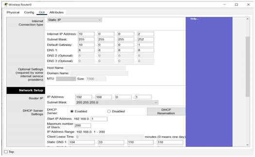
An IP addressing scheme was put in place, using static or dynamic addressing based on device roles. DHCP was enabled on the wireless router to automatically assign IPs within a specific range (192.168.0.1 to 192.168.0.200), while static IPs were assigned to servers and network devices.
4. Device Configuration
Wireless Router: Assigned a LAN IP (192.168.0.1), subnet mask (255.255.255.0), and DHCP service. The Internet interface of the router was configured to talk to the core router with a point-to-point subnet (10.0.0.0/30).
Router: Static routes were set up to forward traffic between the external and internal networks. NAT was set up to provide secure access from internal devices to external resources.
Switches and Access Points: Deployed to provide secure wired and wireless access throughout the network.
5. Client Device Configuration
Client devices (laptops, PCs, smartphones) were configured to connect through DHCP. Wireless modules were installed in laptops and devices were tested for network connectivity.
6. Connectivity Testing and Verification
Comprehensive connectivity testing was performed to confirm all devices could access required services and resources, and unauthorized use was prohibited. Routing protocols (RIP or OSPF) were configured and tested for effective data transmission between segments.
7. Troubleshooting and Optimization
Barriers such as selecting the appropriate routers, server configuration, and topology optimization were resolved through repetitive testing and debugging. Parameters were optimized for maximum performance, dependability, and security.
8. Documentation and Review
All the steps, settings, and design decisions were documented. The resultant network was tested to ensure that it met all provided requirements for reliability, security, scalability, and future growth.
This method gave a secure, stable, and scalable network design, closely replicating real-world enterprise networking scenarios using Cisco Packet Tracer.
3. Physical Workspace
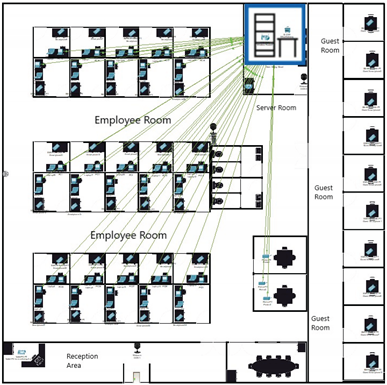
3.1. Build a Simple Network in the Logical Topology Workspace
| Explanation | Screenshot |
| The image shows multiple smartphones connected wirelessly to the network. These are the required 30 smartphones that the employees will be using. It is also worth noting that the connection is wired. |
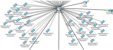 |
| The second image highlights the wireless connections for employee laptops. Each laptop is linked to the network, to make sure they are all connected and Ready to use. The connection is also wireless, so it is more convenient. |
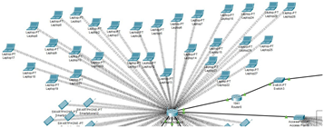 |
| This picture displays the wired connections of PCs and printers to switches. Each employee has a PC connected via Ethernet. Notice how This setup has a wired connection for reliability and a faster connection. Printers are also wired to the switch. | 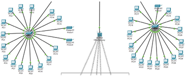 |
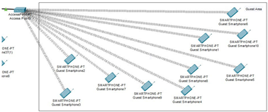
| This occupied area is the guest room, where a maximum of 10 people can fit inside. The phone connections are all wireless. All the devices get their connection from access point directly connected to the wireless router. |
 |
| For providing the wireless connection to 10 guest devices. access point is used, and inside the configuration of port 1 of the access point, the SSID is set as Guest and in authentication, WPA2-PSK is selected, which assigns login information for each device for them to connect to the network as an added security measure. | 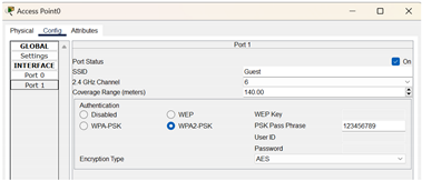 |
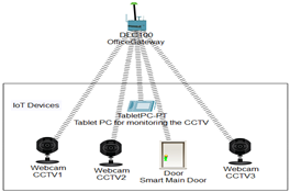
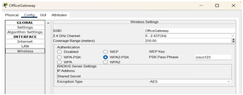
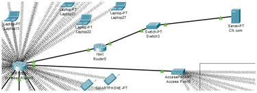
| The IoT devices section contains 3 webcams (one for the main door, one for employee space, and one for the server room), a smart door that can be opened and closed, and a tablet PC to monitor these devices. All the IoT devices are connected to a home gateway (renamed to OfficeGateway) while the gateway is connected to the wireless router via a copper straight-through wire. |
 |
| The tablet PC is used to monitor the IOT devices. Inside the desktop, click on the IOT monitor, and you will be able to check all the IOT devices. | 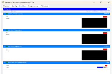 |
| Inside the config of HomeGateway, the SSID is changed to OfficeGateway and for extra security measures in authentication, WPA2-PSK is selected, which assigns login information for each IOT device and connects them to the network. |
 |
| The WRT300N wireless router is connected to the server through a 1941 router, which gets its connection from a switch. The reason for choosing a 1941 router is that it is specifically designed for small-to-medium-sized businesses and can handle multiple connections all at once, all while having a wired connection option as well. As for the WRT300N wireless router, it is used for mobile devices, computers, and laptops on most occasions, all while being affordable and having a decent range. |
 |
| Inside the config of wireless router, the SSID is set as OfficeNetwork and for security in the authentication, we selected WPA2-Enterprise (WiFi Protected Access 2), which assigns login information for each device for them to connect to the network. | 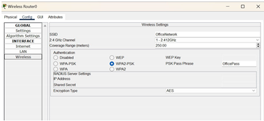 |
Configure the Network Devices
- 1)
- Configuration for Wireless_Router0
Click on the wireless router0 and go to the GUI tab to access the settings
Set LAN IP to 192.168.0.1 and Subnet Mask to 255.255.255.0 as stated in the
requirements and enable DHCP. The starting IP for devices is 192.168.0.1 and the maximum number of users is 200, which sets the IP Address Range from 192.168.0.1 to 192.168.0.200.
The Static DNS 1 is set to 104.33.110.110 to ensure communication from the external server.
The Internet interface above is configured to allow Wireless_Router0 to communicate with an external network such as CN.com. The Internet IP Address 10.0.0.2 has the same network IP as Router0’s Gig0/1. The subnet 10.0.0.0/30 only allows for two usable IPs, which are 10.0.0.1 for Router0 and 10.0.0.2 for Wireless_Router0.
Configuration for Router0
Before configuring the interfaces, it is important to configure the static route to forward packets from 192.168.0.0/24 to 10.0.0.2. We have to use the CLI in Router0 to configure the IP route, using the command “ip route 192.168.0.0 255.255.255.0 10.0.0.2”.
We also configured each interface NAT to allow devices in 192.168.0.x range to
communicate with external IPs like 104.33.110.110 by translating internal IPs to the external IPs range.
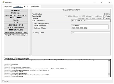
3.2. Interface GigabitEthernet0/1
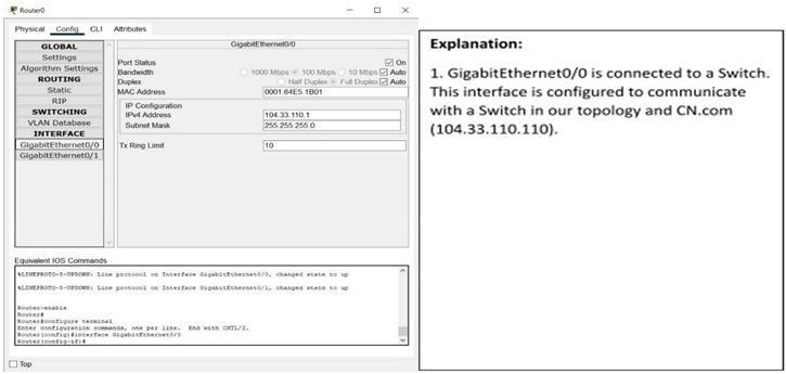
Interface GigabitEthernet0/0
- 3)
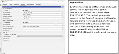
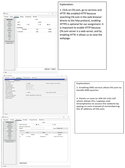
- Configure CN.com
- 4)
- Configuring Client Devices
Configuring PCs, Laptops and Smartphones:
3.3. Verify Connectivity
| Steps | Explanation | Screenshot |
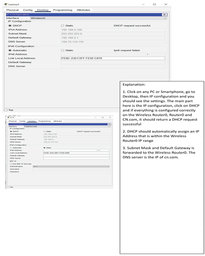
| Step 1: Refresh the IPv4 | We have opened the PC | 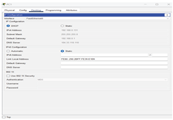 |
| settings on the PCs | window and selected Desktop | |
| from the menu. Then we | ||
| opened the IP Configuration | ||
| window and chose DHCP | ||
| instead of Static. We made | ||
| sure that the computer had an | ||
| IP address, Subnet Mask, and | ||
| Default Gateway. | ||
| In this step we tested connecting to a CN.com server Open the Command Prompt window from the Desktop menu, choose Command Prompt. Then we wrote the ping code CN.com to test it and it was working and there are no problems |
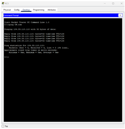 |
|
| Step 2: Refresh the IPv4 settings on the Laptops | We have opened the laptops window and selected Desktop from the menu. Then we opened the IP Configuration window and chose DHCP instead of Static. We made sure that the computer had an IP address, Subnet Mask, and Default Gateway |
 |
| In this step we tested connecting to a CN.com server Open the web Browser window from the Desktop menu, we type CN.com in the search bar to make sure that the site is working well |
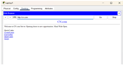 |
|
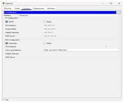
| Step 3: Refresh the IPv4 settings on the Mobile Phones |
We have opened the Smartphones window and selected Config from the menu. Then we chose DHCP instead of Static. We made sure that the computer had an IP address, Subnet Mask, and Default Gateway | 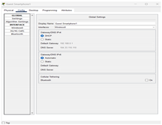 |
| In this step we tested connecting to a CN.com server Open the web Browser window from the Desktop menu inside the smartphone, we type CN.com in the search bar to make sure that the site is working well |
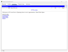 |
|
| Step 4: Refresh the IPv4 settings on the Router | It seems that the router does not have an explicitly dedicated WAN interface, but only GigabitEthernet0/0 and GigabitEthernet0/1 interfaces. Any Ethernet interface can be used as a WAN interface by configuring it correctly. |  |
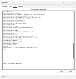
| In this step, configure the GigabitEthernet interface as a WAN interface Choose CLI from the router window Enter the settings mode Type the enable code configure terminal Select GigabitEthernet0/1 as external interface (WAN) Type the code interface GigabitEthernet0/0 IP address 104.33.110.1 255.255.255.0 no shutdown Set NAT on this interface as external interface Type the code ip nat outside Check the connection to the DHCP server Type the code ip address dhcp |
 |
|
| Then make sure the default route ip route 0.0.0.0 0.0.0.0 10.0.0.1 make sure the GigabitEthernet0/1 interface (internal) has the ip nat inside command |
||
| We made sure that the CN.com works correctly and there are no problems by writing the code in the CLI interface |
 |
Wireless_Router0 is configured as shown by a graphical user interface (GUI) tab that shows both Internet and LAN configurations. The LAN configuration is given an IP address of 192.168.0.1 and a subnet mask of 255.255.255.0. DHCP is also activated from IP 192.168.0.1 with a capacity to serve 200 users, thereby defining the IP range from 192.168.0.1 to 192.168.0.200. In addition, Static DNS 1 is set to 104.33.110.110, which offers domain name resolution from the external DNS server. The Internet section indicates the wireless router to be connected to the external network with IP 10.0.0.2, subnet mask 255.255.255.252, and gateway IP 10.0.0.1, which is the internal IP of Router0, enabling routing to external networks.
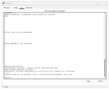
For Router0, the configuration is via the CLI (Command Line Interface). It shows a static routing command: ip route 192.168.0.0 255.255.255.0 10.0.0.2, which directs traffic for the 192.168.0.0/24 network via Wireless_Router0. NAT (Network Address Translation) is configured by tagging the internal interface with ip nat inside and the external interface with ip nat outside. An access-list is utilized to define local traffic, and ip nat inside source list translates internal IPs to a public IP. The GigabitEthernet0/1 interface is shown with IP 10.0.0.1, subnet 255.255.255.252, directly connected to the Wireless_Router0. Its default settings like bandwidth and MAC are not changed. The GigabitEthernet0/0 interface is assigned IP 104.33.110.1 with subnet 255.255.255.0, and is configured as the outside (WAN) interface with ip nat outside. It can also use DHCP according to circumstances.
For CN.com setup, the image is likely showing a server installation window with domain CN.com, and a public IP address, e.g., 104.33.110.x. DNS and web services have been installed in the server with the web server module to answer HTTP requests.
For client-side settings, the physical tab of the laptop shows WRT300N in place of the standard wireless module to support wireless networking. In the desktop tab, DHCP is chosen and it auto-configures IP settings. For PCs, the desktop interface shows DHCP-selected IP configuration; similar to the laptop, a valid IP, subnet, and gateway are retrieved from Wireless_Router0. Smartphones are placed in the config tab, showing wireless interface configurations with DHCP enabled and auto-assigned IP details.
In connectivity confirmation, PCs are shown via Command Prompt successfully pinging CN.com, where responses are shown and no packet loss. Laptops and smartphones use web browsers, where the typing of CN.com in the address bar successfully loads the page, confirming Internet connection. Finally, in Router CLI, the WAN parameters would be configured by using commands like interface GigabitEthernet0/0, ip address 104.33.110.1 255.255.255.0, and ip nat outside. When DHCP is being used, IP assignment will be dynamic. Command ip route 0.0.0.0 0.0.0.0 10.0.0.1 ensures default routing, and another ping to CN.com confirms the entire network's access to the internet.
4. Challenges
Throughout the process of choosing the best network design and server and router configuration for this project, we were faced with a chain of problems. Most challenging was choosing an adequate router type to meet the needs of the network due to the need to reconcile cost and performance. We needed to revise numerous drafts before developing a plan that satisfied project requirements without being too complex and inefficient, so network topology design was yet another demanding activity.
Configuring the server to facilitate smooth connectivity and correct interactions with other networked devices was another challenge. It took a lot of research, debugging, and effort to resolve them, and eventually, we created a basic but fully operational network layout in Cisco Packet Tracer. It provided us with valuable problem-solving experience and highlighted the importance of flexibility and being adaptable in network design.
5. Conclusions
This network design activity enforced our learning on network design, both theory and practical work. Through establishing the devices and maintaining good connections for different endpoints, we ensure meeting the needs of the business. This task examined our ability in critical thinking as well as collaborating to settle and optimize the network. Through practical use with Cisco Packet Tracer, we have been adequately positioned to confront network-related future challenges and helped with the ideal tools to meet demands in the corporate world.
References
- Kurose, J. F., & Ross, K. W. (2021). Computer networking: A top-down approach. Pearson.
- Cisco Systems. (n.d.). Cisco Packet Tracer – Networking simulation tool. https://www.cisco.com.
- li, S. A. M., & Mustafa, A. S. (2015). Designing and implementing a simple and secure network by using Cisco Packet Tracer. International Journal of Computer Applications, 129(5), 1–8.
- Qu, H., Zhang, Y., Chen, X., & Wu, B. (2020). Network simulation and implementation using Cisco Packet Tracer. International Journal of Computer Science and Network Security, 20(1), 150–158.
- Cai, J., & Chen, T. (2015). Enterprise network design and simulation with Packet Tracer. International Journal of Science and Technology, 5(6), 23–28.
- Saeed, S. (2016). Surveillance system concept due to the uses of face recognition application. Journal of Information Communication Technologies and Robotic Applications, 7(1), 17–22.
- Saeed, S. (2019). A conceptual system on ubiquitous cardiovascular health-care system (UCHS). SSUET, 9(1), 15–19.
- Saeed, S. (2018). Performance analysis of quality assurance due to the usage of two enterprise resource planning systems: Microsoft Dynamics AX and SAP. Mehran University of Engineering and Technology Journal (MUET), 37(2), 337–350.
- Saeed, S., Jhanjhi, N. Z., Naqvi, S. M. R., & Khan, A. (2022). Cost optimization of software quality assurance. In Deep learning in data analytics: Recent techniques, practices and applications (pp. 241–255).
- Saeed, S., Jhanjhi, N. Z., Naqvi, S. M. R., & Khan, A. (2022). Analytical approach for security of sensitive business cloud. In Deep learning in data analytics: Recent techniques, practices and applications (pp. 257–266).
- Dogra, V., Singh, A., Verma, S., Kavita, Jhanjhi, N. Z., & Talib, M. N. (2021). Analyzing DistilBERT for sentiment classification of banking financial news. In S. L. Peng, S. Y. Hsieh, S. Gopalakrishnan, & B. Duraisamy (Eds.), Intelligent computing and innovation on data science (Vol. 248, pp. 665–675). Springer. [CrossRef]
- Gopi, R., Sathiyamoorthi, V., Selvakumar, S., et al. (2022). Enhanced method of ANN based model for detection of DDoS attacks on multimedia Internet of Things. Multimedia Tools and Applications, 81(36), 26739–26757. [CrossRef]
- Chesti, I. A., Humayun, M., Sama, N. U., & Jhanjhi, N. Z. (2020, October). Evolution, mitigation, and prevention of ransomware. In 2020 2nd International Conference on Computer and Information Sciences (ICCIS) (pp. 1–6). IEEE.
- Alkinani, M. H., Almazroi, A. A., Jhanjhi, N. Z., & Khan, N. A. (2021). 5G and IoT based reporting and accident detection (RAD) system to deliver first aid box using unmanned aerial vehicle. Sensors, 21(20), 6905. [CrossRef]
- Babbar, H., Rani, S., Masud, M., Verma, S., Anand, D., & Jhanjhi, N. (2021). Load balancing algorithm for migrating switches in software-defined vehicular networks. Computational Materials and Continua, 67(1), 1301–1316. [CrossRef]
- Javed, D., Jhanjhi, N. Z., Khan, N. A., Ray, S. K., Al Mazroa, A., Ashfaq, F., & Das, S. R. (2024). Towards the future of bot detection: A comprehensive taxonomical review and challenges on Twitter/X. Computer Networks, 254, 110808. [CrossRef]
- Jhanjhi, N. Z., & Shah, I. A. (Eds.). (2024). Navigating Cyber Threats and Cybersecurity in the Logistics Industry. IGI Global.
- Sindiramutty, S. R., Jhanjhi, N. Z., Tan, C. E., Lau, S. P., Muniandy, L., Gharib, A. H., ... & Murugesan, R. K. (2024). Industry 4.0: Future Trends and Research Directions. Convergence of Industry 4.0 and Supply Chain Sustainability, 342-405.
- Das, S. R., Jhanjhi, N. Z., Asirvatham, D., Ashfaq, F., & Abdulhussain, Z. N. (2023, February). Proposing a model to enhance the IoMT-based EHR storage system security. In International Conference on Mathematical Modeling and Computational Science (pp. 503-512). Singapore: Springer Nature Singapore.
- Humayun, M., Sujatha, R., Almuayqil, S. N., & Jhanjhi, N. Z. (2022, June). A transfer learning approach with a convolutional neural network for the classification of lung carcinoma. In Healthcare (Vol. 10, No. 6, p. 1058). MDPI. [CrossRef]
- Khan, N., Hamid, B., Humayun, M., Jhanjhi, N. Z., & Tahir, S. (2024). Information Retrieval from Healthcare Information System. In Computational Intelligence in Healthcare Informatics (pp. 107-125). Singapore: Springer Nature Singapore.
Disclaimer/Publisher’s Note: The statements, opinions and data contained in all publications are solely those of the individual author(s) and contributor(s) and not of MDPI and/or the editor(s). MDPI and/or the editor(s) disclaim responsibility for any injury to people or property resulting from any ideas, methods, instructions or products referred to in the content. |
© 2025 by the authors. Licensee MDPI, Basel, Switzerland. This article is an open access article distributed under the terms and conditions of the Creative Commons Attribution (CC BY) license (http://creativecommons.org/licenses/by/4.0/).
Copyright: This open access article is published under a Creative Commons CC BY 4.0 license, which permit the free download, distribution, and reuse, provided that the author and preprint are cited in any reuse.


