Submitted:
10 May 2025
Posted:
19 May 2025
You are already at the latest version
Abstract
In order to improve the stability and image accuracy of the CT scanner frame during high-speed operation, the dynamie characteristies of the rotating systemand the unbalanced excitation mechanism are investigatedon the basis of multi-body dynamics algorithms, and a dynamic balance control system including adaptive PID and real-time compensation strategies is constructed. The control strategy is verified by ADAMS-MATLAB joint simulation and experimental platform, and it is analyzedthat the method caneffectively inhibit the vibrationperturbation caused by the coupling of eccentric mass andstructure, significantly shorten the response time and reduce the amplitude of steady-state vibration, which has highengineering adaptability and popularization value.
Keywords:
multibody dynamics
; CT seanner frame
; dynamic equilibrium
; adaptive control
Introduction
As a high-precision medical imaging equipment, the core components of the CT scanner frame are prone to dynamic imbalance phenomenon during high-speed rotation, which leads to system vibration, positioning deviation, image distortion and other problems, and seriously restricts the imaging quality and equipment safety. Due to the structural asymmetry and the coupling perturbation caused by assembly errors, the traditional balance control means can hardly meet the real-time and accuracy requirements. Dynamic modeling and control optimization based on multi-body dynamics theory can not only deeply portray the physical characteristics of the system, but also provide theoretical support and methodological path for the precise design and engineering implementation of dynamic balance control strategies.
Multi-body dynamics modeling
1.1. Mechanical structure analysis of CT scanner frame
As a medical imaging device with complex rotating and moving parts, the mechanical structure of the CT scanner frame mainly includes the main rotating ring, supporting arm, fixed frame and scanning detection module. The main rotating ring is driven by a servo motor to realize high-precision uniform rotational motion, with detectors and X-ray sources installed inside, and its mass distribution and structure have a significant influence on the inertial characteristics of the system [1]. The support arm and the fixed frame are connected with each other by a spindle and a guide rail, constituting a typical open multilink structure. In order to establish the subsequent multi-body system model, the geometrical dimensions, material properties and connection relationships of each key component need to be accurately identified , and the system degrees of freedom are extracted on this basis. Figure 1 shows the structure schematic of the CT scanner frame, which clarifies the distribution of dynamic and static components and their connections, and provides the geometric topology basis for subsequent modeling.
2.2. Multi-body system dynamics modeling
On the basis of clarifying the structural characteristics of the CT scanner frame, it can be abstracted as an open-space multi-rigid-body system composed of a rotating ring, a detection module, a support arm and a fixed platform. The system is modeled by the Lagrange method, and the system state is described by the generalized coordinates , where θ denotes the angular displacement of the main rotating ring, and x1,y1 are the coordinates of the centers of mass of each component. The kinetic energy of the system consists of the translational and rotational energy of each rigid body, and the potential energy comes from the gravity field action. The kinetic equations are established according to L=T-V [2]:
where Qi is the non-conservative generalized force. Table 2 lists the mass parameters and rotational inertia of the main rigid bodies in the system to provide a basis for model parameterization.
2.3. Analysis of unbalanced incentive sources
The CT scanner frame generates significant unbalanced excitation during high-speed rotation, which mainly originates from component center-of-mass offset, structural asymmetry, and manufacturing and assembly errors. In order to quantitatively identify the excitation sources, it is necessary to introduce the mass eccentricity parameter Δmi and the eccentricity distance ei on the basis of the multibody system model and model the centrifugal excitation force of the rotating components. Considering the main rotating ring as the main source of unbalance, its centrifugal excitation under the action of angular velocity ω can be expressed as , and the direction of action always points to the direction of mass eccentricity. Further combined with the mounting angles of the probe module and the connecting support arm, the system will form a periodic disturbance moment, which mainly acts on the rotating axis support point, affecting the system stability and modeling accuracy [3]. To support the quantitative analysis, Table 3 lists the unbalance parameters of each component, including mass deviation, eccentricity, and corresponding excitation force amplitude, which play a key role in parametric modeling and subsequent dynamic balance control design.
3. Dynamic balance control algorithm
3.1. Control architecture design
To address the dynamic imbalance of the CT scanner frame during high-speed rotation, a real-time control architecture based on speed-adaptive feedback is proposed, comprising three layers: signal acquisition, control decision, and execution (Figure 4) [4]. The acquisition layer uses a high-frequency three-axis accelerometer and a rotary encoder to capture angular acceleration α, real-time speed ω(t), and vibration response ax(t), ay(t). The decision layer, embedded in a real-time control unit, integrates modules for unbalanced excitation modeling, eccentricity estimation, and adaptive control, and applies a state observer for real-time identification of system excitation F^i(t). The actuator layer includes radial actuators and miniature mass adjustment components for online mass correction. The control system adopts a dual-loop structure: the outer loop adjusts the target speed based on center-of-mass perturbation, while the inner loop implements PID control based on vibration acceleration.
3.2. Adaptive PID controller
To suppress time-varying unbalanced excitation and structural coupling in the CT scanner frame, an adaptive PID controller based on real-time discrimination is developed. Compared to the traditional PID, it introduces a dynamic adjustment mechanism where Kp, Ki, and Kd gains are updated online based on vibration response and excitation amplitude (control law shown in [5]).:
Here, e(t) denotes the error between target and actual angular velocity. The controller combines a fuzzy parameterizer with a frequency-domain response function to tune parameters. The tuner uses the RMS of vibration acceleration within a sliding window and frequency drift as inputs, adjusting PID bounds via table mapping for fast response under varying imbalance conditions. Robustness is improved through anti-windup for the integral term and a first-order low-pass filter for the differential term. Table 5 presents the initial parameters, regulation limits, and tuning strategy, forming a closed-loop system responsive to disturbances under multi-body coupling and frequency drift conditions.
3.3. Real-time compensation strategy
In order to cope with the periodic disturbances caused by structural asymmetry and mass eccentricity of the CT scanner frame under high-speed rotation, a real-time compensation strategy based on on-line state estimation is designed to dynamically correct the instantaneous unbalance measure of the system and drive the balancing actuator in real time in response to the compensation commands. The strategy takes the current angular velocity ω(t) of the system, the vibration response a(t), and the eccentricity vector e(t-Δt) inferred from the previous cycle as inputs, and constructs an excitation estimation model based on a modified nonlinear disturbance observer structure [6]:
where M is the dynamic mass matrix of the rotating member and F^u(t) is the estimated uncompensated excitation vector. The compensation Δm(t) is derived from the following relation [7]:
where r is the radius distance between the balanced mass adjustment unit and the center of rotation. The calculated Δm(t) is sent in real time via a CAN interface to the electromagnetic drive assembly controller, which is instructed to adjust the additional mass during the Tc period. The compensation update period Tc is adaptively adjusted by the system vibration rate of change to ensure that a high-frequency response is provided during the fast phase of excitation change and the optimal energy consumption is maintained during the steady state segment.
4. Simulation and Experiment
4.1. ADAMS-MATLAB Joint Simulation Platform
To verify the feasibility and real-time performance of the dynamic balance control algorithm, a joint simulation platform is built using ADAMS and MATLAB/Simulink to create a closed-loop testing environment for the CT scanner’s multi-body system. ADAMS establishes a full 3D rigid-body model with constraints, reflecting the geometry, mass distribution, and dynamic behavior of key components such as the rotating ring, support arm, and balancing mass block [8]. MATLAB/Simulink implements the control system, embedding submodules for disturbance observation, adaptive PID, and real-time compensation. An s-function enables bidirectional data exchange between ADAMS and MATLAB. Using the ADAMS/Controls plug-in, MATLAB reads angular velocity, acceleration, and vibration as inputs, and sends control outputs u(t) and additional mass commands Δm(t) to drive the actuators. The entire system runs with a 0.001s step size to ensure real-time coupling of dynamic response and control actions.
4.2. Experimental system construction
To verify the adaptability of the dynamic balancing strategy, an experimental CT scanning frame platform consistent with the simulation model is constructed, including the actuator, sensing system, control unit, and signal processing module. The platform uses a simplified main rotating frame made of high-strength aluminum alloy, equipped with a controllable additional mass module and a pair of radial electromagnetic actuators to simulate balance compensation [8]. The sensing system includes two piezoelectric accelerometers (symmetrically placed on the ring edge) and a rotary encoder to collect vibration and spindle speed signals, which are fed via analog input to a high-speed acquisition card (NI PCIe-6363). The control unit is based on an xPC Target real-time platform, running Simulink-validated algorithms, and communicates with actuators over a CAN bus. Industrial-grade power isolation and multi-channel filtering reduce electromagnetic interference. Figure 5 illustrates the system’s wiring and structural layout.
4.3. Performance indicators
To evaluate the control performance under high-speed operation, a multi-dimensional index system is established, covering response speed, steady-state error, vibration suppression, and control input rationality. The indicators are designed based on system modeling, control structure, and test feasibility to align with platform characteristics [9]. Response metrics include vibration convergence time Ts and peak amplitude Apeak to assess regulation capability. Steady-state metrics include angular velocity error ϵω and vibration RMS value arms, reflecting stability and residual disturbance. Control metrics assess the rate of control change Δu/Δt, mean actuator load uˉ, and added mass Δm, ensuring mechanical safety and energy efficiency. To maintain evaluation consistency, each test lasts 30 seconds under identical initial unbalanced conditions.
5. Results and Discussion
5.1. Comparison of simulation results
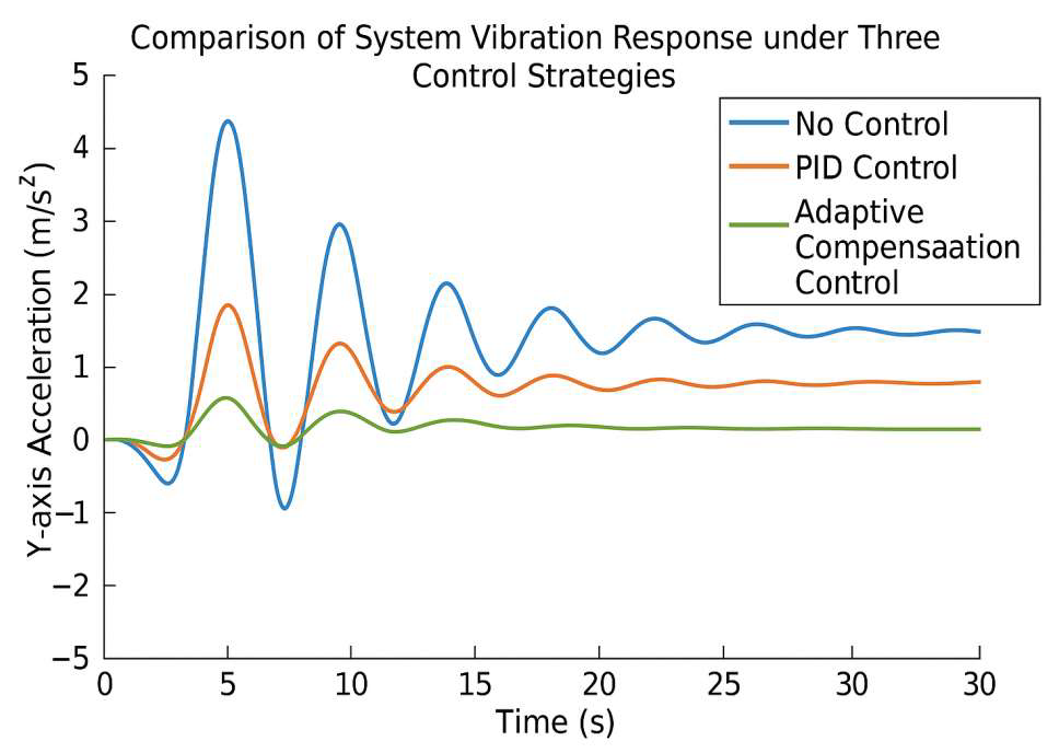
To verify the effectiveness of the proposed adaptive PID and real-time compensation strategy, a comparative simulation is conducted on the ADAMS-MATLAB platform using three modes: no control (open-loop), traditional PID, and the proposed method. Simulation parameters are set as: 300 rpm speed, 5.2 g initial eccentricity, 30 s simulation time, and 1000 Hz sampling rate [10]. Evaluation metrics include vibration amplitude, convergence time, steady-state residuals, and control energy. The primary vibration is along the Y-axis, measured as ay(t), with its RMS value arms as the key index. The integral of control input u(t) is used to assess control effort. Fig. 6 shows vibration responses under the three strategies, highlighting differences in suppression and convergence performance under identical conditions.
Figure 6.
Comparison of system vibration response curves under three control strategies.
5.2. Experimental validation
To further validate the control strategy on a physical platform, dynamic experiments are conducted under three conditions: no control, traditional PID, and adaptive PID with compensation. The initial eccentricity is set to 5.0 g, rotation speed at 300 rpm, and test duration is 40 s. Acceleration signals are collected via PCB accelerometers and recorded in real time using LabVIEW, while Simulink generates control commands sent to the actuators via CAN. Y-axis vibration responses are recorded synchronously, and data from the 10th to 35th second are analyzed to exclude startup transients. Figure 7 shows the Y-direction acceleration curves under the three strategies. The proposed method achieves faster convergence and better vibration suppression, stabilizing the system within 10–20 s, confirming its real-time effectiveness and platform adaptability.
6. Conclusion
This study focuses on the dynamic imbalance problem during the rotation of the CT scanner frame, constructs a multi-body dynamics model and introduces adaptive PID and real-time compensation algorithms, which effectively improves the stability of the system operation and vibration suppression accuracy. Although the control strategy shows strong adaptability in simulation and experiment, its robustness in higher speed and complex working conditions still needs to be further improved, and there is room for optimizing the coupling modeling accuracy between the control system and the structural system. In the future, we can combine the electromechanical cooperative optimization design and high-precision state observation method to expand the application boundary in other rotating medical devices.
References
- Edelmann, J.T.U. S01-01: Multi-body dynamics. Minisymposia 2023, 16, 84. [Google Scholar]
- Cornejo, J.; Sierra, J.E.; Gomez-Gil, F.J.; A Gallego, J.; Biancardi, C.M.; Weitzenfeld, A. Multibody system dynamics for bio-robotic design and simulation based on inching-locomotion caterpillar’s gait: MBD-ILAR method. Bioinspiration Biomimetics 2024, 20, 016021. [Google Scholar] [CrossRef] [PubMed]
- Fan, Y.; Pei, Z.; Wang, C.; Li, M.; Tang, Z.; Liu, Q. A Review of Quadruped Robots: Structure, Control, and Autonomous Motion. Adv. Intell. Syst. 2024, 6. [Google Scholar] [CrossRef]
- Milone, D.; Risitano, G.; Pistone, A.; Crisafulli, D.; Alberti, F. A New Approach for the Tribological and Mechanical Characterization of a Hip Prosthesis Trough a Numerical Model Based on Artificial Intelligence Algorithms and Humanoid Multibody Model. Lubricants 2022, 10, 160. [Google Scholar] [CrossRef]
- Multiscale Modeling to Tackle the Complexity of Load-Bearing Organ and Tissue Regulation[M]. Frontiers Media SA, 2022.
- Zhang, Z.; Xiao, H.; Wang, Y.; Chi, Y.; Nadakatti, M.M. Response analysis and effect evaluation of dynamic stabilization for ballasted track. Constr. Build. Mater. 2023, 403. [Google Scholar] [CrossRef]
- Qiu Y. Modeling Dynamics of Multi-Body Systems via Machine Learning and Non-Markovian Approaches[M]. The University of Wisconsin-Madison, 2024.
- Xie, D.; He, J.; Liu, T.; Liu, C.; Zhao, G.; Chen, L. Establishment and validation the DEM-MBD coupling model of flexible straw-Shajiang black soil-walking mechanism interactions. Comput. Electron. Agric. 2024, 224. [Google Scholar] [CrossRef]
- Shah, M.F.; Jamwal, P.K.; Goecke, R.; Ghayesh, M.H.; Hussain, S. Performance-based design synthesis and analysis of a 6-4 UPS parallel mechanism based virtual biomechanical shoulder robot model. Mech. Based Des. Struct. Mach. 2025, 1–21. [Google Scholar] [CrossRef]
- Guo, J.; Wang, J.; Chen, J.; Ren, G.; Tian, Q.; Guo, C. Multibody dynamics modeling of human mandibular musculoskeletal system and its applications in surgical planning. Multibody Syst. Dyn. 2023, 57, 299–325. [Google Scholar] [CrossRef]
Figure 1.
CT scanner frame structure composition and parts labeling diagram.
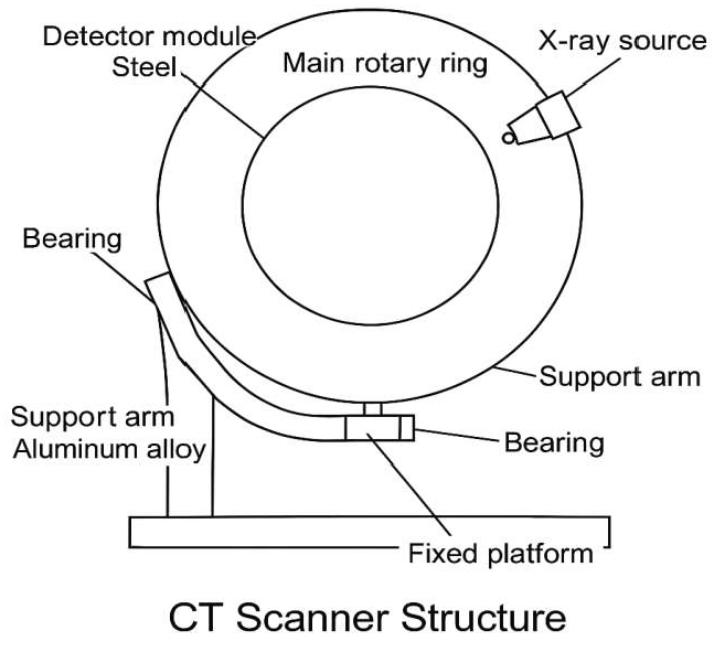
Figure 4.
Block diagram of CT scanner frame dynamic balance control system structure.
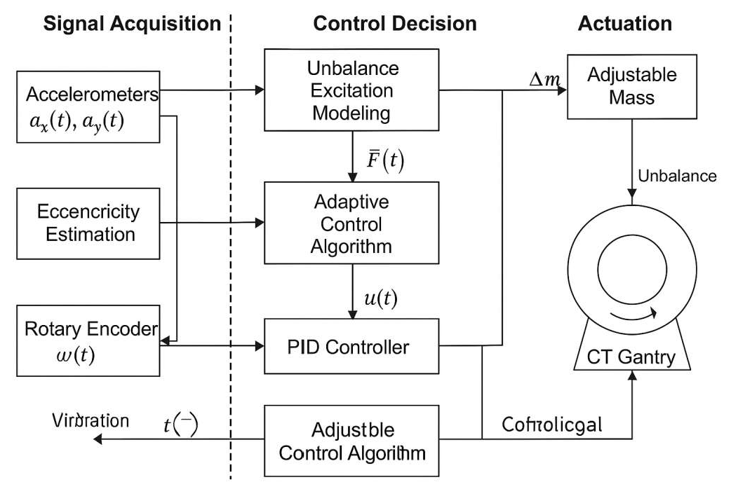
Figure 5.
CT scanning frame experiment platform structure and signal wiring diagram.
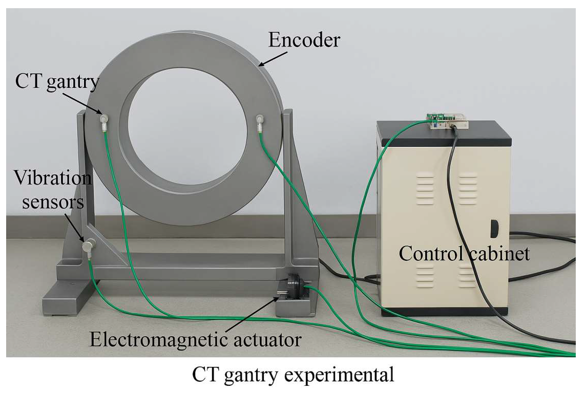
Figure 7.
Comparison of Y-direction acceleration response of experimental platform under different control strategies.
Figure 7.
Comparison of Y-direction acceleration response of experimental platform under different control strategies.
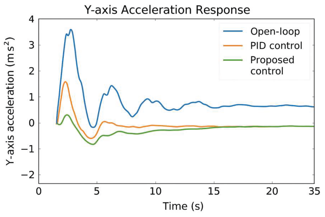

Table 2.
Table of modeling parameters for the CT scanning frame multibody system.
| Rigid Body Number | Part Name | Mass (kg) | Moment of inertia Iz (kg-m²) | Type of sport |
|---|---|---|---|---|
| B1 | primary rotating ring | 35.4 | 4.62 | Flat + Rotation |
| B2 | Detection Module | 18.2 | 1.15 | flatten out (of a tire) |
| B3 | support arm | 22.6 | 2.87 | Flat + Rotation |
Table 3.
Table of unbalanced excitation parameters of the main components of the CT scanning frame.
| Component number | Part Name | Mass deviation Δmi (kg) | Eccentricity ei (mm) | Excitation force amplitude Fi (N,@300rpm) |
|---|---|---|---|---|
| B1 | primary ring of rotation | 0.215 | 5.8 | 20.42 |
| B2 | Detection Module | 0.092 | 4.2 | 6.91 |
| B3 | support arm | 0.163 | 6.5 | 16.53 |
Table 5.
Adaptive PID controller parameter setting and regulation strategy table.
| parameter term | starting value | limit | lower limit | Update period (ms) |
|---|---|---|---|---|
| Kp | 12.5 | 25.0 | 6.0 | 5 |
| Ki | 180.0 | 300.0 | 100.0 | 10 |
| Kd | 0.75 | 2.0 | 0.2 | 5 |
Disclaimer/Publisher’s Note: The statements, opinions and data contained in all publications are solely those of the individual author(s) and contributor(s) and not of MDPI and/or the editor(s). MDPI and/or the editor(s) disclaim responsibility for any injury to people or property resulting from any ideas, methods, instructions or products referred to in the content. |
© 2025 by the authors. Licensee MDPI, Basel, Switzerland. This article is an open access article distributed under the terms and conditions of the Creative Commons Attribution (CC BY) license (http://creativecommons.org/licenses/by/4.0/).
Copyright: This open access article is published under a Creative Commons CC BY 4.0 license, which permit the free download, distribution, and reuse, provided that the author and preprint are cited in any reuse.


