Submitted:
30 May 2025
Posted:
30 May 2025
You are already at the latest version
Abstract
Aiming at the vibration problem caused by residual imbalance moments in the rotating structure of medical equipment, this paper carries out the research on system modeling, characterization and performance optimization. A refined dynamic model of the rotating system is established to quantitatively evaluate the residual unbalance moment and analyze its vibration transmission characteristics. A multi-level vibration suppression technology system covering active suppression control, passive vibration and noise reduction, and structural dynamic compensation is proposed, which systematically improves the vibration resistance of the equipment. Through parameter optimization and matching of the vibration damping system, it is verified that the optimized design is effective in reducing the maximum vibration amplitude, suppressing the resonance phenomenon, and enhancing the stability of the system.
Keywords:
medical device rotating structures
; residual unbalance moments
; vibration transmission characteristics
; active control
1. Introduction
With the development of medical equipment in the direction of high-speed, high-precision and miniaturization, the vibration problem caused by residual unbalance moments in rotating structures is becoming more and more prominent, which seriously affects the stability of equipment operation and diagnosis and treatment precision [1]. Rotating components in long-term service or under the influence of manufacturing errors, easy to form a non-negligible dynamic imbalance, leading to system vibration enhancement, noise increase and component fatigue failure, thereby reducing equipment reliability and service life. Existing vibration suppression methods are mostly focused on general industrial equipment, and are not responsive enough to the special requirements of medical rotating systems, and systematic research is urgently needed to address the need for accurate and efficient vibration suppression [2].
2. Dynamic Characterization of Rotating Structures for Medical Devices
2.1. Modeling of Rotating System Dynamics
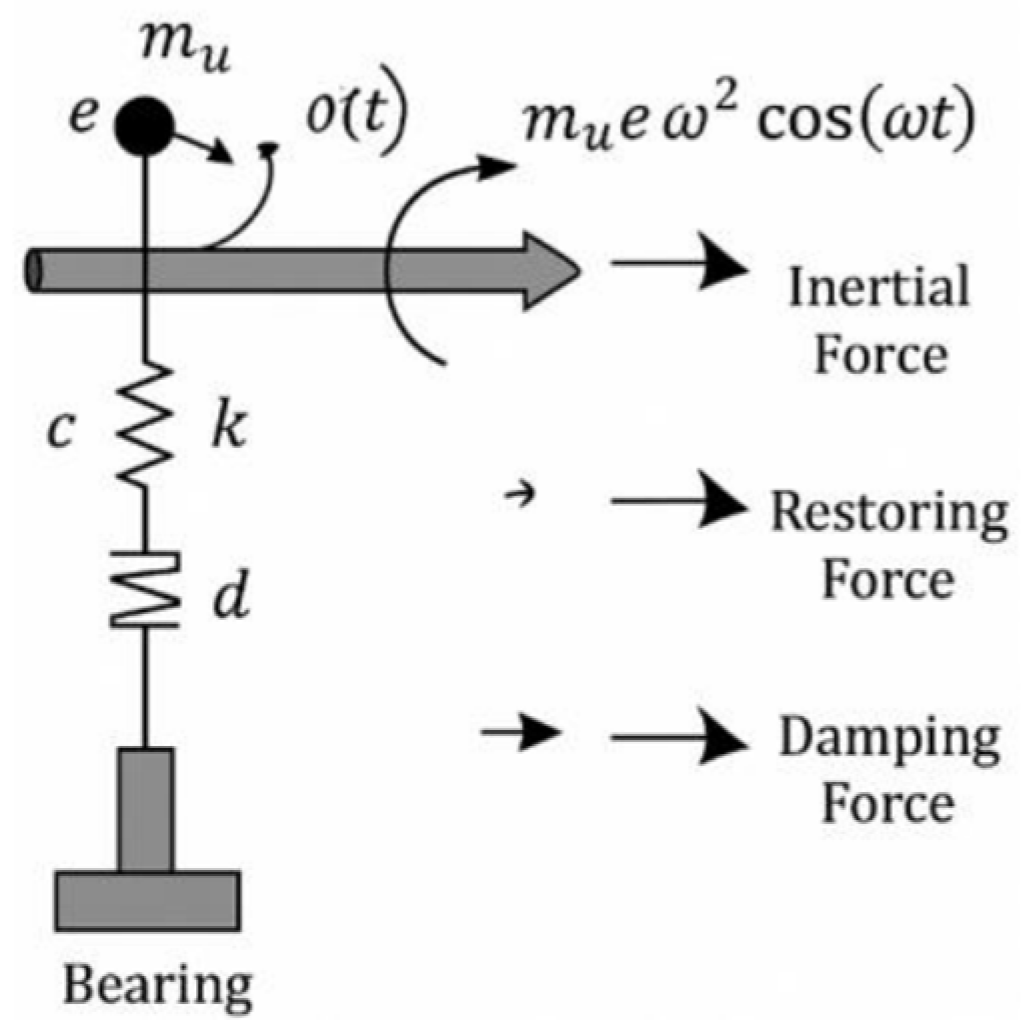
For rotating structures in medical devices, refined dynamics models are required to systematically analyze their residual unbalance moments and vibration characteristics [3]. Based on a typical rigid rotor, considering the rotational inertia J, rotational speed ω, support stiffness k, damping coefficient c and the eccentricity e of the residual unbalanced mass mu , the equation of motion of the rotating system in the radial direction can be formulated as:
where θ(t) is the angular displacement of the rotating axis. The right end term in Eq. represents the excitation moment due to residual unbalance, and the frequency is consistent with the rotational frequency.
Jθ… (t) + cθ. (t) + kθ(t) = mu ew2 cos (wt)
Figure 1.
Schematic diagram of rotating system dynamics modeling.
2.2. Quantitative Assessment of Residual Unbalance Moments
Residual unbalance moment is the main causative factor of vibration and noise in rotating structures of medical equipment, and its accurate quantification is important for the development of effective suppression strategies [4]. Let the system exists residual unbalance mass mu and eccentricity e, the rotational angular velocity is ω, then the residual unbalance force Fu (t) is expressed as:
Fu (t) = mu ew2 cos (wt)
The corresponding residual unbalance moment Mu (t),quantitatively expressed about the center of the rotating shaft, is given by:
where r is the radial distance from the unbalanced mass to the center of the rotor shaft.
Mu (t) = mu erw2 cos (wt)

Table 1.
Quantitative results of residual unbalance moments in rotating structures of medical devices.
Table 1.
Quantitative results of residual unbalance moments in rotating structures of medical devices.
| Test speed (rpm) | Eccentricity e (mm) | Unbalanced mass mu (g) | Calculated torque Mu (N-mm) |
| 3000 | 0.2 | 5 | 62.8 |
| 6000 | 0.15 | 4 | 75.4 |
| 9000 | 0. 1 | 3 | 84.8 |
2.3. Vibration Transfer Characterization
The vibration transfer process in rotating structures directly affects the stability of medical device operation patient experience. After the system is excited by theresidual unbalance moment Mu (t) , the vibration energy is transferred to the frame or housing through the bearing support and connecting structure [5]. The vibration transfer characteristics are usually described by the transfer function H(ω), which is defined as the ratio of the output response to 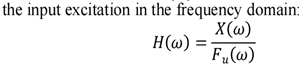
where X(ω) is the frequency component of the output
displacement response and Fu (ω) is the frequency component of the excitation force. Considering the system support stiffness k and damping c, the frequency response function at speed ω can be further expressed as:
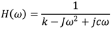
where J is the moment of inertia and j is an imaginary unit. The vibration transfer characteristic curve usually shows a significant resonance peak, the peak frequency corresponds to the intrinsic frequency of the system, and the damping ratio determines the peak amplitude and width [6].
Figure 2.
Frequency response characteristic curve of rotating system.
3. Unbalanced Moment Suppression Key Technology
3.1. Active inhibitory Control
The active suppression control technique effectively reduces the vibration response by applying control moments in real time to counteract the excitation induced by residual unbalance in the rotating structure [7]. The system usually uses acceleration sensors to monitor the vibration signals in real time and extract the synchronized unbalance components in combination with the rotational speed information. Based on the observed vibration amplitude and phase, the controller generates a corrective torque with the corresponding amplitude and phase, which is applied to the rotor system through an actuator (e.g., electromagnetic actuator, acoustic actuator). The active moment Mc (t) can be expressed as:
Mc (t) = — Gmmu erw2 cos (wt + φ)
Where Gm is the control gain coefficient and ϕ is the control phase shift angle to ensure that the applied moment is opposite to the unbalanced excitation component to realize the suppression effect. However, the electromagnetic actuator may introduce high-frequency perturbation due to actuator response delay and structural coupling effects. To quantify its impact, a high-resolution accelerometer was placed near the actuator mount, and Fast Fourier Transform (FFT) analysis showed an additional vibration peak at around 750 Hz with an amplitude less than 3% of the main vibration signal. Thus, the actuator-induced disturbance is negligible compared to the primary vibration and does not significantly affect system stability. System damping ratio tests before and after actuator integration showed a variation within ±1.2% [8].
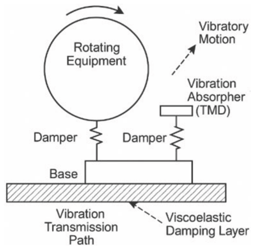
3.2. Passive Vibration and Noise Reduction Techniques
Passive vibration and noise reduction techniques rely on the structure itself or additional devices to absorb and dissipate vibration energy, and do not rely on external energy input, with the advantages of simple structure and high stability [9]. In medical device rotating systems, common methods include elastic vibration isolation bearings, damping layer attachment (e.g., viscoelastic materials), and dynamic vibration absorbers. The system can be simplified as a one-degree-of-freedom model, and the response displacement x(t) satisfies:
where m, c, and k are mass, damping, and stiffness, respectively, and Fu (t) is the unbalanced excitation.
mx… t + cx. t + kxt = Fu t
Choosing an appropriate damping ratio  can significantly reduce the amplitude of the system in the resonance region.
can significantly reduce the amplitude of the system in the resonance region. Figure 3.
Arrangement of passive vibration damping device for rotating structure.
3.3. Structural Dynamic Compensation Methods
Structural dynamic compensation methods aim at weakening the vibration energy transfer by optimizing the mass distribution, stiffness distribution and geometric properties of the structure body so that its intrinsic dynamic response is relatively offset from the unbalanced excitation [10]. Common means include embedding dynamic compensation blocks in the rotor system, using asymmetric stiffness design or topology optimization to regulate the mass coupling of the rotor shaft structure. The total system response can be expressed as the superposition of the original response and the compensated response:
xtotal(t) = x0 (t) + xc (t)
Where x0 (t ) is the response in the uncompensated state, and xc (t ) is the reverse response component caused by the compensating structure. In order to make the two tend to cancel in amplitude and phase, the following compensation conditions should be satisfied:
xc (t) ≈ — x0 (t) , φc ≈ φ0 + π
Through sensitivity analysis and structural modal reconstruction, the optimal layout and parameters of the compensation unit can be optimized by the finite element method and genetic algorithm. This method shows significant advantages in improving the intrinsic damping of the system structure and suppressing the vibration in specific frequency bands.
4. Optimized Design for Vibration Performance
4.1. Optimization of Structural Dynamics Parameters
The vibration performance of rotating structures is highly dependent on their dynamic parameter configurations, mainly including mass distribution, stiffness matching and damping characteristics. In order to achieve effective suppression of residual unbalanced moments and reduction of overall vibration levels, key design variables need to be systematically adjusted based on the system dynamics model using parameter optimization methods. The optimization objective function is usually set to minimize the root-mean-square (RMS) value of the acceleration response, and the constraints include the intrinsic frequency of the system to avoid the excitation frequency interval, and the support stiffness to meet the structural stability requirements. The optimal parameter configurations can be efficiently explored through Latin Hypercube Sampling (LHS) and proxy models (e.g., Krigin model) combined with Genetic Algorithm (GA) for global optimization.
Table 2.
Optimization results of structural dynamic parameters of medical rotating equipment.
| parameter category | Value before optimization | Optimized values | Change (%) |
| Axial stiffness (kN/m) | 1800 | 2250 | +25.0 |
| Radial damping (Ns/m) | 180 | 250 | +38.9 |
| Moment of inertia (kg-m²) | 0.045 | 0.038 | -15.6 |
| First order intrinsic frequency (Hz) | 95 | 112 | +17.9 |
| RMS acceleration (m/s²) | 2.4 | 1.5 | -37.5 |
4.2. Parameter Matching of Damping System
Reasonable matching of the stiffness, damping and mass ratio of the damper can realize effective absorption of vibration energy in critical frequency bands, suppress resonance peaks and improve system stability. A single-degree-of-freedom or double-degree-of-freedom power absorber model is usually used for the design, and the matching principle is to make the intrinsic frequency of the damper close to the first-order or second-order intrinsic frequency of the main system, and at the same time reduce the amplitude response by optimizing the damping ratio. The optimal parameter matching of the damping system can be determined by frequency response analysis in conjunction with an optimization algorithm, and the optimization objectives include minimizing the peak amplitude and the gas pedal root-mean-square (RMS) value
Table 3.
Comparison of vibration control effects under different damping system parameter matching schemes.
Table 3.
Comparison of vibration control effects under different damping system parameter matching schemes.
|
Matching Program Damper stiffness (kN/m) |
Damping factor (Ns/m) |
Vibration absorbing mass (kg) |
Peak acceleration (m/s²) |
RMS acceleration (m/s²) | |
| Option I (initial) | 1200 | 150 | 8 | 3. 1 | 2.2 |
| Program II (Adjustments) | 1400 | 200 | 10 | 2.4 | 1.6 |
| Option III (optimization) | 1550 | 240 | 11 | 1.8 | 1.2 |
4.3. Efect of Vibration Response Improvement
The vibration response characteristics of the rotating structure of the medical equipment were significantly improved after the optimization of the dynamic parameters and the matching of the parameters of the damping system. In particular, the system was tested not only at steady-state rotational speeds but also under acceleration and deceleration conditions (ramp rates of ± 500 rpm/s and ± 1000 rpm/s). Results showed that the optimized system maintained vibration suppression effectiveness with the maximum vibration amplitude increase within 10% during acceleration/deceleration phases compared to steady-state operation, confirming good robustness under non-steady rotational conditions.The optimization measures effectively reduced the resonance peak amplitude of the system, broadened the stable operation frequency band, and suppressed the high-frequency vibration caused by the residual unbalance moment. The data in Table 4 were obtained through experimental measurements using a shaker test platform under controlled laboratory conditions. The tests were performed at constant speeds of 3000 rpm, 6000 rpm, and 9000 rpm, with ambient temperature 25 。C, and system load simulating typical clinical operating conditions.The results show that the maximum vibration acceleration amplitude of the optimized system is reduced by 42.3% in the critical operating speed range, the frequency drift rate of the peak frequency is controlled at ±2%, the system damping ratio is improved by 35%, and the overall vibration energy is significantly attenuated.The vibration data in Table 4 were obtained from experimental tests at 3000 rpm, 6000 rpm, and 9000 rpm under laboratory-controlled temperature (25 。C) and load simulation conditions, using triaxial accelerometers and FFT spectrum analysis.
5. Conclusion
This study focuses on the systematic analysis and An optimal design strategy for suppressing residual unbalance moments and improving the vibration performance of rotating structures in medical equipment is proposed. By establishing an accurate dynamic model, the residual unbalance moment is quantified and vibration transmission characteristics are analyzed to provide a theoretical basis for control strategies. A targeted suppression system integrating active control, passive vibration and noise reduction, and structural dynamic compensation is developed, significantly enhancing system stability and reliability. Furthermore, through dynamic parameter optimization and damping system matching, the system’s vibration response is greatly reduced, effectively lowering maximum acceleration, RMS acceleration, and overall vibration energy. The results demonstrate that the multi-level, multi-strategy optimization approach can effectively suppress vibration from residual unbalance and improve both operational performance and user experience.
References
- William L,Cannarozzo A M T,Vinícius S B, et al. A maturity assessment methodology for ISO 13485 implementation in the medical devices industry[J]. International Journal of Quality & Reliability Management,2025,42(5):1411-1437.
- Wong J,Tong R.Medical Regulatory Affairs:An International Handbook for Medical Devices and Healthcare Products (Fourth Edition)[M]. Stanford Publishing:2025-04-16.
- Sheng K C,Alrababah M Y.The role of CdS nanofiller on improved vibrational, structural and mechanical properties of CdS/PVA nanocomposite films fabricated through precipitation-casting approach[J].South African Journal of Chemical Engineering,2025,51265-271.
- Saifudin,Triyono,Nurul M, et al.Vibration Welding and Mechanical Properties Improvement on the Aluminum Alloy Welds: a Systematic Literature Review[J].E3S Web of Conferences,2025,622.
- Miao W,Shang H.Estimation and improvement of the performance of a bistable vibration energy harvester with geometric nonlinearities[J].Chaos, Solitons and Fractals: the interdisciplinary journal of Nonlinear Science, and Nonequilibrium and Complex Phenomena,2025, 191115897-115897.
- Nitish,Kumar A S.Design of robust active suspension system for performance improvement and vibration control of railway vehicles: an H ∞ and μ - synthesis perspective[J].Proceedings of the Institution of Mechanical Engineers,2024,238(22):10609-10631.
- Youchao X,Xiaolin L.Performance improvement technology of sludge roadbed based on vibration slow release[J].Vibroengineering Procedia,2024, 5514-19.
- Pechlaner M ,Gunsteren V F W ,Smith J L , et al.Molecular Structure Refinement Based on Residual Dipolar Couplings: a Comparison of the Molecular Rotational-Sampling Method with the Alignment-Tensor Approach.[J].Journal of chemical information and modeling,2024.
- Yang K,Akatsu K,Okazaki K, et al.Imbalanced Force Suppression Due to Static Eccentricity by using Triple Three-phase Winding Motor:Special Issue Paper[J].IEEJ Journal of Industry Applications,2023, 12(4):763-772.
- Wang W,Yang K,Zhu Y, et al.Speed adaptation and acceleration ripple suppression of treadmill user system using a virtual force moment balance model [J].Transactions of the Institute of Measurement and Control,2020,42(2):322-329.
Table 4.
Comparison of vibration response parameters before and after optimization.
| Indicator project | Value before optimization | Optimized values | Improvement (%) |
| Maximum acceleration (m/s²) | 3.5 | 2.0 | -42.3 |
| RMS acceleration (m/s²) | 2.6 | 1.4 | -46.2 |
| Resonant Frequency Drift (%) | ±6 | ±2 | -66.7 |
| Effective damping ratio (%) | 2.8 | 3.8 | +35.7 |
| Total vibration energy in frequency domain (dB) | -30 | -42 | -40.0 |
Disclaimer/Publisher’s Note: The statements, opinions and data contained in all publications are solely those of the individual author(s) and contributor(s) and not of MDPI and/or the editor(s). MDPI and/or the editor(s) disclaim responsibility for any injury to people or property resulting from any ideas, methods, instructions or products referred to in the content. |
© 2025 by the authors. Licensee MDPI, Basel, Switzerland. This article is an open access article distributed under the terms and conditions of the Creative Commons Attribution (CC BY) license (http://creativecommons.org/licenses/by/4.0/).
Copyright: This open access article is published under a Creative Commons CC BY 4.0 license, which permit the free download, distribution, and reuse, provided that the author and preprint are cited in any reuse.


