
Submitted:
14 May 2025
Posted:
19 May 2025
You are already at the latest version
Abstract
Internet of Things (IoT) is about networking smart devices to share information, while Cyberphysical Systems (CPS) is about integrating computational intelligence directly into physical processes to enable control and automation. CPS goes beyond connecting devices to include real-time processing and decision-making capabilities. We will call the combined ecosystem the Internet of Cyber-Things (IoCT), to convey a vision where smart devices are not just connected but are also tightly integrated with physical control systems—a network where digital and physical realms work harmoniously. Simulation-based development of a combined Internet of Things (IoCT) and Cyber-Physical Systems (CPS) using DEVS (Discrete Event System Specification) is an approach that leverages simulation techniques to design, analyze, and optimize systems in which smart devices (IoCT) interact closely with real-world control processes (CPS). This methodology allows developers to virtually build, test and implement complex systems within the same formal framework. In this review, we will show that DEVS has the necessary properties, including model expressiveness and development continuity, to serve as an IoCT simulation-based development language. We will illustrate with several examples to show the wide applicability to IoCT systems. We will demonstrate the added value of the System Entity Structure (SES) to enhance expressiveness, scalability, and flexibility in IoCT system design, making it a powerful tool for managing complexity and enabling efficient simulation and deployment. In addition, we will formulate conditions that are necessary and sufficient for IoCT system development and show how DEVS-based model-driven engineering methodology helps to meet them.
Keywords:
Internet of Things
; Cyberphysical Systems
; DEVS
; System Entity Structure
; model-driven engineering methodology
; Simulation
1. Introduction
Internet of Cyber-Things (IoCT) [1] refers to systems designed within the paradigms of Internet of Things (IoT), emphasizing the the connectivity of devices ("Things") with robust, cyber-enabled control over physical processes (CPS).
The combined paradigm recognizes that an internet backbone not only connects devices but can actively manage and control physical systems in real time [1]. The combination suggests the overarching goal of a seamless integration and coordination of smart devices, bolstered by advanced cyber capabilities that control and optimize physical dynamics [1]. In such a network, digital and analog information flows through channels between sensors and effectors under the control of computational intelligence [1,2].
Simulation-based development involves creating virtual models of a system to study its performance, behavior, and potential failure modes under different conditions. By simulating the system, designers can iterate rapidly on design choices, validate functionality, and optimize performance. Through detailed simulation, designers gain insights into how cyber components (software, network protocols) and physical entities (sensors, actuators) interact, ensuring that real-time constraints and performance requirements are met. Such simulation also allows for comprehensive testing under varied environmental conditions and scenarios, mitigating the risk of failure when the system is deployed in the real world. When simulation is employed early in development, the high costs of early-stage physical prototyping can be minimized or even eliminated, reducing the need for expensive physical prototypes with associated development costs and potential downtime.
Simulation-based development addresses the role of communication and control in IoCT by representing interactions such as sensor data transmission, actuator commands, and control logic as streams of discrete events. Simulation supports examining how data flows through the network and how control decisions are made in real time, which is crucial when merging the loosely coupled nature of IoT with the stringent requirements of CPS. By running simulations, developers can subject the system models to various challenges including communication delays, system failures, and unexpected physical process behaviors. These simulations help to identify potential bottlenecks or design flaws, enabling iterative refinements before actual hardware deployment.
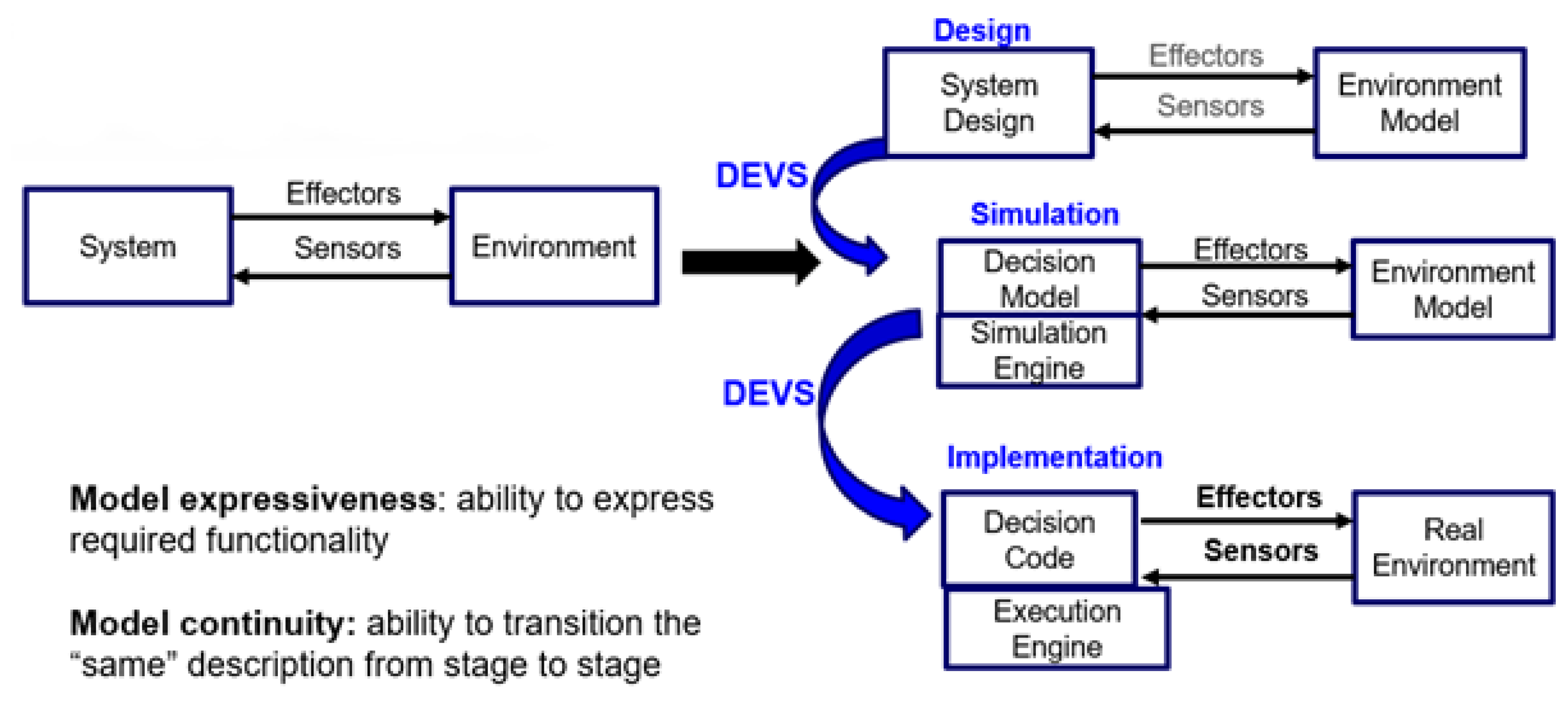
We propose that essential requirements for a language to support the development of IoCT systems are model expressiveness and model continuity for all stages of the process including design, simulation, and implementation (see Figure 1).
Basically, model expressiveness is the ability to express required functionality in a form that can be easily coded, simulated, and verified. Included in expressiveness is the ability to support construction of simulation models that combine discrete event logic with continuous system dynamics which is particularly useful in CPS where physical processes involve continuous variables (e.g., temperature, motion). Expressiveness also includes the ability to incrementally add or modify model components, which is especially useful as IoCT technologies continue to evolve.
Likewise, model continuity refers to the ability to transition the "same" description from stage to stage in the development process, where by "same", we mean that little or no modification is needed in such transitions. Included in continuity is capturing and handling the stringent timing requirements typical of IoCT applications, ensuring that the simulated responses closely mimic real-world behaviors.
The Discrete Event System Specification (DEVS) formalism [3] is a formal modeling and simulation framework that allows systems to be described as a set of discrete events. It offers a modular and hierarchical approach, where individual components (atomic models) can be composed to form more complex structures (coupled models). This makes it ideal for modeling both the asynchronous events of IoT devices and the real-time processes of CPS. DEVS enables component-based, hierarchical modular construction, and dynamic changes in structure to support intelligent, adaptive, and autonomous behavior characteristic of IoCT systems [4,5,6]. DEVS Atomic Models enable each IoT device or CPS component to be modeled as an atomic (independent) entity with defined states and transitions triggered by discrete events. DEVS coupling concepts connect atomic components to form coupled models that represent larger subsystems or the entire system. This hierarchy helps manage complexity and supports system evolution.
In this paper, we will show that DEVS has the necessary model expressiveness and continuity properties to serve as an IoCT Design language. We will illustrate with several examples to show wide applicability. We will demonstrate the added value of the System Entity Structure (SES) to enhance expressiveness, scalability, and flexibility in IoCT system design, making it a powerful tool for managing complexity and enabling efficient simulation and deployment.
Figure 1 illustrates the stages and the requirements for an IoCT Design Language. On the left side of Figure 1 we conceptualize an IoCT system as interacting with its environment through sensors and effectors (also called actuators), and on the right side, three basic stages of the development of such a system are shown as Design, Simulation, and Implementation. In the design stage, the focus is on system architecture, often using high-level design tools [7], with the environment and the sensor/effector interaction minimally represented. Model continuity allows transferring the designed model to be evaluated in the simulation stage and deployed in the implementation stage with minimal changes. Currently, an IoCT design language that supports these requirements is lacking [8]. On the other hand, DEVS model expressiveness is manifested in its support of hierarchical and modular model construction. These characteristics enable the implementation and verification of smaller models, which can then be coupled to form a complete model. In this process, a family of models emerges in which the models can be reused and integrated with multiple other models. Moreover, DEVS allows for the simulation of these models alongside in the context of previously constructed models that can apply to both discrete-event and continuous systems [9]. Furthermore, DEVS supports model continuity in which only the simulator needs to be changed to run from abstract time to real-time [10,11] while the model remains substantially the same.
Figure 1.
Stages and the requirements for an IoCT Design Language. The DEVS formalism provides the model expressiveness needed for IoCT functional design and supports the model continuity needed to transition from stage to stage.
Figure 1.
Stages and the requirements for an IoCT Design Language. The DEVS formalism provides the model expressiveness needed for IoCT functional design and supports the model continuity needed to transition from stage to stage.
The remainder of this paper is organized as follows. Section 3 provides a review of the DEVS formalism and the SES, which serve as foundational frameworks for the modeling and simulation (M&S) of complex systems. Section 3 presents requirements for IoCT design and development and summarizes how DEVS serves as a language to help users address these requirements.
Section 4 presents a series of illustrative examples demonstrating the application of DEVS in designing IoCT systems. These examples include: home automation, the CAIDE architecture, the Actuation Conflict Management (ACM) framework, and swarm-based systems. Section 5 offers a discussion on how the presented examples highlight the expressiveness of DEVS for capturing dynamic and complex behaviors and its continuity in seamlessly transitioning simulation models to real-world implementations. It also compares these features with those of other widely used formalisms.
Finally, Section 6 concludes the paper by summarizing the key findings and discussing limitations of DEVS-based IoCT system design. It then discusses how model-driven engineering can help address such limitations. Finally, we outline future directions for further leveraging DEVS in IoCT system design.
2. Background in DEVS and SES
DEVS Atomic and Coupled Models specify Mathematical Systems [12], one of the earliest forms of general system specification that combined both the automaton formalism of computer science and the dynamic systems models of control theory [13]. DEVS Atomic model specify the dynamic input/output and state behavior of atomic components (elements that are not further decomposed in the model).
DEVS Coupled models include components and their couplings - connections from output ports of components to input ports of other components. As illustrated in Figure 2, component models can themselves be coupled models (as well as atomic models) leading to hierarchical structures. Closure under coupling of DEVS models is an important theorem that justifies the confidence in managing the complexity of hierarchical models. The theorem states that the resultant of coupling well-defined DEVS models is itself a well-defined DEVS model, i.e, is equivalent in its input/output behavior as a DEVS atomic model [3]. As we will show, such Hierarchical Modular Composition supports the model construction needed for development of IoCT systems.
The System Entity Structure (SES) is a declarative knowledge representation scheme that characterizes the structure of a family of models in terms of decompositions, component taxonomies, and coupling specifications. Formalized by a set of axioms [11], the SES is used to define and construct hierarchical modular DEVS models. As an ontology for M&S, it concentrates a relatively few basic relations as follows:
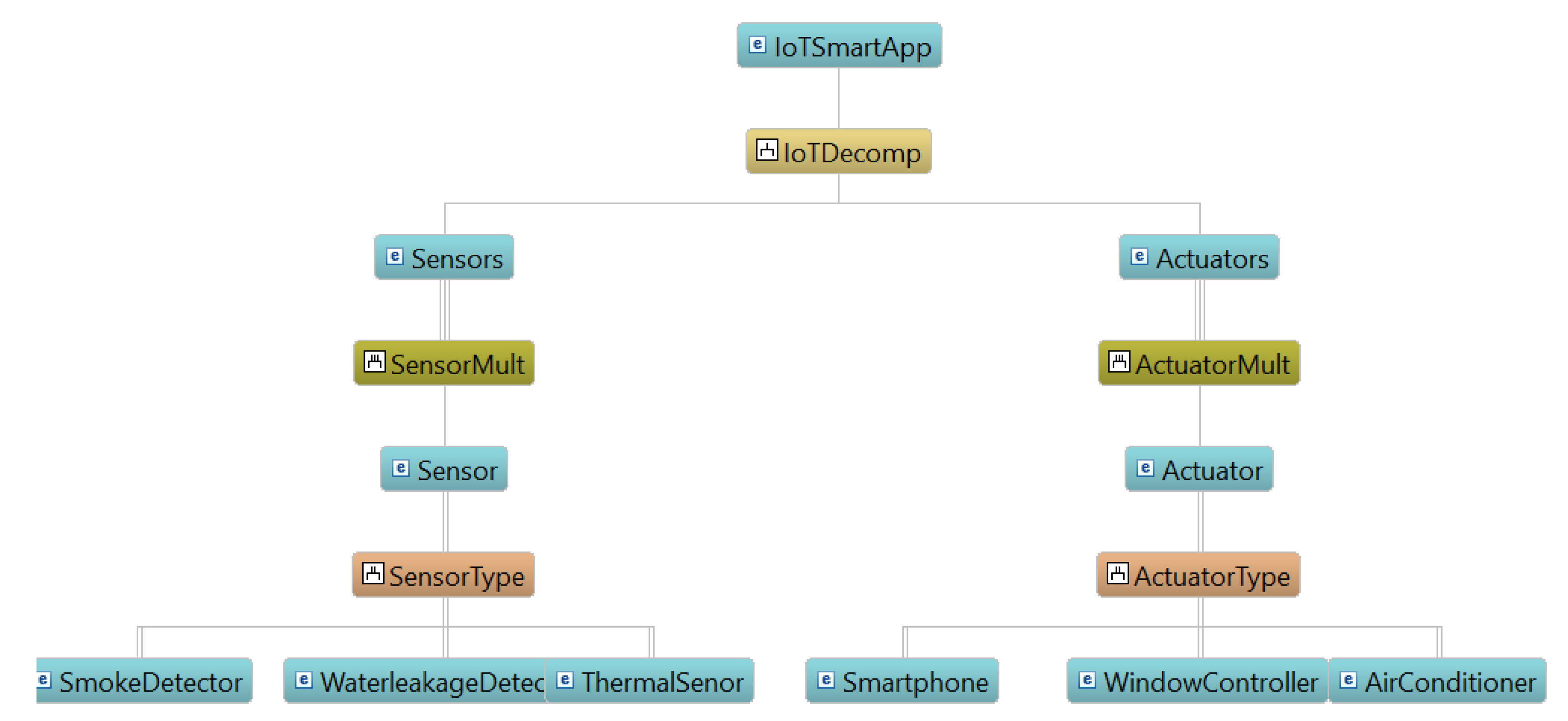
- Aspect expresses a way of decomposing a system into components and is relation between the parent and the children. For instance, IoCTSmartApp in Figure 3 is an entity composed of Sensors and Actuators. Sensors and Actuators are each represented as components (called multi-entities) that are decomposed into one or more Sensor and Actuator, respectively. An aspect holds the coupling relations that will connect the components (children) to create a coupled model for the parent. An entity that has no aspects (decompositions) is the smallest indivisible element and is represented by an atomic DEVS model.
- Specialization expresses the variants that a component can assume within a decomposition. Smoke detector, WaterLeakageDetection or ThermalSensor can replace any of the Sensors and Smartphone, WindowController or AirConditioner can replace any of the Actuators in Figure 3.
The corresponding constrained natural language of the SES description depicted in Figure 3 appears as follows:
From the IoCTDecomp perspective, IoCTSmartApp is made of Sensors and Actuators!
From the SensorMult perspective, Sensors is made of more than one Sensor!
From the ActuatorMult perspective, Actuators is made of more than one Actuator!
Sensor can be SmokeDetector,WaterleakageDetection,or ThermalSenor in SensorType!
Actuator can be Smartphone, WindowController, or AirConditioner in ActuatorType!
Figure 3.
IoCT smart App SES design. Sensors and Actuators are defined as specialization. A sensor entity can be smoke detector or thermal sensor. A actuator can be smartphone or air conditioner.
Figure 3.
IoCT smart App SES design. Sensors and Actuators are defined as specialization. A sensor entity can be smoke detector or thermal sensor. A actuator can be smartphone or air conditioner.
The SES specifies hierarchical coupled models and makes it easier to create them. Indeed, tools exist that help users define SES’s in a constrained form of natural language as well interfaces to prune such models [11]. A specific model is chosen from the SES family of models by selecting from the available choices in a process called pruning. This results in several Pruned Entity Structures (PES), which can then be automatically converted to simulatable DEVS models, thus enabling comparison of alternative architectures [14].
Two other properties of DEVS are applicable to IoCT system design and will be expanded on later:
- DEVS Universality: DEVS models can represent a wide variety of system types including continuous, discrete, finite state, etc. [15]. For instance, when addressing actuation and other service access conflicts in IoCT systems, the rules managing such conflicts are typically specified using particular formalisms. For example, ECA (Event-Condition-Action) rules are widely used for high level specification of controllers in Cyber-Physical Systems and smart environments composed of devices equipped with sensors and actuators. Due to the DEVS universality these description formalisms can be expressed in DEVS models and integrated with other components in a composition hierarchy.
- Dynamic Structure DEVS: a type of DEVS model that can change its own structure while running [16,17]. The ability to change a model’s structure during its simulation is highly interesting in the IoCT domain, where a system can update the list of available devices (sensors or actuators) upon discovering a new context.
3. Requirements for IoCT Design and Development
The identified traits of the DEVS formalism—modularity, event-driven behavior, concurrency, adaptability, scalability, and model continuity—are essential and sufficient for dealing with the complexities of IoCT systems design and development. IoCT systems are inherently heterogeneous, with diverse devices and components that must interact seamlessly. IoCT systems are characterized by several critical requirements:
- Heterogeneity: IoCT systems typically comprise a diverse array of devices, sensors, and actuators, each with distinct communication protocols, data formats, and computational capabilities. An effective modeling formalism must accommodate this heterogeneity and enable seamless interaction between these diverse components.
- Real-Time and Event-Driven Behavior: Many IoCT applications require real-time processing of sensor data, with decision-making based on specific events. For example, a smart thermostat must respond immediately to temperature fluctuations, while a smart city traffic management system must process sensor inputs in real time to optimize traffic flow.
- Concurrency and Synchronization: The dynamic and distributed nature of IoCT systems often necessitates the concurrent operation of multiple devices or subsystems. These devices must interact and synchronize effectively to ensure that the system operates cohesively, without conflicts or performance degradation.
- Adaptability: IoCT systems must be able to adapt to changing environmental conditions, such as the failure of components, the introduction of new devices, or network disruptions. A modeling approach must therefore support flexible system structures capable of responding to such dynamic conditions.
- Scalability: As IoCT systems grow in size and complexity, the ability to scale the system without introducing instability or performance issues becomes critical. A modeling formalism must support scalable architectures that can accommodate the addition of new components or the expansion of existing ones.
- Model-to-Execution Continuity: An IoCT system must transition smoothly from the design phase to the simulation and execution phases. This requires that the behavior modeled during the design phase is accurately reflected in the real-world execution of the system.
DEVS’s modular and hierarchical approach addresses this heterogeneity by enabling the design of complex systems as compositions of simpler, reusable models. Furthermore, IoCT systems often require real-time responses to sensor data, and DEVS’s event-driven nature allows it to model the time-based behaviors that are critical for such applications. The ability of DEVS to handle concurrent events and synchronize multiple interacting processes makes it ideal for modeling the distributed, concurrent nature of IoCT systems, where multiple devices must operate in parallel and remain synchronized. Additionally, IoCT systems must be adaptive to changing conditions, such as device failures or network disruptions, and DEVS supports dynamic model structures that allow for this flexibility. DEVS also facilitates scalability by allowing models to grow incrementally, an important feature for large-scale IoCT systems. Finally, DEVS’s model continuity ensures that the system’s behavior remains consistent throughout the development lifecycle, from design to simulation and real-world execution. This continuity is crucial for ensuring that IoCT systems perform as intended when deployed.
Secondary studies on IoCT systems highlight these same traits as essential, reinforcing that DEVS’s modularity, real-time event handling, concurrency management, adaptability, scalability, and smooth transition across stages are not only sufficient but minimal for modeling IoCT systems effectively. While other formalisms, such as state machines, Petri nets, and UML, may address some aspects of IoCT design, they lack the comprehensive support for concurrency, event-driven behavior, and model continuity that DEVS offers. Thus, DEVS provides a robust and minimal set of traits that make it an ideal candidate for IoCT system design and simulation.
4. DEVS Design Principles for IoCT Systems: Practical Examples
This section is dedicated to presenting several examples highlighting the enhanced expressiveness and continuity offered by DEVS in the field of IoCT systems.
4.1. DEVS Architecture for Home Automation
Faizel and Wainer [9] provide a DEVS specification of a home automation architecture, validated through a case study integrating multiple sensors and actuators. They developed DEVS atomic models for the different functional aspects that are required such as sensor polling, data transmission, and data-sharing algorithms, which were then combined into a complete coupled model for execution on devices. A communication network of nodes was designed as a next level coupled model to integrate the device component models. DEVS-based simulations showed the desired behavior, which was to effectively combine sensor readings and exchanged messages to agree on common values. A home automation application demonstrated the practical use of their approach. The application of DEVS model continuity was manifested in their hardware construction. Using Cadmium version 2, a C++ implementation of DEVS, the C++ classes employed for simulation were flashed (deployed) on micro-controller firmware with only slight modifications in code. One exception was that the message broker model was replaced with a commercial equivalent. Details are described in [9].
In [18], the authors demonstrate the suitability of the DEVS formalism for modeling synchronous automata and verifying execution strategies in the context of IoCT system design. They validate their approach using a pedagogical case study: the development of an application to control room lighting. In this work, the behavior of a DEVS model is represented as specifications of a finite state automaton. However, these DEVS specifications encapsulate both the state automaton and the execution machine. The key advantage of using DEVS lies in its flexibility to define multiple strategies through distinct DEVS model specifications.
The traditional IoCT system design process typically involves: (i) defining the behavior of IoCT components in a library (ii) designing the coupling between components in the library and (iii) executing the resulting coupling. If errors are detected, the designer must redefine component behaviors, particularly those of the execution machine, to handle time conflicts within the ambient system.
In [18], the authors proposed an alternative approach based on DEVS M&S. Instead of waiting until the implementation phase to identify potential conflicts, they introduced an initial phase where the behavior of IoCT components and execution machines is modeled and simulated using DEVS. Once the simulations yield successful results, the designer can confidently implement the system behavior within an IoCT framework. We will also discuss the advantages of DEVS in managing access conflicts in IoCT systems in Section 4.3.
We review how the features of this application illuminate DEVS mode expressiveness and continuity:
-
Model expressiveness:
- –
- Employs hierarchical, modular construction to achieve incrementally verifiable functionality
- –
- Interacts with Sensors and Actuators in a dynamic environment
-
Model continuity:
- –
- DEVS Simulation engine was expressed in programming language (Cadmum V2, Python) for development
- –
- DEVS models were converted to firmware for real-time execution
4.2. DEVS IoCT System: Real-time Monitoring, Management, Forecasting
Developed using the DEVS formalism, the Cloud-Based Analysis and Integration for Data Efficiency (CAIDE) framework has been successfully applied to Solar Irradiance Sensor Farms [19]. The system’s design leverages DEVS, Model-Based Systems Engineering (MBSE) [20], and an IoT infrastructure to deploy and analyze solar plants in dynamic environments. In addition to managing multiple sensor farms simultaneously, the framework continuously enhances predictive models in real time by dynamically adapting and retraining them to ensure forecasts remain accurate and up-to-date.
As illustrated in Figure 4, the system was developed as a hierarchical DEVS coupled model, featuring two primary components: Farms and cloud-based training with big data services. Each Farm comprises atomic models that perform data processing, interface with solar sensors, and coordinate through a central Fog server. The DEVS architecture allows these components to run in sequential, parallel, or distributed configurations, ensuring scalability. The working system was demonstrated in a complex scenario where multiple solar irradiance sensor farms were linked to a centralized management system, highlighting its significant implications for solar plant deployment and the future of renewable energy technologies.
As above, we review how the features of this application illuminate DEVS mode expressiveness and continuity:
-
Model expressiveness:
- –
- DEVS supports expression of the CAIDE architecture which is layered with sensor, Fog, and cloud layers, consistent with IoCT Layered Architecture.
- –
- DEVS atomic models express the required temporal interaction with solar sensors.
- –
- DEVS modularity provides the flexible basis to support the variable functionality required for AI/ML analysis and retraining.
-
Model continuity:
- –
- The DEVS Simulation engine was employed in Python for development.
- –
- A DEVS real-time execution engine continues to implement essentially the same model that resulted from the initial design.
4.3. Conflict Management in IoCT System DevsOps
In managing IoCT conflicts, rigorous validation is essential to detect issues by analyzing both the events generated by smart applications and the resulting actions on shared actuators. As these applications increasingly control common IoCT devices—especially actuators that produce tangible physical effects—the risk of actuation conflicts grows. These conflicts manifest either directly, when multiple applications vie for the same actuator, or indirectly, when applications influence shared physical properties.
To mitigate these challenges, actuation conflicts must be addressed during the design phase, rather than relying on end users to resolve them. The goal is to implement Actuation Conflict Management (ACM) mechanisms that proactively identify and resolve both direct and indirect conflicts early in the system’s lifecycle (see Figure 5). Validation plays a critical role in this process by simulating IoCT application events and actuator responses, ensuring that the ACM specifications remain robust and effective in real-world scenarios.
This approach work builds upon the M&S approach outlined in recent research [21], proposing a method that integrates M&S into the design of IoCT systems (Figure 5). The methodology leverages the DEVS formalism within the DEVSimPy multi-platform framework [22,23], facilitating robust and flexible system Design. DEVSimPy is an advanced wxPython cross-platform General User Interface for the M&S of systems based on the DEVS formalism. With DEVSimPy, a user can construct a DEVS model for a system by interconnecting atomic and coupled models instantiated from libraries.
Figure 5.
DEVS M&S inside the custom ACM Design process with its three levels: The Logical ACM Design, Model validation and Model Deployment.
Figure 5.
DEVS M&S inside the custom ACM Design process with its three levels: The Logical ACM Design, Model validation and Model Deployment.
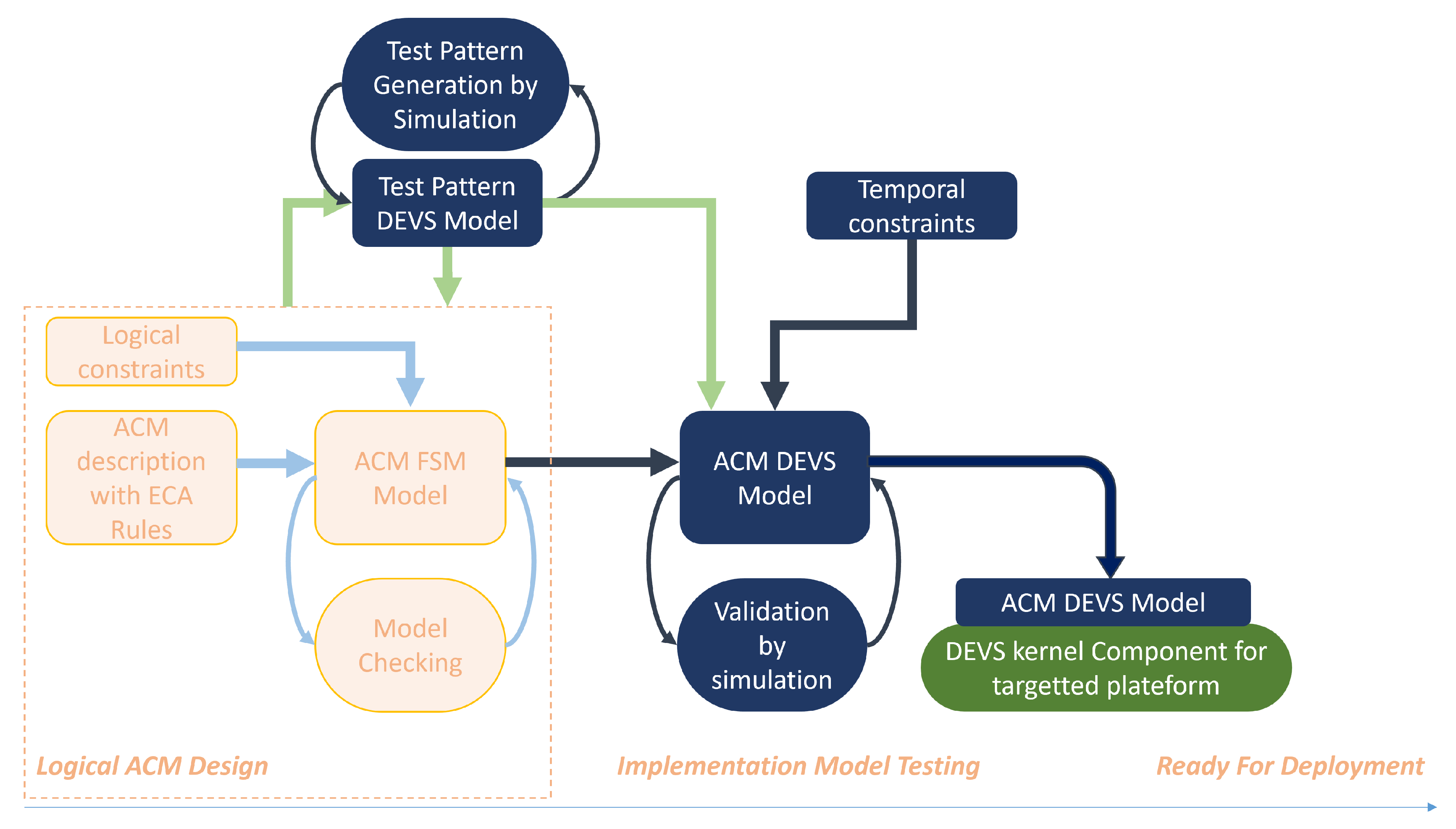
Figure 5 shows the custom ACM Design process that include the following levels:
Figure 5 illustrates a custom ACM design process organized into three main levels:
- Model Validation: This level assesses the impact of conflict resolution on the environment through DEVS simulation. The DEVS ACM model incorporates temporal properties (for example, event delays and state durations) derived from the ACM FSM, ensuring that the temporal behavior of the system is accurately captured.
- Model Deployment At this level, the temporal properties of custom DEVS ACMs are formally verified using various asynchronous execution machine strategies associated with the ACM FSM. DEVS formalism is employed to simulate different implementation approaches, which allows for experimentation with various hardware platforms that have unique asynchronous timing specifications. Moreover, different middleware/EDGE solutions (e.g., node-red [26] and ThingML [27]) can be explored through the automatic implementation of the DEVS simulation kernel tailored to the target middleware.
The approach described above integrates an innovative Actuation Conflict Management (ACM) mechanism that identifies and resolves conflicts stemming from spatial and temporal competition among application flows. In IoCT systems, such conflicts occur when safety properties—whether related to actuators or the environment—are violated. For example, conflicts can emerge when multiple application flows attempt to control the same actuator, thereby compromising one of its features. These conflicts are classified as direct (see Figure 6(a)) when they target a single device, or indirect (see Figure 6(b)) when application flows affect environmental properties inconsistently.
This simulation-based approach intercepts all interactions between application flows (actions) and IoCT devices (actuators) to detect potential direct and indirect conflicts. It validates resolution strategies implemented by a dedicated ACM component (Figure 6(c)).
DEVS models were utilized at an early stage of the ACM Design process, enabling simulation-based validation of the ACM mechanism prior to deployment in physical environments. The results demonstrate the expressiveness of the DEVS formalism in specifying and validating the ACM component, ensuring its seamless integration and functionality within simulated physical environments.
The ACM coupled DEVS model consists of two atomic models: a DEVS Synchronizer, which receives events from application flows and drives the evolution of the Logical Behavior based on the inputs it transmits (Figure 7).
Designers leverage a Logical Behavior model—typically represented as a Finite State Machine (FSM)—to specify conflict resolution rules through defined state transitions and output functions. An execution engine triggers these functions based on incoming inputs, producing the corresponding outputs. Although model checking is effective at validating the logical correctness of the FSM, it does not address issues related to synchronization and timing.
A robust synchronization policy is crucial to maintaining the Logical Behavior’s desired properties. The Synchronizer DEVS model manages input events from IoCT application flows by synchronizing and serializing them according to a pre-defined strategy. This strategy might involve various alternatives such as waiting for all inputs before triggering outputs, sending inputs immediately, or following specific time intervals.
Figure 8) illustrates an example of modeling a custom Actuation Conflict Management (ACM) system in a smart home environment using DEVSimPy, with a focus on conflict detection in IoCT-based smart homes. In this scenario, 216 application flows control 37 actuators—including windows, air conditioners, and lights. Conflicts occur when multiple applications attempt to manage the same actuator; for example, applications 14 and 134 simultaneously controlling the TV. In total, there are 3124 direct conflicts and 673 indirect conflicts. The custom ACM component detects and resolves both types—addressing direct conflicts (such as conflicting TV commands) as well as indirect conflicts (like ambient noise interference between the speaker and TV)—thereby validating the ACM rules.
Due to DEVS model continuity, the DEVS simulation engine was successfully mapped to middleware solutions such as Node-RED and ThingML, enabling straightforward integration with IoCT infrastructures. The objective is to support the orchestration and deployment of IoCT systems whose software components can be deployed over IoCT, edge, and cloud infrastructures. The ACM simulation model can be part of the chosen deployment solution, as the DEVS abstract simulator is portable across any platform [10,18].
Thanks to the DEVS formalism, the approach supports deployment across diverse hardware platforms with varying timing characteristics, underscoring its adaptability and portability. By leveraging the DEVS formalism within the DEVSimPy framework, this work effectively bridges the gap between simulation and practical IoCT implementations—ensuring that validation performed during the design phase translates seamlessly into real-world applications.
Another application where sensor access conflicts arise is smart parking. Smart parking systems optimize the use of parking spaces by integrating driver behavior and sensor data. A major challenge in this field is creating a robust model that can manage cumulative parking conflicts—situations where multiple drivers vie for available parking in a dynamic environment that depends on both user behavior and real-time sensor input. With modern sensor networks, parking spaces can be equipped with sensors that monitor availability in real time. In [28], the authors propose a DEVS-based Modeling and Simulation approach that develops conflict management strategies using estimated travel times to desired locations within an area. DEVS is favored for this application because (i) its explicit inclusion of elapsed time as an essential state variable and the associated time-advance function provides an effective framework for managing time advances in both simulation and real-time scenarios, and (ii) its hierarchical, modular structure supports the construction of conflict models for individual drivers that can be reused in difference scenarios.
Figure 9 depicts the DEVSimPy simulation model for the smart parking system. The simulation starts with the Space atomic models—representing sensors—that are grouped together into a Zone coupled model. Next, the UserLink atomic model aggregates data from these sensors and transmits it to the drivers. The User model then filters and processes the available parking spaces based on specific criteria, passing the pertinent information to the Travel model. The Travel model evaluates this data according to various decision policies and selects an appropriate parking space. Finally, this decision is forwarded to the AccessConflictManagement model, which resolves conflicts between users by applying multiple algorithms to effectively manage competition.
Thanks to DEVS model continuity, the "space" models can be directly linked to an API that delivers real-time sensor data from an operational parking lot. By incorporating user authentication and switching the DEVS simulation kernel to real-time mode, this model becomes suitable for mobile application deployment. In this configuration, the mobile app enables city drivers to locate available parking spaces and occupy them. In fact, this DEVS-based simulation model was deployed within a mobile application—as illustrated in Figure 10—for the city of Bastia in Corsica, France.
To summarize, the features of this application that illuminate DEVS model expressiveness and continuity are:
- Model expressiveness: DEVS ability to express concurrent multiple streams of temporal events enabled simulation-based validation of the actuator coordination mechanism prior to its deployment ensuring its seamless integration and functionality within simulated physical environments.
-
Model continuity:
- –
- The DEVS simulation engine can be mapped to middleware implementations enabling straightforward integration with IoCT infrastructures.
- –
- DEVS supports deployment across diverse hardware platforms with varying timing characteristics, underscoring its adaptability and portability.
- –
- DEVS bridges the gap between simulation and practical IoCT implementation, enabling design-phase validation to be translated effectively to real-world applications.
4.4. DEVS IoCT Development: Dynamic Structure for Adaptive Unmanned Swarm Systems
In [17] Zhang et al. emphasized the model expressiveness capability of DEVS, especially its dynamic structure feature, in application to M&S of unmanned swarm systems (USS). Such systems have broad applicability to a variety of domains including military, agriculture, aerospace, etc. Arguing that traditional modeling methods cannot effectively describe the dynamics of USS, they show how to apply DEVS to design, simulate, and implement such IoCT systems. The article shows how DEVS enables description of the unmanned component platforms from both behavioral and structural perspectives. In the former, DEVS atomic components model the microscopic behaviors; in the latter, DEVS coupling relationships describe the collaborative structure between unmanned platforms.
Particularly, Figure 11 illustrates how swarm growth and self-optimization for surveillance by USS is supported by dynamic structure DEVS. The capability to dynamically add and delete sub-models and input and output ports, and to change port connection relationships enables such systems to make structural adjustments in response to environmental changes. They perform such adaptation in accordance with given goals and structure change rules during simulation operation. A DEVS-based synchronization mechanism supports implementation of coordinated actions and changes in structure as required for adaptive behavior.
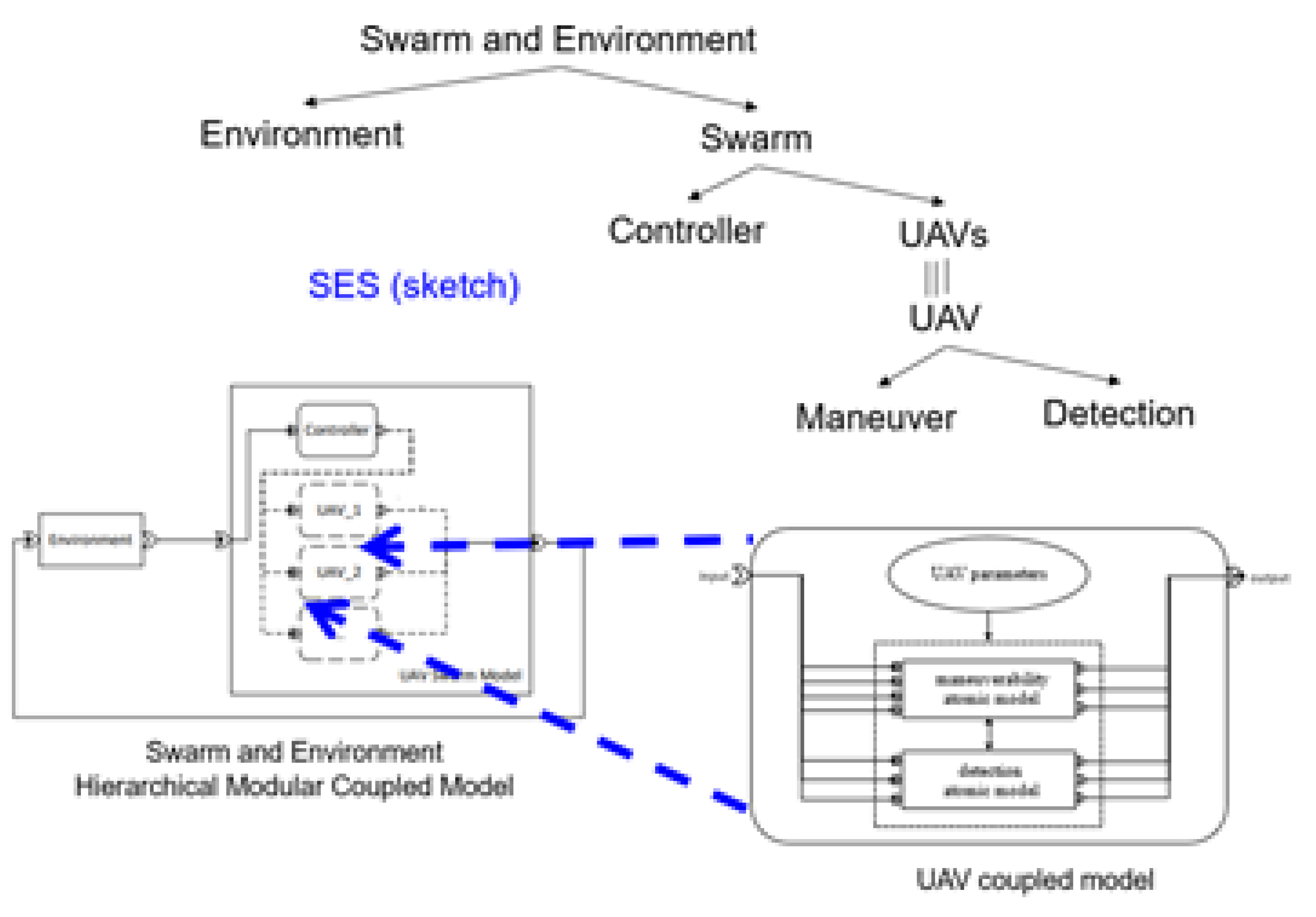
The hierarchical, modular structure of the USS and its environment is sketched in Figure 12 using the SES on top and the block diagram form at the bottom. The Swarm is decomposed into a Controller and Unmanned Autonomous Vehicles (UAVs), each of which are coupled models containing maneuverability and terrain feature detection atomic models. The USS implements adaptive reconnaissance in the sense that UAVs adaptively adjust their positions in the area under surveillance, or exit the mission, following rules such as:
- Deploy a UAV when an area is not being surveilled.
- If a UAV sustains damage exceeding 50 per cent, it must be withdrawn from the mission.
- When a UAV experiences interference, it should exit the interference zone.
- In cases where UAV reconnaissance areas overlap, the UAV with greater damage must vacate the area.
Figure 12.
Hierarchical, modular structure of an unmanned swarm system and its environment is described in the SES (top of figure) and depicted by the hierarchical coupled model (figure bottom). Figure copied and modified with permission.
Figure 12.
Hierarchical, modular structure of an unmanned swarm system and its environment is described in the SES (top of figure) and depicted by the hierarchical coupled model (figure bottom). Figure copied and modified with permission.
Such rules are implemented in the model using the dynamic structure capability of DEVS. Further, the temporal properties of DEVS are well suited to model the synchronization mechanism. The latter is necessary because UAVs can take different amounts of time to finish their assigned tasks due to the heterogeneity of rule application and environmental effects such as damage and interference. Synchronization is implemented by having the controller wait for all UAVs to report that they have completed the preceding task, before issuing the order to proceed to the next task.
Figure 13 leverages the SES to express how synchronization can be implemented in a decentralized manner as opposed to the centralized one just discussed. In the former, the central controller is absent and its functionality is implemented by the individual UAVs. While DEVS expresses the synchronization behavior required in either case, the SES expresses the alternative implementations employing different aspects (decomposition sub-trees) for the centralized and decentralized alternatives, respectively. Figure 14 illustrates such an SES description.
The first line in the fragment of Figure 14 defines an aspect called topLevel that decomposes the overall model SwarmNEnvironment into UAVSwarm and Environment components. Subsequent lines for this aspect declare coupling relations that state how output ports of sender components connect to input ports of receiver components. The yellow and green highlighted lines define two different aspects for decomposing the UAVSwarm component corresponding to those shown in color in Figure 13, respectively. In these lines coupling relations express connections from a coupled model input port to one more of its components input ports (called External Input Coupling) as well as conversely, from component output ports to output ports of the parent coupled model (called External Output Coupling),
4.5. Integration of Cyber Components with IoT devices in IoCT Systems
While IoT design focuses on communication and control of sensors and effectors, CPS design emphasizes the interaction between digital and physical components. As indicated above, applications become more demanding, the two thrusts are converging toward a more complete methodology, called Internet of Cyber-Things (IOCT) that combines their capabilities [29].
Figure 15 presents an architecture that harnesses the DEVS formalism to define the building blocks for both computational and control-theoretic functionalities essential to intelligent CPS design [30]. A related implementation, discussed in [31], exploits DEVS model continuity to efficiently develop embedded controllers for robotic systems. This same continuity supports the design, simulation, and implementation of similar concepts for USS systems as well.
In this use case, the features that illuminate DEVS model expressiveness and continuity are:
-
Model expressiveness:
- –
- DEVS Atomic functions capture microscopic behaviors (messages, timing, decisions)
- –
- DEVS atomic and coupled models support synchronization.
- –
- DEVS Hierarchical modular structure expresses collaborative interaction in centralized and decentralized control.
- –
- DEVS Dynamic structure enables the structural changes needed for adaptive behavior.
-
Model continuity:
- –
- DEVS supports definition of building blocks and architectural patterns for IoCT system design.
- –
- DEVS Execution engines can be implemented in diverse technologies such as virtualization, hardware, embedded system, and bioware.
5. Discussion
In the following we summarize the properties of the DEVS formalism that were elucidated in the examples given above to support the claims for its validity as an IoCT design language based on its model expressiveness and continuity. This is followed by a review of other formalisms that can address these features with a comparison of their relative adequacy.
5.1. DEVS Properties for Model Expressiveness and Model Continuity
DEVS is a strong candidate for the expressiveness of IoCT system design due to its ability to model heterogeneous, dynamic, and event-driven environments while ensuring modularity, hierarchy, and formal validation. IoCT systems are inherently complex and distributed, involving diverse components that operate at different time scales and require flexible interaction mechanisms. DEVS offers key advantages that align well with these characteristics:
- Modeling of Asynchronous and Event-Driven Behavior: IoCT systems rely on asynchronous interactions among devices, sensors, and actuators. DEVS, as a discrete-event formalism, naturally represents systems where state changes occur at discrete time instants, making it well-suited for capturing real-world IoCT dynamic [32]. It represents state changes at discrete time intervals, making it adept at modeling real-world dynamics in IoCT environments [33];
- Hierarchical and Modular Structure: DEVS enables hierarchical composition of models, allowing IoCT architectures to be designed in layers—such as edge, fog, and cloud computing—while maintaining encapsulation and interoperability between components [34]. This modularity enhances the reusability of models across different applications [32].
- Separation of Concerns (Structure vs. Execution): IoCT systems often require separating functional behavior from execution strategies. DEVS achieves this through its atomic models (defining component behavior) and coupled models (specifying interactions and execution flow), providing a clear separation between computation and communication [35].
- Support for Concurrency and Synchronization: IoCT components often involve multiple interacting subsystems that require concurrent processing. DEVS inherently supports parallel discrete-event simulation (P-DEVS), making it suitable for modeling concurrency, synchronization mechanisms, and conflict resolution in distributed IoCT systems [36].
- Adaptability to Dynamic Environments: IoCT applications demand adaptability due to changing conditions and evolving requirements. Dynamic Structure DEVS (DS-DEVS) extends DEVS by allowing on-the-fly reconfiguration, which is essential for modeling adaptive behavior in IoCT networks [37]. Adaptive decision-making frameworks, such as the one proposed by Wang et al., utilize layers that sense, decide, and execute actions based on dynamic conditions [38].
- Validation through Discrete-Event Simulation: A critical aspect of IoCT system design is verifying whether execution strategies remain conformant with the intended functional model while incorporating real-world constraints. DEVS provides a rigorous simulation-based validation framework, allowing designers to test control strategies, real-time constraints, and system reliability before deployment [37].
- Interoperability with Other Modeling Approaches: IoCT system design often integrates multiple modeling paradigms, such as synchronous automata, Petri nets, and state machines [39]. DEVS can coexist with and complement these models, making it a flexible bridge for heterogeneous system design.
By capturing both system structure and execution dynamics, while enabling modularity, adaptability, and validation, DEVS emerges as a powerful and expressive framework for IoCT system modeling and simulation.
Table 1 lists properties of the DEVS formalism related to model expressiveness, defined as its ability to express functional aspects of IoCT systems.
Model continuity refers to the ability to transition a system description seamlessly across different stages of development—design, simulation, and execution—with minimal or no modifications. This is particularly important in IoCT system development, where models need to remain consistent across heterogeneous platforms and real-world constraints. DEVS provides a formal and modular approach that supports model continuity in the following ways:
- Transition from Design to Simulation: DEVS provides a formal specification that allows IoCT models to be directly simulated without reinterpreting their structure or behavior. The same model used in design can be executed in a discrete-event simulation environment, ensuring that functional behaviors (e.g., message passing, event synchronization, timing constraints) are validated early. The hierarchical and modular nature of DEVS allows developers to incrementally refine their models while preserving core behavioral properties. For example, IoCT system architects can design DEVS models representing sensor interactions, data aggregation, and processing logic, then test these models in a simulation engine before deployment.
- Transition from Simulation to Execution: DEVS enables migration from simulated environments to real-world execution by transitioning from abstract simulation time to real-time execution. DEVS models can be mapped to real-time platforms, ensuring that the timing, coordination, and decision-making behaviors observed in simulation are maintained during execution. Through real-time DEVS (RT-DEVS), the same IoCT models can be integrated into embedded systems, middleware, and cloud environments without major alterations. For example, a DEVS-based traffic monitoring system tested in a simulation environment can be directly deployed onto real-world IoCT infrastructure while maintaining its event-driven behavior [40].
- Support for Diverse Implementation Platforms: DEVS models can be executed across a wide range of hardware and software platforms, including: (i) Embedded systems (IoCT devices, microcontrollers) (ii) Edge and fog computing environments (iii) Cloud-based IoCT platforms and (iv) Distributed simulation frameworks [41]. This adaptability ensures that the same IoCT model can be scaled and reused across multiple deployment scenarios. For example, a DEVS-based smart grid model can be tested in a cloud-based simulation environment and later deployed onto real-time distributed IoCT systems while preserving model fidelity.
- Model Validation and Conflict Resolution: DEVS simulation helps verify and validate execution strategies, ensuring that an IoCT system’s operational behavior remains consistent with its design [42]. At the Operational Model level, DEVS supports conflict actuation management, helping resolve issues such as resource contention, sensor conflicts, and dynamic adaptation. For example, a smart building IoCT system modeled in DEVS can simulate conflicting temperature control settings before deployment, ensuring smooth operation.
- Dynamic Adaptation and Evolution: IoCT systems can reconfigure themselves autonomously, reducing the need for human intervention. This self-management is vital in complex environments, as highlighted in studies on self-adaptive software systems [43]. Through Dynamic Structure DEVS (DS-DEVS), models can adapt to environmental changes in real-time, allowing IoCT systems to be self-reconfigurable. This ensures that model continuity extends beyond initial deployment, supporting evolution and updates without requiring full redesigns. For example, an IoCT-based disaster response system modeled with DS-DEVS can dynamically adjust communication patterns and resource allocation in response to changing emergency conditions.
Table 2 lists transitions from the Design stage to the Simulation stage and from the latter to the Execution stage for which DEVS model continuity supports development of IoCT systems. The table also considers the diversity of implementation that DEVS can work within.
5.2. Comparison with Other Formalisms
It is important to compare are other modeling formalisms that aim to achieve expressiveness and continuity in IoCT systems, including Class Diagrams, State Machines, and Petri Nets [44]. While each formalism has its strengths, they do not fully address the unique challenges of IoCT systems in the same way that DEVS does. In this section, we explore how some of these popular formalisms compare with DEVS in terms of expressiveness, continuity, and support for IoCT system features. Appendix 1 reviews these formalisms in relation to DEVS in detail. Table 3 compares these formalisms for expressiveness and model continuity in IoCT system design. In summary, while each of these formalisms offers valuable features — for static structure, control flow, concurrency, or complex systems modeling - they generally do not provide the same level of temporal expressiveness, modularity, and integrated execution support that DEVS delivers for dynamic IoCT systems.
6. Conclusion and Future Directions
In this paper, we have demonstrated that the DEVS formalism, coupled with the System Entity Structure, SES, possesses the necessary expressiveness and continuity to serve as a robust design language for IoCT systems. Through illustrative examples, such as home automation, solar sensor farm management, conflict resolution mechanisms, and dynamic unmanned swarm systems, we highlighted how DEVS supports adaptive and complex behaviors with hierarchical modularity, synchronization, and dynamic structure capabilities. Furthermore, the continuity inherent in DEVS enables seamless transitions from design and simulation to real-world implementation, making it a powerful tool for bridging the gap between conceptual models and operational systems.
While we have demonstrated the capability of DEVS to support simulation-based design of IoCT systems, there remain limitations in the design of such systems. In this context, model-driven engineering (MDE) [45] can play a significant role in augmenting DEVS-based design of such systems from the aspects of higher level support for expressiveness and continuity. More specifically, MDE provides a formal methodology to apply DEVS-based design capabilities to address the challenges of expressiveness and continuity in IoCT system design. On the expressiveness side, MDE supports the use of Domain-Specific Languages (DSLs), which provide customized abstractions to empower designers to articulate complex IoCT behaviors at a higher level, aligning the system design more closely with its functional requirements. Moreover, MDE promotes modular design and validation through formal methods, features that can significantly augment simulation-based equivalents when tractable. MDE also supports automated model transformations—converting models from design to simulation and then from simulation to execution—ensuring that a consistent system description is maintained at every stage. This consistency is further reinforced by traceability mechanisms that link different levels of abstraction, guaranteeing that changes in one phase are accurately propagated to subsequent phases.
By allowing for high-level abstractions, modular design, and seamless transitions between stages of development, MDE can augment the expressive and continuity capabilities of DEVS to significantly enhance the efficiency and accuracy of IoCT system development, from initial design through to real-world deployment.
On the other hand, more research needs to be done to improve the expressive capability of DEVS while improving the user experience at the same time. Developments such as non-standard DEVS point the way to such tool development [46].
Looking ahead, we envision expanding DEVS applications to encompass even more diverse IoCT domains, emphasizing its scalability, flexibility, and integration potential with emerging technologies. By leveraging these strengths with the support of MDE methodology, DEVS is poised to play a pivotal role in the evolution of intelligent, adaptive systems within the rapidly advancing IoCT ecosystem.
Author Contributions
Conceptualization, B.P Zeigler; methodology, B.P Zeigler; investigation, L. Capocchi and J.F Santucci; writing—original draft preparation, B.P Zeigler; writing—review and editing, B.P Zeigler and L. Capocchi and J.F Santucci; supervision, B.P Zeigler; All authors have read and agreed to the published version of the manuscript.
Funding
This research received no external funding
Conflicts of Interest
The authors declare no conflicts of interest.
Abbreviations
The following abbreviations are used in this manuscript:
| DEVS | Discret Event system Specification |
| CPS | Cyber Physical System |
| IoT | Internet of Things |
| IoCT | Internet of Cyber-Things |
| SES | System Entity Structure |
| M&S | Modeling and Simulation |
| DSL | Domain-Specific Languages |
Appendix A Comparing Modeling formalisms and DEVS
There are several modeling formalisms—such as Class Diagrams, State Machines, Petri Nets, and SysML—that aim to provide expressiveness and continuity in IoCT systems. Although each of these formalisms has its own strengths, they often fall short in addressing the unique challenges of IoCT systems compared to DEVS. Below is a comparison of these popular formalisms with DEVS in terms of expressiveness, continuity, and support for key IoCT features:
-
Class Diagrams (UML): Class Diagrams are commonly used in Unified Modeling Language (UML) to represent the structure of systems through classes, attributes, operations, and relationships between classes. They are valuable for defining the static structure of IoCT systems, particularly for object-oriented design and database schema representation [47].
- –
- Strengths: Static structure definition: Ideal for capturing the hierarchical relationships and data organization within an IoCT system (e.g., sensor data models, device classes). Widely adopted: A well-understood formalism, especially in enterprise and software system design.
- –
- –
- Limitations compared to DEVS: Lack of Temporal Dynamics: Class diagrams do not inherently model time-dependent behavior or event-driven interactions that are crucial in IoCT systems. This makes them less suitable for modeling asynchronous events and temporal dependencies. Limited Reactivity: Class diagrams are static and do not easily model reactive behavior—the ability of a system to respond to external stimuli or events in real time. No explicit support for Execution Models: Class diagrams do not specify how an IoCT system behaves over time, which limits their support for execution strategies or model validation in dynamic, event-driven environments.
-
State Machines: State Machines (or Finite State Machines, FSM) are widely used to model discrete states and state transitions based on input events. They are effective for describing control flow and sequential behavior, which makes them applicable to certain types of IoCT systems (e.g., simple control systems, state-based devices) [48].
- –
- Strengths: Clear Representation of Control Flow: Good for modeling sequential logic and finite state transitions, which are common in IoCT devices (e.g., a smart thermostat with states like "heating," "cooling," and "idle"). Simple and Intuitive: Easy to understand and implement, making them suitable for small systems or components with straightforward behaviors.
- –
- –
- Limitations compared to DEVS: Limited Modularity: While state machines can model transitions, they lack the modular design inherent to DEVS. Complex IoCT systems that involve multiple interacting components may become difficult to manage using only state machines. No Support for Concurrency: Traditional state machines are inherently sequential and do not handle concurrent events well, which is a core feature in IoCT systems where multiple components interact simultaneously. Lack of Hierarchical Abstraction: DEVS allows for hierarchical modeling, which enables nested behavior and system decomposition—this is particularly useful in IoCT systems that have multiple layers (e.g., sensor networks, cloud services, edge devices). State machines generally do not support this level of abstraction.
-
Petri Nets: Petri Nets are a graphical and mathematical formalism used to model concurrent, asynchronous, and distributed systems. They have been used in modeling communication protocols, process control, and IoCT systems [49].
- –
- Strengths: Concurrency and Synchronization: Petri nets are strong in modeling parallelism, concurrency, and synchronization of events, which is crucial in IoCT systems where multiple devices and sensors may operate simultaneously. Well-Suited for Event-Driven Systems: They handle event-driven behaviors well and can model complex resource-sharing and token-passing mechanisms, which are common in IoCT systems.
- –
- –
- Limitations compared to DEVS: Lack of Modularity: While Petri nets can model concurrency, they do not support the modular composition of IoCT systems in the same way DEVS does. They can be complex to manage when dealing with large systems with many interacting components. Limited Focus on Execution Models: Petri nets model state transitions and events, but they do not inherently support execution strategies, such as mapping a model to real-time platforms or handling issues like timing constraints or adaptive reconfiguration. Partial Support for Dynamic Structure: While Petri nets can model system dynamics, they do not inherently support dynamic structure changes or self-adaptation in the same way DEVS with DS-DEVS does.
-
SysML (Systems Modeling Language): SysML, an extension of UML, is used for modeling complex systems of systems, and it includes state diagrams, activity diagrams, and block definition diagrams. SysML is frequently used in engineering and embedded systems [50].
- –
- Strengths: Supports Complex Systems: SysML is suited for representing multi-domain systems (e.g., electrical, mechanical, and software components), which is useful in large IoCT systems. State Transitions and Behavior Modeling: Like UML state machines, SysML can represent state-based behaviors.
- –
- Limitations compared to DEVS: Limited Simulation Support: SysML does not natively include simulation capabilities as part of the formalism. For IoCT systems, DEVS provides simulation and validation tools that allow for dynamic, event-driven analysis. Lack of Real-Time Behavior Modeling: SysML does not inherently support the real-time execution of systems as DEVS does. IoCT systems often require not just simulation but also direct mapping to real-time execution environments, which DEVS provides seamlessly.
References
- Fortino, G.; Savaglio, C.; Spezzano, G.; Zhou, M. Internet of Things as System of Systems: A Review of Methodologies, Frameworks, Platforms, and Tools. IEEE Transactions on Systems, Man, and Cybernetics: Systems 2021, 51, 223–236. [CrossRef]
- Javed, A.; Malhi, A.; Kinnunen, T.; Främling, K. Scalable IoT Platform for Heterogeneous Devices in Smart Environments. IEEE Access 2020, 8, 211973–211985. [CrossRef]
- Zeigler, B.P.; Muzy, A.; Kofman, E. Theory of Modeling and Simulation: Discrete Event & Iterative System Computational Foundations; Academic Press: San Diego, CA, 2018.
- Zeigler BP, Mittal S, T.M. MBSE with/out Simulation: State of the Art and Way Forward. Systems 2018, 6. [CrossRef]
- Zeigler, B.; Mittal, S.; Traoré, M. Fundamental Requirements and DEVS Approach for Modeling and Simulation of Complex Adaptive System of Systems: Healthcare Reform. In Proceedings of the Proc. of the Symposium on Modeling and Simulation of Complexity in Intelligent, Adaptive and Autonomous Systems, Baltimore, MD, 2021.
- Booker, L.; Forrest, S.; Mitchell, M.; Riolo, R. Perspectives on Adaptation in Natural and Artificial Systems; Oxford University Press: Oxford, United Kingdom, 2005. [CrossRef]
- Fattahi, A., IoT System Design Process and Main Components. In IoT Product Design and Development: Best Practices for Industrial, Consumer, and Business Applications; 2023; pp. 95–161. [CrossRef]
- Arslan, S.; Ozkaya, M.; Kardas, G. Modeling Languages for Internet of Things (IoT) Applications: A Comparative Analysis Study. Mathematics 2023, 11. [CrossRef]
- Alavi Fazel, I.; Wainer, G. Discrete Event System Specification for IoT Applications. Sensors 2024, 24. [CrossRef]
- Hu, X.; Zeigler, B.; Couretas, J. DEVS-on-a-chip: implementing DEVS in real-time Java on a tiny Internet interface for scalable factory automation. In Proceedings of the 2001 IEEE International Conference on Systems, Man and Cybernetics. e-Systems and e-Man for Cybernetics in Cyberspace (Cat.No.01CH37236), 2001, Vol. 5, pp. 3051–3056 vol.5. [CrossRef]
- Zeigler, B.P.; Sarjoughian, H. Guide to Modeling and Simulation of System of Systems; Springer: New York, NY, 2017.
- Wymore, A. A Mathematical Theory of Systems Engineering: The Elements; Krieger: Huntington, NY, 1967.
- Kaplan, W. Topics in Mathematical System Theory (Rudolf E. Kalman, Peter L. Falb and Michael A. Arbib). SIAM Review 1970, 12, 157–158. [CrossRef]
- Bulcão-Neto, R.; Teixeira, P.; Lebtag, B.; Graciano-Neto, V.; Macedo, A.; Zeigler, B. Simulation of iot-oriented fall detection systems architectures for in-home patients. IEEE Latin America Transactions 2023, 21, 16–26.
- Samuel, K.G.; Bouare, N.D.M.; Maïga, O.; Traoré, M.K. A DEVS-based pivotal modeling formalism and its verification and validation framework. SIMULATION 2020, 96, 969–992. [CrossRef]
- Uhrmacher, A.M. Dynamic structures in modeling and simulation: a reflective approach. ACM Trans. Model. Comput. Simul. 2001, 11, 206–232. [CrossRef]
- Zhang, W.; Li, Q.; Xu, X.; Li, W. Modeling and Simulation of Unmanned Swarm System Based on Dynamic Structure DEVS. Journal of Physics: Conference Series 2024, 2755, 1–18. [CrossRef]
- Sehili, S.; Capocchi, L.; Santucci, J.F.; Lavirotte, S.; Tigli, J.Y. Discrete Event Modeling and Simulation for IoT Efficient Design Combining WComp and DEVSimPy Framework. In Proceedings of the Proceedings of the 5th International Conference on Simulation and Modeling Methodologies, Technologies and Applications, Setubal, PRT, 2015; SIMULTECH 2015, p. 26–34. [CrossRef]
- Risco-Martín, J.L.; Prado-Rujas, I.I.; Campoy, J.; Pérez, M.S.; Olcoz, K. Advanced simulation-based predictive modelling for solar irradiance sensor farms. Journal of Simulation 2024, 0, 1–18. [CrossRef]
- Zhang, L.; Zhao, C. Modeling and Simulation Based Systems Engineering; WORLD SCIENTIFIC: Singapore, 2023; [https://www.worldscientific.com/doi/pdf/10.1142/12960]. [CrossRef]
- Capocchi, L.; Santucci, J.F.; Tigli, J.Y.; Gomnin, T.; Lavirotte, S.; Rocher, G. Actuation Conflict Management in Internet of Things Systems DevOps: A Discrete Event Modeling and Simulation Approach. In Proceedings of the Internet of Things; Rey, G.; Tigli, J.Y.; Franquet, E., Eds., Cham, 2025; pp. 189–206.
- Capocchi, L. DEVSimPy. https://github.com/capocchi/DEVSimPy, 2024. Software available on GitHub.
- Capocchi, L.; Santucci, J.; Poggi, B.; Nicolai, C. DEVSimPy: A Collaborative Python Software for Modeling and Simulation of DEVS Systems. In Proceedings of the 2011 IEEE 20th International Workshops on Enabling Technologies: Infrastructure for Collaborative Enterprises, 2011, pp. 170–175. [CrossRef]
- M, C.J.E.; Orna, G.; Daniel, K.; Doron, P.; Helmut, V. Model Checking; MIT Press: Cambridge, MA, 2018.
- Fang, Z.; Fu, H.; Gu, T.; Qian, Z.; Jaeger, T.; Hu, P.; Mohapatra, P. A model checking-based security analysis framework for IoT systems. High-Confidence Computing 2021, 1, 100004. [CrossRef]
- Widyawati, D.K.; Ambarwari, A.; Wahyudi, A. Design and Prototype Development of Internet of Things for Greenhouse Monitoring System. In Proceedings of the 2020 3rd International Seminar on Research of Information Technology and Intelligent Systems (ISRITI), 2020, pp. 389–393. [CrossRef]
- Harrand, N.; Fleurey, F.; Morin, B.; Husa, K.E. ThingML: A Language and Code Generation Framework for Heterogeneous Targets. In Proceedings of the Proceedings of the ACM/IEEE 19th International Conference on Model Driven Engineering Languages and Systems, New York, NY, USA, 2016; MODELS ’16, p. 125–135. [CrossRef]
- Dominici, A.; Capocchi, L.; De Gentili, E.; Santucci, J.F. Discrete Event Modeling and Simulation of Smart Parking Conflict Management. In Proceedings of the 24th International Congress on Modelling and Simulation, Sydney, Australia, 2021; Modsim’21, pp. 246–252. [CrossRef]
- Kate, C. Internet of Things and Beyond: Cyber-Physical Systems, 2016. https://iot.ieee.org/articles-publications/newsletter/may-2016/internet-of-things-and-beyond-cyber-physical-systemsy.
- Zeigler, B. DEVS-based building blocks and architectural patterns for intelligent hybrid cyberphysical system design. Information 2021, 12, 531.
- Castro, R.; Marcosig, E.P.; Giribet, J.I. Simulation model continuity for efficient development of embedded controllers in cyber-physical systems. Complexity Challenges in Cyber Physical Systems: Using Modeling and Simulation (M&S) to Support Intelligence, Adaptation and Autonomy 2019, p. 8193.
- Fazel, I.A.; Wainer, G. A DEVS-Based Methodology for Simulation and Model-Driven Development of IoT. In Proceedings of the Simulation Tools and Techniques; Guisado-Lizar, J.L.; Riscos-Núñez, A.; Morón-Fernández, M.J.; Wainer, G., Eds., Cham, 2024; pp. 3–17.
- Rainey, L.; Holland, O., Eds. Emergent Behavior in System of Systems Engineering: Real-World Applications, 1st ed.; CRC Press, 2022. [CrossRef]
- Risco-Martín, J.L.; Mittal, S.; Henares, K.; Cardenas, R.; Arroba, P. xDEVS: A toolkit for interoperable modeling and simulation of formal discrete event systems. Software: Practice and Experience 2023, 53, 748–789, [https://onlinelibrary.wiley.com/doi/pdf/10.1002/spe.3168]. [CrossRef]
- Capocchi, L.; Santucci, J.F.; Fericean, J.; Zeigler, B.P. DEVS Model Design for Simulation Web App Deployment. In Proceedings of the 2022 Winter Simulation Conference (WSC), 2022, pp. 2154–2165. [CrossRef]
- Trabes, G.G. Efficient DEVS Simulations Design on Heterogeneous Platforms 2023. [CrossRef]
- Lee, E.; Seo, Y.D.; Kim, Y.G. Self-Adaptive Framework With Master–Slave Architecture for Internet of Things. IEEE Internet of Things Journal 2022, 9, 16472–16493. [CrossRef]
- Wang, Y.; Zheng, L.; He, J.; Cui, Z. Adaptive IoT Decision Making in Uncertain Environments . In Proceedings of the 2023 IEEE International Conference on Smart Internet of Things (SmartIoT), Los Alamitos, CA, USA, 2023; pp. 265–269. [CrossRef]
- An, H.; Park, W.; Park, S.; Lee, E. Logical Space Composition of IoT for a Scalable and Adaptable Smart Environment. In Proceedings of the 2024 International Conference on Information Networking (ICOIN), 2024, pp. 614–618. [CrossRef]
- Earle, B.; Bjornson, K.; Ruiz-Martin, C.; Wainer, G. Development of A Real-Time Devs Kernel: RT-Cadmium. In Proceedings of the 2020 Spring Simulation Conference (SpringSim), 2020, pp. 1–12. [CrossRef]
- Risco-Martín, J.L.; Mittal, S.; Fabero, J.C.; Malagón, P.; Ayala, J.L. Real-time hardware/software co-design using devs-based transparent M&S framework. In Proceedings of the Proceedings of the Summer Computer Simulation Conference, San Diego, CA, USA, 2016; SCSC ’16.
- Hwang, K.; Lee, M.; Han, S.; Yoon, J.; You, Y.; Kim, S.; Nah, Y. The devs integrated development environment for simulation-based battle experimentation. Journal of the Korea Society for Simulation 2013, 22, 39–47. [CrossRef]
- Matusek, D. Towards Resilient Execution of Adaptation in Decentralized Self-Adaptive Software Systems. In Proceedings of the 2022 IEEE International Conference on Autonomic Computing and Self-Organizing Systems Companion (ACSOS-C), 2022, pp. 74–75. [CrossRef]
- Alhirabi, N.; Rana, O.; Perera, C. Security and Privacy Requirements for the Internet of Things: A Survey. ACM Trans. Internet Things 2021, 2. [CrossRef]
- Doddapaneni, K.; Ever, E.; Gemikonakli, O.; Malavolta, I.; Mostarda, L.; Muccini, H. A model-driven engineering framework for architecting and analysing wireless sensor networks. In Proceedings of the 2012 Third International Workshop on Software Engineering for Sensor Network Applications (SESENA). IEEE, 2012, pp. 1–7.
- Junglas, P.; Jammer, D.; Pawletta, T.; Pawletta, S. Using component-based discrete-event modeling with NSA-DEVS – an invitation. In Proceedings of the ASIM 2024 Tagungsband Langbeiträge, 27. Symposium Simulationstechnik, Univ. d. Bundeswehr München, 4.-6.9.2024. ASIM, 2024.
- Reggio, G. A UML-based proposal for IoT system requirements specification. In Proceedings of the Proceedings of the 10th International Workshop on Modelling in Software Engineering, New York, NY, USA, 2018; MiSE ’18, p. 9–16. [CrossRef]
- Xiao, R.; Wu, Z.; Wang, D. A Finite-State-Machine model driven service composition architecture for internet of things rapid prototyping. Future Generation Computer Systems 2019, 99, 473–488. [CrossRef]
- da Silva Fonseca, J.P.; de Sousa, A.R.; de Souza Tavares, J.J.P.Z. Modeling and controlling IoT-based devices’ behavior with high-level Petri nets. Procedia Computer Science 2023, 217, 1462–1469. 4th International Conference on Industry 4.0 and Smart Manufacturing, . [CrossRef]
- Escamilla-Ambrosio, P.J.; Robles-Ramírez, D.A.; Tryfonas, T.; Rodríguez-Mota, A.; Gallegos-García, G.; Salinas-Rosales, M. IoTsecM: A UML/SysML Extension for Internet of Things Security Modeling. IEEE Access 2021, 9, 154112–154135. [CrossRef]
Figure 2.
Illustration of a coupled model with one input and one output, comprising an atomic model and a secondary coupled model that includes three additional atomic models.
Figure 2.
Illustration of a coupled model with one input and one output, comprising an atomic model and a secondary coupled model that includes three additional atomic models.
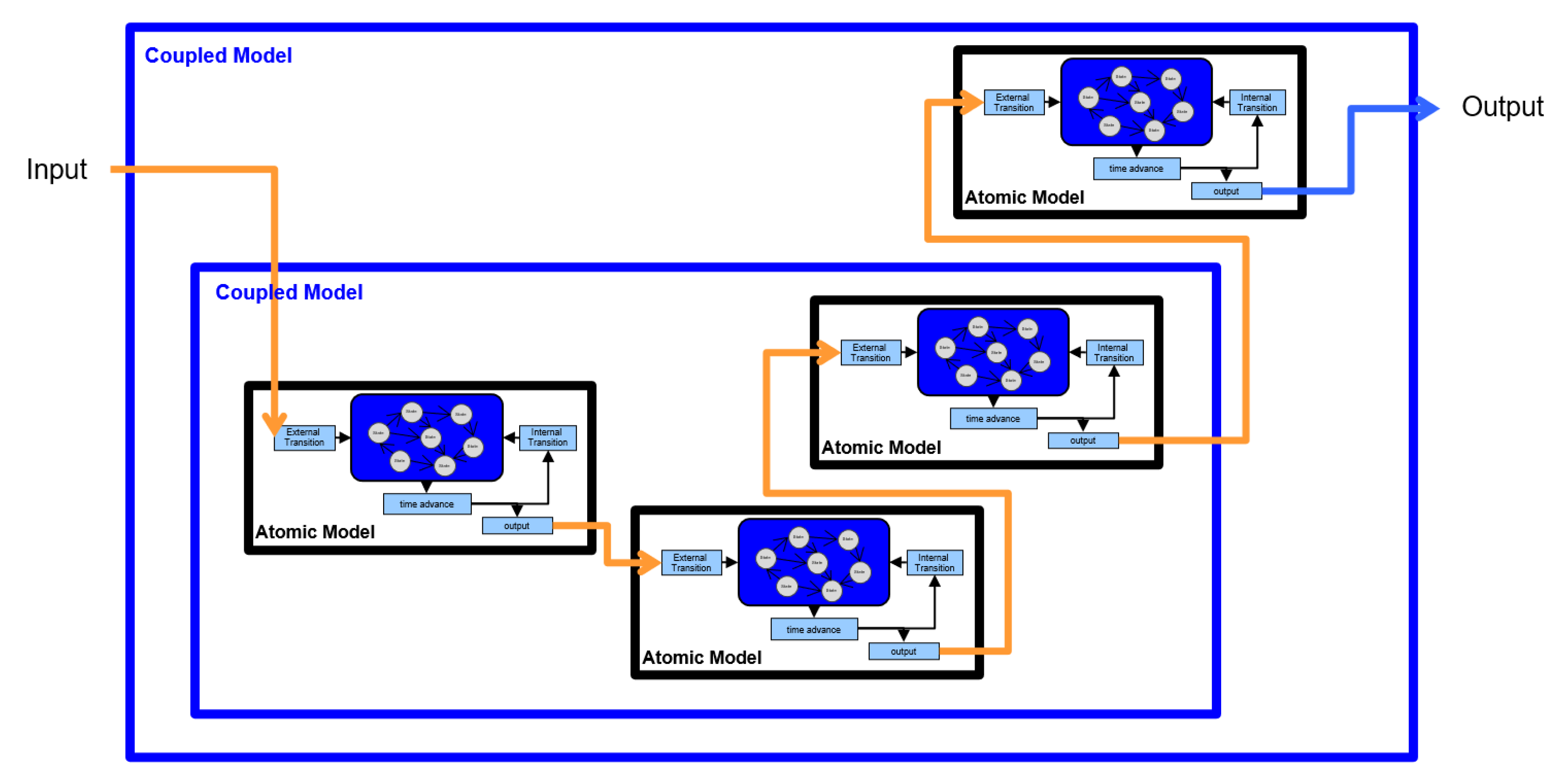
Figure 4.
IoCT Solar System Architecture designed and implemented using DEVS syooirt for expressiveness and continuity.
Figure 4.
IoCT Solar System Architecture designed and implemented using DEVS syooirt for expressiveness and continuity.
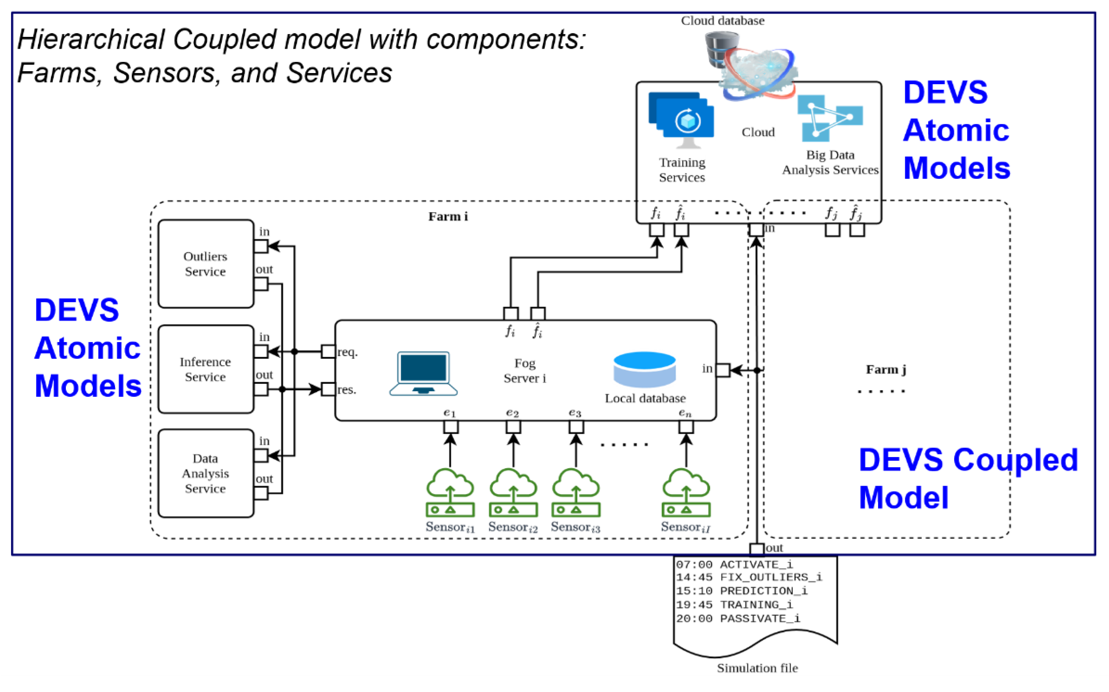
Figure 6.
IoCT systems face two conflict types: (a) Direct conflicts, where N application flows compete for an actuator’s resources; (b) Indirect conflicts, where N application flows affect MM devices through environmental characteristics (e.g., noise). An ACM DEVS Coupled Model is introduced to simulate and validate resolutions for both conflict types.
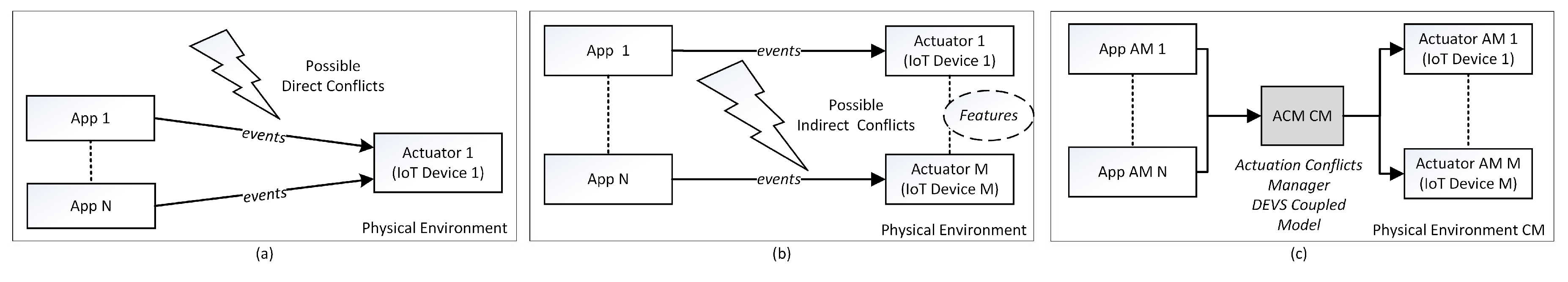
Figure 7.
The ACM component model, featuring its Synchronizer and Logical Behavior models, is embedded within a Physical Environment that includes Application flows and IoCT Devices (Actuators).
Figure 7.
The ACM component model, featuring its Synchronizer and Logical Behavior models, is embedded within a Physical Environment that includes Application flows and IoCT Devices (Actuators).
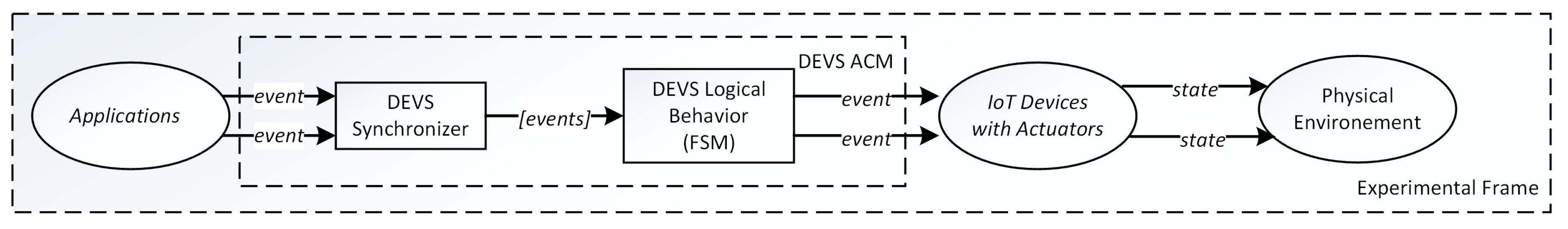
Figure 8.
The DEVSimPy model of the Smart Home scenario integrates the ACM model with the coupled application flows and actuators. The Synchronizer and LogicalBehavior models are part of the ACM coupled. model.
Figure 8.
The DEVSimPy model of the Smart Home scenario integrates the ACM model with the coupled application flows and actuators. The Synchronizer and LogicalBehavior models are part of the ACM coupled. model.
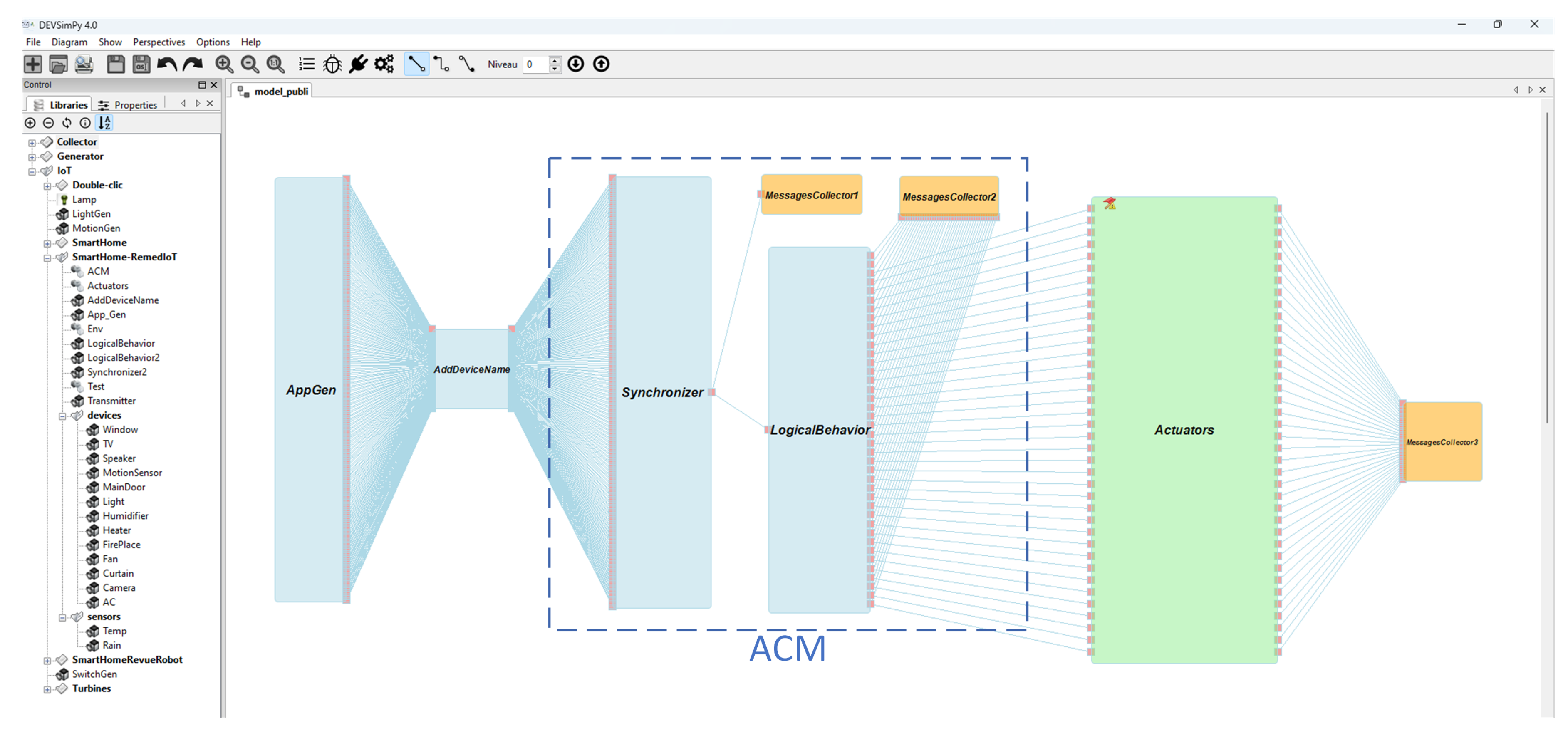
Figure 9.
The DEVSimPy simulation model integrates all the DEVS atomic models along with their interconnections. The simulation considers 10 drivers and 10 parking spaces. A Conflict_Collector model is employed to gather simulation outputs, which are subsequently used for result analysis.
Figure 9.
The DEVSimPy simulation model integrates all the DEVS atomic models along with their interconnections. The simulation considers 10 drivers and 10 parking spaces. A Conflict_Collector model is employed to gather simulation outputs, which are subsequently used for result analysis.
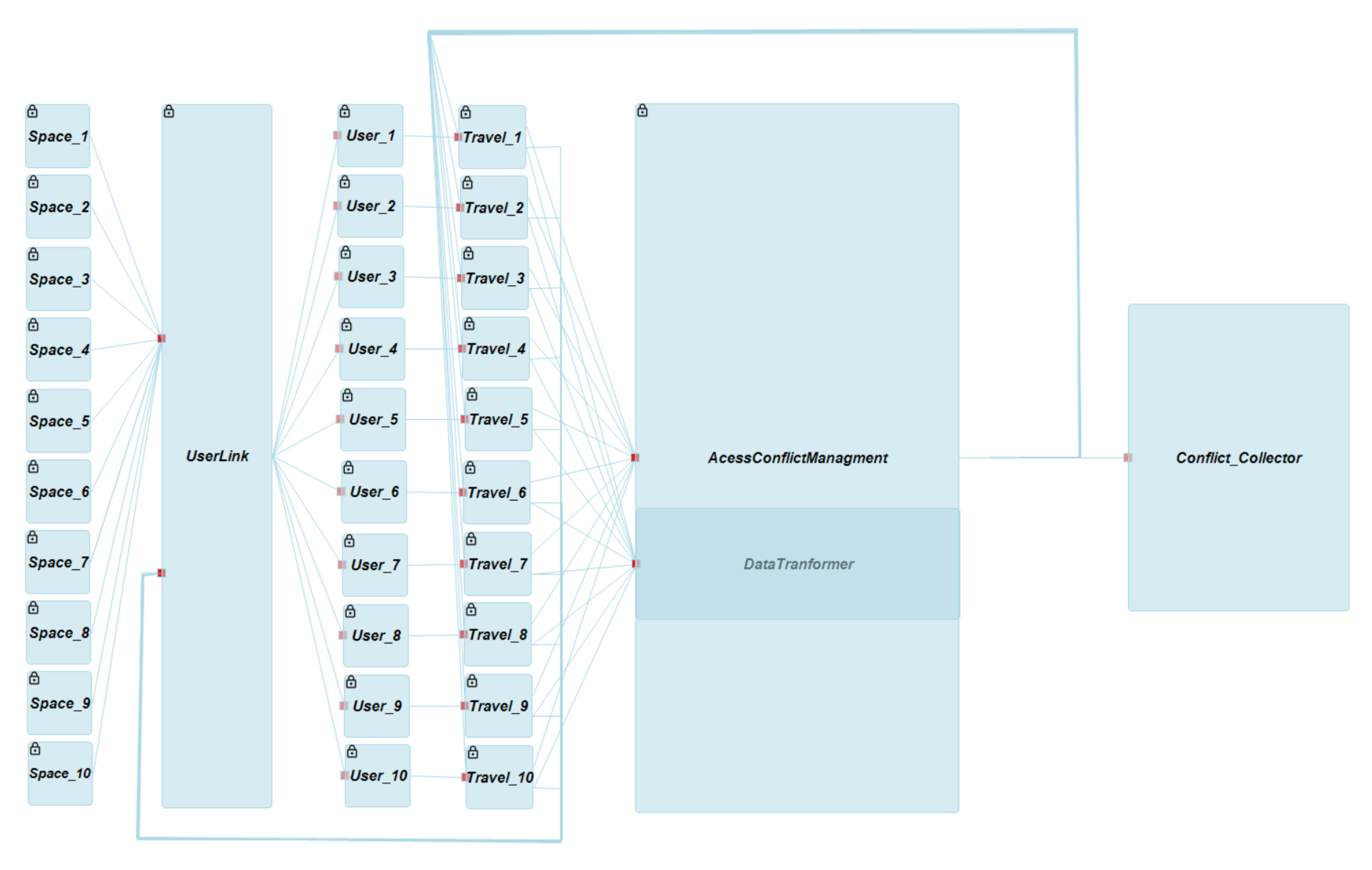
Figure 10.
Mobile app that embed the Smart parking DEVS simulation model for the Bastia city (Corsica - France) which is equipped with more than 400 presence sensors on the roads.
Figure 10.
Mobile app that embed the Smart parking DEVS simulation model for the Bastia city (Corsica - France) which is equipped with more than 400 presence sensors on the roads.
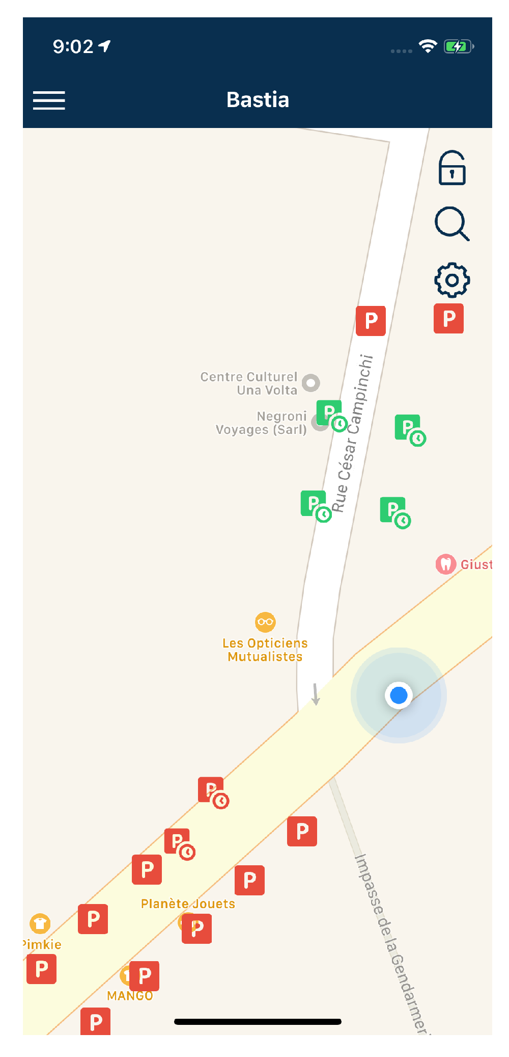
Figure 11.
Dynamic Structure DEVS Objective: minimize overlapping coverage areas. Figure copied and modified with permission.
Figure 11.
Dynamic Structure DEVS Objective: minimize overlapping coverage areas. Figure copied and modified with permission.
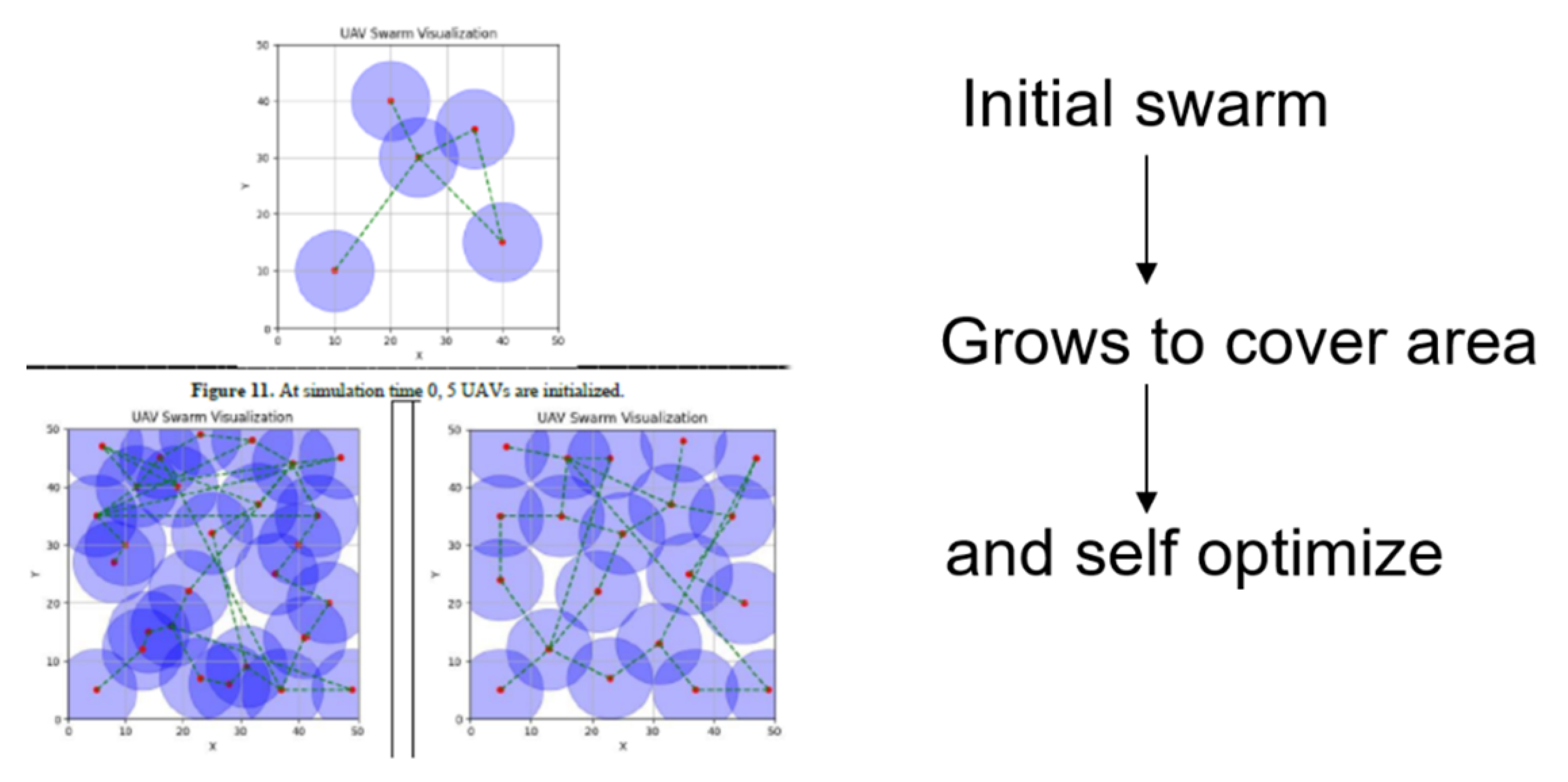
Figure 13.
Sketch of the system Entity Structure for unmanned swqrm system centralized and decentralized synchronization. This SES is described by the text in Figure 14.
Figure 13.
Sketch of the system Entity Structure for unmanned swqrm system centralized and decentralized synchronization. This SES is described by the text in Figure 14.
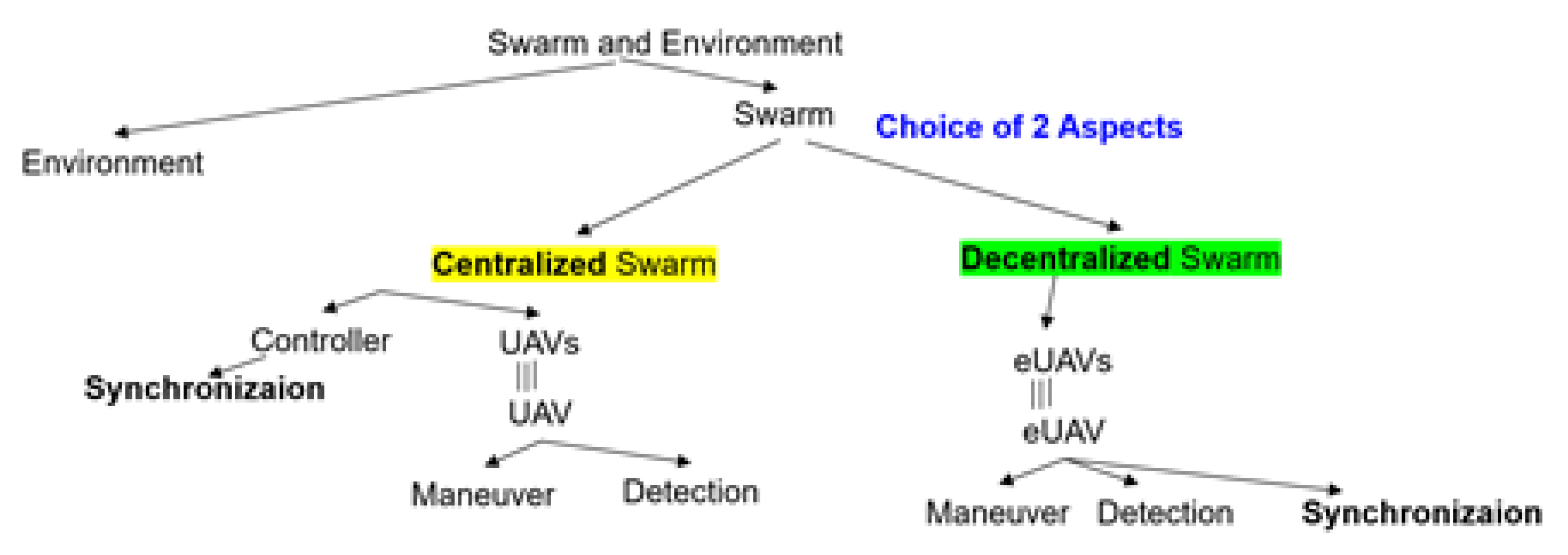
Figure 14.
Example of a SES description using constrained natural language. The text specifies a hierarchical coupled model that can be constructed from one ot the two aspects corresponding to centralized and decentralized control (shown in yellow and green, respectively.
Figure 14.
Example of a SES description using constrained natural language. The text specifies a hierarchical coupled model that can be constructed from one ot the two aspects corresponding to centralized and decentralized control (shown in yellow and green, respectively.
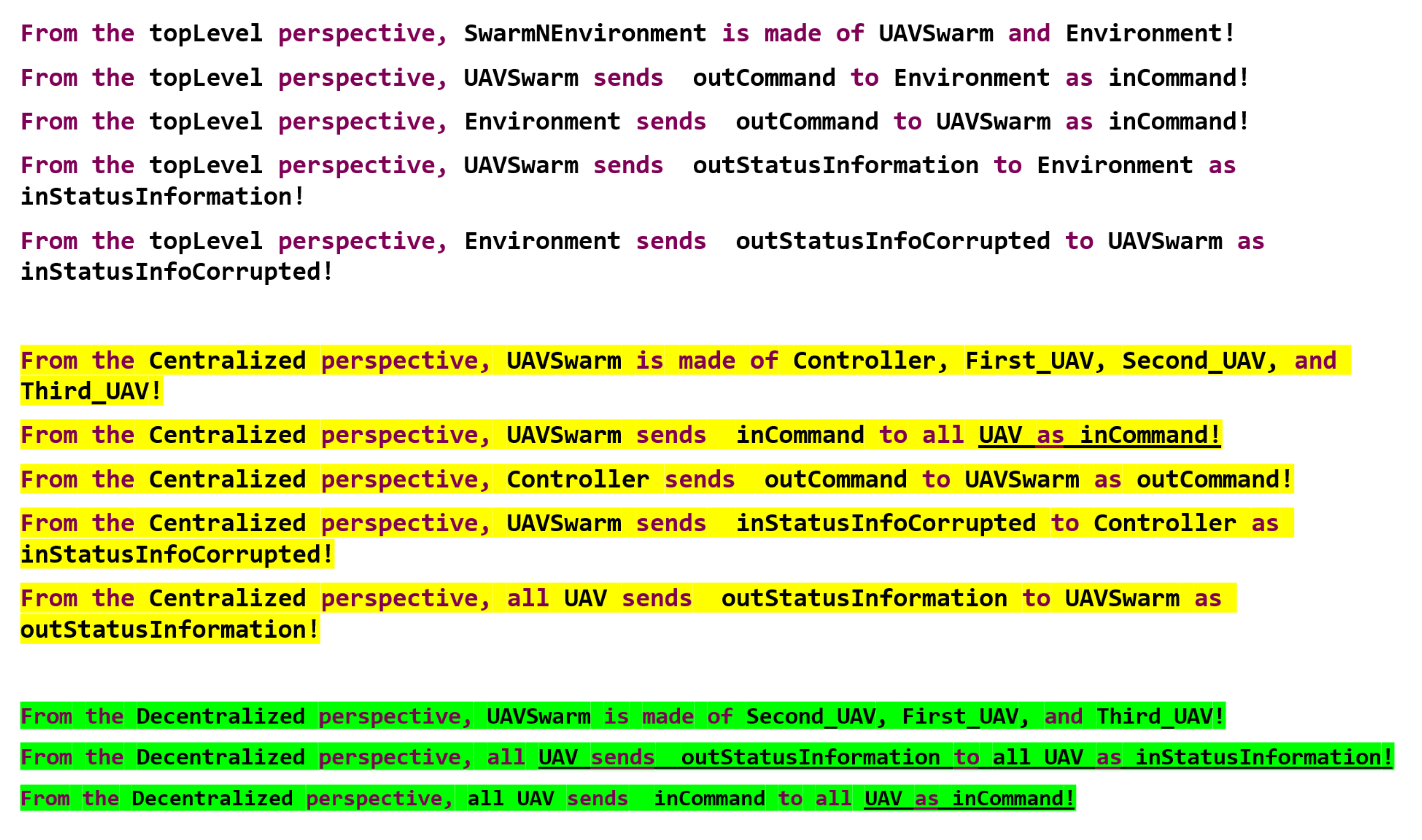
Figure 15.
Architecture that leverages DEVS capability to express building blocks for both the computational and control-theoretic functions required for intelligent cyber-physical system design.
Figure 15.
Architecture that leverages DEVS capability to express building blocks for both the computational and control-theoretic functions required for intelligent cyber-physical system design.
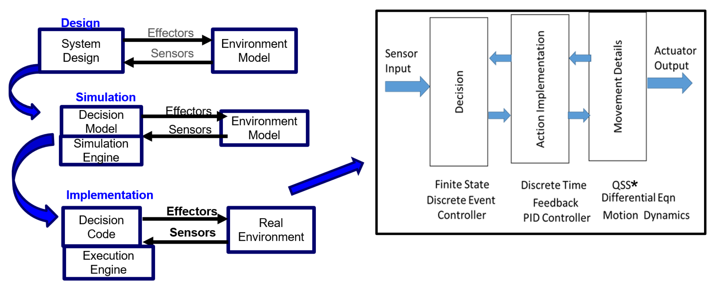

Table 1.
Model Expressiveness: Ability to Express Required Functionality in IoCT systems.
| DEVS Properties | Expressiveness Features |
|---|---|
| DEVS atomic model functions | capture microscopic behaviors (messages, timing, decisions), express temporal interaction with sensors and actuators |
| DEVS hierarchical modular construction | supports incrementally verifiable functionality, expresses collaborative interaction in centralized and decentralized control, expresses the IoCT architecture which is layered with sensor, Fog, and cloud layers |
| DEVS modularity | provides flexible support for the variable functionality required for AI/ML model analysis and retraining |
| DEVS temporal properties | express concurrent multiple streams of temporal events enabling simulation-based validation of the coordination and synchronization mechanisms |
| DEVS dynamic structure | enables structural changes needed for adaptive behavior |
| DEVS system-theory basis | supports definition of building blocks and architectural patterns for intelligent hybrid cyber-physical system design |
Table 2.
Model Continuity: Ability to Transition the “Same” Description from Stage to Stage.
| Inter-stage Transitions | DEVS Model Continuity Features |
|---|---|
| Migration from Design to Simulation | The DEVS Simulation engine is coded in a variety of programming and higher level languages for design and simulation |
| Migration from Simulation to Execution | DEVS Simulation engine can be transformed from its abstract time base to real-time bases and DEVS models can be converted to hardware or middleware forms for real-time execution |
| Diversity of implementation media | The DEVS simulation engine can be mapped to middleware implementations enabling straightforward integration with IoCT infrastructures, DEVS supports deployment across diverse hardware platforms with varying timing characteristics, underscoring its adaptability and portability, DEVS Execution engines can be implemented in diverse technologies such as virtualization, hardware, embedded systems, and bioware |
Table 3.
Comparison of Different Formalisms with DEVS.
| Formalism | Strengths | Limitations Compared to DEVS |
|---|---|---|
| Class Diagrams | Good for static structure modeling | Lacks temporal dynamics, reactivity, and execution models |
| State Machines | Effective for sequential control and finite states | No support for concurrency, hierarchical design, or modularity |
| Petri Nets | Excellent for concurrency and synchronization | Limited modularity, no inherent support for dynamic structures or execution strategies |
| SysML | Useful for complex system-of-systems modeling | Lacks native simulation support and real-time execution capabilities |
Disclaimer/Publisher’s Note: The statements, opinions and data contained in all publications are solely those of the individual author(s) and contributor(s) and not of MDPI and/or the editor(s). MDPI and/or the editor(s) disclaim responsibility for any injury to people or property resulting from any ideas, methods, instructions or products referred to in the content. |
© 2025 by the authors. Licensee MDPI, Basel, Switzerland. This article is an open access article distributed under the terms and conditions of the Creative Commons Attribution (CC BY) license (http://creativecommons.org/licenses/by/4.0/).
Copyright: This open access article is published under a Creative Commons CC BY 4.0 license, which permit the free download, distribution, and reuse, provided that the author and preprint are cited in any reuse.


