Submitted:
16 May 2025
Posted:
17 May 2025
You are already at the latest version
Abstract
This paper presents a comprehensive review of Direct Interface Circuits (DICs), which provide a compact, cost-effective, and energy-efficient alternative for interfacing with sensors that exhibit electrical variations such as resistance, capacitance, and inductance. A distinctive characteristic of DICs is their ability to connect sensors directly to digital processors, including microcontrollers (MCUs) or Field-Programmable Gate Arrays (FPGAs), through RC, RL, or capacitive charge transfer configurations, without the need for additional signal conditioning components. The review outlines the fundamental operating principles and key elements of DICs, including time-to-digital conversion, digital processing, and techniques for assessing measurement accuracy, resolution, response time, and the effects of uncertainty and interference. By synthesizing findings from recent literature, this study provides an in-depth understanding of current advancements in DICs and offers a critical analysis of their state-of-the-art implementations. Finally, strategic recommendations are proposed to guide future research directions and application areas.
Keywords:
Direct interface circuits (DICs)
; field-programmable gate arrays (FPGAs)
; microcontroller
; time-to-digital conversion
; sensor interface
1. Introduction
The rapid advancement of technology continues to pose new challenges in electronic instrumentation. There is an increasing demand for innovative, compact, and energy-efficient electronic systems capable of monitoring wireless sensors and sensor interfaces in various domains, including the Internet of Things (IoT) [1], wearable smart sensors for vital sign monitoring [2], and sensors deployed in smart city infrastructures [3]. These areas have garnered significant attention from the scientific community due to their broad impact and wide range of potential applications.
In many cases, the measurement of electrical quantities such as resistance, capacitance, and inductance is essential for interpreting sensor responses associated with physical phenomena (e.g., pressure, distance, temperature, etc.). Figure 1 shows a conventional sensor interface architecture, wherein the sensor signal is processed through an analog signal conditioning stage that typically involves amplification, filtering, linearization, and analog-to-digital conversion (ADC) [4], followed by digital processing using a digital processor such as microcontroller unit (MCU) or Field-Programmable Gate Array (FPGA) [5].
In recent years, an alternative approach in electronic instrumentation has emerged for measuring sensors with resistive, capacitive, or inductive variations without the need for traditional signal conditioning stages. This technology, called direct sensor–microcontroller interface circuits, or Direct Interface Circuits (DICs), has gained acceptance due to its simplicity and efficiency [6,7]. Initially introduced in application notes by semiconductor manufacturers, these circuits have proven highly practical for sensor interfacing.
Early implementations are typically categorized into charge time-based [8,9,10,11] and discharge time-based circuits [12,13]. Both rely on RC configurations where a digital processor excites the analog sensor to produce a time-domain modulated signal. This signal is then digitized through a time-to-digital conversion (TDC) mechanism embedded in the processor’s internal timer. The resulting signals, commonly referred to as quasi-digital signals [14], have formed the basis for numerous studies targeting resistive [15,16,17], capacitive [18,19,20], and inductive [21,22] sensors. These approaches enable compact and efficient sensor-to-processor interfaces, offering a compact size and energy-efficient solution due to their significantly low power consumption in active modes. This reduces the overall draw compared to traditional measurement methods and minimizes the need for additional components. This simplification allows for a smaller physical footprint of the entire circuit, offering significant benefits in reduced cost, minimized circuit size, and lower power consumption [7].
DICs could emerge in areas where real-time data acquisition is necessary, which facilitates quick and direct measurements from sensors (e.g., health monitoring, environmental sensing, and smart home systems), and its simplicity in scalability for IoT systems where more of one sensor can be added without significantly increasing the complexity of the circuit, leading an energy efficient system, making it feasible to create large networks of interconnected devices. However, challenges remain in achieving high accuracy, resolution, and optimal measurement time, as these performance metrics are closely influenced by uncertainties in the time-to-digital conversion process [23]. Additionally, these circuits are susceptible to interference from power supply fluctuations [24] and uncertainties in detecting quasi-digital signals. These uncertainties are primarily related to the voltage thresholds VTL and VTH used to detect the sensor signal at a specific voltage level Vc of the digital processor, directly impacting the resolution and reliability of the measurement process [6].
1.1. Related Works
This review constitutes a follow-up to the works presented by Reverter in [7], which introduced the concept of directly interfacing sensors to microcontrollers (MCUs). That initial work established fundamental design guidelines to simplify sensor interface circuitry, focusing on power efficiency and reliable performance. It highlighted the cost-effectiveness of such approaches for various resistive and capacitive sensors and proposed future directions for broadening their applicability in modern electronic systems. Additionally, Reverter [86] presented a book chapter discussing DIC's principles and applications for some commercial sensors, and [30] related to advanced techniques for resistive sensors and their performance in some applications.
However, the scope of these early works was primarily centered on explaining the operating principles of direct interface techniques and evaluating their performance, efficiency metrics, and applications in commercial sensors at that time. These insights motivated a deeper investigation into this research area to explore recent advancements and emerging trends. The aim of this paper is to provide a comprehensive review and analysis of published papers on Direct Interface Circuits (DICs) up to the year 2025. This includes a detailed examination of their key components and the application of advanced techniques to enhance accuracy, resolution, and power efficiency. The contributions of this review are as follows:
- A comprehensive overview of the operating principles, core components, and implementation techniques of DICs for resistive, capacitive, and inductive sensors.
- A critical analysis of recent publications proposing improved methods to enhance measurement accuracy, resolution, acquisition time, and uncertainty management in DIC-based systems.
- An assessment of current application domains for DICs and strategic recommendations for future research efforts.
- A discussion of the most significant advances to date and the remaining technical challenges that must be addressed for broader adoption of DICs in future instrumentation systems.
1.2. Paper Organization
The structure of this paper is outlined in Figure 2. Section I introduces DICs as an alternative for sensor interfacing and presents the main contributions and review methodology. Section II offers an overview of the key elements and characteristics of DIC implementation. Section III details various types of direct interface circuits, explaining their operating principles and reviewing enhanced techniques based on RC, RL, and capacitive charge transfer methods. Section IV analyzes the literature by circuit type, sensor type (resistive, capacitive, inductive), and digital processors used in DICs, concluding with relevant application areas. Section V discusses the review findings, emphasizing recent advancements, challenges, and recommendations for future research. Finally, Section VI summarizes the conclusions of the study.
1.3. Review Methodology
This review focuses on DICs applied to resistive, capacitive, and inductive sensors and follows a systematic literature review methodology. To identify relevant publications in the field, the initial search was conducted using specific keywords and inclusion criteria across several well-established digital databases, including IEEE Xplore, ScienceDirect, MDPI, and Springer Link, as well as bibliographic search engines such as Google Scholar and Scopus.
The primary inclusion keywords used were “direct interface circuits” and “sensor interfaces.” An initial screening process utilized publication titles and abstracts, guided by exclusion and inclusion criteria, to filter out unrelated content. The selected documents included peer-reviewed journal articles, application notes from semiconductor manufacturers, and technical books related to sensor interfacing. The inclusion criteria for the literature review were as follows: (i) Publications describing sensor interfaces based on the operating principles of direct connection to a digital processor (e.g., MCU or FPGA); (ii) Studies presenting novel methods or enhanced techniques related to DICs; (iii) Analytical reviews or comparative studies; and (iv) Application notes demonstrating practical implementations of DICs.
This selection process enabled the identification of critical insights into the operational principles, measurement ranges, accuracy, resolution, acquisition time, sources of systematic error, and power consumption associated with DIC-based systems. This comprehensive search selected 99 references—including papers, books, book chapters, application notes, and support papers—for this work, focusing on RC, RL, and capacitive charge transfer configurations. Figure 3 provides a classified overview of the search results, highlighting the distribution of the reviewed literature: DICs with RC components represent the most extensively studied field, accounting for 54% of the review, followed by DICs with RL components (6%), DICs employing capacitive charge transfer techniques (5%), general application notes reported in literature (21%), and support papers (14%).
2. Elements of a DIC
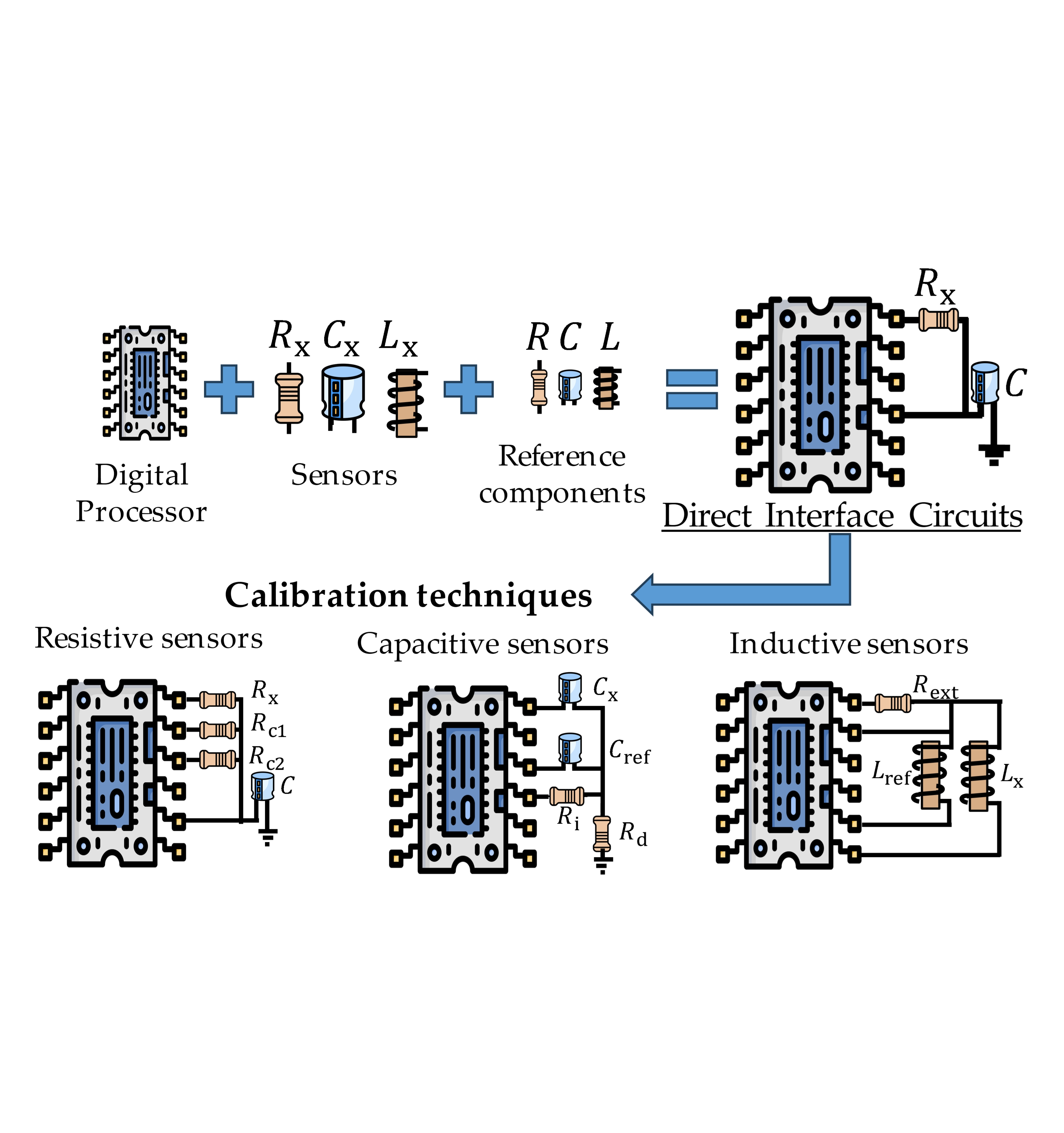
The fundamental elements of a DIC connecting a sensor to a digital processor are designed to minimize the use of external components. These elements facilitate the excitation of the sensor and the acquisition of a quasi-digital signal in the time domain, which is subsequently digitized by a time-to-digital converter (TDC). This process enables the estimation of the corresponding electrical variable—resistance, capacitance, or inductance—without the need for traditional analog signal conditioning, as shown in Figure 4. Within this context, the following sections examine a summary of the key components and their characteristics to provide a clear understanding of the operating principles underlying DIC implementations.
2.1. Sensors
Pallás-Areny et al. [25] describe resistive sensors as devices that vary their electrical resistance R, either directly or indirectly, in response to changes in a physical quantity. These sensors can be classified into three main types, as shown in Figure 5. The first type, simple resistive sensors, consists of a single resistive element Rx, offering a straightforward and effective solution for basic sensing applications. The second type, differential resistive sensors, incorporates two sensing elements, Rx1 and Rx2, sharing a common terminal and exhibiting opposite response variations. This configuration enhances accuracy by reducing noise and improving measurement reliability in high-precision environments. The third type, bridge-type resistive sensors, uses one, two, or four sensing elements arranged in quarter-bridge, half-bridge, or full-bridge Wheatstone configurations. These resistive sensors are widely employed in measuring temperature (e.g., platinum resistance thermometers and thermistors), light (e.g., Light Dependent Resistors), gas (e.g., tin dioxide sensors), humidity, and displacement using linear or rotary potentiometers.
Capacitive sensors, which represent another key category in sensor interfaces, exhibit changes in capacitance due to variations in dielectric properties or geometric factors such as plate area or distance. According to Pallás-Areny et al. [25], capacitive sensors can be categorized into four types, as depicted in Figure 5. Simple capacitive sensors utilize a single capacitance element Cx, providing an essential and effective sensing configuration. Lossy capacitive sensors account for real-world effects by modeling parasitic conductance Gx in parallel with Cx, enhancing accuracy by considering energy losses. Differential capacitive sensors improve sensitivity and noise immunity by incorporating two elements, Cx1 and Cx2, with a shared electrode and opposite response characteristics. Finally, bridge-type capacitive sensors employ one, two, or four sensing elements in bridge configurations to achieve high precision and stability. These sensors are utilized in various applications, including liquid level detection, humidity sensing, gas detection, pressure monitoring [7], and fluid concentration analysis [20].
Inductive sensors represent the third major category commonly used in industrial applications to measure displacement between metallic objects and other physical quantities, such as pressure [26]. These sensors rely on variations in magnetic reluctance, which correspond to changes in magnetic flux due to an electric current. When this current flows through the system, it is associated with inductance Lx. Pallás-Areny et al. [25] classify inductive sensors into several types, four shown in Figure 5. These include topologies with inductance variation based on the number of coil turns in both simple and differential configurations and designs involving the movement of a ferromagnetic core, again in either simple or differential arrangements.
Recently, Reverter [99] presented a review of remote resistive sensors, which are physically located in harsh, inaccessible environments, or far from the primary measurement and control systems. These remote sensors commonly involve parasitic resistances and temperature variations, which affect measurement accuracy. Some wire-resistance techniques are studied to compensate for the parasitic resistances of connecting leads. For example, three-wire resistive sensors (Figure 6a) are designed to cancel out the parasitic resistances of the wires [78,79], with the third wire used for current supply, while four-wire resistive sensors (Figure 6b), known as the Kelvin connection, use four wires: two for supplying the excitation current and two separate sense wires for measuring the voltage across the sensor [76].
Resistive, capacitive, and inductive sensors are essential for converting physical magnitudes into measurable electrical signals. Given the focus of this work, a thorough understanding of sensor types and their configurations—whether simple, differential, or bridge-based—is crucial for developing efficient DIC techniques that integrate robust, low-cost sensor interface systems.
2.2. Time-to-Digital Converter
A Time-to-Digital Converter (TDC) is a crucial electronic component in systems that require precise and accurate measurement of time intervals. Its primary function is to convert time-domain information, typically defined by the interval between two signal events, such as pulse width or period, into a digital representation. A simplified explanation of TDC operation is provided by Henzler [27], who refers to it as a digital technique based on simple counting. In this approach, a time interval Tx is measured by counting the number of cycles of a reference clock Tref using a universal counter, as illustrated in Figure 7. The interval is defined by the rising edges of a start and stop signal, and the result is digitized as Ts. Since these events are generally asynchronous to the reference clock Tref, timing errors may be introduced at both the start (TStart) and stop (TStop) edges due to the limited resolution of Tref. This resolution can be enhanced by increasing the clock frequency; however, this also leads to higher power consumption and imposes additional design constraints.
TDCs share conceptual similarities with Analog-to-Digital Converters (ADCs). In the case of ADCs, the measured voltage is compared against a reference voltage Vref, with the quantization step defined as VLSB = Vref/2N, where N is the number of resolution bits. In contrast, TDCs do not use a reference voltage. Instead, they rely on a quantization time TLSB, which represents the minimum time interval that the TDC can detect. The reference time Tref in TDC terminology denotes the maximum time interval that can be measured and is defined as Tref = 2N·TLSB. These parameters define TDC-based systems' trade-offs between resolution, dynamic range, and power consumption. Understanding this relationship is crucial for designing time-sensitive digital systems capable of effectively measuring and digitizing time intervals.
In summary, a TDC, a key element of a DIC, measures the time interval between events or a signal's time to reach a certain threshold, converting this timing information into a digital value. On the other hand, an ADC focuses on measuring the amplitude of an analog signal at a specific moment and translating that voltage into a digital format. One advantage of implementing a sensor interface with a TDC is that it offers a simpler circuit in components (only resistors and capacitors are needed for basic setups) and can be more cost-effective in specific applications. Generally, noise affects TDC measurements less than voltage readings at ADCs, making them effective in noisy environments, as they focus on time intervals rather than signal levels [7].
2.3. Digital Processor
A digital processor is a programmable electronic device widely used in measurement systems for data acquisition, signal processing, and the execution of complex control algorithms. Its architecture determines its capabilities, with standard implementations based on microcontroller units (MCUs), which typically integrate 8-bit, 16-bit, or 32-bit processing units responsible for managing data and instruction cycles. MCUs include non-volatile Flash memory for storing program code, random-access memory (RAM) for data processing, and various integrated peripherals. These peripherals often include analog comparators, ADCs, digital timers, Digital-to-Analog Converters (DACs), communication interfaces (e.g., USART, SPI, I²C), and general-purpose digital input/output (I/O) pins [28].
An alternative to MCUs is Field-Programmable Gate Arrays (FPGAs). FPGAs consist of configurable logic blocks that can be flexibly interconnected to implement custom digital functions. Like MCUs, they can also incorporate peripheral components, providing a versatile and cost-effective platform for the implementation of complex digital systems [29]. Digital processors play a critical role in DIC implementations by enabling the direct connection of sensors to the processor’s digital pins and by leveraging embedded digital timers and counters [6]. These processors typically include a counter or timer module to measure time intervals. An input signal can be applied to a digital pin and compared against voltage thresholds through an internal digital buffer [23]. The processor’s Central Processing Unit (CPU) detects voltage crossings via polling or interrupt-driven mechanisms and triggers the counter or timer accordingly. This functionality is based on TTL/CMOS Schmitt trigger inputs, which define a low voltage VTL and a high voltage VTH. The rising edge of the input signal, when it exceeds VTH, marks the start of the time interval, while the falling edge, when it drops below VTL, defines the end. The counter increments or decrements its value every Tref seconds, where the digital processor's internal oscillator determines Tref. In this way, the digital processor is responsible for exciting the sensor and processing the DIC signal response using the specific interface technique described in the subsequent sections.
3. Direct Interface Techniques
This section summarizes the fundamental direct interface techniques reported in the literature, categorized by the type of circuit used to measure sensors with resistive, capacitive, or inductive characteristics. Each technique leverages the intrinsic properties of these sensors and employs minimal external circuitry to connect them directly to digital processors. The operating principles, circuit configurations, and performance considerations related to each sensor type are discussed in detail in the following subsections.
3.1. Circuits with RC Components
Reverter et al. [6] introduced a basic RC circuit to explain the operational principle of DICs applied to resistive sensors connected directly to an MCU. As shown in Figure 8, the circuit comprises a resistive sensing element Rx and a capacitor C, forming a simple network capable of estimating the sensor's electrical parameters through time-to-digital conversion of the capacitor’s charging and discharging processes. In this configuration, the MCU interacts with the circuit using digital output and input pins, denoted as Pd1 and Pdp.
The principle of operation relies on measuring the time interval required to charge (Tc) or discharge (Td) the capacitor C through the resistive element Rx, until a voltage threshold is reached—either the upper threshold VTH or lower threshold VTL, depending on the operation mode. This time interval serves as the basis for estimating the resistance or capacitance of the sensor [7]. This type of DIC can be conceptually interpreted as a classical RC circuit. Assuming the capacitor C is initially discharged (i.e., at 0 V), and a voltage stimulus V1 is applied to the circuit input, the transient voltage response across the capacitor can be analyzed using the exponential function described as
and the time required to charge C from 0 V to a high threshold voltage VTH as
proportional to R, and if C is charged to a voltage level V1, it can be directly discharged to ground from its entry point as is shown in Figure 8, resulting in a transient response in its output voltage Vo(t) as
Therefore, the period to discharge C from V1 to a low threshold voltage VTL can be estimated by using (4),
This implies that any variation in the sensor’s resistance is directly proportional to the measured time interval [30]. Consequently, the measurement process is executed in the digital processor in two distinct stages: the charging and discharging of the capacitor C. Table 1 summarizes this process, detailing the states of the digital pins and the intervals required to complete each phase.
During this operation, the embedded digital timer measures the time taken for the capacitor voltage to cross the lower threshold voltage VTL of the Schmitt Trigger buffer connected to the input pin Pd1. The resulting digital count is directly proportional to the resistance value Rx. This methodology allows for the conversion of analog resistance into a time-domain signal, which can be digitized and processed by the MCU to estimate Rx, as described by equation (4). While this basic configuration permits effective resistance measurement, it does not account for inherent offset or zero errors.
To address this limitation, various authors have proposed a modification of the basic DIC, incorporating a single-point calibration technique [10,11,13]. As shown in Figure 9, this enhanced configuration introduces a known calibration resistor Rc1, which is measured similarly to the sensor Rx. During the measurement cycle, the charging and discharging stages produce two digital counts: Nx, corresponding to the sensor resistance Rx, and Nc1, obtained from the calibration reference Rc1. This correction mechanism allows compensation for systematic errors and improves measurement accuracy.
This calibration procedure assumes a linear relationship between Rx and Nx, with no zero-offset or non-linearity error requiring further compensation. As a result, both measured values, (Rc1, Nc1) from the calibration stage and (Rx, Nx) from the sensor, can be used to define a calibration line that passes through the origin (0,0) and the reference point (Rc1, Nc1). This linearity allows for the compensation of systematic errors in the measurement process for any Rx value within the range of the calibration point. Accordingly, an estimated value of the sensor resistance Rx can be calculated using equation (5),
Table 2 summarizes the configuration of the digital processor’s pins, and the associated measurement procedure used to estimate the sensor resistance Rx through the acquisition of the digital counts Nx and Nc1.
In a similar context, Richey [11], from Microchip, proposed a DIC for capacitive sensors, incorporating a single-point calibration using a reference capacitor Cref. The circuit is designed to perform two separate measurements: (i) acquisition of the digital count Nx corresponding to the sensor capacitance Cx; and (ii) acquisition of the digital count Nref from the known reference capacitor Cref, as shown in Figure 10.
The measurement methodology used to estimate Cx in Figure 10 follows the same operating principle as the resistance estimation technique described previously in Figure 9. However, the pin configuration and measurement setup differ depending on the measured component. Table 3 presents the corresponding MCU configuration for each stage of the measurement process [31].
The sensor capacitance Cx is then estimated using equation (6), which establishes a direct proportionality between the digital counts Nx and Nref, enabling accurate calibration and compensation.
Another approach Bierl [12] proposed from Texas Instruments introduces a two-point calibration technique. This method involves the sensor Rx and two calibration resistors, Rc1 and Rc2, as shown in Figure 11. The method is particularly effective when the sensor exhibits zero-offset errors, gain errors, or non-linear tendencies, which cannot be adequately corrected using a single-point calibration.
To compensate for these effects, the circuit performs three measurement cycles: a digital count Nx obtained from the sensor Rx; (ii) a reference count Nc1 measured from the calibration resistor Rc1; and (iii) a second reference count Nc2 obtained from the calibration resistor Rc2. Each measurement consists of six stages: three for the charging and three for the discharging phases, followed by time-to-digital conversion. Table 4 presents the digital processor configuration for acquiring the three discharge times.
This calibration process enables the construction of a correction curve that passes through the reference points (Rc1, Nc1) and (Rc2, Nc2), effectively compensating for offset, gain, and non-linearity errors. As a result, the resistance value Rx can be accurately estimated for a given digital output Nx using equation (7).
Van Der Goes et al. [32] proposed a two-point calibration technique for capacitive sensors, applied directly to the configuration shown in Figure 10, without requiring additional components. The method leverages a single known reference capacitor Cref and an open-circuit condition as the second calibration point. This approach enables two-point calibration using a minimal hardware setup.
To execute this calibration, the microcontroller performs three measurements: (i) a digital count from the sensor capacitance Cx; (ii) a count from the reference capacitor Cref ; and (iii) a counter under open-circuit conditions, which serves as the second reference point Coff. Table 5 summarizes the MCU pin configurations for each stage of the measurement process. Once the three measurements are acquired, the sensor capacitance Cx is estimated by equation (8),
Van Der Goes et al. [32] also proposed a three-point calibration technique for resistive sensors, which improves upon the previously discussed two-point calibration method. In this approach, the RC circuit shown in Figure 11 is modified by replacing the calibration resistor Rc1 with a short circuit, as shown in Figure 12.
This modification enhances the accuracy in estimating the sensor resistance Rx. In addition, the circuit includes an extra resistor R0, which limits the discharge current to the maximum value permitted by the digital processor’s output pin. This ensures that the resulting discharge signal retains a well-defined exponential behavior. Since the calibration process is not dependent on the exact value of R0, and its temperature-induced variation is negligible, this method provides a more cost-effective alternative for resistance measurement using DICs.
The measurement procedure used to estimate Rx follows the same principle as in the two-point calibration method. Table 6 presents the MCU configuration for each stage of the measurement process. The final value of the sensor resistance Rx can be computed using equation (9),
3.2. Circuits with RL Components
Kokolanski et al. [21] introduced a DIC for inductive sensors, as shown in Figure 13. This approach utilizes a microcontroller (MCU) with a reference inductor Lref to perform a single-point calibration, following a similar principle to that described in the previous section. An external resistor Rext is incorporated to regulate the current supplied from the digital processor to the sensor inductor Lx.
The interface consists of two RL circuits configured in a high-pass filter (HPF) topology: one comprising Rext and Lx, and the other consisting of Rext and Lref. Each circuit is energized by the digital processor to measure the discharge times, Tx and Tref, respectively, across the inductors. These time intervals enable the estimation of the sensor inductance Lx. HPF topology is chosen for its ability to provide an extended time constant, which results in longer discharge time and allows the use of smaller values for Rext. Additionally, this configuration leverages the parasitic output resistance of the MCU’s digital pin (denoted as Pd1 in Figure 13), which contributes to the effective series resistance in the RL circuit.
The measurement process involves two separate acquisitions: (1) a measurement from the sensor Lx, yielding the time interval Tx, and (2) a reference measurement using Lref, producing the interval Tref. Each acquisition is performed through a sequence of four stages. Stages 1 and 2 are associated with the excitation and time measurement of Lx, while stages 3 and 4 are used for the reference inductor Lref. Table 7 outlines the digital processor configurations and measurement sequence. The inductance Lx is then estimated using equation (10).
3.3. Circuits with Capacitive Charge Transfer
Gaitán-Pitre et al. [33] introduced the operational principle of a DIC based on the capacitive charge transfer technique, which can be analyzed analogously to a traditional RC circuit, as depicted in Figure 14. In this configuration, the sensor capacitance is represented by Cx, the charge transfer capacitor by Cr, and the supply voltage by Vs. These parameters are assumed to remain constant throughout the measurement process.
The interface operates through the control of a digital processor that counts the number of charge transfer cycles required to raise the voltage across Cr to a predefined threshold level. This method was initially proposed for capacitive sensors in [34,35] and has since been refined to enable accurate digital estimation of Cx. Table 8 outlines the measurement procedure for estimating Cx, consisting of three distinct stages. In each cycle, the charge stored in Cx is transferred to Cr, resulting in a voltage increment across Cr directly proportional to the charge transferred. Repeating the transfer charge increases the voltage across Cr until it reaches Vs, if Cr > Cx.
The total number of transfer cycles N required for Cr to reach the voltage threshold VTH is then measured. Assuming the initial condition Vr[0] = 0 V, and considering that Cr > Cx, the number of transfer cycles can be estimated using equation (11). Substituting into the corresponding expression, the sensor capacitance Cx is obtained using equation (12),
Dietz [34] presented the first experimental implementation of a DIC based on the capacitive charge transfer technique. The circuit, shown in Figure 15, includes the target sensor capacitance Cx and a reference capacitor Cr.
To account for non-idealities, the design also incorporates parasitic capacitances Cp0 and Cp1, which model the coupling between nodes 0 and 1 for ground and the MCU pins. The circuit further considers the internal output resistance of the MCU's digital buffer, modeled as ROL and ROH, which represent the resistance of the output transistor when a logic level ‘0’ or ‘1’ is applied, respectively. These resistances are assumed to remain constant during operation, provided the transistors function within their ohmic region, as discussed in [15]. The corresponding output voltage levels, VOL and VOH, represent the voltage levels at the MCU pins, respectively, when driven low or high.
The measurement procedure, detailed in Table 9, comprises three sequential stages: circuit initialization, the charging phase, and the charge transfer phase.
The charge transfer cycles are repeated until the voltage across Cr reaches the predefined threshold voltage VTH of the MCU input buffer. Under the condition that Cr > Cx, and considering the parasitic effects from Cp0, Cp1, and voltage levels VOL and VOH, the number of charge transfer cycles N is recorded. Finally, the capacitance Cx is estimated using (13),
Subsequently, Gaitán-Pitre et al. [33] introduced an enhanced DIC for capacitive sensing based on the charge transfer method, incorporating a two-point calibration technique designed to make the measurement results independent of VOH, VTH, and Cr. The proposed circuit is shown in Figure 16, and includes only the dominant parasitic capacitances, which are considered the most significant contributors to measurement uncertainty.
This methodology involves performing three separate measurements: one corresponding to each of the reference capacitors Cc1 and Cc2, and a third for the sensor capacitance Cx. The charge transfer process is applied individually to Cc1 and Cc2 to estimate the number of charge transfer cycles required in each case. These measurements yield the digital counts Nx, Nc1, and Nc2, respectively.
The measurement sequence for each stage follows the same operational procedure previously described, and it is summarized in Table 9. It is important to note that during each measurement, unused MCU pins must remain configured as high-impedance inputs to prevent unintended charge paths. Once all measurements are completed, the sensor capacitance Cx is estimated using equation (14),
4. Analysis
This section presents a comprehensive analysis of DICs, organized into four parts. First, an overview is provided of the key contributions from semiconductor manufacturers through application notes, highlighting the practical implementation strategies proposed. Second, a detailed analysis is conducted on the various types of digital processors used in DIC implementations, focusing on circuits based on RC and RL components, as well as capacitive charge transfer techniques. The analysis considers performance metrics such as measurement range, accuracy, resolution, acquisition time, systematic errors, and power consumption as reported in the literature. Third, DIC application domains are summarized, outlining their relevance across different sensing technologies and use cases. Finally, a general discussion synthesizes the findings from the review, emphasizing advancements, limitations, and research opportunities for the future development of DIC-based systems.
4.1. Initial Scope of a DIC
The initial development of DICs was driven by semiconductor manufacturers, who introduced the concept through application notes. These early works proposed measuring the electrical value of resistors or capacitors by directly interfacing them with a MCU and measuring the charging or discharging time in an RC circuit. The measured time was compared to a fixed threshold voltage, enabling an estimation of the component's value without the need for an analog-to-digital converter (ADC).
Sherman [8], from Philips Semiconductors, demonstrated that using an 80C51 MCU, in conjunction with a timer, a monostable multivibrator, and a comparator, it was possible to establish a strong linear relationship between the charging time of an RC circuit and its capacitance or resistance. This work laid the foundation for the fundamental operating principle behind DICs.
In parallel, Webjör [9] from Motorola Semiconductors proposed a method for measuring resistance in temperature and pressure sensors using the MC68HC05 MCU. The method consisted of two measurement phases, calibration and sensor acquisition, allowing for improved accuracy through reference point definition, variability compensation, output normalization, and systematic error reduction.
Cox [10], from Microchip, described the implementation of a digital ohmmeter using a PIC16C5X MCU. The technique involved charging and discharging a capacitor to determine a time value associated with the sensor, followed by a calibration process designed to eliminate first-order errors such as offset, gain deviations, capacitance tolerances, power supply fluctuations, and temperature effects. A similar approach was proposed by Richey [11], also from Microchip, using a PIC16C622 MCU and an RC circuit to estimate resistance or capacitance by measuring the capacitor’s charging time to a fixed reference voltage, monitored via an analog comparator.
Additionally, Merritt [13] from Texas Instruments introduced a digital thermometer based on an RC circuit and the timers of the MSP430x325 MCU. This implementation obtained the sensor value by charging and discharging a capacitor through a thermistor and a reference resistor. This allowed the MCU to count clock cycles and determine the corresponding resistance, which was then converted into temperature.
These application notes collectively demonstrated the feasibility of minimizing external components in measurement systems by leveraging internal MCU resources. The proposed DIC strategies promoted the concept of direct sensor-to-MCU interfaces as a low-cost and compact alternative to traditional analog signal conditioning. These early developments showcased the potential of MCUs in measurement applications and laid the groundwork for a research field that continues to attract significant academic and industrial interest.
4.2. Implemented Digital Processors
Within DICs, the digital processor serves as the core computational unit responsible for interpreting and processing sensor signals. Specifically, in sensor interfacing applications, it integrates essential functionalities such as data acquisition, control logic, and communication, typically within a single embedded platform. DIC implementations leverage the digital processor’s ability to convert sensor responses into measurable time intervals using internal digital pins and embedded timers.
Table 10 summarizes the digital processors reported in the literature for DIC implementations, categorizing them based on their operating frequency, embedded timer resolution, timer measuring range, and operating voltage range.
As reflected in Table 10, MCUs constitute the most used digital processors in DIC systems. However, in recent years, FPGAs have gained relevance due to their higher processing capabilities and timing precision.
MCUs implementation typically operate within a frequency range of 4 MHz to 32 MHz. Notable exceptions include implementations at 84 MHz [22], 80 MHz [71], and 42 MHz [70], which demonstrate that increased clock frequency directly enhances the resolution of the embedded timer. Most MCUs have 16-bit timer-counters, while some high-performance devices, such as the SAM3X8E [22] and the D1 Mini ESP32 [71], offer 32-bit and even 64-bit timers, respectively. This expanded bit-width accurately measures longer time intervals and improves overall timing resolution.
FPGAs, by contrast, operate at significantly higher frequencies and offer enhanced timing resolution, often as precise as 20 ns, due to their configurable logic and high-speed clocks. Lower-frequency MCUs typically exhibit time resolutions ranging from 125 ns to 800 ns. Only a few MCU-based implementations achieve finer resolutions, in the range of 12.5 ns to 23.8 ns, and these are directly associated with devices running at higher clock speeds.
This analysis indicates that while MCUs dominate DIC applications due to their integration and cost efficiency, FPGAs provide superior precision and performance for high-resolution time measurement applications. Additionally, when comparing FPGAs and MCUs in a DIC implementation, the decision often involves balancing key trade-offs in flexibility, performance, power consumption, and cost. In contrast, FPGAs offer unparalleled flexibility for hardware design and exceptional performance for parallel tasks, which MCUs cannot match. However, this flexibility and performance come at an increased cost and higher power consumption. Meanwhile, MCUs provide an easier programming experience using high-level languages like C/C++, making them more accessible for general-purpose applications. FPGAs require expertise in hardware description languages (HDLs) like VHDL or Verilog. FPGAs are generally more expensive than MCUs but allow for extensive hardware customization. MCUs, on the other hand, have fixed architectures, limiting their ability to adapt to unique or complex requirements.
It suggests that the choice of an FPGA or MCU depends on the specific needs of the application (e.g., IoT sensor interfaces, Industry 4.0, and wearable smart sensors), such as the level of performance required, power efficiency, development resources, and cost.
4.3. DIC with RC Components
DICs based on RC components are the most widely adopted approach for sensor interfacing, particularly for sensors that exhibit resistive or capacitive variations. Numerous studies have been dedicated to improving accuracy, resolution, and measurement time and reducing sources of uncertainty and interference that impact system performance. Table 11 highlights the most relevant contributions and associated data collected for further analysis.
Reverter [76] presented a simple DIC for four-wire resistive sensors using an external single switch. This approach reduces the complexity and number of components required compared to traditional methods that often involve multiple switches and external circuitry, achieving a maximum non-linearity error at 0.05% FSS, and relatively rapid measuring time (approximately 10 ms) for low resistance values associated with sensors like the Pt100 temperature sensor, in a resistance range from 60 Ω to 220 Ω. According to [77], the Reverter contrasts an improvement where the sensor interface needs four external switches, where measurement time is directly affected around 60 ms.
Reverter [78] also proposed a DIC for three-wire resistive sensors. The circuit requires more charge-discharge cycles and a longer conversion time. Additionally, two wire resistances are expected to be equal; otherwise, there is an offset error. However, it is noted for requiring fewer external components than existing solutions, thereby reducing overall complexity and cost while maintaining measurement accuracy. Reverter presented measurement ranges from 60 Ω to 264 Ω with a non-linearity error of around 0.03% and 0.02% FSS, which enabled improvements over [79] and [80], where multiple comparators, operational amplifiers, and switches are needed to perform a three-wire sensor measurement.
Hidalgo [81] introduced two novel DICs for the digital readout of resistive sensors to mitigate the errors introduced by lead wire resistances by obtaining multiple time measurements during a single capacitor charge and discharge. The Two-Measurement Method (TMM) circuit utilizes two resistors and a capacitor to acquire two-time measurements to estimate the sensor's resistance. The Improved Method (IM) includes an additional resistor for a third time measurement, which reduces errors in estimating the resistance. Experimental results were obtained by configuring known resistances to ensure their combined resistance is significantly larger than the lead wire resistances, effectively diminishing their impact on sensor readings. Hidalgo presented experimental results with sensor measurements at 100 to 2000 Ω for lead-wire resistances from 0 to 100 Ω, achieving significant measurement accuracy with systematic errors as low as 0.12% for TMM and 0.15% for IM. Both proposals effectively address the challenges of lead-wire resistance in measuring resistive sensors, representing an improvement of [97], where measurements ranges from 1000 to 1100 Ω for lead-wire resistances from 0 to 10 Ω, achieved significant measurement accuracy with systematic errors at 0.33 %.
Reverter [82] presented DIC as capable of measuring non-linear resistive sensors, such as thermistors. The proposed circuit employs an autocalibration and linearization process by incorporating a reference resistor RCL in parallel with Rx, and the non-linear resistance of the thermistor is transformed into a more linear response. Reverter presented experimental results of the proposal circuit with a thermistor B57164K from TDK, with resistive variations approximately 5 kΩ to 30 kΩ. After hardware linearization, non-linearity reported to be less than 1% FSS. This approach conducts a highly integrated, low-cost, energy-efficient, and accurate measurement technique, with simplicity, auto-calibration, and adaptability benefits.
Areekath et al. [83] presented a DIC for capacitively-coupled resistive sensors, which has not been explored so far from the perspective of a DIC. These sensors are suitable for non-contact sensing applications such as water quality monitoring or other environmental measurements. Areekath et. al. presented experimental results with measurement ranges from approximately 50 kΩ up to 800 kΩ, corresponding to typical water conductivity monitoring, such as measuring water quality. On the other hand, the capacitance measurement range is not explicitly specified. However, it is evaluated in the order of a few picofarads, with experimental results showing maximum errors under 3% across these ranges. According to measurement time, the proposed DIC completes both resistance and capacitance measurements in approximately 10 ms. Additionally, the maximum error reported is about 0.91% for resistance measurements and 2.94% for capacitive measurements. This paper contributes to exploring alternatives for capacitively-coupled resistive sensors with DICs.
Hidalgo [36] presented a circuit designed for differential resistive and capacitive sensors, achieving measurement times of between 1.1 ms and 1.3 ms and non-linearity errors of 0.34 % Full Scale Span (FSS) for resistive sensors and 0.63 % FSS for capacitive sensors. These results correspond to practical resolutions of 11.4 and 10.8 bits, respectively. Compared to previous works by Reverter et al. [16], [19], this study demonstrated significant performance improvements. However, the method's disadvantage lies in the relatively long acquisition time per cycle, which may limit fast-monitoring applications.
In another work, Hidalgo et al. [37] introduced two simplified DICs for resistive sensors by reconfiguring the two-point calibration method described in [15], enabling resistance estimation through a single charge-discharge cycle. This approach resulted in a more compact configuration, shorter measurement time, and up to a 40% reduction in energy consumption. Subsequently, Hidalgo et al. [38] developed an innovative DIC for capacitive sensors that eliminates the need for calibration capacitors by using only two additional resistors and a Xilinx Artix 7 FPGA (XC7A35T). This configuration estimates the capacitance with a single charge and discharge cycle. Although resolution data is not reported, the authors indicate a maximum relative error of 1.01% and an average error of 0.41% across a range from 0.100 nF to 561 nF, with an estimated acquisition time of 0.12 ms per 1 nF.
Hidalgo [84] presented a DIC for capacitive sensors affected by parasitic series resistances to obtain reliable capacitance measurements in a single charging-discharging cycle with advantages in minimizing power consumption and eliminating errors caused by parasitic resistances, making it highly suitable for IoT and ambient intelligence applications. Hidalgo presented experimental results measuring capacitances from approximately 100 pF to 96 nF, maintaining as low as possible systematic error of about 0.37% within this range, even when parasitic series resistances are as high as 1200 Ω.
Hidalgo et al. [39] also proposed two new configurations for resistive sensors based on RC networks: the Two-Capacitor Interface (TCI) and the Single-Capacitor Interface (SCI). These approaches utilize only two digital pins, reduce power consumption, and achieve faster acquisition times compared to traditional two-point calibration techniques. The TCI configuration decreases measurement time by approximately 50%, while the SCI configuration attains a 75% reduction for resistance ranges between 221 Ω and 24.9 kΩ. Although no resolution values were provided, the study emphasizes the relationship between resolution and equivalent capacitance, indicating that higher capacitance enhances resolution, albeit with potential increases in uncertainty due to the discharge curve characteristics.
Hidalgo et al. [40] introduced the Quantization Error Reduction Method (QERM) to address quantization errors, which modifies the discharging process by simultaneously discharging the sensor and calibration resistors. This approach significantly reduces noise quantization and improves overall resolution. The method requires two calibration resistors, a load resistor, a capacitor, and an FPGA. For resistance measurements between 33 Ω and 8.169 kΩ, the maximum error for values near 33 Ω was 0.33 Ω, representing a 1.56 % relative error, in contrast to the 3.77 % error observed using the standard two-point calibration technique.
Hidalgo et al. [41] proposed the Short-Time Charging Calibration Method (SCCM), which shortens the charging phase and allows two measurements per discharge cycle, significantly reducing acquisition time. Compared to the two-point calibration method, SCCM reduced charge times from 40.96 μs to 1.92 μs, with a modest increase in error (0.2 % to 0.3 %) attributed to quantization effects at shorter time intervals, suggesting the alternative of increasing the clock frequency of the FPGA or the capacitance values. However, this may lead to higher power consumption or increased noise.
Further contributions by Czaja [46] involved using an ATXmega32A4 MCU with an embedded DAC and comparator to measure capacitance in humidity sensors, achieving errors below 0.07 pF and relative errors under 0.06 % for experimental measurement ranges between 100 pF to 225 pF. This method involved averaging 64 measurements to improve accuracy, making it highly suitable for low-power sensor networks.
Hidalgo et al. [42] presented the Improved Direct Interface Circuit (IDIC), which uses three calibration resistors to build a linear system for estimating resistance. Implemented on a PIC16LF1559 MCU and a Xilinx Spartan3AN FPGA, the IDIC outperformed the two-point method, reducing the error from 26.6 % to 5.5 % for resistances near 80.388 Ω. The maximum reported error with FPGA implementation was 3 %.
In [43], two Fast Calibration Methods (FCM I and II) were proposed, which use the smallest calibration resistor during discharge to reduce measurement time. These methods achieved conversion times between 0.413 ms and 0.553 ms and were up to 55 % faster than the two-point calibration technique. The reported measurement ranges span from 260 Ω to 9.963 kΩ, with measurements between 0.413 ms and 0.553 ms, conversion times up to 55 % faster, with consistent errors for different resistance values up to 2.198 kΩ. However, FCM II introduced higher errors at larger resistance values.
A few years later, Botín-Córdoba et al. [85] presented a DIC named quasi single-point calibration methods (QSPCMs) for resistive sensors that significantly reduce measurement time, maintaining acceptable accuracy. This proposal uses an initial calibration with two known resistors to establish baseline parameters, and subsequent measurements by measuring only one resistor, and a calibration process with the other. These methods incorporate accelerated discharge procedures as fast calibration methods [43]. These QSPCMs achieve a reduction of approximately 61% against those in [43] for the mean estimation time when performing 20 measurements across the resistance range of 267.56 Ω to 7.46 kΩ.
Czaja [45] proposed a mixed time-domain DIC using an ATXmega32A4 MCU, passive components, and a MOSFET-based switching network to measure resistance and capacitance. The method uses a voltage divider with a reference resistor to estimate sensor resistance, averaging 64 measurements and applying piecewise linear corrections. Resistance errors remained under 3 % from 100 Ω to 8.2 kΩ. Capacitive measurement errors were below 0.2 % for values between 100 nF and 12 µF. Nagarajan et al. [47] addressed cable-induced resistance errors using an ATmega328 MCU, reducing measurement error to 0.06 % for a Pt100 sensor. Their design allowed remote resistive sensors to be connected directly to the MCU without significant precision loss.
López et al. [64] developed a low-power DIC achieving 9-bit ENOB at 5 μJ for 1–1.38 kΩ and 1.9 μJ for 100–138 kΩ. López et al. [65] also presented a capacitor calibration-free DIC using only a reference resistor and the MSP430F1471 MCU. The design maintained uncertainties below 1 pF for capacitances between 33 pF and 4.7 nF.
Reverter [52] analyzed current consumption for resistive and capacitive DICs, reporting 1.5 mA and 0.6 mA, respectively, due to shorter charging times in capacitive sensors. Reverter et al. [20] addressed lossy capacitive sensors by correcting parasitic conductance using a calibration technique that maintains accuracy even in high-humidity environments. The design achieved a relative error of less than 1 %.
Sifuentes et al. [66] introduced a Vernier-based method to extend discharge time and enhance resolution without increasing power consumption. Jordana et al. [56] and Sifuentes et al. [17] implemented DICs for bridge-configured resistive sensors, achieving non-linearity errors of 0.4 % to 1.5 % FSR and validating measurement accuracy through time averaging.
Oballe-Peinado et al. [91] presented a development and experimental validation of a DIC using a FPGA for resistive sensor arrays. This approach eliminates resistive crosstalk and simplifies hardware by balancing sensing speed and precision, offering a practical and scalable solution for tactile sensing and other applications that involve resistive sensor arrays. The authors reported experimental results showing maximum relative errors as low as 0.066% for resistances ranging from approximately 200 Ω to 7.3 kΩ.
Additionally, Oballe-Peinado et al. [92] presented an enhanced DIC employing operational amplifiers with capacitive feedback to mitigate errors introduced by non-idealities of operational amplifiers and FPGA input/output drivers and applying calibration algorithms that effectively reduce crosstalk effects. These advancements enable larger measurement ranges with higher precision.
Kokolanski et al. [88] introduced a sensor interface and experimental validation of a continual one-point auto-calibration technique for DICs, improving the measurement range and reducing nonlinearity errors without the need for multiple calibration resistors. Experimental results are given for resistive sensors in the range of 1kΩ to 100kΩ, with the measured discharge times on the order of microseconds, generally spanning from a few microseconds for low resistances around 1 kΩ up to tens of microseconds for higher resistances around100 kΩ.
Reverter et al. [31,53,54], and [57] examined the effects of power supply interference, ENOB, and quantization uncertainty. The use of input capture modules significantly improved resolution, while general-purpose interrupts led to greater timing uncertainty. Oballe-Peinado et al. [44] proposed an FPGA-based smart capture module that filters noise and enhances timing precision. Yurish et al. [55] highlighted the role of oscillator stability, noting that clock sources can introduce uncertainty ranging from ±50 ppm to ±100 ppm depending on the oscillator type.
RC-based DICs have evolved significantly through advances in calibration methods, quantization error mitigation, low-power design, and embedded signal processing. These developments have reinforced DICs as a reliable, low-cost, and energy-efficient solution for resistive and capacitive sensor interfaces.
4.4. DIC with RL Components
The implementation of DICs with RL components is primarily oriented toward measuring sensors that exhibit variations in inductance. This approach targets sensor–microcontroller interfaces for inductive sensors. Table 12 highlights this principle's most relevant publications and experimental results.
Kokolanski et al. [21] introduced the first DIC for inductive sensors using a reference RL circuit based on RC circuit principles. The proposed system employed a PIC16F877A and an ATmega328P MCU, integrating a reference inductor and a current-limiting resistor to form two RL circuits. Using a single-point calibration method, the system achieved inductance estimation in the range of 0.01 mH to 1.0 mH, with an effective resolution of 10.5 bits and a non-linearity error (NLE) below 0.3 % FSS.
Later, Kokolanski et al. [60] improved the original design by incorporating external MOSFETs to reduce the overall resistance in the circuit, thereby increasing the time constant of the RL network. This enhancement led to more accurate measurements by extending the discharging period. As a result, an additional 0.6 bits of resolution were achieved compared to the high-pass filter (HPF) topology, and up to 2.2 bits compared to the low-pass filter (LPF) configuration. The system also controlled power consumption through an external resistor, limiting the peak current to 100 mA, with a 47 Ω resistor selected for the HPF setup.
Ramadoss et al. [22] proposed a DIC based on the ATSAM3x8E MCU for applications involving differential inductive sensors such as Linear Variable Differential Transformers (LVDTs) and Differential Variable Reluctance Transducers (DVRTs). The system achieved displacement measurement ranges of 0–25 mm for LVDTs and 0–10 mm for DVRTs. Two measurements per inductor segment were performed, with total measurement times up to 200 ms. The reported error of 0.77 % was primarily attributed to temperature variations and resistor mismatches, demonstrating suitability for industrial applications.
As previously mentioned in Section C, Czaja [45] developed a time-domain measurement technique applicable to resistance, inductance, and capacitance sensors. For inductive measurements, the experimental setup yielded relative errors of less than 0.3 % across a range of 0.1 mH to 30.0 mH, highlighting its potential as a low-cost and energy-efficient method for smart sensor systems.
Asif et al. [48] proposed a method to improve resolution in inductive DICs without external analog-to-digital converters (ADCs). The technique involved stepwise supply voltage modulation using either an MCU pin (ATmega328P) or an external source, in combination with resistance optimization. The circuit measured voltages during charge and discharge phases to identify inductive response and estimate inductance values. The setup achieved a resolution of 4 μH over a 0.01–1 mH range, with a maximum non-linearity error between 1.1 % and <0.4 %, corresponding to an ENOB of 7.9. The system maintained low power consumption with a peak current of less than 40 mA.
Kokolanski et al. [49] demonstrated a practical displacement sensing application using DIC and a single inductive element with an ATmega328P MCU. The system used a Vernier Caliper to validate displacements in the ±50 mm range. The circuit achieved a resolution of approximately 9 bits and non-linearity errors of 1 %. Both HPF and LPF topologies were evaluated, demonstrating a reduction in complexity, cost, and power consumption compared to conventional analog interfaces.
Anarghya et al. [50] addressed error sources in inductive DIC implementations, identifying parasitic resistance and capacitance from MCU I/O pins and inductors as contributors to signal distortion and measurement instability. The presence of trigger noise and quantization effects during time-to-digital conversion also degrades accuracy. The authors suggested future improvements in shielding, grounding, and digital noise mitigation techniques, particularly for linear displacement measurement using mutual inductance sensors.
RL-based DICs offer a promising approach for inductive sensor interfacing by enabling accurate, low-power, and cost-efficient measurement techniques. Enhancements in circuit topologies, use of external components like MOSFETs, and methods for reducing parasitic effects continue to drive improvements in resolution, precision, and energy efficiency.
4.5. DIC with Capacitive Charge Transfer
The charge transfer technique is implemented between a sensor and MCU to estimate the sensor value by counting the number of charge transfer cycles needed to raise the voltage across a reference capacitor. This methodology enables compact sensor interfacing using only a digital processor and a few passive components. Table 13 highlights relevant publications and experimental data associated with this technique.
Dietz et al. [34] presented the first practical DIC employing the charge transfer technique, which was used for detecting liquid levels in restaurant glassware. The proposed circuit estimates the fluid level by counting the number of charge transfer cycles required to charge a reference capacitor to a given digital threshold voltage. However, a resolution of up to 0.1 % was reported.
Gaitán-Pitre et al. [33] introduced the operational principle of a two-point calibration technique for capacitive charge transfer using a PIC16F84A MCU, with a complementary analysis found in [35]. The method improves accuracy by compensating for parasitic capacitances, voltage offsets, and temperature-induced effects. It involves measuring two known reference capacitors and the target capacitance sensor, thereby correcting systematic errors and reducing gain uncertainty. Although power consumption was not quantified, the authors emphasized that using a low-cost MCU and design techniques for minimizing interference can result in energy-efficient implementations. While exact measurement times were not specified, each charge transfer cycle was estimated to take approximately 1030 ms, potentially limiting its applicability in time-sensitive scenarios.
Later, Gaitán-Pitre et al. [62] introduced a DIC tailored for differential capacitive sensors using the same MCU platform. The design supports capacitance measurements ranging from 0.1 nF to 1 nF, with each charge transfer cycle lasting approximately 10.030 ms. The system reported maximum relative deviations of ±4 % for nominal capacitances of 100 pF and ±0.6 % for 1 nF. Suggested applications include linear and angular position sensing, displacement, pressure, and force measurements, making them suitable for research and industrial environments. Gaitán-Pitre et al. [63] extended the application of the charge transfer technique to high-resistance sensors, ranging from 100 kΩ to 10 MΩ. This design employed a reference capacitor, a transfer capacitor, and a PIC16F84A MCU. The system achieved accuracies of ±4 % for resistance values between 100 kΩ and 1 MΩ, and ±5 % between 1 MΩ and 10 MΩ. Its strong immunity to external capacitive interference and adaptability to sensor arrays make it ideal for high-impedance sensor networks requiring cost-effective, low-complexity solutions.
In a related study, gaitán-Pitre et al. [58] conducted an in-depth analysis of capacitive interference in DICs employing the charge transfer method. The results demonstrated that the technique maintains low equivalent impedance (approximately 3 kΩ), making it less vulnerable to interference than RC-based circuits. Additionally, the study showed that calibration via charge transfer can effectively mitigate parasitic capacitance effects, while RC techniques tend to experience increased measurement deviations as parasitic capacitance rises. Therefore, the charge transfer technique is well suited for measuring very small capacitances, particularly in electromagnetically noisy environments.
DICs based on capacitive charge transfer provide a robust and compact solution for measuring capacitive and resistive sensors, particularly when high resolution and a low component count are desired. Although some limitations exist concerning measurement speed, especially for high-precision applications, these systems are well-suited for low-power, noise-resilient sensing in embedded environments.
4.6. Summary of DIC Applications
Table 14 provides an overview of various sensor interfaces and their reported applications in the literature, illustrating their relevance in health monitoring, environmental sensing, and safety systems. DIC techniques integrate these sensor types into diverse applications due to their simplicity, cost-effectiveness, and adaptability. Examples include vegetation monitoring using LEDs for NDVI estimation [70], wearable technologies employing force sensing resistors (FSRs) for heart rate detection [71], and vehicular safety systems leveraging FSRs for seat occupancy monitoring [67]. Other applications range from ECG acquisition using magneto-resistive sensors [51], gas detection with MOS sensor arrays [61], gas detection with a Chemoresistive sensor to estimate CO and NO2 [87], respiratory monitoring through combined thermistor and piezoresistive sensors [68], to water level control with grounded capacitive sensors [72].
Additional implementations include photoplethysmography using LEDs [73], smart city vehicle detection via GMR and LDR sensor integration [69], and humidity sensing with capacitive sensors for automation and climate control [18]. Liquid level detection in industrial and hospitality settings has also been demonstrated using grounded capacitive sensors and capacitive glassware sensing solutions [34], [59]. Inductive sensors for displacement and position monitoring [21], and distance measurement with LVDT AND DVRT [22]. Another innovative application is the development of advanced tactile sensing systems for robotics and assistive devices that enable more accurate, real-time force sensing in robotic fingers, palms, or skin-like surfaces for humanoid robots, industrial robotics, medical prosthetics and rehabilitation devices [89]. Pelegrí-Sebastiá et. al. [90] introduced a low-cost and low-power capacitive humidity sensor into flexible RFID labels designed for wireless sensing and tracking in various environments, such as food traceability and industrial monitoring, allowing real-time monitoring of relative humidity without adding significant cost or power consumption to the RFID tag, facilitating applications where environmental conditions need to be tracked and recorded remotely and efficiently.
Yurish [93,94,95] introduced a complete solution, an integrated circuit based on DICs concepts for resistive and capacitive sensors, the so-called Universal Sensors and Transducers Interface (USTI), for measuring gases, humidity, temperature, pressure, displacement, and biomedical devices. Additionally, Yurish [96] presented complete application for a distance measurement system based on ultrasonic smart sensors using USTI integrated circuits.
Additionally, Hidalgo [98] introduced sigma-delta techniques in a DIC to read resistive sensors, focusing on enhancing accuracy, reducing measurement time, and cutting energy use. Sigma-delta (σ-Δ) is a popular analog-to-digital conversion technique that provides high-resolution measurements with simplicity and noise-shaping capabilities. It operates by oversampling the analog signal at a frequency much higher than the Nyquist rate and employing a feedback loop with an integrator, comparator, and digital filter. The proposed DIC introduce two parameters, M (number of measurement cycles) and N (clock cycles charging capacitor)—which allow to optimize the tradeoff between accuracy, acquisition time, and energy consumption according to application needs in experimental ranges from 211 Ω to 16 kΩ, this proposal ideal for applications in portable devices, biomedical devices, Industry 4.0, and IoT applications.
These applications' summaries comprise an extensive variety of DIC that enhances key aspects of interest to the scientific community. They offer significant benefits in reduced cost, minimized circuit size, and energy-efficient electronic systems for IoT or battery-powered devices.
5. Discussion
This review provides a comprehensive overview of DICs utilizing RC, RL, and capacitive charge transfer configurations. According to Figure 3, it allowed us to summarize all DIC contributions in a general distribution of how DIC has advanced over the years, as shown in Table 15.
Additionally, DICs contributions can be systematically examined and represented in a pie-to-pie chart by DIC configuration, as shown in Figure 17. This chart offers a detailed breakdown of their primary contributions, allowing for a deeper exploration of each study's key insights and advancements.
DICs with RC components are studied in two main areas: analysis and recent advances. A 14% related to analysis of operating principles [6,7,30,40,74,75,86], accuracy and resolution [15,53,54,91], power consumption [52], power supply effects and interferences [57] and performance [66]. According to 40% related to DICs advances with RC components, interfacing simple capacitive and resistive sensors [8,9,10,11,12,13,32,37,38,39,40,41,42,43,45,46,47,56,64,65,77,80,85,88], differential resistive sensors [16,36], resistive sensor bridges [17], differential capacitive sensors [19,36], lossy capacitive sensors [20], low-value capacitive sensors [31], four-wire resistive sensors [76], three-wire resistive sensors [78,79], resistive sensors affected by lead-wire resistance [81,97], non-linear resistive sensors [82], capacitively coupled resistive sensors [83], capacitive sensors affected by parasitic series resistances [84], resistive sensors arrays [92], and inductive sensors [45].
DICs with RL components are studied in two main areas: analysis and recent advances. As an emerging configuration, not too much analysis has been studied, only 1% for investigating errors for mutual inductive sensors [50] and 5% related to DICs advances with RL components, interfacing inductive sensors [21], differential inductive sensors [22,49], and resolution enhancement [48],[60].
Finally, DICs with the capacitive charge transfer technique have two main areas: analysis and recent advances. 2% is related to the analysis of operating principles [35] and capacitive interferences [58], and three percent is related to DICs' advances with the capacitive charge transfer technique, interfacing simple capacitive sensors [33], differential capacitive sensors [62], and resistive sensors [63].
On the other hand, DICs are increasingly recognized as a viable solution for industrial automation, healthcare, and environmental monitoring applications, as summarized previously in Table 14, where we can notice that recent years, there are emerging sensor interfaces related to health monitoring implementations.
Figure 18 shows, a general summary of DICs applications: health monitoring interfaces [51,68,70,71,73] representing a 26.3%, followed by liquid level sensing interfaces by 15.8% [34,59,72], using USTI integrated circuits for capacitive and resistive sensors by 15.8% [93,94,95], gas monitoring interfaces by 10.5% [61,87], humidity sensing interfaces by 10.5% [18,90], vehicular safety systems by 10.5% [67,68], tactile sensing interfaces for industrial robotics by 5.3% [89], and distance measurement interfaces by 5.3% [96].
Despite progress, several challenges remain. Table 16 categorizes advancements and ongoing issues according to the core elements of DICs. In the case of RC circuits for resistive and capacitive sensors, MCUs and FPGAs have enabled extensive integration. These implementations are praised for their low cost, compact design, and energy efficiency. However, challenges persist, particularly in improving accuracy, resolution, and minimizing measurement time. As observed in Table 11, measurement times for DIC with RC components may range from microseconds to several milliseconds, an obstacle for time-sensitive applications. Additionally, quantization errors and relative errors ranging from <0.01 % to 5.5 %, as well as non-linearity, continue to impact performance. These findings emphasize the need to explore advanced calibration methods tailored to sensor types that enhance accuracy while optimizing energy consumption.
For RL circuits, where inductive sensors are primarily interfaced with MCUs, challenges include achieving high accuracy and resolution and reducing lengthy acquisition times. Table 12 shows that while resolutions of 10.5 to 12 bits are achievable, some systems require up to 64 measurement cycles. Although non-linearity errors are typically below 1 %, the extended processing time can be a limitation. Furthermore, the integration of active components like MOSFETs, while improving performance, adds complexity and cost. Therefore, future strategies should aim to optimize noise immunity, reduce measurement latency, and simplify circuit designs for broader applicability.
Capacitive charge transfer circuits provide an efficient interface using minimal components, particularly well-suited for applications demanding compact and low-power designs. However, as shown in Table 13, sensitivity to parasitic capacitance remains a significant challenge, often introducing systematic errors up to ±5 % FSR. Nonetheless, this technique offers notable advantages, including the ability to detect minute capacitance changes with resolutions down to 0.1 %. High-resolution measurements and robustness to interference are key benefits, but further research into enhanced calibration techniques could reduce error and improve reliability.
Regarding digital processors, MCUs and FPGAs are fundamental elements in DIC implementations. While they offer versatility and compact integration, challenges remain concerning timer resolution and time-to-digital conversion (TDC) precision. Performance is directly tied to processor frequency, and inadequate resolution affects measurement fidelity. Energy management strategies—shifting between idle, sleep, and active modes—are critical for balancing power efficiency and responsiveness. Research should continue to explore these trade-offs to develop optimized DIC architectures.
Regarding cost, DICs inherently support low-cost implementations by minimizing the required components. This advantage is particularly beneficial in IoT applications, where battery-powered devices must operate over long durations with limited energy resources. However, DICs remain susceptible to external interferences and power supply fluctuations, which can compromise measurement integrity. Addressing these issues through improved shielding, filtering, and calibration remains a key area of focus.
Future research directions should prioritize the development of hybrid and adaptive calibration methods tailored to specific sensor characteristics. Software-based error compensation techniques for time-to-digital conversion can also enhance measurement accuracy under varying conditions without increasing hardware complexity. Moreover, integrating newer technologies—such as high-speed ADCs, precise comparators, or low-resistance MOSFETs—may improve performance while preserving the simplicity and cost-effectiveness of DICs.
6. Conclusion
Direct interface circuits (DICs) offer a compact, cost-effective, and power-efficient solution for measuring resistive, capacitive, and inductive sensors by directly interfacing these elements with digital processors such as MCUs or FPGAs. Key improvements include enhanced accuracy through various calibration techniques reported in this review. However, challenges persist with resolution and uncertainty due to interference, noise, temperature fluctuations, and the complexity of sensor integration. Future opportunities lie in developing hybrid calibration methods, optimizing energy-efficient hardware, and reducing noise in time-to-digital conversion. Compared to traditional conditioning schemes, DICs require fewer components and exhibit lower energy consumption, making them highly attractive for battery-powered or resource-constrained applications in the Internet of Things (IoT), industrial automation, and medical devices. In conclusion, the effective integration of sensors through DIC continues to be a highly active research area, with potential improvements in calibration methodologies, low-power topologies, and advanced noise compensation methods.
Author Contributions
Conceptualization, G.M.P.C. and E.S.; methodology, G.M.P.C., E.S., J.M. and G.N.E.; writing—original draft preparation, G.M.P.C.; writing—review and editing, E.S., J.M., F.J.E.A., G.B., and G.N.E.; supervision, E.S. and J.M. All authors have read and agreed to the published version of the manuscript.
Funding
This research was funded in part by the SECIHTI and UACJ.
Conflicts of Interest
The authors declare no conflicts of interest.
References
- Sehrawat, D.; Gill, N.S. Smart Sensors: Analysis of Different Types of IoT Sensors. In Proceedings of the 3rd International Conference on Trends in Electronics and Informatics (ICOEI), Tirunelveli, India; 2019. [Google Scholar]
- Mohammadzadeh, N.; Gholamzadeh, M.; Saeedi, S.; Rezayi, S. The application of wearable smart sensors for monitoring the vital signs of patients in epidemics: a systematic literature review. J. Ambient Intell. Humaniz. Comput. 2023, 14, 6027–6041. [Google Scholar] [CrossRef] [PubMed]
- Ramírez-Moreno, M.A.; Keshtkar, S.; Padilla-Reyes, D.A.; Ramos-López, E.; García-Martínez, M.; Hernández-Luna, M.C.; Mogro, A.E.; Mahlknecht, J.; Huertas, J.I.; Peimbert-García, R.E.; Ramírez-Mendoza, R.A.; et al. Sensors for Sustainable Smart Cities: A Review. Appl. Sci. 2021, 11, 29. [Google Scholar] [CrossRef]
- Daugherty, K.M. Analog-to-digital conversion. A practical Approach; McGraw Hill: New York, NY, USA, 1995. [Google Scholar]
- Webster, J.G.; Eren, H. Characteristics of instrumentation. In Measurement, Instrumentation, and Sensors Handbook; CRC Press: N.W. (Florida), USA, 1999. [Google Scholar]
- Reverter, F.; Pallás-Areny, R. Direct Sensor-to-Microcontroller Interface Circuits; Marcombo: Barcelona, Spain, 2005. [Google Scholar]
- Reverter, F. The art of directly interfacing sensors to microcontrollers. J. Low Power Electron. 2012, 2, 265–281. [Google Scholar] [CrossRef]
- Sherman, D. Measure resistance and capacitance without an A/D: AN449. Philips Semiconductors Microcontrollers Products 1993. [Google Scholar]
- Webjör, Å. Simple A/D for MCUs without built-in A/D converters: AN477. Motorola Semiconductors 1993. [Google Scholar]
- Cox, D. Implementing Ohmmeter/Temperature Sensor: AN512. Microchip Technology: Chandler, AZ, USA, 1994.
- Richey, R. Resistance and Capacitance Meter Using a PIC16C622: AN611. Microchip Technology: Chandler, AZ, USA, 1997.
- Bierl, L. Precise Measurements with the MSP430; Texas Instruments: Dallas, TX, USA, 1996. [Google Scholar]
- Merritt, B. MSP430 based digital thermometer. Application Report 1999; Texas Instruments.
- Hauptmann, P. Resonant sensors and applications. Sens. Actuators 1991, 371–377. [Google Scholar] [CrossRef]
- Reverter, F.; Jordana, J.; Gasulla, M.; Pallàs-Areny, R. Accuracy and resolution of direct resistive sensor-to-microcontroller interfaces. Sens. Actuators 2005, 121, 78–87. [Google Scholar] [CrossRef]
- Reverter, F.; Casas, O. Interfacing differential resistive sensors to microcontrollers: a direct approach. IEEE Trans. Instrum. Meas. 2009, 3405–3410. [Google Scholar] [CrossRef]
- Sifuentes, E.; Casas, O.; Reverter, F.; Pallàs-Areny, R. Direct interface circuit to linearise resistive sensor bridges. Sens. Actuators 2008, 147, 210–215. [Google Scholar] [CrossRef]
- Reverter, F.; Casas, O. Direct interface circuit for capacitive humidity sensors. Sens. Actuators A Phys. 2008, 143, 315–322. [Google Scholar] [CrossRef]
- Reverter, F.; Casas, O. Interfacing differential capacitive sensors to microcontrollers: a direct approach. IEEE Trans. Instrum. Meas. 2010, 59, 2763–2769. [Google Scholar] [CrossRef]
- Reverter, F.; Casas, O. A microcontroller-based interface circuit for lossy capacitive sensors. Meas. Sci. Technol. 2010, 21. [Google Scholar] [CrossRef]
- Kokolanski, Z.; Jordana, J.; Gasulla, M.; Dimcev, V.; Reverter, F. Direct inductive sensor-to-microcontroller interface circuit. Sens. Actuators A Phys. 2015, 224, 185–191. [Google Scholar] [CrossRef]
- Ramadoss, N.; Boby, G. A simple microcontroller based digitizer for differential inductive sensors. In Proceedings of the 2015 IEEE International Instrumentation and Measurement Technology Conference (I2MTC), Pisa, Italy; 2015. [Google Scholar]
- Peatman, J. Design with PIC Microcontrollers; Pearson Education: Upper Saddle River, NJ, USA, 1997. [Google Scholar]
- Hall, S.; Hall, G.; McCal, J. High-speed digital system design. A handbook of interconnect theory and design practices; Wiley-IEEE Press: New York, NY, USA, 2000. [Google Scholar]
- Pallàs-Areny, R.; Webster, J.G. Sensors and Signal Conditioning, 2nd ed.; Wiley: New York, NY, USA, 2001. [Google Scholar]
- Bakhoum, E.G.; Cheng, M.H.M. High-Sensitivity Inductive Pressure Sensor. IEEE Trans. Instrum. Meas. 2011, 60, 2960–2966. [Google Scholar] [CrossRef]
- Henzler, S. Time-To-Digital Converters; Springer Series in Advanced Microelectronics 29; Springer: Berlin, Germany, 2010.
- Bannatyne, R.; Viot, G. Introduction to microcontrollers. In WESCON/97 Conference Proceedings, Santa Clara, CA, USA, 1997.
- Boutros, A.; Betz, V. FPGA Architecture: Principles and Progression. IEEE Circuits Syst. Mag. 2021, 21, 4–29. [Google Scholar] [CrossRef]
- Reverter F.; Vidal-Verdú, F.; Hidalgo-Lopez, J.A. Advanced techniques for directly interfacing resistive sensors to digital systems, In Advanced Interfacing Techniques for Sensors: Measurement Circuits and Systems for Intelligent Sensors, Boby, G.; Roy, J. K.; Kumar, V. J.; Mukhopadhyay, S. C.; Eds.; Springer International Publishing, Cham, Switzerland, 2017, 139–165.
- Reverter, F.; Gasulla, M.; Pallàs-Areny, R. A Low-Cost Microcontroller Interface for Low-Value Capacitive Sensors. In Proceedings of the 21st IEEE Instrumentation and Measurement Technology Conference (IEEE Cat. No.04CH37510), 2004.
- Van Der Goes, F.M.; Meijer, G.C. A novel low-cost capacitive-sensor interface. IEEE Trans. Instrum. Meas. 1996, 45, 536–540. [Google Scholar] [CrossRef]
- Gaitán-Pitre, J.E.; Gasulla, M.; Pallàs-Areny, R. Direct interface for capacitive sensors based on the charge transfer method. In 2007 IEEE Instrumentation & Measurement Technology Conference IMTC 2007, Warsaw, Poland, 2007.
- Dietz, P.H.; Leigh, D.; Yerazunis, W.S. Wireless Liquid Level Sensing for Restaurant Applications. In SENSORS, 2002 IEEE, Orlando, FL, USA, 2002.
- Gaitán-Pitre, J.E.; Gasulla, M.; Pallàs-Areny, R. Analysis of a direct interface circuit for capacitive sensors. IEEE Trans. Instrum. Meas. 2009, 58, 2931–2937. [Google Scholar] [CrossRef]
- Hidalgo-Lopez, J.A. A Simple Digital Readout Circuit for Differential Resistive or Capacitive Sensors. Meas. Sci. Technol. 2023. [Google Scholar] [CrossRef]
- Hidalgo-Lopez, J.A.; Castellanos-Ramos, J. Two proposals to simplify resistive sensor readout based on Resistance-to-Time-to-Digital conversion. Measurement 2023, 213. [Google Scholar] [CrossRef]
- Hidalgo-López, J.A.; Castellanos-Ramos, J. Simplifying Capacitive Sensor Readout Using a New Direct Interface Circuit. IEEE Trans. Instrum. Meas. 2023, 72, 1–10. [Google Scholar] [CrossRef]
- Hidalgo-López, J.A.; Oballe-Peinado, Ó.; Castellanos-Ramos, J.; Sánchez-Durán, J.A. Two-Capacitor Direct Interface Circuit for Resistive Sensor Measurements. Sensors 2021, 21. [Google Scholar] [CrossRef] [PubMed]
- Hidalgo-López, J.A.; Sánchez-Durán, J.A.; Oballe-Peinado, Ó. Method to Reduce Quantization Error in Direct Interface Circuits for Resistive Sensors. IEEE Sens. J. 2020, 20, 13910–13918. [Google Scholar] [CrossRef]
- Hidalgo-López, J.A.; Sánchez-Durán, J.A.; Oballe-Peinado, Ó. Reducing Measurement Time in Direct Interface Circuits for Resistive Sensor Readout. Sensors 2020, 20, 1–13. [Google Scholar] [CrossRef]
- Hidalgo-López, J.A.; Botín-Córdoba, J.A.; Sánchez-Durán, J.A.; Tejero-Calado, J.C.; Oballe-Peinado, Ó. Improved Calibration Method for Resistive Sensors using Direct Interface Circuits. IEEE Trans. Instrum. Meas. 2019, 69. [Google Scholar] [CrossRef]
- Hidalgo-López, J.A.; Botín-Córdoba, J.A.; Sánchez-Durán, J.A. Fast Calibration Methods for Resistive Sensor Readout Based on Direct Interface Circuits. Sensors 2019, 19. [Google Scholar] [CrossRef]
- Oballe-Peinado, Ó.; Vidal-Verdú, F.; Sánchez-Durán, J.A.; Castellanos-Ramos, J.; Hidalgo-López, J.A. Smart Capture Modules for Direct Sensor-to-FPGA Interfaces. Sensors 2015, 15, 31762–31780. [Google Scholar] [CrossRef]
- Czaja, Z. Time-domain measurement methods for R, L and C sensors based on a versatile direct sensor-to-microcontroller interface circuit. Sens. Actuators A Phys. 2018, 274, 199–210. [Google Scholar] [CrossRef]
- Czaja, Z. A measurement method for capacitive sensors based on a versatile direct sensor-to-microcontroller interface circuit. Measurement 2020, 155, 1–11. [Google Scholar] [CrossRef]
- Nagarajan, P.R.; Boby, G.; Kumar, V.J. Improved Single-Element Resistive Sensor-to-Microcontroller Interface. IEEE Trans. Instrum. Meas. 2017, 66, 2736–2744. [Google Scholar] [CrossRef]
- Asif, A.; Ali, A.; Ul Abdin, M.Z. Resolution Enhancement in Directly Interfaced System for Inductive Sensors. IEEE Trans. Instrum. Meas. 2019, 68, 4104–4111. [Google Scholar] [CrossRef]
- Kokolanski, Z.; Gasulla, M.; Reverter, F. Differential Inductive Sensor-to-Microcontroller Interface Circuit. In 2019 IEEE International Instrumentation and Measurement Technology Conference (I2MTC), Auckland, New Zealand, 2019.
- Anarghya, A.; Rao, S.S.; Herbert, M.A.; Karanth, P.N.; Rao, N. Investigation of errors in microcontroller interface circuit for mutual inductance sensor. Eng. Sci. Technol. Int. J. 2019, 22, 578–591. [Google Scholar] [CrossRef]
- Sifuentes, E.; González-Landaeta, R.; Cota-Ruiz, J.; Reverter, F. Measuring Dynamic Signals with Direct Sensor-to-Microcontroller Interfaces Applied to a Magnetoresistive Sensor. Sensors 2017, 17, 1–12. [Google Scholar] [CrossRef] [PubMed]
- Reverter, F. Power Consumption in Direct Interface Circuits. IEEE Trans. Instrum. Meas. 2013, 62, 503–509. [Google Scholar] [CrossRef]
- Reverter, F.; Pallàs-Areny, R. Effective number of resolution bits in direct sensor-to-microcontroller interfaces. Meas. Sci. Technol. 2004, 15, 2157–2162. [Google Scholar] [CrossRef]
- Reverter, F.; Pallàs-Areny, R. Uncertainty reduction techniques in microcontroller-based time measurements. Sens. Actuators A Phys. 2006, 127, 74–79. [Google Scholar] [CrossRef]
- Yurish, S.Y.; Reverter, F.; Pallàs-Areny, R. Measurement error analysis and uncertainty reduction for period- and time-interval-to-digital converters based on microcontrollers. Meas. Sci. Technol. 2005, 16, 1160–1166. [Google Scholar] [CrossRef]
- Jordana, J.; Pallàs-Areny, R. A simple, efficient interface circuit for piezoresistive pressure sensors. Sens. Actuators A Phys. 2006, 127, 69–73. [Google Scholar] [CrossRef]
- Reverter, F.; Gasulla, M.; Pallàs-Areny, R. Analysis of Power-Supply Interference Effects on Direct Sensor-to-Microcontroller Interfaces. In 2005 IEEE Instrumentation and Measurement Technology Conference Proceedings, Ottawa, ON, Canada, 2005.
- Gaitán-Pitre, J.E.; Pallàs-Areny, R. Interferencias capacitivas en circuitos de interfaz directa entre sensores capacitivos and microcontrolador. In Seminario Anual de Automática, Electrónica Industrial e Instrumentación, Guimarães, Portugal, 2012.
- Reverter, F.; Li, X.; Meijer, G.C. Liquid-level measurement system based on a remote grounded capacitive sensor. Sens. Actuators A Phys. 2007, 138, 1–8. [Google Scholar] [CrossRef]
- Kokolanski, Z.; Reverter, F.; Gavrovski, C.; Dimcev, V. Improving the Resolution in Direct Inductive Sensor-to-Microcontroller Interface. Annu. J. Electron. 2015, 135–138. [Google Scholar]
- Dutta, L.; Hazarika, A.; Bhuyan, M. Microcontroller Based E-Nose for Gas Classification without Using ADC. Sens. Transducers 2016, 202, 38–45. [Google Scholar]
- Gaitán-Pitre, J.E.; Pallàs-Areny, R. Charge-transfer-based signal interface for differential capacitive sensors. In XXI IMEKO World Congress “Measurement in Research and Industry”, Prague, Czech Republic, 2015.
- Gaitán-Pitre, J.E.; Pallàs-Areny, R. Charge-transfer-based signal interface for resistive sensors. In XXI IMEKO World Congress, Prague, Czech Republic, 2015.
- López-Lapeña, O.; Serrano-Finetti, E.; Casas, O. Low-Power Direct Resistive Sensor-to-Microcontroller Interfaces. IEEE Trans. Instrum. Meas. 2016, 65, 222–230. [Google Scholar] [CrossRef]
- López-Lapeña, O.; Serrano-Finetti, E.; Casas, O. Calibration-less direct capacitor-to-microcontroller interface. Instrum. Meas. 2016, 52, 289–291. [Google Scholar] [CrossRef]
- Sifuentes, E.; Gasulla, M.; Casas, O.; Reverter, F. Improving the performance of direct interface circuits using the Vernier technique. In 2009 IEEE Instrumentation and Measurement Technology Conference, Singapore, 2009.
- Sifuentes, E.; González-Landaeta, R.; Cota-Ruiz, J.; Reverter, F. Seat Occupancy Detection Based on a Low-Power Microcontroller and a Single FSR. Sensors 2019, 19, 699. [Google Scholar] [CrossRef]
- Sifuentes, E.; Cota-Ruiz, J.; González-Landaeta, R. Respiratory Rate Detection by a Time-Based Measurement System. Rev. Mex. Ing. Bioméd. 2016, 37, 91–99. [Google Scholar]
- Sifuentes, E.; Casas, O.; Pallàs-Areny, R. Wireless Magnetic Sensor Node for Vehicle Detection With Optical Wake-Up. IEEE Sens. J. 2011, 11, 1669–1675. [Google Scholar] [CrossRef]
- Ortiz-Alvarado, J.; Gómez-Quintero, E.; Rodríguez-Sierra, J.; García-Isáis, C.A. Photocapacitance discharge of LEDs applied in remote sensing detectors. J. Phys. Conf. Ser. 2024, 2804. [Google Scholar] [CrossRef]
- Bravo, G.; Silva, J.M.; Noriega, S.A.; Martinez, E.A.; Enriquez, F.J.; Sifuentes, E. A Power-Efficient Sensing Approach for Pulse Wave Palpation-Based Heart Rate Measurement. Sensors 2021, 21, 7549. [Google Scholar] [CrossRef]
- Jin, B.; Zhang, Z.; Zhang, H. Structure design and performance analysis of a coaxial cylindrical capacitive sensor for liquid-level measurement. Meas. Sci. Technol. 2015, 30. [Google Scholar] [CrossRef]
- Stojanovic, R.; Karadaglic, D. Design of an Oximeter Based on LED-LED Configuration and FPGA Technology. Sensors 2013, 13, 574–586. [Google Scholar] [CrossRef]
- Pallàs-Areny, R.; Bragos, R.; Custodio, A. Procedure to connect a variable resistor sensor bridge to a microcontroller. Spain Patent ES2172407, 12 November 2003.
- Van Der Goes, F.M. Low-Cost Smart Sensor Interface; PhD Thesis, Delft University of Technology: Delft, Netherlands, 1996. [Google Scholar]
- Reverter, F. A direct approach for interfacing four-wire resistive sensors to microcontrollers. Meas. Sci. Technol. 2023, 34, 037001. [Google Scholar] [CrossRef]
- Philip V N. Direct microcontroller interface-based digital readout circuit for single-element resistive sensors. Proc. IEEE Int. Conf. Power, Control. Signals Instrum. Eng. 2017, 2480–3.
- Reverter, F. A Microcontroller-Based Interface Circuit for Three-Wire Connected Resistive Sensors. IEEE Trans. Instrum. Meas. 2022, 71, 1–4. [Google Scholar] [CrossRef]
- Elangovan, K.; Antony, A. Simplified digitizing interface-architectures for three-wire connected resistive sensors: Design and comprehensive evaluation. IEEE Trans. Instrum. Meas 2022, 71, 1–9. [Google Scholar] [CrossRef]
- Elangovan, K.; Sreekantan A., C. Evaluation of new digital signal conditioning techniques for resistive sensors in some practically relevant scenarios. IEEE Trans. Instrum. Meas. 2021, 70, 1–9. [Google Scholar] [CrossRef]
- Hidalgo-López, J.A. Direct interface circuits for resistive sensors affected by lead wire resistances. Measurement, 2023, 218, 113250. [Google Scholar] [CrossRef]
- Reverter, F. A microcontroller-based interface circuit for non-linear resistive sensors. Meas. Sci. Technol. 2020, 32, 027001. [Google Scholar] [CrossRef]
- Areekath, L.; Boby, G.; Reverter, F. Analysis of a direct microcontroller interface for capacitively coupled resistive sensors. IEEE Trans. Instrum. Meas. 2021, 70, 1–10. [Google Scholar] [CrossRef]
- Hidalgo-López, J.A. Direct interface circuit for capacitive sensors affected by parasitic series resistances. IEEE Trans. Instrum. Meas 2023, 72, 1–8. [Google Scholar] [CrossRef]
- Botín-Córdoba, J.A.; Oballe-Peinado, Ó.; Sánchez-Durán, J.A.; Hidalgo-López, J.A. Quasi single point calibration method for high-speed measurements of resistive sensors. Micromachines 2019, 10, 664. [Google Scholar] [CrossRef]
- Reverter, F. Direct interface circuits for sensors. In Smart Sensors and Mems; Nihtianov, S., Luque A.; Eds.; Woodhead Publishing, 2014, 27-62.
- Courbat, J.; Briand, D.; Yue, L.; Raible, S.; Rooij, N.F. Drop-coated metal-oxide gas sensor on polyimide foil with reduced power consumption for wireless applications. Sensors and Actuators B: Chemical 2012, 161, 862–868. [Google Scholar] [CrossRef]
- Kokolanski, Z.; Gavrovski, C.; Dimcev, V. Continual One Point Auto-Calibration Technique in Simple Sensor-Microcontroller Interface. Electronics 2011, 31, 72–77. [Google Scholar]
- Vidal-Verdú, F.; Oballe-Peinado, Ó.; Sánchez-Durán, J.A.; Castellanos-Ramos, J.; Navas-González, R. Three realizations and comparison of hardware for piezoresistive tactile sensors. Sensors 2011, 11, 3249–3266. [Google Scholar] [CrossRef]
- Pelegrí-Sebastiá, J.; García-Breijo, E.; Ibáñez, J.; Sogorb, T.; Laguarda-Miro, N.; Garrigues, J. Low-cost capacitive humidity sensor for application within flexible rfid labels based on microcontroller systems. IEEE Trans. Instrum. Meas. 2012, 61, 545–553. [Google Scholar] [CrossRef]
- Oballe-Peinado, Ó.; Vidal-Verdú, F.; Sánchez-Durán, J.A.; Castellanos-Ramos, J.; Hidalgo-López, J.A. Accuracy and Resolution Analysis of a Direct Resistive Sensor Array to FPGA Interface. Sensors 2016, 16, 181. [Google Scholar] [CrossRef] [PubMed]
- Oballe-Peinado, Ó.; Vidal-Verdú, F.; Sánchez-Durán, J.A.; Castellanos-Ramos, J.; Hidalgo-López, J.A. Improved Circuits with Capacitive Feedback for Readout Resistive Sensor Arrays. Sensors 2016, 16, 149. [Google Scholar] [CrossRef] [PubMed]
- Yurish, S.Y. Universal resistance-to-digital converter. In Proceedings CENICS 2009, Sliema, Malta, 2009.
- Yurish, S.Y. Universal capacitive sensors and transducers interface, in Proceedings Eurosensors XXIII, Lausanne, Switzerland, 2009.
- Yurish, S.Y. A simple and universal resistive-bridge sensors interface. Sensors & Transducers Journal 2011, 10, 46–59. [Google Scholar]
- Yurish, S.Y. Distance measurement system based on ultrasonic smart sensors and universal sensors and transducers interface (USTI). Sensors & Transducers Journal 2020, 243, 24–30. [Google Scholar]
- Ponnalagu, R.N.; Boby, G.; Jagadeesh Kumar, V. A microcontroller sensor interface suitable for resistive sensors with large lead resistance. International Journal on Smart Sensing and Intelligent Systems 2014, 7, 1–5. [Google Scholar] [CrossRef]
- Hidalgo-López, J. A. Sigma-Delta approach in direct interface circuits for readout of resistive sensors. IEEE Trans. Instrum. Meas. 2021, 71, 1–9. [Google Scholar] [CrossRef]
- Reverter, F.; Sreekantan, A.Ch.; Boby, G. Circuits for the Measurement of Remote Resistive Sensors: A Review. IEEE Trans. Instrum. Meas. 2025, 74, 2002213. [Google Scholar] [CrossRef]
Figure 1.
Traditional sensor interface system.
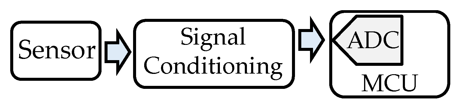
Figure 2.
Paper Organization.

Figure 3.
Classification of reviewed papers.
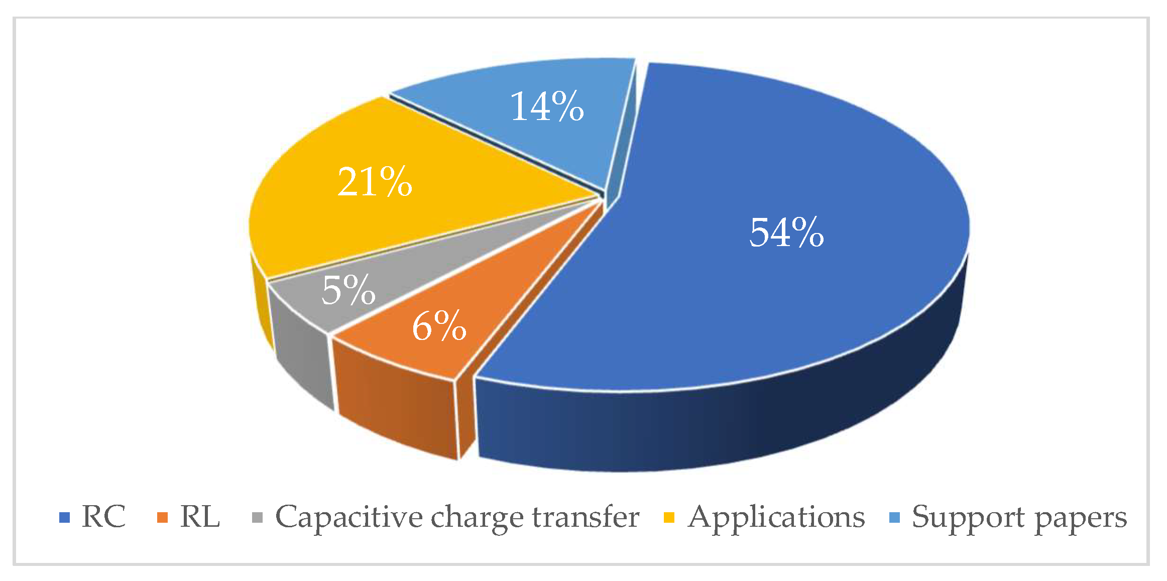
Figure 4.
Scheme of basic DIC and its calibration techniques for resistive, capacitive, and inductive sensors.
Figure 4.
Scheme of basic DIC and its calibration techniques for resistive, capacitive, and inductive sensors.
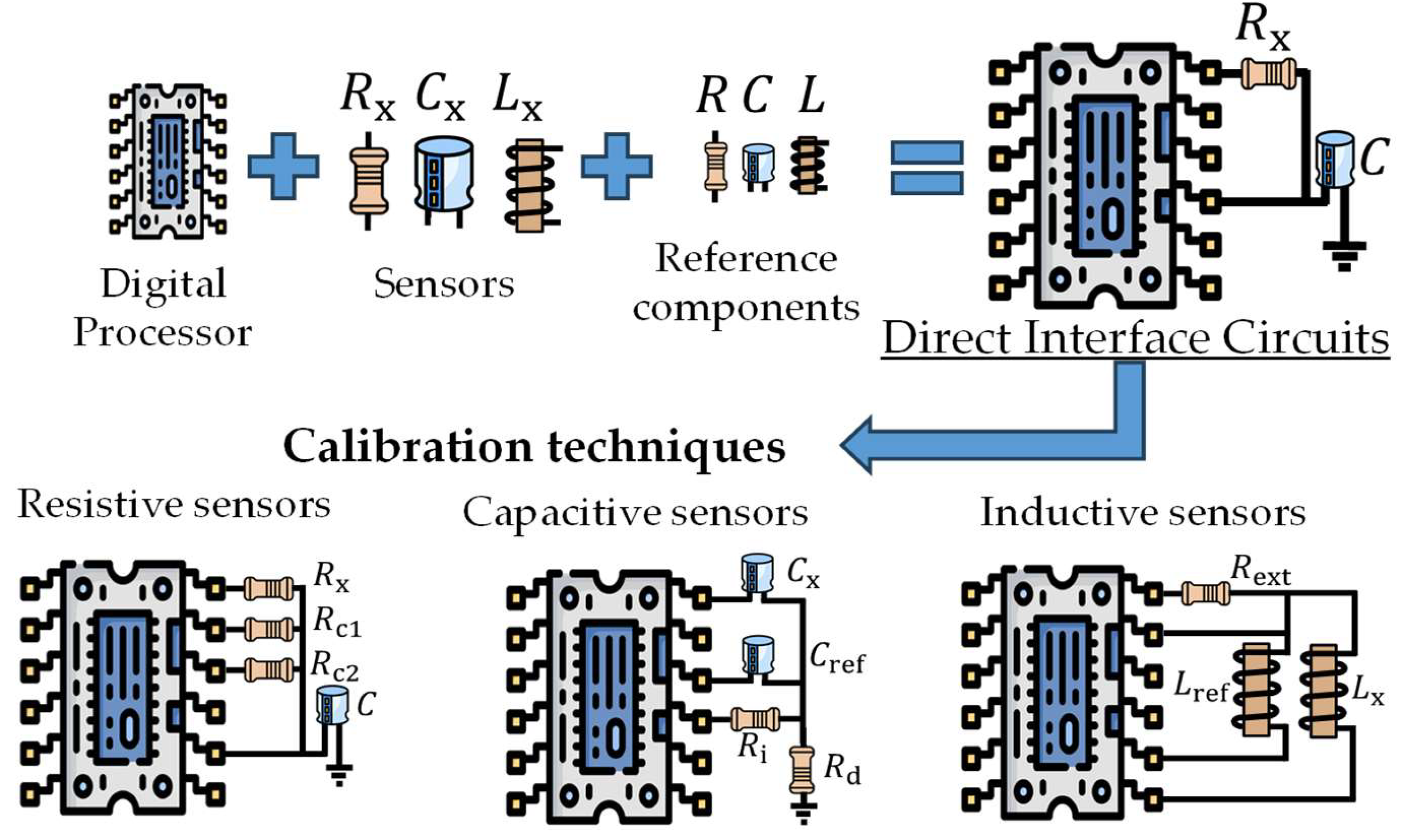
Figure 5.
Resistive sensors: a) simple, b) differential, and c) bridge; capacitive sensor types: d) simple, e) lossy, f) differential, and g) bridge; and inductive sensor types: h) simple, i) differential, j) simple with ferromagnetic core, and k) differential with ferromagnetic core.
Figure 5.
Resistive sensors: a) simple, b) differential, and c) bridge; capacitive sensor types: d) simple, e) lossy, f) differential, and g) bridge; and inductive sensor types: h) simple, i) differential, j) simple with ferromagnetic core, and k) differential with ferromagnetic core.

Figure 6.
Wire-resistance techniques for resistive sensors: a) three-wire resistive sensor, and b) four-wire resistive sensor.
Figure 6.
Wire-resistance techniques for resistive sensors: a) three-wire resistive sensor, and b) four-wire resistive sensor.
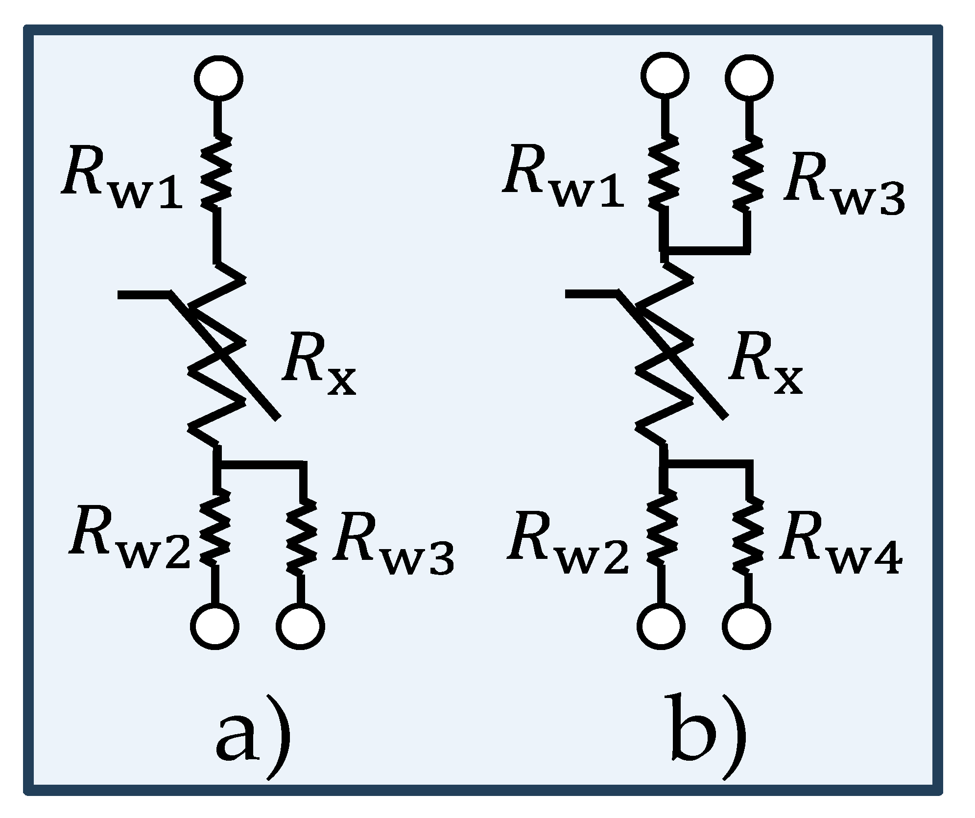
Figure 7.
Time-to-Digital Converter principle.
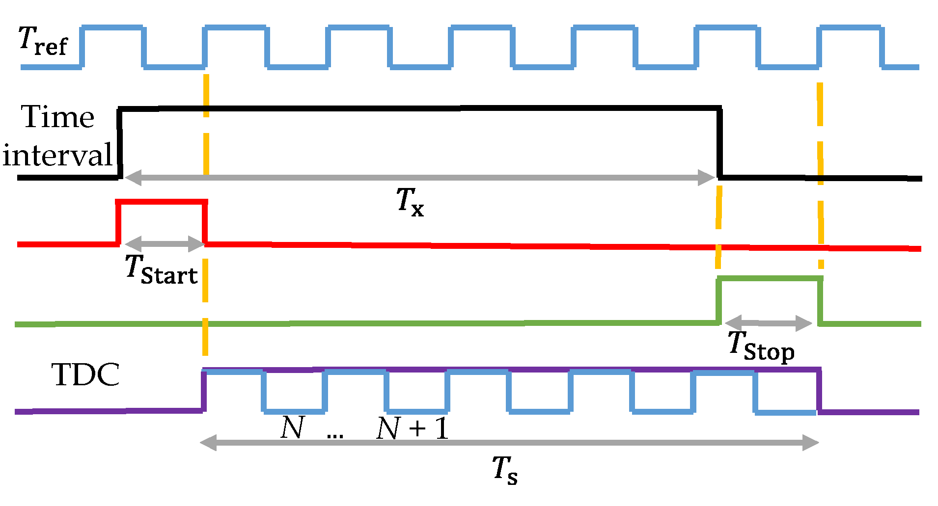
Figure 8.
Basic DIC between resistive sensor and MCU showing charge/discharge timing.
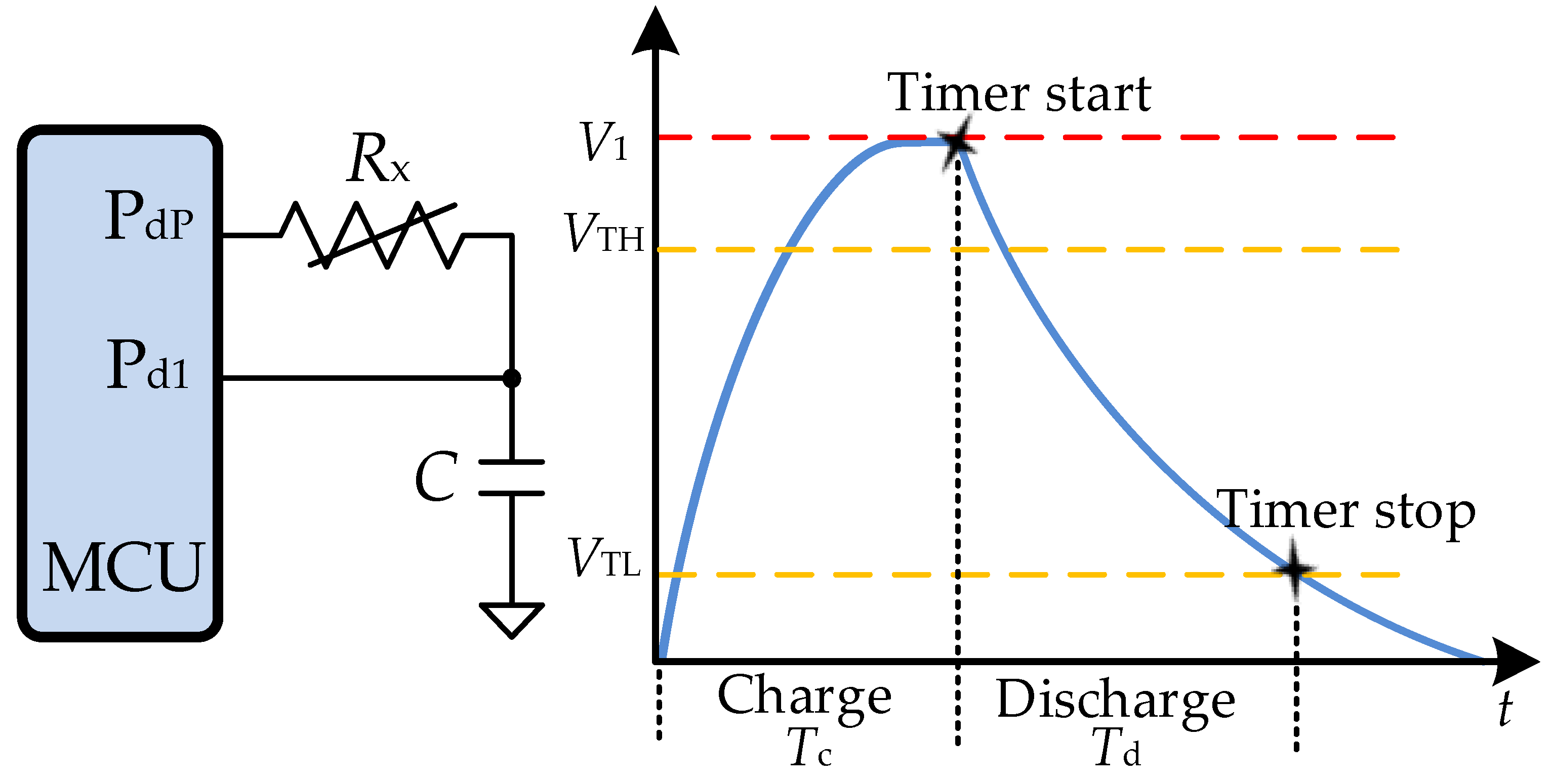
Figure 9.
DIC with resistive sensor using single-point calibration and timing process.
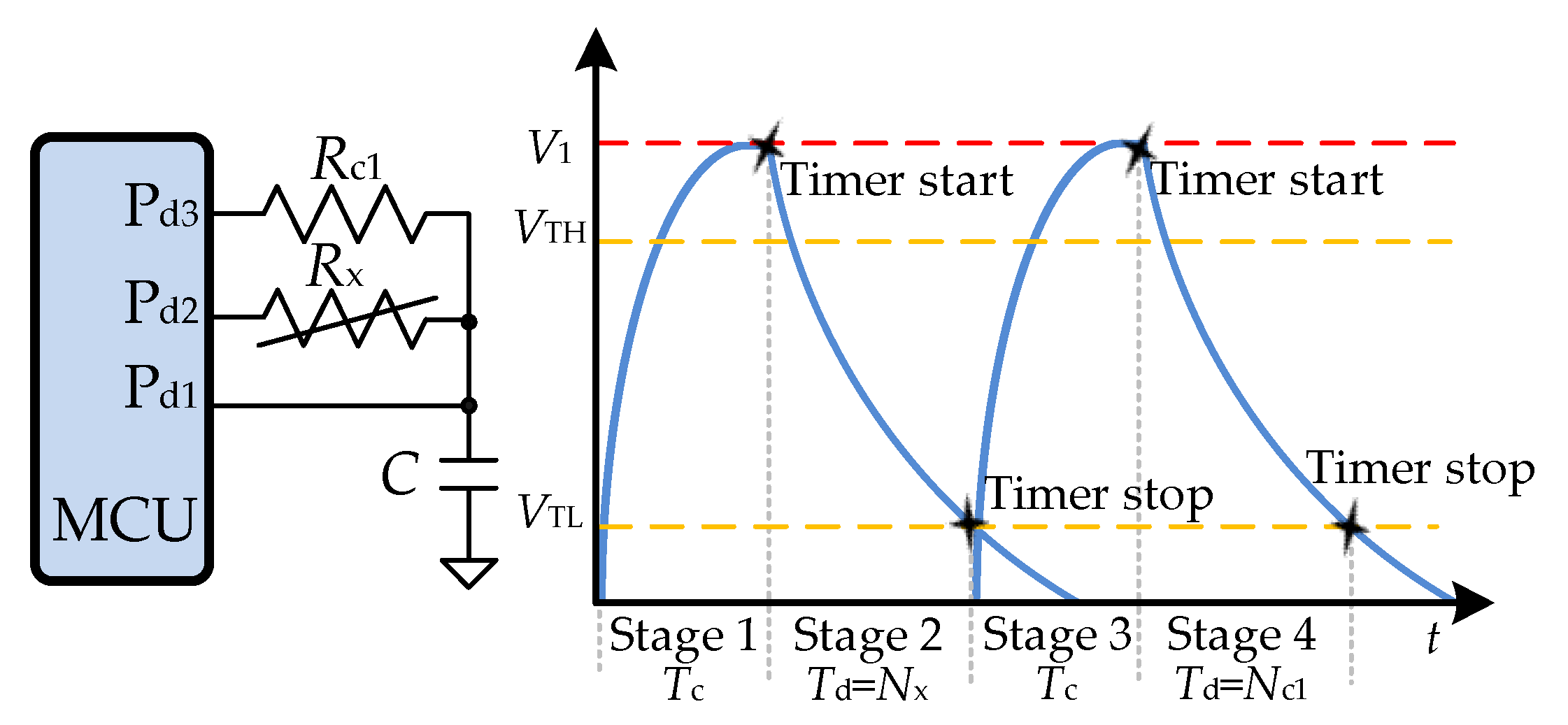
Figure 10.
DIC with capacitive sensor using single-point calibration.
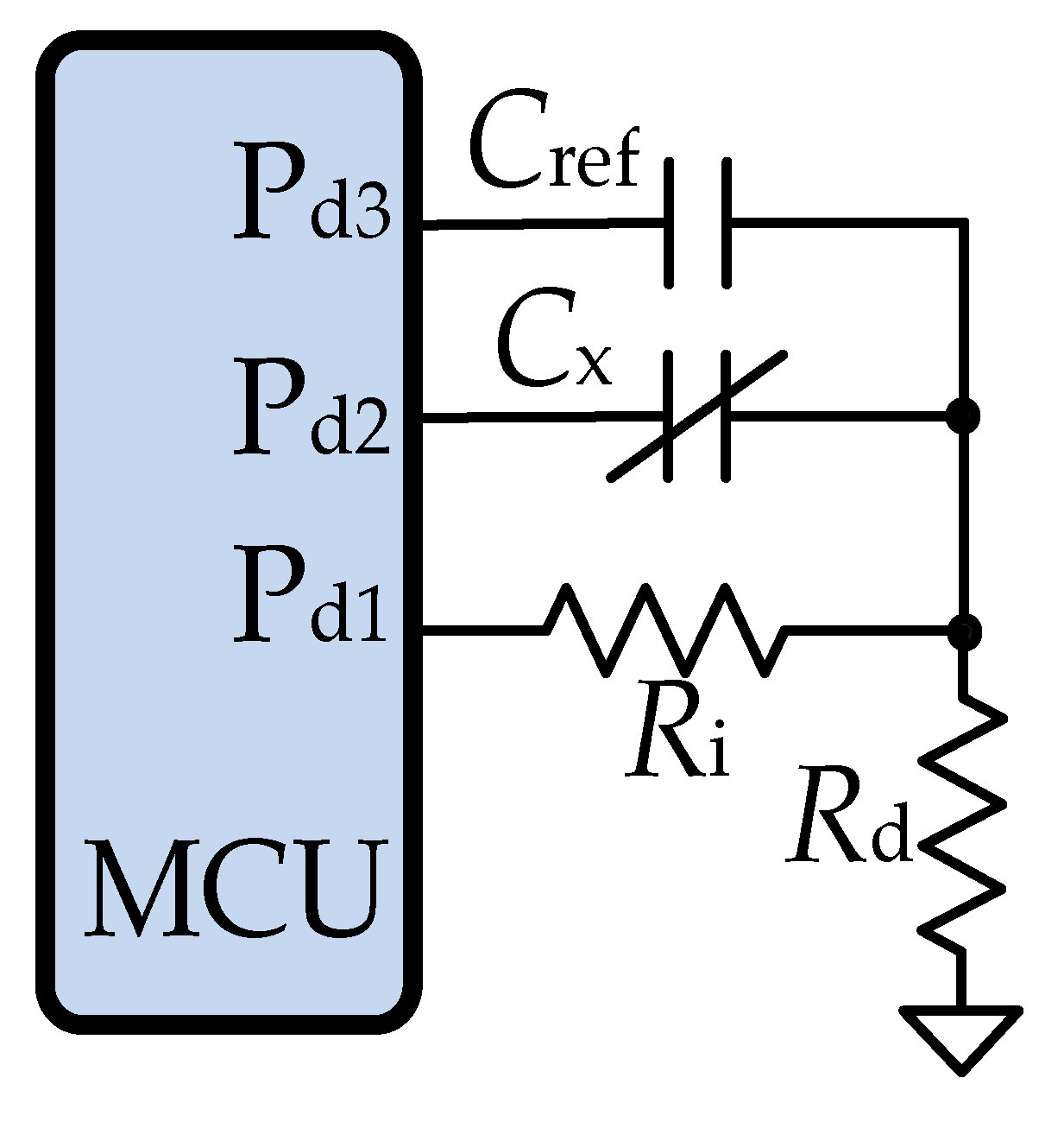
Figure 11.
DIC with resistive sensor using two-point calibration and timing process.
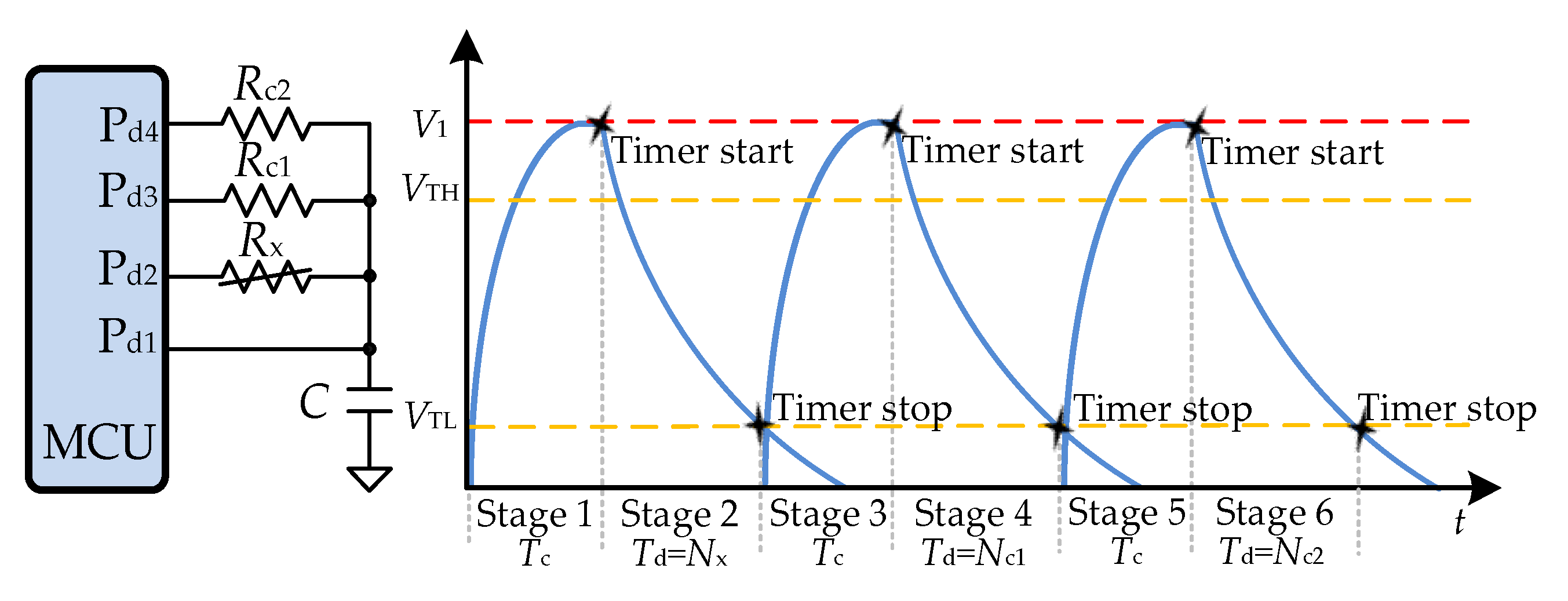
Figure 12.
DIC with resistive sensor using three-point calibration technique.
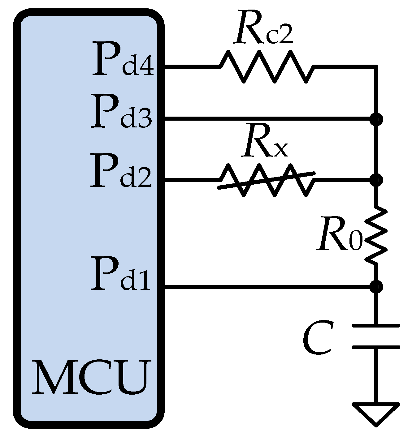
Figure 13.
DIC with inductive sensor using single-point calibration.
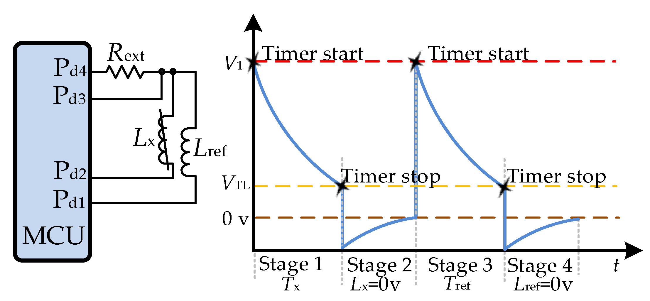
Figure 14.
Capacitance charge transfer technique.
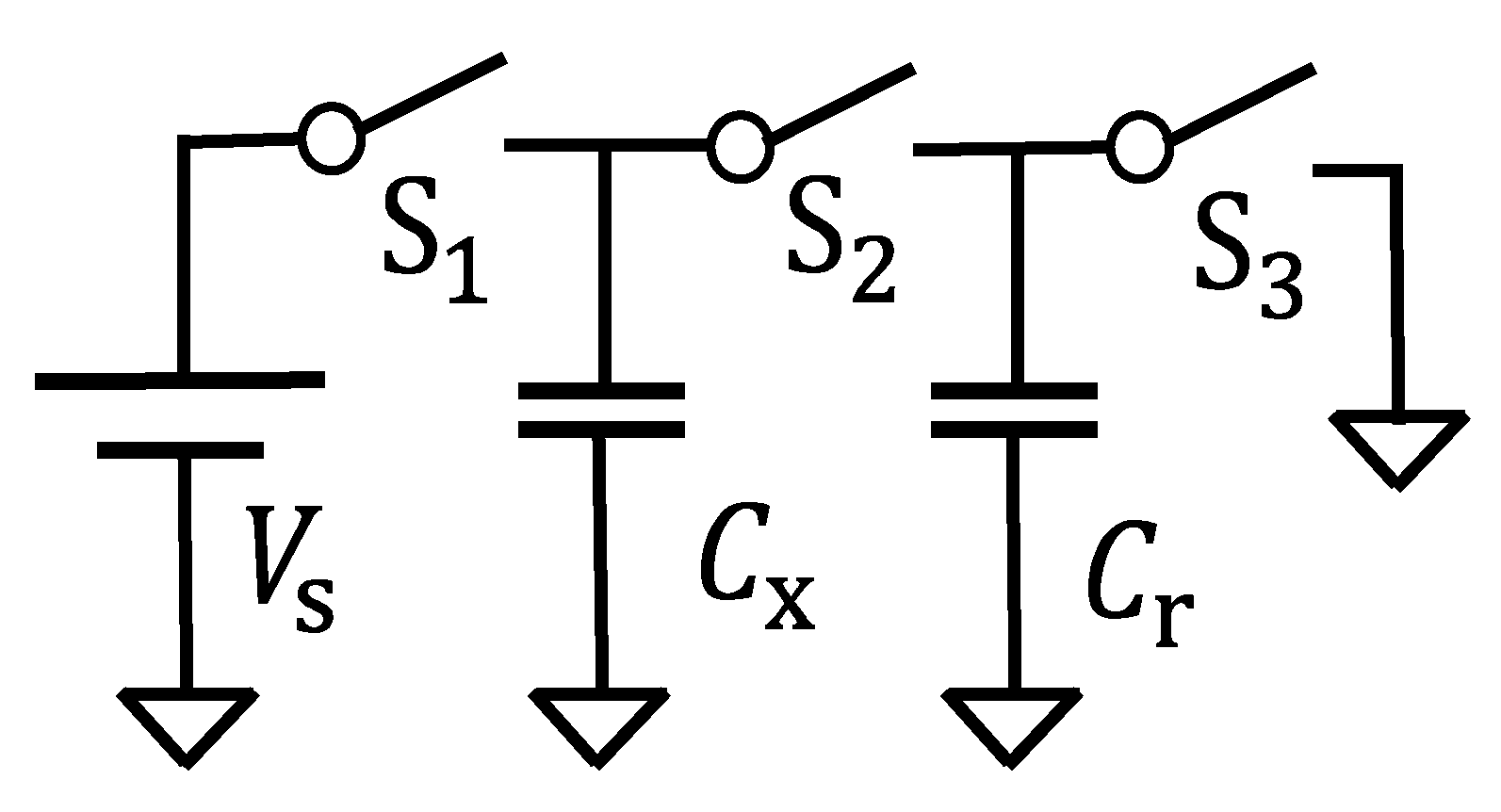
Figure 15.
DIC with capacitive sensor using charge transfer technique.
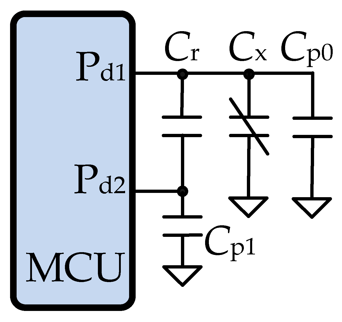
Figure 16.
DIC with charge transfer using the two-point calibration technique.
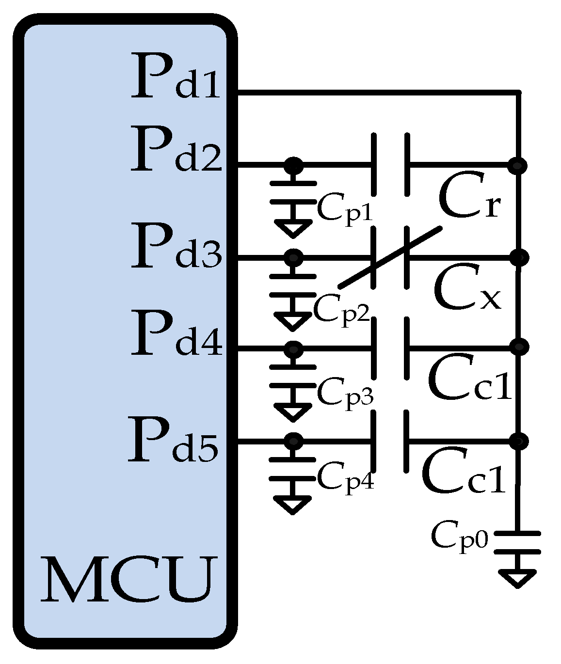
Figure 17.
Percentage contribution area for each DIC configuration studied.
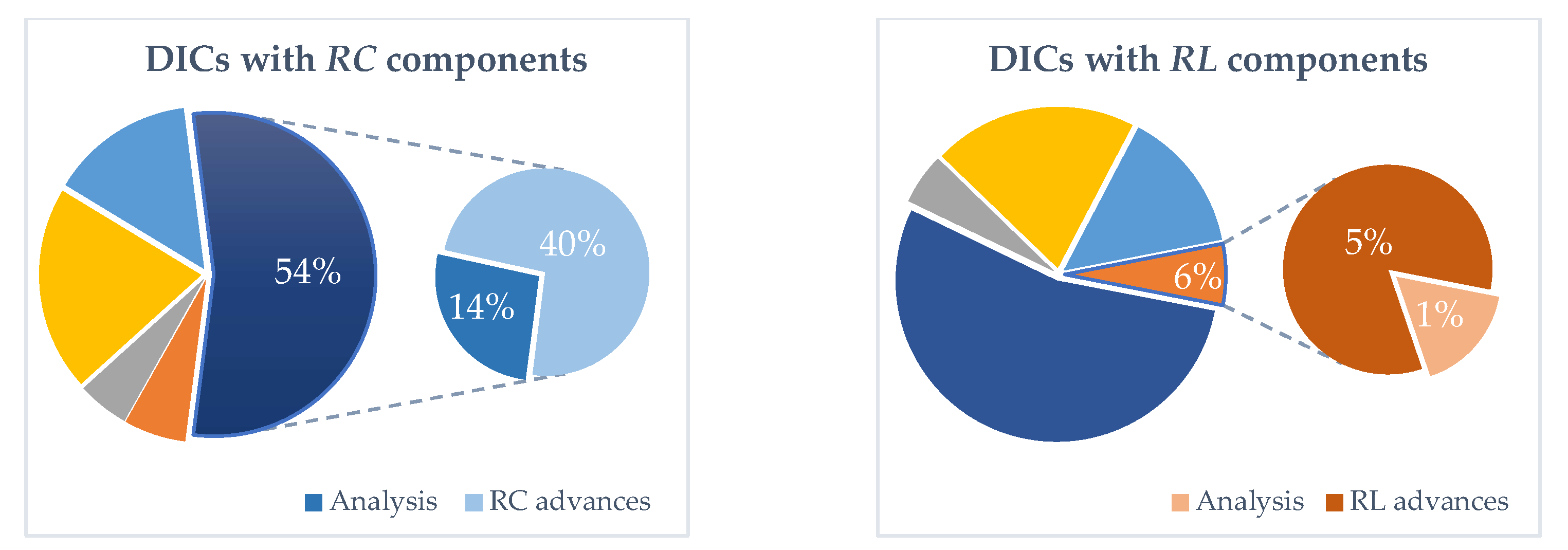
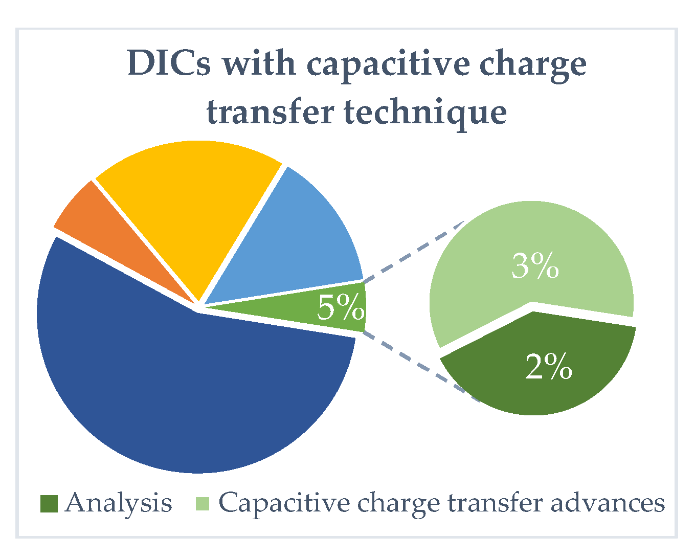
Figure 18.
Applications of DICs by percentage areas.
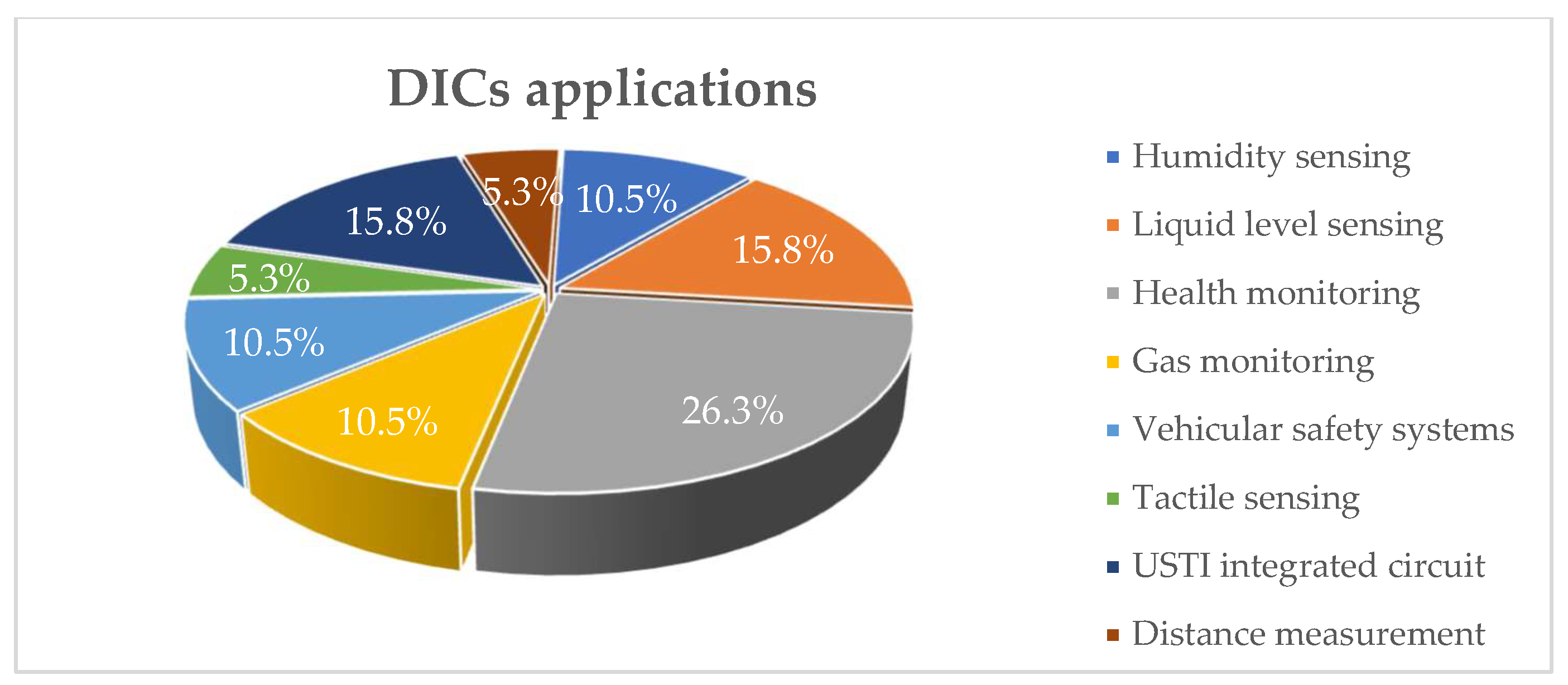

Table 1.
MCU pin configuration and measurement procedure of a resistive sensor.
| Stage | Process | ||
|---|---|---|---|
| 1 | '1' | 'HZ' | |
| 2 | 'HZ', and capture time | '0' |
Table 2.
MCU pin configuration and measurement procedure for single-point calibration of a resistive sensor.
Table 2.
MCU pin configuration and measurement procedure for single-point calibration of a resistive sensor.
| Stage | Process | |||
|---|---|---|---|---|
| 1 | '1' | 'HZ' | 'HZ' | |
| 2 | 'HZ', and capture | '0' | 'HZ' | |
| 3 | '1' | 'HZ' | 'HZ' | |
| 4 | 'HZ', and capture | 'HZ' | '0' |
Table 3.
MCU pin configuration and measurement sequence for single-point calibration of a capacitive sensor.
Table 3.
MCU pin configuration and measurement sequence for single-point calibration of a capacitive sensor.
| Stage | Process | |||
|---|---|---|---|---|
| 1 | '1' | '0' | 'HZ' | |
| 2 | 'HZ', and capture | '0' | 'HZ' | |
| 3 | '1' | 'HZ' | '0' | |
| 4 | 'HZ', and capture | 'HZ' | '0' |
Table 4.
MCU pin configuration and measurement sequence for two-point calibration of a resistive sensor.
Table 4.
MCU pin configuration and measurement sequence for two-point calibration of a resistive sensor.
| Stage | Process | ||||
|---|---|---|---|---|---|
| 1 | '1' | 'HZ' | 'HZ' | 'HZ' | |
| 2 | 'HZ', and capture | '0' | 'HZ' | 'HZ' | |
| 3 | '1' | 'HZ' | 'HZ' | 'HZ' | |
| 4 | 'HZ', and capture | 'HZ' | '0' | 'HZ' | |
| 5 | '1' | 'HZ' | 'HZ' | 'HZ' | |
| 6 | 'HZ', and capture | 'HZ' | 'HZ' | '0' |
Table 5.
MCU pin configuration and measurement sequence for two-point calibration of a capacitive sensor.
Table 5.
MCU pin configuration and measurement sequence for two-point calibration of a capacitive sensor.
| Stage | Process | |||
|---|---|---|---|---|
| 1 | '1' | '0' | 'HZ' | |
| 2 | 'HZ', and capture | '0' | 'HZ' | |
| 3 | '1' | 'HZ' | '0' | |
| 4 | 'HZ', and capture | 'HZ' | '0' | |
| 5 | '1' | 'HZ' | '0' | |
| 6 | 'HZ', and capture | 'HZ' | 'HZ' |
Table 6.
MCU pin configuration and measurement sequence for three-point calibration of a resistive sensor.
Table 6.
MCU pin configuration and measurement sequence for three-point calibration of a resistive sensor.
| Stage | Process | ||||
|---|---|---|---|---|---|
| 1 | '1' | 'HZ' | 'HZ' | 'HZ' | |
| 2 | 'HZ', and capture | '0' | 'HZ' | 'HZ' | |
| 3 | '1' | 'HZ' | 'HZ' | 'HZ' | |
| 4 | 'HZ', and capture | 'HZ' | '0' | 'HZ' | |
| 5 | '1' | 'HZ' | 'HZ' | 'HZ' | |
| 6 | 'HZ', Capture | 'HZ' | 'HZ' | '0' |
Table 7.
MCU pin configuration and measurement sequence for single-point calibration of an inductive sensor.
Table 7.
MCU pin configuration and measurement sequence for single-point calibration of an inductive sensor.
| Stage | Process | ||||
|---|---|---|---|---|---|
| 1 | '1' | 'HZ', and capture | '0' | 'HZ' | |
| 2 | '0' | 'HZ' | '0' | 'HZ' | during |
| 3 | '1' | 'HZ', Capture | 'HZ' | '0' | |
| 4 | '0' | 'HZ' | 'HZ' | '0' | during |
Table 8.
The operational principle of capacitive charge transfer.
| Stage | Process | |||
|---|---|---|---|---|
| 1 | open | open | close | discharge |
| 2 | close | open | open | |
| 3 | open | close | open | charge transfer |
Table 9.
MCU pin configuration and measurement sequence for charge transfer-based estimation of a capacitive sensor.
Table 9.
MCU pin configuration and measurement sequence for charge transfer-based estimation of a capacitive sensor.
| Stage | Process | ||
|---|---|---|---|
| 1 | '0' | '0' | Discharge to |
| 2 | '1' | 'HZ' | |
| 3 | 'HZ', Capture | '0' | Capture of charge cycles |
Table 10.
Summary of digital processors used in DIC implementations, including operating frequency, timer resolution, measuring range, and voltage.
Table 10.
Summary of digital processors used in DIC implementations, including operating frequency, timer resolution, measuring range, and voltage.
| Ref. | Digital processor | Manufacturer | Clock Reference | Timer-counter bits | Time resolution | Supply Voltage (v) | |
|---|---|---|---|---|---|---|---|
| [36,37,38,81,84] | FPGA | Artix 7 XC7A35T | Xilinx | 50 MHz | 18 bits | 20 ns | 3.3 |
| [39,40,41] | FPGA | Spartan 6 (XC6SLX25-3FTG256) | Xilinx | 50 MHz | 14 bits | 20 ns | 3.3 |
| [42,43,44] | FPGA | Spartan 3 (XC3S50AN-4TQG144C) | Xilinx | 50 MHz | 14 bits | 20 ns | 1.2 - 3.3 |
| [45,46] | MCU | ATXmega32A4 | Atmel | 16 MHz | 16 bits | 62.5 ns | 3.3 |
| [21,47,51,83] | MCU | ATmega328P | Atmel | 16 MHz | 16 bits | 62.5 ns | 3.3 – 5 |
| [16,18,19,20,52,76,78,82] | MCU | AVR ATtiny2313 | Atmel | 20 MHz | 16 bits | 50 ns | 5 |
| [15,53,54,55] | MCU | AVR AT90S2313 | Atmel | 4 MHz | 16 bits | 250 ns | 5 |
| [22] | MCU | SAM3X8E ARM Cortex-M3 | Atmel | 84 MHz | 32 bits | Prescaler (11.9 ns × 2) = 23.8 ns | 3.3 |
| [15,31,56,57,58] | MCU | PIC16F873 | Microchip | 20 MHz | 16 bits | 200 ns | 5 |
| [42] | MCU | PIC16LF1559 | Microchip | 32 MHz | 16 bits | 125 ns | 3.3 |
| [59] | MCU | PIC16F876 | Microchip | 20 MHz | 16 bits | 200 ns | 5 |
| [21] | MCU | PIC16F877A | Microchip | 5 MHz | 16 bits | 800 ns | 5 |
| [60,90] | MCU | PIC16F877A | Microchip | 20 MHz | 16 bits | 200 ns | 5 |
| [61] | MCU | PIC18F45K22 | Microchip | 20 MHz | 16 bits | 200 ns | 5 |
| [34] | MCU | PIC12C508 | Microchip | not specified | 8 bits | not specified | 5 |
| [33,35,62,63] | MCU | PIC16F84A | Microchip | 4 MHz | 16 bits | 1 µs | 5 |
| [89] | MCU | PIC18F4680 | Microchip | 8 MHz | 16 bits | 125 ns | 5 |
| [64] | MCU | MSP430F1471 | Texas Instruments | 32 KHz | 16 bits | 7 MHz (DCO) =142 ns | 3.3 |
| [65] | MCU | MSP430F1471 | Texas Instruments | 8 MHz | 16 bits | 125 ns | 3.3 |
| [66,67,68] | MCU | MSP430F123 | Texas Instruments | 8 MHz | 16 bits | 125 ns | 3.3 |
| [17] | MCU | MSP430F123 | Texas Instruments | 4 MHz | 16 bits | 250 ns | 3.3v |
| [69] | MCU | MSP430F2274 | Texas Instruments | 8 MHz | 16 bits | 125 ns | 3.3 |
| [70] | MCU | STM32F401CBU6 | ST Micro | 48 MHz | 16 bits | 20.83 ns | 2.7 - 3.6 |
| [71] | MCU | D1 mini ESP32 | Espressif Systems | 80 MHz | 64 bits | 12.5 ns | 3.3 |
| [72] | MCU | C8051F040 | Silicon Labs | 25 MHz | 16 bits | 40 ns | 2.7 - 5.6 |
| [73] | FPGA | Cyclone III EP3C10 | Intel | 48 MHz | 16 bits | 20 ns | 3.3 |
Table 11.
Summary of DIC implementations with RC components for resistive and capacitive sensors.
| Ref. | Sensor type | DIC components | Keywords | Operative parameters reported |
|---|---|---|---|---|
| [76] | Four-wire resistive sensors | Three resistors, a capacitor, a switch, a sensor, and MCU. | A direct approach for interfacing four-wire resistive sensors. |
|
| [78] | Three-wire resistive sensors | Three resistors, a capacitor, a sensor, and MCU. | A DIC for Three-Wire connected resistive sensors |
|
| [81] | Simple resistive sensors | Two resistors, a capacitor, a sensor, and FPGA. | Two-Measurement Method (TMM) for resistive sensors affected by lead-wire resistances. |
|
| Three resistors, a capacitor, a sensor, and FPGA. | Improved Method (IM) for resistive sensors affected by lead-wire resistances. |
|
||
| [82] | Non-linear resistive sensors, such as thermistor B57164K from TDK | Three resistors, a capacitor, a sensor, and MCU. | DIC for non-linear resistive sensors. |
|
| [36] | Differential resistive sensors | Two capacitors, a resistor, a sensor, and FPGA. | Proposal of a simple digital readout DIC for differential resistive sensors. |
|
| Differential capacitive sensors | Two resistors, a capacitor, a sensor, and FPGA. | Proposal of a simple digital readout DIC for differential capacitive sensors. |
|
|
| [16] | Differential resistive sensors for linear position, angular position, pressure sensors, or level sensors. | Two resistors, a capacitor, a sensor, and MCU. | Interfacing differential resistive sensors with DIC. |
|
| [19] | Differential capacitive sensors, as the accelerometer SCG10Z-G001CC from VTI Technologies. | Two resistors, a sensor, and MCU. | Interfacing differential capacitive sensors with DIC. |
|
| [37] | Simple resistive sensors include resistance temperature detectors (RTD), gas, force, or humidity sensors. | Two capacitors, a sensor, and FPGA. | Proposal of a Two-Capacitor Interface (TCI) to simplify resistive sensor readout |
|
| Two resistors, a sensor, and FPGA. | Proposal of a Single-Capacitor Interface (SCI) to simplify resistive sensor readout |
|
||
| [38] | Simple capacitive sensors, such as liquid level, pressure, strain, and humidity sensors. | Two resistors, a sensor, and MCU. | Proposal of a new DIC to simplify the capacitive sensor |
|
| [84] | Capacitive sensors | Two resistors, an operational amplifier, a sensor, and FPGA. | DIC for capacitive sensors affected by parasitic series resistances. |
|
| [15] | Simple resistive sensors, as Pt1000 RTD sensors. | Two resistors, a capacitor, a sensor, and MCU. | Study of the accuracy and resolution of a DIC for resistive sensors. |
|
| [39] | Simple resistive sensors, focused on tactile sensors. | Four resistors, two capacitors, a sensor, and FPGA. | Proposal of a Two-Capacitor Direct Interface Circuit (TCDIC) to enhance the measurement of resistive sensors |
|
| [40] | Simple resistive sensors include thermistors, strain gauges, pressure sensors, and biomedical sensors. | Three resistors, two capacitors, a sensor, and FPGA. | Proposal of a Quantization Error Reduction Method (QERM) to reduce quantization errors when measuring low resistance values. |
|
| [41] | Simple resistive sensors. | Three resistors, a capacitor, a sensor, and FPGA. | Proposal to reduce time measurement in DIC for resistive sensors. |
|
| [46] | Simple capacitive sensors, as capacitive relative humidity (RH) sensors. | A resistor, an analog comparator, a DAC, a sensor, and MCU. | Proposal a measurement method based on a versatile DIC with internal MCU peripherals. |
|
| [42] | Simple resistive sensors include temperature, gas, anemometers, and tactile sensors. | Four resistors, a capacitor, a sensor, and MCU. | MCU proposes an Improved Calibration Method (ICM) to provide more accurate measurements and reduce relative errors. |
|
| Four resistors, a capacitor, a sensor, and FPGA. | FPGA proposes an Improved Calibration Method (ICM) to provide more accurate measurements and reduce relative errors. |
|
||
| [83] | Capacitively-coupled resistive sensors. | A reference resistor, a capacitor, an operational amplifier, a capacitively-coupled resistive sensors, and a MCU. | A first approach of a DIC for Capacitively-Coupled Resistive Sensors. |
|
| [43] | Simple resistive sensors include thermistors, gas detection, magneto-resistive, and tactile sensors. | Two resistors, a capacitor, a sensor, and FPGA. | Proposal of two fast calibration methods to improve faster, more efficient, and more accurate sensor data acquisition. |
|
| [85] | Resistive sensors | Three resistors, a capacitor, a sensor, and FPGA. | Quasi single point calibration method for high-speed measurements. |
|
| [45] | Simple resistive sensors, as thermistors or strain gauges. | A resistor, a capacitor, an ADC, an analog comparator, two MOSFETs, a sensor, and MCU. | The time-domain measurement method for resistive sensors is based on a versatile DIC with external components. |
|
| Simple capacitive sensors, such as touch sensing, pressure sensing, liquid level measurement, or proximity sensors. | The time-domain measurement method for capacitive sensors is based on a versatile DIC with external components. |
|
||
| [47] | Simple resistive sensors include RTD, thermistors, LDRs, strain gauges, gas sensors, and piezoresistive sensors. | Two resistors, a capacitor, an analog comparator, 2 diodes, a sensor, and MCU. | Propose a DIC that minimizes measurement errors due to lead wire resistance variations and temperature compensation. |
|
| [64] | Simple resistive sensors | Two resistors, a capacitor, a sensor, and MCU. | Proposal for a low-power consumption DIC through a design guide for the selection of optimal parameters related to the measurement setup for resistive sensors |
|
| [65] | Simple capacitive sensors | A resistor, a sensor, and MCU. | Proposal of calibration-less DIC |
|
| [52] | Simple resistive sensors | A resistor, a capacitor, a sensor, and MCU. | Analysis for optimizing DICs to enhance their power consumption, particularly for battery-operated applications. |
|
| Simple capacitive sensors | Two resistors, a sensor, and MCU. |
|
||
| [20] | Lossy capacitors, as P14–Rapid capacitive humidity sensor. | Two resistors, a capacitor, a sensor, and MCU. | Proposal DIC for lossy capacitance sensors. |
|
| [66] | Simple resistive sensors, such as Pt1000 temperature sensors or magneto-resistive sensors. | Two resistors, a capacitor, a sensor, and MCU. | Proposal to improve traditional DIC performance using a Vernier technique. |
|
| [17] | Bridge type resistive sensors, as the full-bridge HMC1052 sensor, an Anisotropic Magneto-resistive (AMR) sensor or the half-bridge AAH002 sensor, a Giant Magneto-resistive (GMR). | A resistor, a capacitor, a sensor, and MCU. | A DIC proposal to linearize resistive sensor bridges. |
|
| [56] | Bridge type resistive sensors, as MPXV53GC7U piezoresistive pressure sensors. | A resistor, a capacitor, a Schmitt trigger, a sensor, and MCU. | A simple and efficient DIC proposal for piezoresistive pressure sensors |
|
| [18] | Simple capacitive sensors, like Philips H1 Sensor and Humirel HS1101 Sensor. | Two resistors, a capacitor, a sensor, and MCU. | A DIC proposal for capacitive humidity sensors. |
|
| [31] | Simple capacitive sensors. | A resistor, a capacitor, a sensor, and MCU. | A low-cost DIC proposal for low-value capacitive sensors. |
|
| [88] | Simple resistive sensors | Two resistors, a capacitor, a sensor, and MCU. | One point auto-calibration technique sensor interface |
|
| [91] | Resistive sensor arrays | A sensor array, a capacitor, and a FPGA | DIC for resistive sensor arrays: resolution analysis. |
|
| [57] | Analysis of power-supply interference effects on DIC sensor-MCU. | |||
| [53] | Effective number of resolution bits in direct sensor-to-microcontroller interfaces. | |||
| [54] | Uncertainty reduction techniques in microcontroller-based time measurements. | |||
| [44] | Innovative capture modules for DIC sensor-FPGA. | |||
| [55] | Measurement error analysis and uncertainty reduction for period and time interval-to-digital converters based on MCU. | |||
Table 12.
Summary of DIC implementations with RL components for inductive sensors.
| Ref. | Sensor type | DIC components | Keywords | Operative parameters reported |
|---|---|---|---|---|
| [21] | Simple inductive sensors for displacement or position measurement, and inductive pressure or temperature sensors. | A resistor, an inductor, a sensor, and MCU. | A DIC proposal for low-pass filter (LPF) inductive sensors. |
|
| [60] | Simple inductive sensors. | A resistor, an inductor, four MOSFETs, a sensor, and MCU. | Improving the resolution in a DIC for LPF and high-pass filter (HPF) inductive sensors. |
|
| [22] | Differential inductive sensors include linear variable differential transformer (LVDT) and differential variable reluctance transducer (DVRT). | A resistor, an analog comparator, an inductor, two diodes, a sensor, and MCU. | A simple and effective digitizer designed for differential variable inductive and reluctance sensors. |
|
| [45] | Simple inductive sensors | A resistor, a capacitor, an ADC, an analog comparator, two MOSFET, a sensor, and MCU. | Time-domain measurement method for inductive sensors based on a versatile DIC with external components |
|
| [48] | Simple inductive sensors | A resistor, an inductor, an analog comparator, a sensor, and MCU. | DIC proposal for resolution enhancement for inductive sensors. |
|
| [49] | Differential inductive sensors, like the SM260.100.2 inductive sensor from Schreibe, for linear displacement. | A resistor, a sensor, and MCU. | DIC proposal for differential inductive sensors. |
|
| [50] | Investigation of errors in the microcontroller interface circuit for the mutual inductance sensor. | |||
Table 13.
Summary of DIC implementations using capacitive charge transfer technique.
| Ref. | Sensor type | DIC components | Keywords | Operative parameters reported |
|---|---|---|---|---|
| [34] | Simple capacitive sensors, fluid levels monitoring. | A capacitor, a diode, an inductor, a sensor, and MCU. | Wireless liquid level sensing for restaurant applications with charge transfer technique. |
|
| [33,35] | Simple capacitive sensors. | Two capacitors, a sensor, and MCU. | DIC proposal for simple capacitive sensors with charge transfer technique. |
|
| [62] | Differential capacitive sensors measure various physical quantities, such as linear or angular position, displacement, pressure, and force. | Two capacitors, a sensor, and MCU. | DIC proposal for differential capacitive sensors with charge transfer technique. |
|
| [63] | Simple resistive sensors, such as NTC Thermistors or LDR. | Three resistors, two capacitors, a sensor, and MCU. | DIC proposal for simple resistive sensors with charge transfer technique. |
|
| [58] | Analysis of capacitive interferences in DIC with the transfer charge technique. | |||
Table 14.
Summary of sensor interfaces and applications reported in the reviewed literature.
| Ref. | Sensor type | Application |
|---|---|---|
| [70] | Light emitting diodes (LEDs) for light sensing. | Monitoring vegetation health and density |
| [71] | Force sensing resistor | Heart rate measurement. |
| [67] | Force sensing resistor | Seat occupancy detection system |
| [51] | Magneto-resistive sensor | Measuring dynamic signals such as Electrocardiogram (ECG) signals |
| [61] | Metal oxide semiconductor (MOS) gas sensor | Gas sensors are used to monitor and discriminate between different gases. |
| [87] | Chemoresistive gas sensor | Gas sensor to estimate CO and NO2. |
| [68] | Nasal thermistor and piezoresistive sensor | Application in clinical and home settings for respiratory rate detection systems for health monitoring. |
| [72] | Grounded cylindrical capacitive sensor | Water level monitoring for tanks |
| [73] | LEDs for a photoplethysmography (PPG) sensor | Oximeter for blood oxygen saturation monitoring |
| [69] | Giant Magneto-resistive (GMR) sensor and an LDR | Wireless magnetic sensor node for vehicle detection |
| [18] | Capacitive humidity sensor | Humidity sensing for industrial automation |
| [59] | Grounded capacitive sensor | Liquid-level measurement for industrial processes |
| [34] | Capacitive sensor | Wireless liquid level sensing |
| [21] | Inductive sensor | Displacement and position measurement. |
| [22] | Differential inductive sensors | Linear variable differential transformer (LVDT), and differential variable reluctance transducer (DVRT). |
| [89] | Piezoresistive tactile sensors | Humanoid robots, industrial robotics, medical prosthetics and rehabilitation devices |
| [90] | RFID capacitive humidity sensor | RFID labels for wireless sensing, such as food traceability and industrial monitoring |
| [93,94,95] | Universal Sensors and Transducers Interface circuit (USTI) |
An integrated circuit for resistive, resistive-bridge, and capacitive sensors, such as, measurement of gases, humidity, temperature sensors, pressure sensors, displacement sensors and biomedical devices. |
| [96] | Ultrasonic smart sensors | Distance measurement with a USTI integrated circuit for distance measurements, tank level measurements, object detection and monitoring, garage parking assistance, and motion detection systems. |
Table 15.
DICs advance over the years.
| Decade | Percentage | Contribution |
|---|---|---|
| 1990s | 3% | Basic concepts, application notes, and simple DICs; publications specifically focused on detailed interface designs. |
| 2000s | 15.5% | Operative principles of DIC, significant improvement papers, such as calibration techniques to increase accuracy and reduce uncertainty errors, and analysis papers of key parameters. |
| 2010s | 45% | Most advances in compact circuits, error mitigation techniques, improved calibration methods, low-power solutions, and DIC applications. |
| 2020s | 36.5% | Novel sensor interfaces for non-linear sensors, correction of parasitic resistance effects with wire-resistance techniques for resistive, capacitive, and remote sensors. |
Table 16.
Summary of key DIC applications identified in the reviewed literature.
| Category | Key elements | Advances | Challenges | Perspectives and recommendations |
|---|---|---|---|---|
| RC circuits | Resistors, capacitors, MCU or FPGA | Low cost, compact design, energy-efficient, and simple implementation. | Enhancing accuracy and resolution, reducing measurement time, and minimizing quantization errors. | Investigate advanced calibration strategies and optimize power consumption. |
| RL circuits | Inductors, resistors, and MCU | Energy efficiency and accurate inductance measurements. | Addressing issues related to noise sensitivity and prolonged measurement time. | Develop strategies for noise immunity, faster measurement processes, and optimized circuit topologies. |
| Capacitive charge transfer | Capacitors, resistors, and MCU | Compact and efficient measurement, robust performance under controlled conditions | Sensitivity to parasitic capacitances and systematic measurement errors | Apply enhanced multi-point calibration methods to increase reliability and reduce systematic errors. |
| Digital processors | MCU or FPGA | Flexible integration, broad commercial availability, and adaptability for various applications. | Resolution variability is dependent on internal timers and power management challenges. | Evaluate trade-offs between energy consumption and performance and adjust operating frequencies according to the application. |
| Calibration techniques | Single-point, two-point, and three-point calibration. | Improved accuracy, compensating for systematic measurement errors and enhancing reliability. | Increased complexity and higher power consumption with advanced techniques. | Explore hybrid and adaptive calibration methods tailored to sensor characteristics and application environments. |
| Differential and bridge-type sensors | Resistive, capacitive, and inductive differential sensors. | Improved precision through reduced common-mode noise and increased reliability. | Higher complexity and cost in design and implementation | Develop innovative DICs with compensation methods to mitigate environmental effects and parasitic influences. |
Disclaimer/Publisher’s Note: The statements, opinions and data contained in all publications are solely those of the individual author(s) and contributor(s) and not of MDPI and/or the editor(s). MDPI and/or the editor(s) disclaim responsibility for any injury to people or property resulting from any ideas, methods, instructions or products referred to in the content. |
© 2025 by the authors. Licensee MDPI, Basel, Switzerland. This article is an open access article distributed under the terms and conditions of the Creative Commons Attribution (CC BY) license (http://creativecommons.org/licenses/by/4.0/).
Copyright: This open access article is published under a Creative Commons CC BY 4.0 license, which permit the free download, distribution, and reuse, provided that the author and preprint are cited in any reuse.


