
Submitted:
16 May 2025
Posted:
16 May 2025
You are already at the latest version
Abstract
Power Plant Controller (PPC) is used to control the individual inverters in the RE plant based on the grid operator requirements. The real and reactive power set points of individual inverters are decided by PPC based on the voltage and frequency parameters at the Point of Connection/Interest (POC/I). The delay between the instant of measurements at POI and the corresponding command signal from PPC reaching inverters may exist due to communication delays, poor PQ meter sampling rates, and inverter polling rates. Due to the same reasons, the inverters respond to the changes in grid parameters with the corresponding delays. These delays can result in oscillations as each plant responds differently to changes in its POI voltage. Such delays can amplify certain oscillation modes as the PPC attempts to respond to voltage fluctuations. This paper analyzes the effect of PPC on voltage oscillations at the POI of the PV plant. A hardware-in-loop simulation study is done where the solar power plant is modelled in a Real-Time Digital Simulator (RTDS), and PPC hardware controls the plant model. The study is carried out on the actual PPC hardware, being developed for deployment in a renewable energy plant. The paper gives insights into the effect of PPC settings on the voltage oscillations in the PV power plant.
Keywords:
power plant controller
; solar power plant
; voltage oscillations
; ride through
; droop control
I. Introduction
The Government of India aims to establish 500 GW of non-fossil fuel generation capacity by 2030 and achieve net zero emissions by 2070[1]. However, as renewable energy (RE) generation increases, ensuring grid reliability poses several challenges. Renewable generation, primarily from wind and solar resources, is getting connected to pooling stations in a concentrated manner in India, i.e., in the size of around 3-5 GW, generation is pooled at one particular substation. Many of these pooling stations do not have synchronous machine connectivity, resulting in a weak grid. In those regions with high renewable penetration, such as the Rajasthan RE complex in India (Bhadla-Fatehpur-Bikaner areas), there have been frequent grid disturbances, including multiple instances of voltage oscillations [2].
From mid-December 2022 through November 2024, several voltage oscillations were observed in these areas. These oscillations, mainly in voltage and reactive power, sometimes reached magnitudes of 0.1 p.u., causing voltage fluctuations ranging from 380 kV to 420 kV in the 400 kV grid. Figure 1 shows an example of oscillation observed at 400kV Fatehgarh-2 pooling station(India) on 30th September 2024. These oscillations were primarily observed in voltage and reactive power. Some of these oscillations have resulted in generation loss (even to the order of 7GW) and line tripping as their intensity increases during transient disturbances in the grid [2]. In all these events, there were no triggering events in the grid, such as reactor switching, line charging, etc., that could be considered as the cause of oscillations.
II. Analysis of Voltage Oscillations
Identifying the causes of these oscillations is critical to maintaining grid stability and preventing generation loss. The PMU plot of a PV plant during such oscillation is shown in Figure 2. From the PMU data analysis, it is observed that some of the PV plants inject reactive power with considerable delay, which results in the injection of reactive power in phase with the voltage oscillations thereby amplifying them. The oscillations subsided when some plants were kept in fixed reactive power control mode. The preliminary analysis shows that one of the reasons for these voltage oscillations is the delays associated with PPCs, as the real and reactive power command from the PPC reaches the inverter in some of the RE plants after considerable time delays associated with the Power Plant Controller. These time delays amplify some of the oscillation modes. In this paper, a detailed analysis of oscillation due to PPC delay is done through hardware in-loop simulation of PPC hardware.
III. Power Plant Controller
The simplified block diagram of the PPC is shown in Figure 3. The PQ meter provides active power, reactive power, frequency and voltage measurements (P, Q, f, V) at the plant terminal to the PPC. The PPC calculates the required real and reactive power that needs to be injected into the POI based on the operational mode. The operational mode, droop settings (dead band, droop gain, offset) and the corresponding reference values (Pref, Qref, Vref, fref) are provided to the PPC from the SCADA HMI. In the power factor control mode, the PPC generates a reactive power reference based on the p.f. reference and active power reference value. The voltage magnitude signal error is given to the PI controller in voltage control mode to get the reactive power reference.
The reactive power output of the plant in Q-V droop control mode is decided by the droop gain, dead band and offset of the plant as illustrated in Figure 3. For example, a plant with 4% droop and 1% dead band (with zero offsets) may vary its reactive power to 100 per cent of plant capacity for a change of 4% of its POI voltage from its reference value. However, the reactive power of the RE plants is usually limited to 33% of the plant capacity, and the support from the individual inverters is usually limited to 60% of the inverter capacity.
IV. Signal Delays in the Power Plant Controller
The reactive power injection by each RE plant is controlled by its PPC configuration. The RE plant often has multiple plants commissioned at various times, each with different PPCs, PQ meters, and communication protocols. The PPCs manage the power output of individual inverters in an RE plant, and any delay in their response to grid changes can induce oscillations as well as amplify the existing oscillations in the grid. These delays may stem from the PPC design itself or from limitations in the communication network, which takes the signals from the PQ meter to the PPC and sends the control commands from the PPC to the inverters. Low sampling rates in PQ meters and reduced polling rates for inverters also contribute to these delays. PQ meter has different registers for processing fast and slow data. Fast data channels can transmit data within 10-20 ms, whereas slower channels can take between 250 ms and 1 second. Many older plants have PQ meters that operate only on slow channels, resulting in expected delays of at least 250ms before the PPC receives data from the PQ meter, Figure 4. After receiving this data, the PPC requires an additional 10-20ms to process it and provide the setpoints to the inverters. The PPC sends active (Piref ) and reactive (Qiref ) power commands through the communication network, with delays influenced by the protocol used, such as MODBUS or IEC 61850. The MODBUS communication protocol is slower than IEC 61850 and thus increases communication delay. Due to polling rate limitations, inverters cannot continuously receive updated commands from the PPC. Typical polling rates range from 200 ms to 1 second, restricting the frequency of PPC commands to the inverters. This variability in response times in different plants results in each plant responding differently to voltage changes, which can exacerbate oscillations in the grid and impact grid stability.
V. Effect of PPC Delay in Voltage Oscillations
The RE-penetrated grid generally has low short circuit strength and thus forms a weak grid. According to CEA standards, RE plants must provide 0.33 p.u. of reactive power while delivering 1 p.u. of active power [2]. In a weak grid, the voltage is very sensitive to reactive power injection. The PPC primarily controls the reactive power injection in an RE plant. However, it is important that the power plant accurately injects the required reactive power in the correct phase. The reactive power injection out of phase will dampen the voltage oscillation, and in phase will aggravate the voltage oscillation The injection of reactive power from the RE plant depends on the PPC settings. The PPC commands the individual inverters to generate /absorb reactive power based on the grid voltage. However, it is often observed that the reactive power injection from the inverter experiences significant delays after the PPC detects a change in voltage, as discussed in section (IV).
As illustrated in Figure 5, the reactive power reference signal command should be out of phase with the voltage oscillations to damp out the voltage oscillations. During the low voltage period in the oscillation, the plant should inject the reactive power, and for the higher voltage period in the oscillation, the plant should absorb the reactive power, as illustrated in Figure 5(b). However, due to the delays associated with PPC, the reference command signal for reactive power comes in phase with the voltage oscillations as illustrated in Figure 5(c). This results in the injection of reactive power in phase with voltage oscillation, which will amplify the voltage oscillations at POI.
VI. Hardware in Loop Simulation of Power Plant Controller
The experimental setup of the hardware in the loop simulation of PPC is shown in Figure 6. The Real-Time Digital Simulator facility in the lab is used to integrate the PV plant model of 1800 MW and the hardware of the PPC. The interfacing is done through GTAI/GTAO cards, as shown in Figure 7. The details of the modelled plant, as well as the delays associated with PPC, are tabulated in Table 1. The delays and sampling rates modeled in the study are selected to represent realistic values observed in renewable energy plants.
A. HIL Interfacing of PPC to PV Plant Model
The communication between the PPC and the PV plant model in RSCAD is done by using the GTAI/GTAO cards.
The PPC gives the real and reactive power reference exchanged between the grid and the RE plant. The PPC calculates the required reactive power to be generated by inverters after considering the reactive power drops across the collector system. The PPC's behaviour during voltage oscillations in fixed Q mode (Qref=0) is illustrated in Figure 8. A 2 Hz voltage oscillation of 0.1 p.u is created at POI to analyze the response of the RE plant to oscillation. Due to the variation in grid voltage, the reactive power at the POI will also change, as observed in Figure 8(a). However, the PPC continuously attempts to maintain the reactive power at the predefined reference, as observed in Figure 8(a) and Figure 8(b). As the PPC samples and sends reactive power command (Qirefppc) every 1 second, a variation in reactive power is observed at the inverter terminal every 1 second, as observed from Figure 8(b). It is also to be noted from Figure 8(e) that the individual inverter operates at a higher voltage as they are injecting the reactive power. Even during the oscillation, there will be a fixed Q injection to the grid, which may result in the inverter entering ride-through mode. One limitation of RE plants operating in fixed Q mode is that they inject reactive (Piref, Qiref) signals for each inverter in the RE plant power regardless of active power generation levels. For instance, during lightly loaded conditions, such as during themodelled in RTDS. The scaling factors for measured quantities are chosen to ensure that their numerical values fall within the ±10V range, as the GTAI/O cards process analogue signals within this range. The control logic is implemented inside the PPC by using ladder logic to operate the power plant in active and reactive power control modes, as shown in Figure 3. The effect of reactive power control modes on voltage oscillations is discussed in the next section.
B. Simulation Results
- i.
- Fixed Reactive Power Control mode
In the fixed reactive power control mode, the Power Plant Controller (PPC) ensures that a fixed reactive power is ramp-up of generation, the plant may inject reactive power into the grid, potentially leading to overvoltage issues.
- ii.
- Power Factor Control mode
In the fixed power factor control mode, plants generate reactive power proportional to the active power generation at the specified power factor setpoint. This approach limits reactive power injection during low active power generation periods, effectively managing reactive power output. Since reactive power injection is tied to active power generation, minimal reactive power exchange occurs under lightly loaded conditions, thereby preventing over-voltage. The performance of the renewable energy (RE) plant in power factor mode during grid oscillations is illustrated in Figure 9. The plant is operating at the p.f of 0.99 lead at the active power generation of 1800MW. It results in the reference command of 256.48 MVAr at POI. The RE plant performance is like those seen in fixed Q mode. However, due to greater reactive power injection, the converter transitions into high-voltage ride-through mode during the peak of the oscillation period, as shown in Figure 9(d). This results in further fluctuations in voltage when the voltage reaches a peak of the oscillation during a cycle, as observed in Figure 9(e).
- iii.
- Voltage droop control mode
The Q-V droop control mode regulates grid voltage based on the droop curve and the dead band of the droop controller, as shown in Figure 3. By adjusting the reactive power output in response to grid voltage variations, the droop control maintains the grid voltage near the reference value. As shown in Figure 10(c), an 2 Hz oscillation is created in the system at t=8 s. The droop controller in the PPC tries to control the grid voltage by injecting reactive power based on the droop characteristics.
During the high voltage period in the oscillation, the droop controller inside PPC gives the command to reduce the reactive power injection, as illustrated in Figure 11(b). However, the PPC command will reach the inverter after a time delay of 1 second. When the inverter receives the command, it enters the low voltage period of the oscillation, and the reduction in injection further amplifies the oscillation, as observed in Figure 11(c). This results in the inverter injecting the reactive power during the peak of the voltage peak and reducing the injection during the low voltage instant of voltage oscillation. Thus, during oscillatory periods, the control action of the droop controller in the PPC with delays amplifies the oscillations, as observed in Figure 11(c). The same results in the inverter entering ride-through mode as the inverter is given the command to inject voltage even during a high voltage period, and the same results in higher inverter terminal voltage. The hardware in loop simulation results with a droop constant of 10% and a dead band of 2% is shown in Figure 11. It is observed that with a higher droop and dead band, there is a significant reduction in the oscillation.
Thus, it is evident from simulation studies that reactive power oscillations at the POI get amplified maximum in Q- V control mode, especially with a lower droop and lower dead band. In contrast, they are minimal or nearly unaffected in reactive power control mode. However, there are chances for the inverter to enter the ride through mode in the fixed q mode and p.f mode depending on the grid voltage and depending on the reactive power command from PPC.
VII. Suggestions for Operating Plants with Communication Delays
A low droop setting is recommended for RE plants with shorter PPC delays, while a high droop setting is more suitable for those with longer PPC delays. For plants experiencing significant reactive power fluctuations, increasing the dead band and droop may help stabilize operation. However, the plant with higher PPC delays may be operated in a fixed power factor mode or in fixed q mode to reduce the amplification of oscillation. However, this may cause the inverter to enter ride-through mode due to excessively high or low terminal voltage during peak instances of voltage oscillation. If the plant operates in leading power factor (p.f.) mode, it may inject capacitive reactive power during high voltage conditions, further increasing the inverter terminal voltage. Thus, it is recommended to raise the ride-through settings of the inverter before operating the plant in fixed Q or fixed p. f mode. This prevents the inverter from entering ride-through mode during the voltage oscillations in the grid.
VIII. Conclusion
A detailed analysis of voltage oscillations under different operating modes of PPC is done though hardware in loop simulation of PPC hardware. An actual PPC hardware, which is intended for installation in a renewable energy plant is used for this study. The delays and sampling rates modelled in the study are chosen to reflect realistic values observed in renewable energy plants. It is observed that the PPC delays can result in voltage oscillation and can amplify some of the oscillation modes. The outcome of the study provides recommendations for operating plants, taking into account the delays related to their PPC hardware. It also emphasizes that the choice of droop settings and deadband in renewable energy plants should be considering the PPC delays. Additionally, the significance of maintaining appropriate ride-through settings in each operating mode is discussed.
The PPC delays typically arise from factors such as communication delays and inverter polling rates. As these delays associated with each plant are fixed, they can be mitigated by adopting suitable delay compensation algorithms in PPC. This will enable PPC to dampen oscillations in any mode without amplifying them. While several delay compensation techniques have been documented in the literature, the research gap exists in identifying and implementing a delay compensation scheme tailored to PPC architectures in renewable energy (RE) plants. Recognizing these challenges, ongoing research is focused on developing and implementing a novel delay compensation algorithm within the PPC. This approach aims to enhance the PPC's capability to damp voltage oscillations, thereby improving grid stability in systems with high RE penetration.
References
- Report on Events Involving Transmission Grid Connected Wind & Solar Power Plants, Grid Controller of India, 2023.
- Central Electricity Authority of India notification on January 2020 for the requirements for connecting PV power plant to grid.
- Sheth, K., & Patel, D. (2024). Strategic placement of charging stations for enhanced electric vehicle adoption in San Diego, California. Journal of Transportation Technologies, 14(1), 64–81. [CrossRef]
- Sheth, K., & Patel, D. (2024). Comprehensive examination of solar panel design: A focus on thermal dynamics. Smart Grid and Renewable Energy, 15(1), 15–33. [CrossRef]
- Sheth, K., Patel, D., & Swami, G. (2024). Reducing electrical consumption in stationary long-haul trucks. Open Journal of Energy Efficiency, 13(3), 88–99. [CrossRef]
- Y. Li, L. Fan, and Z. Miao, “Stability control for wind in weak grids,” IEEE Trans. Sustainable Energy, vol. 10, no. 4, pp. 2094– 2103, Oct. 2019.
- L. Fan and Z. Miao, “An explanation of oscillations due to wind power plants weak grid interconnection,” IEEE Trans. Sustain. Energy, vol. 9, no. 1, pp. 488–490, Jan. 2018.
- Sheth, K., Patel, D., & Swami, G. (2024). Strategic insights into vehicles fuel consumption patterns: Innovative approaches for predictive modeling and efficiency forecasting. International Journal of Engineering Research & Technology (IJERT), 13(6), 63–75. [CrossRef]
- Swami, G., Sheth, K., & Patel, D. (2024). PV capacity evaluation using ASTM E2848: Techniques for accuracy and reliability in bifacial systems. Smart Grid and Renewable Energy, 15(9), 201–216. [CrossRef]
Figure 1.
Oscillations observed in Fatehgarh-2(India) RE pooling station on 30th September 2024.
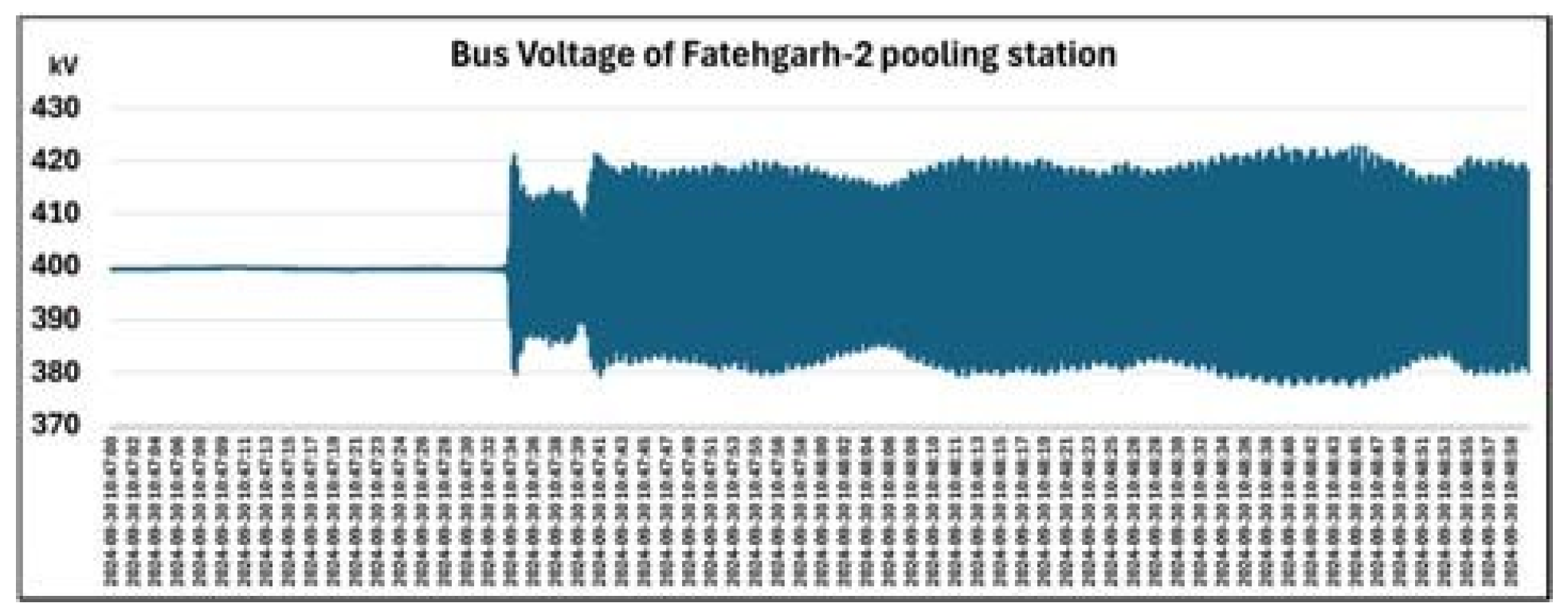
Figure 2.
Variation of reactive power from plant w.r.t POI voltage during oscillation observed on 30th September 2024.
Figure 2.
Variation of reactive power from plant w.r.t POI voltage during oscillation observed on 30th September 2024.
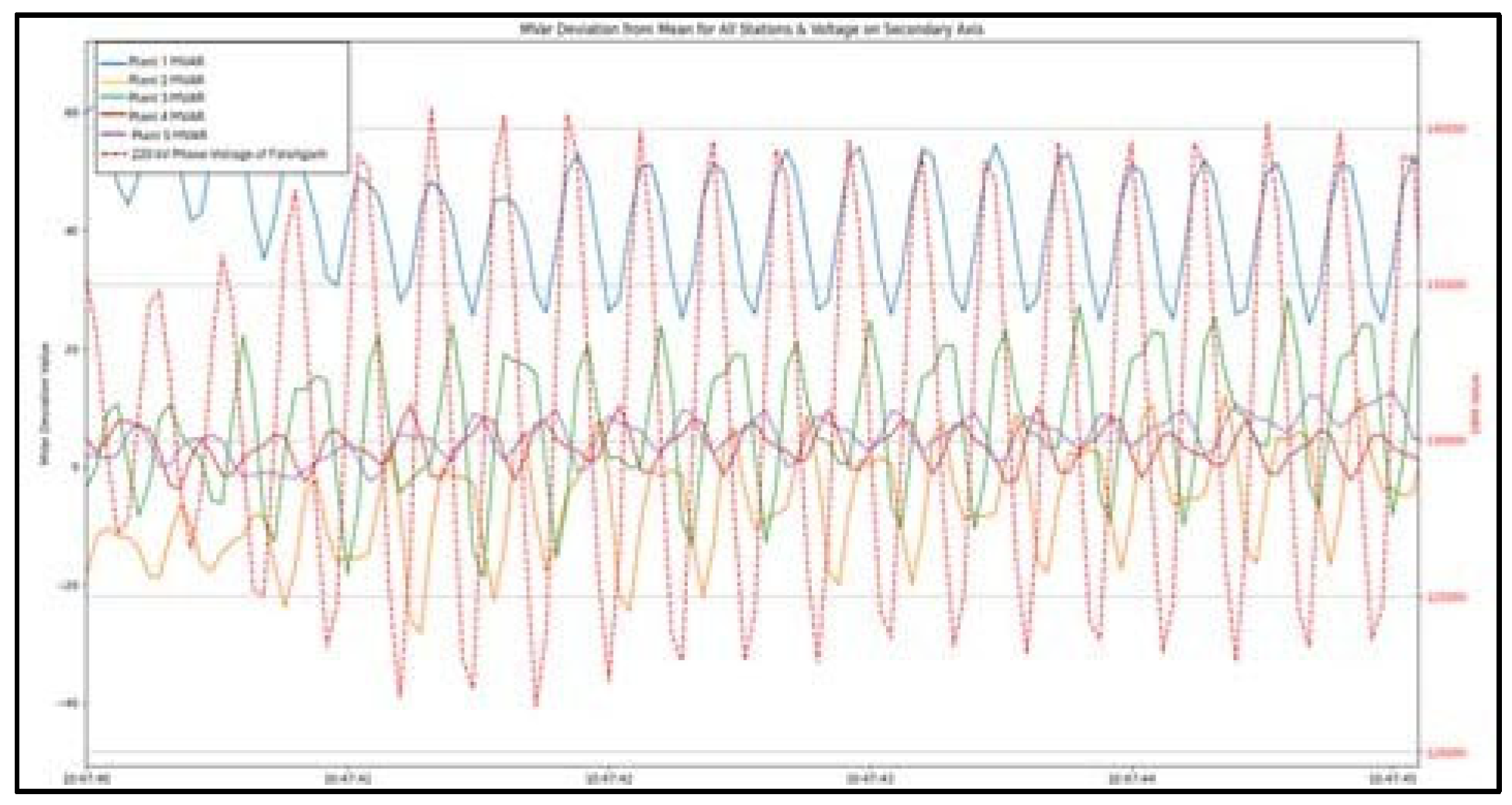
Figure 3.
Schematic of Power Plant Controller.
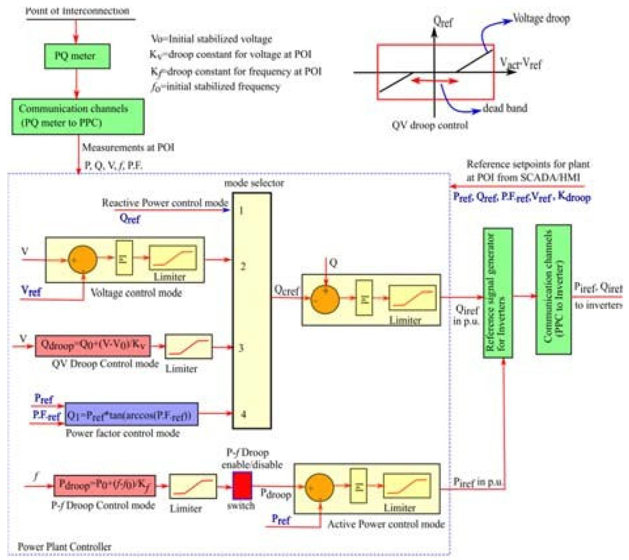
Figure 4.
Signal delays associated with PPC.
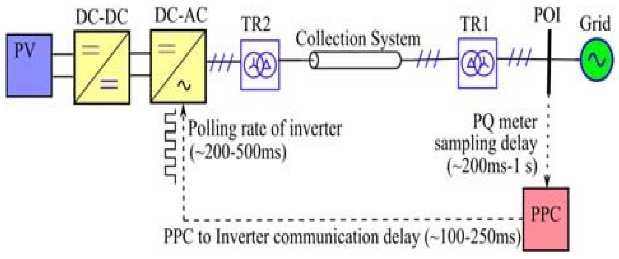
Figure 5.
Illustration of out-of-phase injection of reactive power due to PPC delay (a) Oscillatory component of Line-Line rms voltage at POI (0.1 p.u) (b) Required reactive power(Only varying component) variation to damp voltage oscillations (c) Actual reactive power(Only varying component) injected due to PPC delay.
Figure 5.
Illustration of out-of-phase injection of reactive power due to PPC delay (a) Oscillatory component of Line-Line rms voltage at POI (0.1 p.u) (b) Required reactive power(Only varying component) variation to damp voltage oscillations (c) Actual reactive power(Only varying component) injected due to PPC delay.
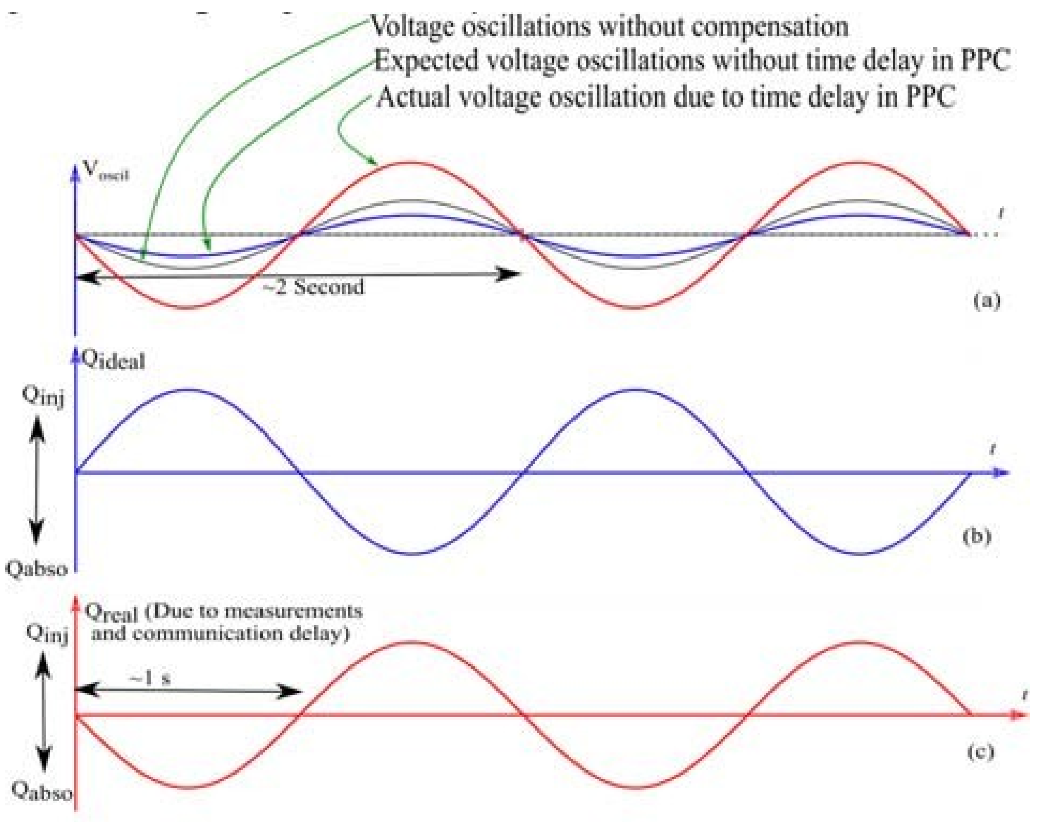
Figure 6.
HIL simulation of PPC experimental setup.
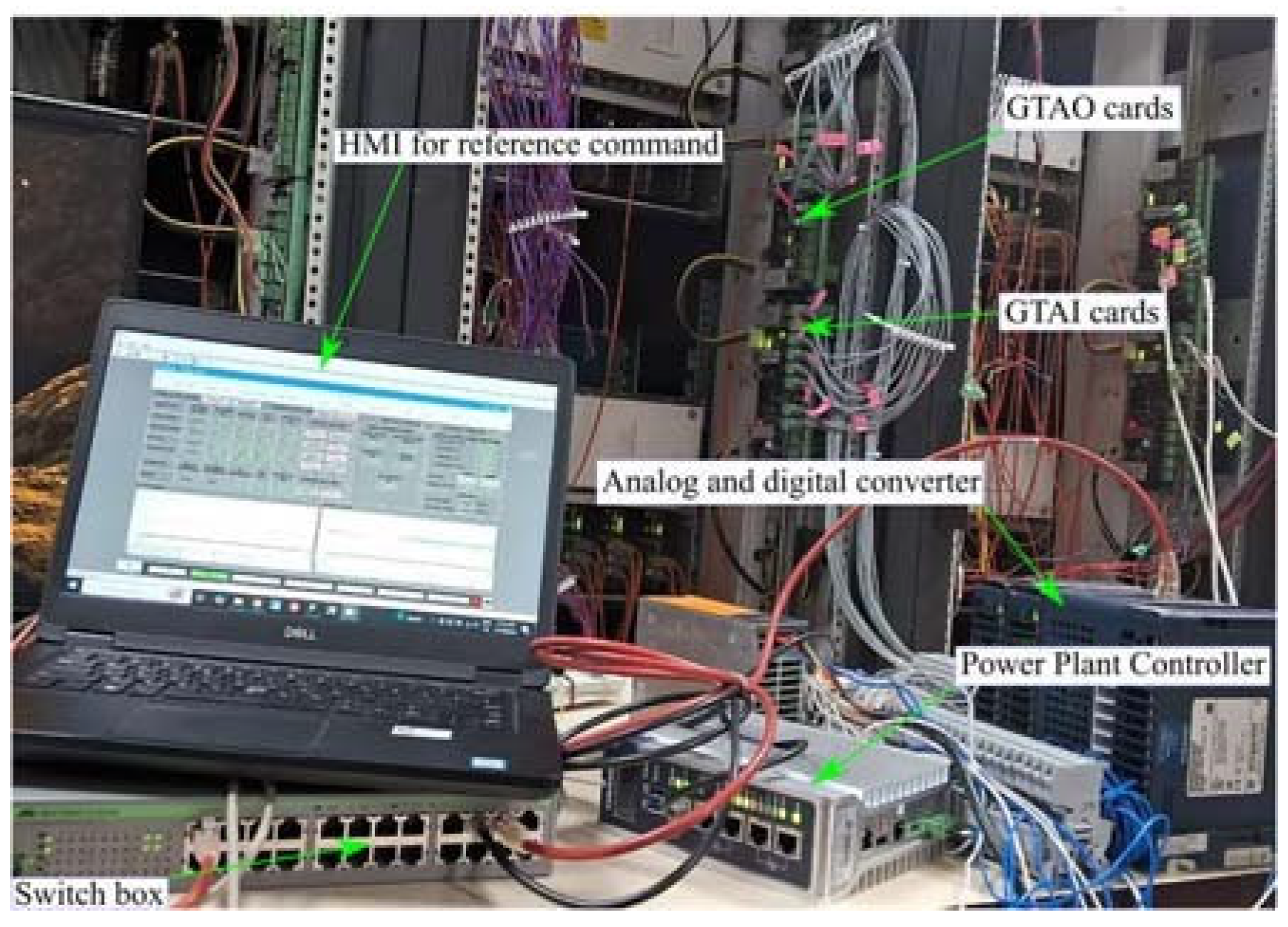
Figure 7.
Schematic for HIL simulation of PPC testing setup.
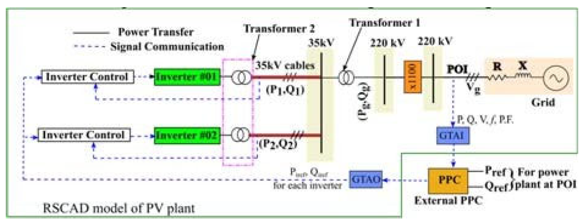
Figure 8.
Performance of RE plant in fixed Q control with Qref=0. Qm at POI (Qmeasured at POI), Qm at PPC (Sampled reactive power received at PPC from PQ meter). Qref from PPC (Reactive power command from PPC), Qiref at inverter (Reactive power command received from PPC at inverter), Vpoi (Voltage at POI), Vg (Grid voltage without reactive power compensation from PPC), RT (Ride through mode), Viac-Inverter terminal voltage (p.u).
Figure 8.
Performance of RE plant in fixed Q control with Qref=0. Qm at POI (Qmeasured at POI), Qm at PPC (Sampled reactive power received at PPC from PQ meter). Qref from PPC (Reactive power command from PPC), Qiref at inverter (Reactive power command received from PPC at inverter), Vpoi (Voltage at POI), Vg (Grid voltage without reactive power compensation from PPC), RT (Ride through mode), Viac-Inverter terminal voltage (p.u).
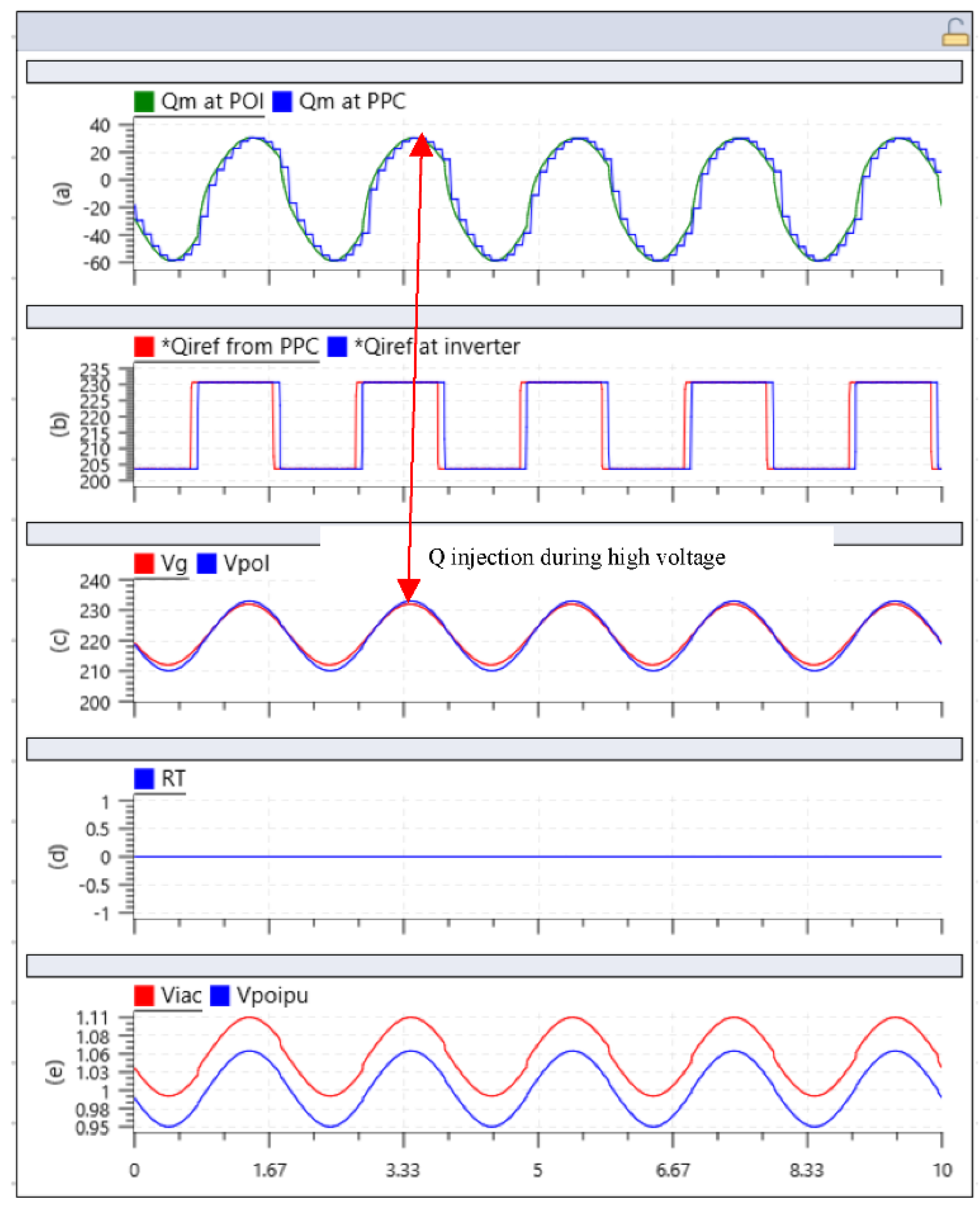
Figure 9.
Performance of RE plant in p.f mode with p.f 0.99 leading. Qref=0. Qm at POI (Qmeasured at POI), Qm at PPC (Sampled reactive power received at PPC from PQ meter). Qref from PPC (Reactive power command from PPC), Qiref at inverter (Reactive power command received from PPC at inverter), Vpoi (Voltage at POI), Vg (Grid voltage without reactive power compensation from PPC), RT (Ride through mode), Viac-Inverter terminal voltage (p.u).
Figure 9.
Performance of RE plant in p.f mode with p.f 0.99 leading. Qref=0. Qm at POI (Qmeasured at POI), Qm at PPC (Sampled reactive power received at PPC from PQ meter). Qref from PPC (Reactive power command from PPC), Qiref at inverter (Reactive power command received from PPC at inverter), Vpoi (Voltage at POI), Vg (Grid voltage without reactive power compensation from PPC), RT (Ride through mode), Viac-Inverter terminal voltage (p.u).
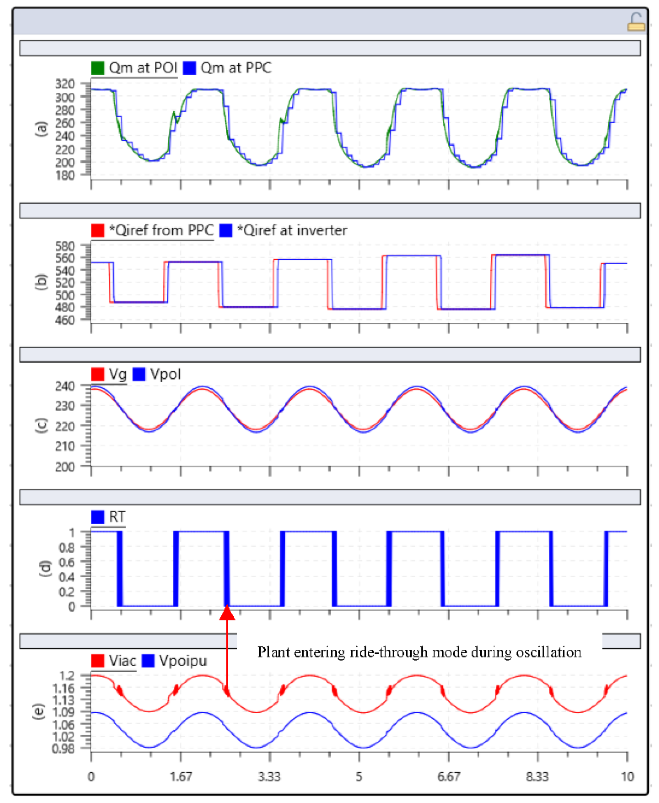
Figure 10.
Performance of plant in voltage droop control mode (dead band=1%, droop=3%). Qref=0. Qm at POI (Qmeasured at POI), Qm at PPC (Sampled reactive power received at PPC from PQ meter). Qref from PPC (Reactive power command from PPC), Qiref at inverter (Reactive power command received from PPC at inverter), Vpoi (Voltage at POI), Vg (Grid voltage without reactive power compensation from PPC), RT (Ride through mode), Viac-Inverter terminal voltage (p.u).
Figure 10.
Performance of plant in voltage droop control mode (dead band=1%, droop=3%). Qref=0. Qm at POI (Qmeasured at POI), Qm at PPC (Sampled reactive power received at PPC from PQ meter). Qref from PPC (Reactive power command from PPC), Qiref at inverter (Reactive power command received from PPC at inverter), Vpoi (Voltage at POI), Vg (Grid voltage without reactive power compensation from PPC), RT (Ride through mode), Viac-Inverter terminal voltage (p.u).
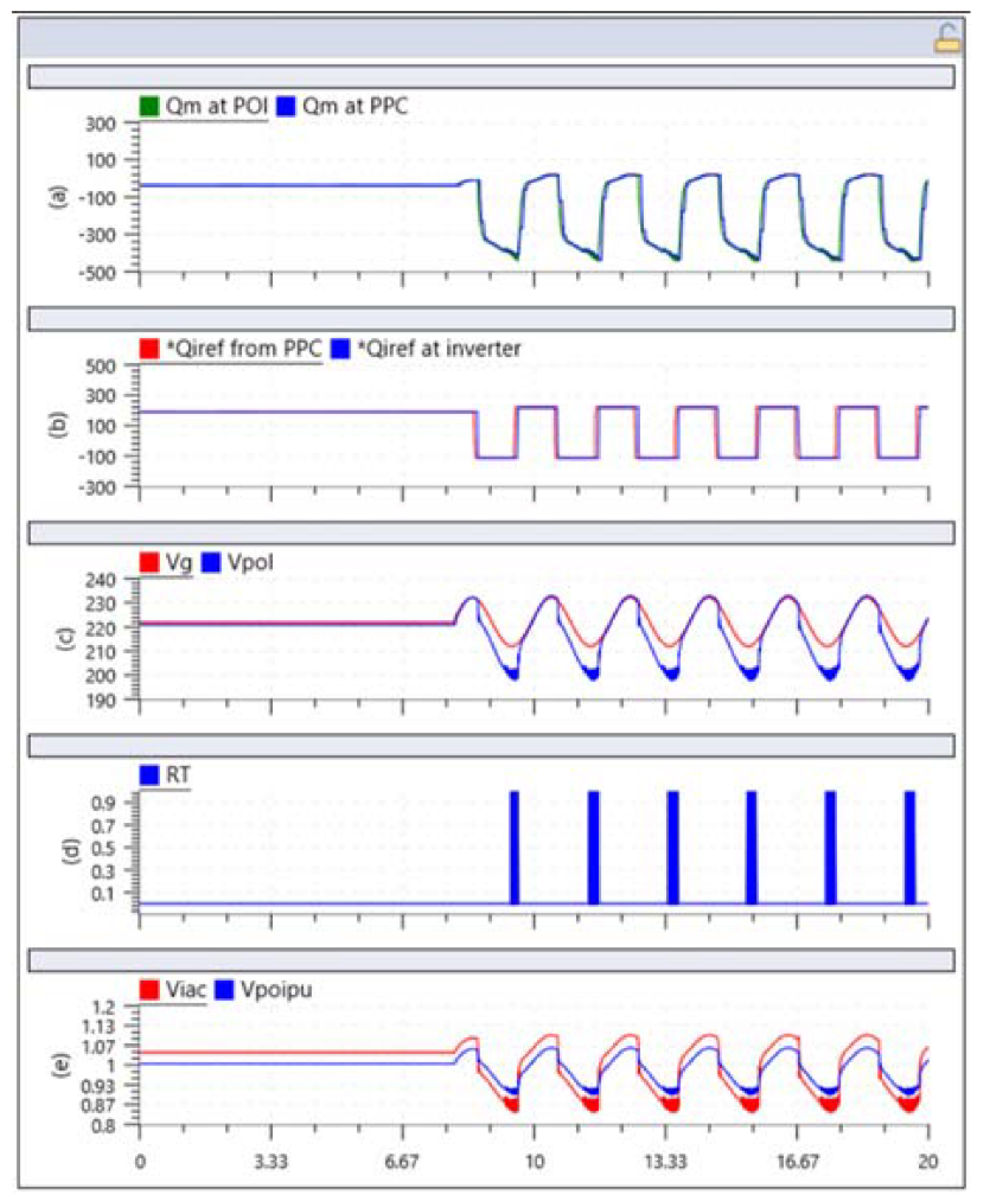
Figure 11.
Performance of plant in voltage droop control mode(dead band=2%,droop=10%). Qref=0. Qm at POI (Qmeasured at POI), Qm at PPC (Sampled reactive power received at PPC from PQ meter). Qref from PPC (Reactive power command from PPC), Qiref at inverter (Reactive power command received from PPC at inverter), Vpoi (Voltage at POI), Vg (Grid voltage without reactive power compensation from PPC), RT (Ride through mode), Viac-Inverter terminal voltage (p.u).
Figure 11.
Performance of plant in voltage droop control mode(dead band=2%,droop=10%). Qref=0. Qm at POI (Qmeasured at POI), Qm at PPC (Sampled reactive power received at PPC from PQ meter). Qref from PPC (Reactive power command from PPC), Qiref at inverter (Reactive power command received from PPC at inverter), Vpoi (Voltage at POI), Vg (Grid voltage without reactive power compensation from PPC), RT (Ride through mode), Viac-Inverter terminal voltage (p.u).
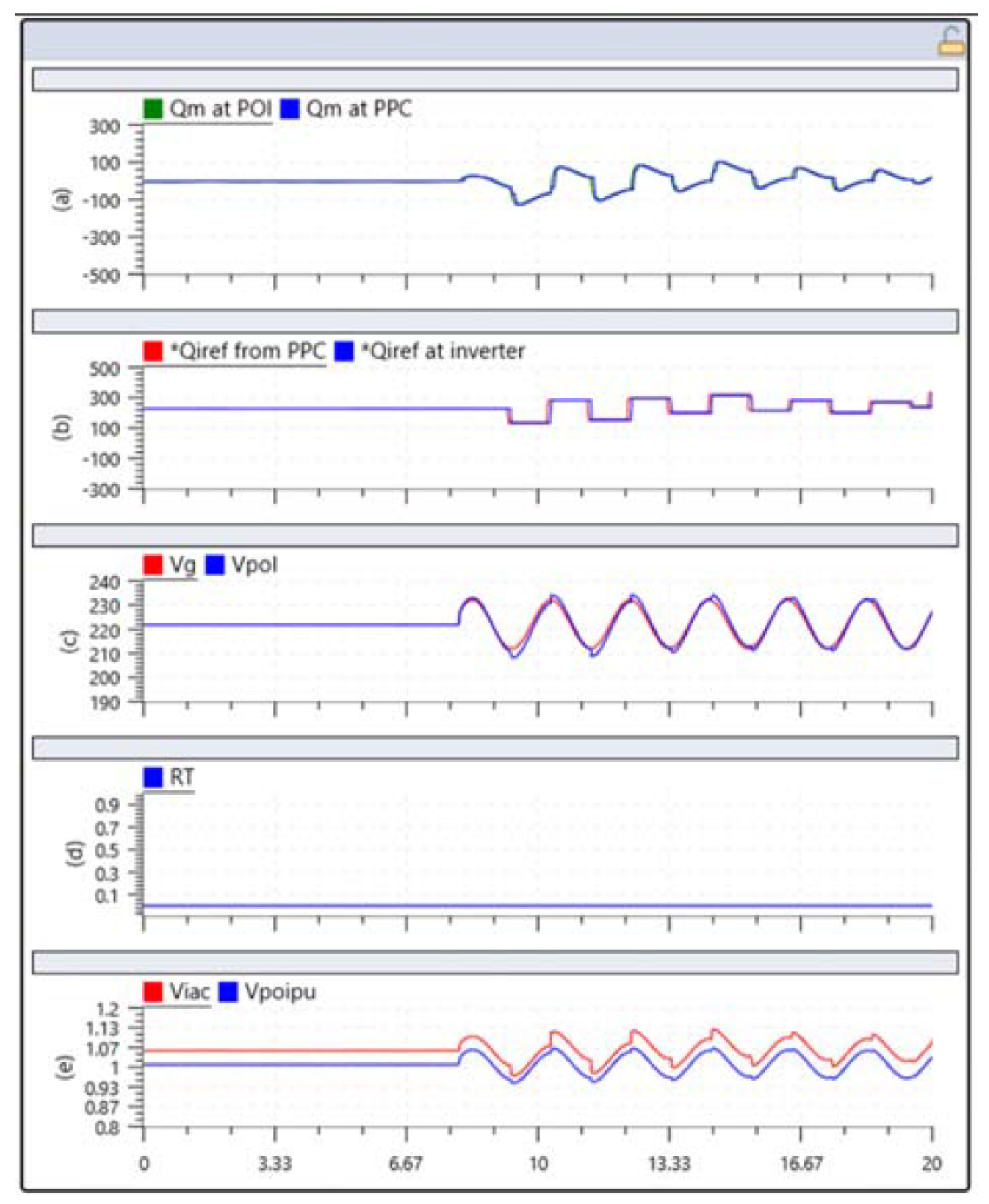

Table 1.
System parameters for PV plant model.
| System Parameters | |
|---|---|
| AC grid | 220kV |
| PQ Meter Sampling period | 100ms |
| PQ Meter to PPC delay | 500ms |
| PPC to Inverter time delay | 500ms |
| Inverter Polling rate | 500ms |
| Plant Capacity | 1800 MW |
| Short-circuit ratio at POI | 4 |
| HVRT (Inverter end) | 1.15 |
| LVRT(Inverter end) | 0.85 |
| HVRT (PPC end) | 1.1 |
| LVRT(PPC end) | 0.9 |
Disclaimer/Publisher’s Note: The statements, opinions and data contained in all publications are solely those of the individual author(s) and contributor(s) and not of MDPI and/or the editor(s). MDPI and/or the editor(s) disclaim responsibility for any injury to people or property resulting from any ideas, methods, instructions or products referred to in the content. |
© 2025 by the authors. Licensee MDPI, Basel, Switzerland. This article is an open access article distributed under the terms and conditions of the Creative Commons Attribution (CC BY) license (http://creativecommons.org/licenses/by/4.0/).
Copyright: This open access article is published under a Creative Commons CC BY 4.0 license, which permit the free download, distribution, and reuse, provided that the author and preprint are cited in any reuse.


