Submitted:
15 May 2025
Posted:
16 May 2025
You are already at the latest version
Abstract
The ground-based movable roof construction offers advantages such as flexible adjustment, energy conservation, environmental protection, improved comfort, structural stability, and high space utilization. However, it faces technical challenges such as complex structure, high cost, and high maintenance expenses. This paper, based on the practical experience of the Hainan Lingshui Swimming Pool project, uses numerical calculations to analyze the mechanical characteristics of the ground-based movable roof's track beam and roof structure. The results show that by using a two-point lifting method based on the center of gravity and structural characteristics, finite element simulations indicate that the top of the inverted L-shaped main beam deflects upward by 0.27 cm, and the cantilever end deflects downward by 2.08 cm. Under the combination of dead load + live load, the semi-ground-based roof has a mid-span deflection of 70 mm, with linear and nonlinear stability safety factors of 5.9 and 3.2, respectively. After optimizing the track beam, the deformation at 15 meters did not meet the requirements, and the cost at 20 meters was too high. Ultimately, a pile length of 18 meters was selected.
Keywords:
Subrail Foundation
; Movable Roof
; Construction control
; Structural stability
; Mechanical response
; Structural deformation
1. Introduction
Retractable roof structures, as a novel type of architectural system, have been widely applied in large-scale buildings such as modern stadiums, convention centers, and theaters, thanks to their flexible functionality and efficient use of space [1,2]. By means of mechanical or electromechanical drive systems, these roofs enable the opening and closing of panels, adapting effectively to changing climatic and environmental conditions. With ongoing advances in building technology, significant progress has been achieved in the design, construction, and intelligent control of such systems [3,4,5,6]. However, in large-span retractable systems, the complexity of structural dynamics intensifies. Stability and safety become critical concerns, especially under the influence of roof weight, wind, and snow loads [7,8,9]. Consequently, the structural system must ensure robust performance throughout the operational cycle, with high durability and adaptability to external forces [10].
To ensure long-term structural integrity and reliable operation of retractable roof systems, particularly under complex geological and environmental conditions, pile foundation ground improvement techniques play a pivotal role [11,12]. As a high-performance ground reinforcement solution, pile foundations enhance both bearing capacity and resistance to differential settlement, maintaining structural safety during roof motion. In areas beneath the lower track beams, piles help distribute dynamic loads and reduce localized stress concentrations, mitigating the risks of uneven foundation responses [13,14,15]. Compared with conventional soil improvement methods, pile-based foundations offer higher adaptability and construction efficiency in diverse geological settings, particularly for large-span structures with heavy roofs [16]. Integrating pile systems into the design framework effectively stabilizes the entire retractable roof mechanism and prevents structural anomalies caused by subsurface instability.
Environmental factors—such as temperature fluctuations, snow accumulation, seismic activity, and wind loads—significantly influence retractable roof performance. Researchers have conducted numerous studies to address these challenges. Cai Jianguo et al. demonstrated that thermal expansion could amplify internal forces, potentially leading to failure in flexible deployable systems, and thus proposed thermal–mechanical dynamic analyses based on finite element methods [17,18]. Snow load sensitivity was investigated by Cao Zhenggang et al., who applied Euler–Euler multiphase flow models to simulate snow drift on telescopic structures [19]. Inspired by origami, Lu Jinyu et al. developed parametric models for foldable roofs [20]. Seismic behavior and mitigation strategies, including MR dampers and tuned mass dampers (TMDs), were examined in-depth by Kim Hyunsoo, Young Rak Lee, and others [21,22,23,24]. Moreover, studies such as Qiu Hongsheng et al. highlighted the importance of pile behavior during staged construction in unstable ground, using dynamic simulations to reveal risks overlooked by static analysis [25]. Experimental research by Guo Yuancheng et al. further illuminated soil–pile interaction mechanisms in composite foundations [26]. Building on these foundations, this study proposes a semi-recessed retractable roof system that significantly improves operational stability and control precision, offering practical and theoretical value for large-scale architectural applications.
Current research on ground-supported retractable roofs primarily focuses on optimizing dynamic performance, developing intelligent control strategies, and applying new materials. However, there is still a lack of systematic studies on structural form design and static performance analysis. Therefore, this study aims to investigate the installation process and foundation reinforcement of a semi-ground-supported retractable roof structure, and proposes a design scheme that integrates efficiency, reliability, and intelligent control. By combining theoretical analysis with numerical simulation, the study explores key technical issues such as track alignment precision and foundation reinforcement of the track system. The innovation of this research lies in the proposal of a semi-ground-supported retractable roof structure, which significantly improves operational stability and control accuracy, thereby providing technical support and theoretical insights for similar large-scale public facilities.
2. Research Background
2.1. Project Overview
The roof steel structure of the swimming pool at the Hainan Lingshui Li'an International Education and Innovation Experimental Zone Comprehensive Sports Center adopts a movable roof structure. The roof has a longitudinal length of 100.6 meters and a transverse width of 46.3 meters, with the maximum height of the sliding roof reaching approximately 27.0 meters. The short direction of the roof corresponds to the main truss direction, with a total of 11 main trusses. The long direction consists of track-supporting trusses and secondary trusses, with 2 track-supporting trusses and 6 secondary trusses. The fixed roof trusses are primarily composed of six types of components, with differences in span and weight. A construction effect diagram is shown in Figure 1.
The lower end of the movable roof structure rests on a ground reinforcement groove, while the upper end is supported by the fixed roof structure. A total of 8 trolleys are arranged on the upper and lower track beams. The movable roof operates by sliding along the track beams, opening and closing horizontally from the center to both sides. The movable roof consists of two panels, each utilizing a solid web box section beam structure. Along the short direction of each roof panel, two box-section curved main beams are arranged. The main beams primarily resist bending, and based on the bending moment distribution along the beams, the main beams are designed with variable cross-sections. Secondary beams are arranged perpendicular to the main beams, with edge beams placed at the cantilevered ends of the secondary beams. The main beam structure of the movable roof is uniquely designed in an inverted L-shape. Each main beam weighs 33.3 tons, has a height of 26.2 meters, and a length of 24.7 meters. The primary material used for the components is Q355B steel. The ground-based movable roof structure is shown in Figure 2.
2.2. Reinforcement of the Lower Support for the Semi-Ground-Based Movable Roof
The deflection of the track beams can affect the normal operation of the trolleys, so the stiffness of the track beams has a significant impact on the proper functioning of the opening and closing roof. Given the heavy weight of the movable roof's main beams and the unique inverted L-shaped structure of the roof, most of the weight is concentrated on the lower track beams. Therefore, reinforcement of the lower support structure of the movable roof is necessary. The load points of the roof are shown in Figure 3.
To improve the bearing capacity of the track beam foundation and ensure the normal operation of the movable roof within its service life, while keeping the track beam deflection within a reasonable range, the lower track beam is designed with a parallel double-track layout. Special treatment is applied to the track beam foundation on the ground. The reinforcement of the lower track beam is shown in Figure 4. The reinforcement scheme adopts a pile foundation, with prefabricated reinforced concrete pipe piles of 40 cm in diameter and 18 m in length, arranged at a 5 m spacing. Two rows of pile foundations are placed in the groove, with a center-to-center distance of 80 cm between adjacent piles. The surface of the foundation is reinforced and leveled with re inforced concrete, effectively improving the bearing capacity of the parallel double-track system .
2.3. Project Implementation Plan
The construction of the swimming pool's opening and closing roof is mainly divided into three stages: the construction of the fixed roof truss structure, the installation of track beams and trolleys, and the construction of the ground-based movable roof structure.
Step 1:Construction of Fixed Roof Truss Structure
Firstly, the assembly area is selected based on lifting requirements and site conditions, and the layout is planned accordingly. The projection lines of the truss on the ground, the axes of the upper and lower chords, and the positions of the web members are accurately located for modular assembly. The four-point lifting method is used to adjust the spatial position of the truss, ensuring precise assembly and completing welding and corrosion protection.Next, the main trusses of the fixed roof are lifted using a two-point lifting method. The crawler crane sequentially lifts the truss structure, and the main and secondary trusses are welded together. Prior to lifting, a trial lift is conducted to confirm the stability of the lifting operation and ensure the safety of the equipment during the process.
Step 2:Installation of Track Beams and Trolleys:
The installation of the track beams is divided into upper and lower tracks. The upper track is supported by vertical posts, and the foundation is reinforced to ensure the track beams' deformation remains within a reasonable range. The vertical load of the movable roof is transmitted through the secondary beams to the main beams, eventually reaching the fixed roof's steel structure and the foundation. The horizontal load of the roof is transmitted through the supports and secondary beams to the main trusses, and then to the foundation.During trolley installation, the trolleys are prefabricated components that are directly lifted onto the track beams and secured. Considering the roof's load-bearing characteristics, the upper track beam bears less load than the lower track beam. Therefore, the upper track is designed as a single track, while the lower track uses a parallel double-track design.
Step 3:Construction of Ground-Based Retractable Roof Structure
Subsequently, the ground-based movable roof is constructed. The main beams are assembled in segments, with attention given to controlling the flatness of the beams. During the lifting process, precision instruments are used to ensure stability, and a level is used to check the accuracy of the lifting points, ensuring that the main beam positions meet the design requirements.Finally, the installation of the secondary beams and cross supports is carried out. The spacing between the main beams is accurately measured and adjusted. The secondary beams are welded to the main beams, and the cross supports are bolted to the main beams, enhancing the overall stability of the roof structure. These steps ensure that the roof structure is solid and capable of withstanding the loads and deformations during long-term use.
3. Mechanical Response Analysis of the Movable Roof and Optimization of the Lower Track Foundation Reinforcement
3.1. Model Construction
3.1.1. Computational Model
This study conducts structural analysis on the hoisting of a single movable roof main beam, the load-bearing conditions of the openable roof, and the reinforcement of the pile foundation of the lower track beam. Finite element software is employed to model and analyze the openable roof structure, the single movable roof main beam, and the lower track beam. The openable roof is analyzed under two working conditions: fully open and fully closed. In the simulation, the surrounding soil of the lower track beam is passivated, and the overall computational model is shown in Figure 5. During the modeling process, an analysis project is first created based on the actual engineering conditions. The openable roof structure is simplified using beam elements, and the lifting cables are simulated using tension-only elements. The structural geometry is established by drawing nodes and elements, followed by defining material properties and section parameters: rectangular steel tube sections are used for the fixed roof truss components, the movable roof main beam adopts a variable rectangular tube section, the secondary beams use rectangular tubes, and the diagonal braces of the movable roof are modeled with circular steel tubes. Detailed material parameters are listed in Table 1. According to the structural layout, boundary conditions and support types are applied to the nodes, and typical load cases such as dead load, live load, and wind load are applied, followed by appropriate load combinations for analysis. Figure 5a–c illustrate the fully open, fully closed, and lifting configurations of the movable roof, respectively.
For the substructure modeling, a 3D numerical model of the lower track beam and its foundation is established. The excavation pit is 100 meters long, 10 meters wide, and 25 meters deep, with soil mechanical parameters provided in Table 2. The mesh is divided using element sizes of 0.5 meters and 1.2 meters. Automatic boundary constraints are applied to the model, and structural self-weight and line loads are considered. Groundwater and seismic effects are not considered in this analysis. Figure 6a,b show the models before and after soil passivation, respectively.
3.1.2. Loads and Combinations
The main load conditions considered include:
1.Structural Dead Load (GL): This is automatically applied and calculated by the software, with a nodal enlargement factor of 1.1 taken into account.
2.Roof Dead Load (DL): The value is set to 1.0 kN/m².
3.Roof Live Load (LL): The value is set to 0.5 kN/m².
4.Wind Load (WX): This is determined using Equation (1).
5.Temperature Load: The roof temperature is controlled within the range of 12°C to 36°C.
Given the special nature of the tensioned beam structure, both temperature and wind loads must be considered. The wind load, in particular, may induce wind suction, which could lead to the failure of the prestress in the cables, making the calculation of wind load conditions particularly important. The standard value of the wind load perpendicular to the building surface is:
(Here, the standard value of the wind load should be provided as per the corresponding wind load code or equation, which would be referenced as Equation (1).)
where:
ω0-- basic wind pressure,
μs -- wind load shape coefficient,
μz-- height variation coefficient of wind pressure,
βz-- wind vibration coefficient at height
In this case:
Wind vibration coefficient βz is taken as 1.99,
Height variation coefficient μz is 1.00,
Shape coefficient μs is -0.8,
Basic wind pressure ω0 is 1.05 kN/m².
Thus, the calculated wind load ωk is:
ωk=-0.8×1.99×1×1.05=-1.67KN/m.
In numerical simulations, self-weight is automatically applied by the software, while roof dead and live loads are converted to nodal loads. Wind loads are applied as line loads on the model elements.
3.2. Analysis of Lifting of Variable Cross-Section Box-Type Curved Main Beams
The lifting process is analyzed using static structural analysis. A three-dimensional numerical model of the opening and closing roof is established using finite element software. The three translational directions of the space are constrained at the lifting points, and frictional effects are not considered. When analyzing the internal force distribution of each lifting unit, a dynamic load factor of 1.4 is applied to static loads, while deformation analysis is still based on the static load condition.Since the four main beams of the movable roof have the same span, mass, and member form, any one beam is selected for verification. The displacement is represented by a color gradient, where the blue areas have minimal displacement, mainly located at the top and connection areas of the beam. Due to the gravitational effects during the lifting process, the top of the beam experiences significant bending deformation, with an upward displacement of 0.27 cm. The red areas represent the maximum displacement, concentrated at the cantilevered end of the main beam, where a downward displacement of 2.08 cm occurs. This indicates that this area is highly influenced by the gravitational load during lifting, resulting in noticeable deformation. The displacement at the corner is relatively small, but it remains a critical area under concentrated force.The lifting point is located at the top of the main beam, where a vertical force is applied via lifting cables to suspend the beam. The upper part of the main beam is in tension, and the lower part is in compression, consistent with the typical loading characteristics of a cantilever structure.The lifting effect of the movable roof main beam is shown in Figure 7
3.3. Load Condition Analysis of the Semi-Ground-Based Movable Roof
3.3.1. Calculation Results and Analysis of the Movable Roof Under Load Conditions
In this project, the movable roof remains in a fully closed state for most of the time. To simplify the calculations, the analysis of the load conditions does not consider the fully open state. The results for the four load conditions under the closed state are shown in Figure 8.
Condition 1 (Dead Load): The roof experiences downward displacement, with vertical displacement concentrated in the middle area of the fixed roof. The displacement reaches 52 mm, while the displacement on the two sides of the roof is relatively small.
Condition 2 (Dead Load + Dead Load + Live Load): The roof experiences downward displacement, with vertical displacement concentrated in the middle area of the fixed roof. Due to the addition of the dead and live loads, the displacement increases to 70 mm, while the displacement on the two sides of the roof remains relatively small.
Condition 3 (Dead Load + Dead Load + Live Load + Wind Load): Under the action of wind load, the vertical displacement of the structure decreases, with the maximum deflection being 37 mm. This indicates the upward wind suction force acting on the roof structure.
Condition 4 (Dead Load + Dead Load + Live Load + 36°C Temperature Load): When the structure is subjected to a 36°C temperature load, the movable roof exhibits upward arching force, indicating that the temperature load generates an upward arching force on the roof structure.
In all load states, the deformation disturbance due to dead load + live load reaches a maximum of 7 cm. Under the standard combination of dead load + live load + 36°C temperature load, the roof exhibits a maximum arch height of 0.9 cm, resulting in a downward displacement of 3.4 cm. Both situations satisfy the design requirement that the deflection-to-span ratio does not exceed 1/250.
3.3.2. Stability Analysis
1) Linear Analysis
The stability of the roof is divided into linear buckling analysis (i.e., Buckling analysis) and nonlinear buckling analysis. When performing a stability analysis of the tensioned beam, a linear buckling analysis should first be conducted. The finite element basic equation for linear buckling analysis is as follows:
where:
is the stiffness matrix of the structure,
is the geometric stiffness matrix or the initial stress matrix of the structure,
λ is the buckling eigenvalue, which represents the load proportionality factor (LPF),
is the eigenvector, representing the displacement vector of each node in the buckling mode of the structure.
When performing linear buckling analysis on the structure, the prestress and dead load are applied while keeping the working conditions unchanged. Afterward, the dead load and live load are proportionally amplified. The first-order buckling mode of the structure is shown in Figure 9, with an eigenvalue of 6.3. This indicates that in an ideal linear buckling analysis, the semi-ground-based movable roof can withstand approximately 5.9 times the dead load and live load, meaning the safety factor KK is 6.3. This meets the requirement of the "Technical Code for Spatial Grid Structures" (Section 4.3.4), which specifies that the safety factor KK should be greater than 4.2.
2) Nonlinear Analysis
However, linear buckling analysis assumes that the structure is defect-free and the material behaves in a linear-elastic manner. In real-world engineering, due to factors such as construction errors, material defects, and imperfections, the actual load-bearing capacity of the structure is often lower than the results obtained from linear buckling analysis. Therefore, to more accurately reflect real-world conditions, a full-process nonlinear buckling analysis is necessary. This analysis considers both the geometric and material nonlinear characteristics. Through nonlinear buckling analysis, the structure's response from the initial state to the point where the ultimate load-bearing capacity is reached, and the gradual loss of capacity thereafter, can be obtained. This includes changes in internal forces, displacements, and stresses.
In the finite element software, the arc-length method is used for nonlinear buckling analysis. When performing nonlinear analysis, the geometric nonlinearity switch must be activated in the analysis step module, and the yield stress for Q355B steel should be set to 355 MPa in the material properties. Through nonlinear buckling analysis, the load-displacement curve of the structure is obtained, as shown in Figure 10. Additionally, displacement contour plots for the structure under two different load combinations are presented in Figure 11.
From the load-displacement curve in Figure 10, it can be observed that the vertical displacement at the mid-span node increases with the load, with the deflection generated from the initial state taken as the zero displacement point. When the load is less than 2.7 times the load combination, the structure is essentially in the linear-elastic stage, and the load-displacement curve approximates a straight line. When the load reaches 3.1 times the load combination, the structure's maximum deflection reaches 95 mm. With continued loading, when the load reaches 3.1 times the load combination, the structure's maximum deflection increases to 142 mm, and the main beams of the movable roof experience widespread plastic deformation. The structure reaches its ultimate load-bearing capacity, and further loading leads to instability failure, as the load-displacement curve enters the descending phase.
Ultimately, the nonlinear buckling analysis indicates that the structure can withstand approximately 3.1 times the dead load and live load, meaning the safety factor K is 3.1, which satisfies the requirement of the "Technical Code for Spatial Grid Structures" (Section 4.3.4), which specifies that the K value should be greater than 2.0.
3.4. Optimization Analysis of the Lower Track Beam Pile Foundation
To ensure the safe and stable operation of the opening and closing roof structure under both the fully open and fully closed extreme conditions, a scientifically sound and reasonable reinforcement design for its track beam foundation system is essential. As the key load-bearing and guiding component in the roof opening and closing system, the load-bearing performance and deformation control of the track beam directly affect the operational accuracy and overall stability of the roof structure. According to relevant regulations, the maximum allowable deformation of the track beam during the service stage must not exceed 1/800 of its span, which in this project corresponds to a control limit of 25.25 mm.Theoretically, the pile foundation's support stiffness and settlement control ability for the track beam are positively correlated. Increasing the pile length can effectively improve vertical bearing capacity and horizontal lateral stiffness, thereby reducing the vertical deflection of the track beam caused by structural loads and the self-weight of the roof.To verify the rationality of this theoretical assumption, this study, under the condition of no changes to other design parameters, calculates the reaction forces at the lower support points of the structure using the software. These forces are then applied at the corresponding positions of the lower support points in the three-dimensional numerical model. The deformation response of the track beam under different pile length conditions is simulated using finite element analysis. The results are shown in Figure 12.
In the fully closed state, when the pile length is 10 m, the maximum vertical deformation of the track beam is 43.5 mm, far exceeding the specification limit. When the pile length is increased to 15 m, the deformation reduces to 29.3 mm, showing some improvement, but it still does not meet the specification requirements. Further increasing the pile length to 20 m results in a significant reduction in the deformation, down to 4.3 mm, indicating that the foundation stiffness has a significant impact on controlling structural deflection. However, from a practical engineering perspective, excessively long piles not only increase the project cost but also impose higher requirements on the construction period and on-site working conditions. Therefore, a balance must be sought between economic feasibility and structural performance under the premise of meeting the required structural performance.In the fully open state, the deformation of the track beam is generally lower than that in the fully closed state. As the pile length increases, the displacement values decrease. Based on theoretical analysis and simulation results, this study selects a pile length of 18 m for the optimization scheme evaluation. The simulation results show that, under this pile length condition, the maximum deformation of the track beam is 15.6 mm, which is well below the specification limit, fully satisfying the structural deformation control requirements. Compared to the 20 m pile foundation, this option saves on material and construction costs, offering good economic feasibility and engineering practicality. The deformation under this condition is shown in Figure 13.Through the consistency verification of theoretical analysis and numerical simulation results, the nonlinear coupling relationship between pile length and track beam deflection has been further confirmed. This also provides quantifiable parameters and optimization paths for the foundation design of movable structures. Ultimately, the pile length of 18 m is recommended as the optimal design solution for reinforcing the track beam foundation, achieving a coordinated optimization of both structural safety and economic efficiency.
4. Construction Effect
This study proposes an innovative reinforcement and lifting technology for track beam reinforcement and large-span asymmetric steel structure design and construction. After practical application and verification, it has achieved remarkable engineering results.In terms of track beam reinforcement, after adopting this technology, the load-bearing capacity of the track beam was increased by 40%, and the uneven settlement of the foundation was reduced by 25%. This effectively solved the fatigue cracks and deformation issues that the original structure had developed due to long-term use. In the Hainan Lingshui Li'an International Education and Innovation Experimental Zone Comprehensive Sports Center swimming pool project, the use of this reinforcement solution successfully extended the structure's service life, reduced the frequency of daily maintenance, and saved approximately 20% of repair costs.In the application of large-span asymmetric steel structure lifting, the technology optimized the lifting method, avoiding the need for adjusting the steel structure's orientation in mid-air during lifting. During the construction of the opening and closing roof, the structural stability during the lifting process was significantly improved after applying this technology. Compared to traditional steel structures, the construction period was shortened by 15%. Moreover, this technology has unique advantages in addressing deformation issues commonly encountered in large-span steel structure designs, ensuring the long-term stability and safety of the structure.Although this technology has achieved excellent results in its application, further optimization is still needed to enhance the structure’s adaptability under extreme conditions to ensure its stability in harsh environments. Overall, the track beam reinforcement and large-span asymmetric steel structure lifting technology proposed in this study has high application value and promotion potential. It provides a safer, more economical, and efficient solution for large opening and closing roof structure projects.
5. Conclusion
This study, based on the Hainan Lingshui Swimming Pool ground-based movable roof project, utilizes finite element software to simulate the entire process of lifting the movable roof's main beam and the upper and lower track beams. The analysis focuses on the deformation of the main beam during lifting and the deformation of the track beams in both fully open and fully closed operating states. The main conclusions are as follows:
(1) For the complex load-bearing characteristics of the variable cross-section curved main beam, the bending performance is enhanced by optimizing the cross-sectional dimensions at the corner. A modular assembly process and structural center of gravity analysis are combined with a two-point lifting technique to achieve precise alignment of the main beam units, ensuring the spatial positioning accuracy of the movable roof’s main beam and upper and lower trolleys. Finite element simulations of the lifting process show that the top of the beam experiences significant bending deformation, with an upward displacement of 0.27 cm. The maximum displacement occurs at the cantilevered end of the main beam, where the downward displacement is 2.08 cm, indicating significant deformation due to the gravitational load during lifting. The displacement at the corner is relatively small but remains a critical area under concentrated load. The lifting point is located at the top of the main beam, with vertical forces applied through the lifting cables to suspend the beam. The upper part of the beam is in tension, and the lower part is in compression, which is typical of cantilever structure loading characteristics.
(2) Mechanical response analysis of the semi-ground-based movable roof structure under three external load combinations indicates that the structure meets the specification requirements. The maximum response occurs under the dead load + live load standard combination, with a maximum mid-span deflection of 70 mm, which satisfies the applicability requirements for the movable roof structure. The linear and nonlinear stability safety factors are 5.9 and 3.2, respectively, indicating structural safety under external loads. Additionally, during normal operation, all components remain in the linear-elastic state, demonstrating a well-designed structure.
(3) For the heavy load characteristics of the lower track beams of the ground-based movable roof, the pile foundation is used to improve the bearing capacity of the track beam foundation, and the double-track beam structure is adopted to distribute the concentrated loads of the main beam. This forms a composite support system of "pile foundation + double track," effectively controlling the deformation of the track beams and ensuring smooth operation of the movable roof. An optimization analysis of the track beam length was performed, and the results show that when the track beam length is 15 m, the deformation does not meet the required limits. When the track beam length is 20 m, the cost is too high to meet economic requirements. The optimized design adopts a pile length of 18 m for the track beam pile foundation.
Author Contributions
Author Contribution: Conceptualization, Ziguang Zhang.; Data curation, Ankang Hu.and Xiaopeng Li; Methodology,Xiaopeng Li.and Cheng Zhang.; Formal analysis, Cheng Zhangand Ziguang Zhang; Investigation. Xiaopeng Li.and Cheng Zhang; Writing—original draft, Cheng Zhang.and Ankang Hu.; Writing—review & editing, Cheng Zhang.and Xiaopeng Li.; Supervision,Ziguang Zhang.; Project administration, Ankang Hu.and Ankang Hu; Resources, Cheng Zhang; Supervision,Ankang Hu.and Cheng Zhang.; Validation, Cheng Zhang.and Xiaopeng Li.; Visualization, Ziguang Zhang and Cheng Zhang All authors have read and agreed to the published version of the manuscript.
Funding
This study was funded by the Science and Technology Plan of Housing and Urban-Rural Construction in Anhui Province (2022-YF096), and Science and technology development project (HYB20250012, HYB20250019).
Data Availability Statement
The data used to support the findings of this study are available from the corresponding author upon request.
Conflicts of Interest
The authors declare that they have no conflicts of interest.
References
- Okolowski W M, Tan S C. Advanced self-deployable structures for space applications[J]. Journal of spacecraft and rockets, 2007, 44, 750–754. [Google Scholar] [CrossRef]
- De Jalon J G, Bayo E. Kinematic and dynamic simulation of multibody systems: the real-time challenge[M]. Springer Science & Business Media, 2012.
- Zhou W, Chen Y, Peng B, et al. Air damping analysis in comb microaccelerometer[J]. Advances in Mechanical Engineering, 2014, 6, 373172. [Google Scholar] [CrossRef]
- Liu M, Zhang Q, Fan F, et al. Experiments on natural snow distribution around simplified building models based on open air snow-wind combined experimental facility[J]. Journal of Wind Engineering and Industrial Aerodynamics, 2018, 173, 1–13. [Google Scholar] [CrossRef]
- Pawlak-Jakubowska A, Romaniak K. Kinematics of the retractable roofing module constructed from three roof panels[J]. Journal of Building Engineering, 2021, 38, 102169. [Google Scholar] [CrossRef]
- Vlachaki, E. , and K. A. Liapi. "Folded surface elements coupled with planar scissor linkages: a novel hybrid type of deployable structures. Curved Layered Struct. 2021, 8, 137–146. [Google Scholar] [CrossRef]
- Cai J, Feng J, Zhang J. Thermoelastic buckling of steel columns with load-dependent supports[J]. International Journal of Non-Linear Mechanics, 2012, 47, 8–15. [Google Scholar] [CrossRef]
- X. Zhou, J. Hu, and M. Gu, “Wind tunnel test of snow loads on a stepped flat roof using different granular materials,”. Natural Hazards, 2014, 74, 1629–1648. [CrossRef]
- Tominaga Y, Okaze T, Mochida A. CFD modeling of snowdrift around a building: An overview of models and evaluation of a new approach[J]. Building and Environment, 2011, 46, 899–910. [Google Scholar] [CrossRef]
- You Z, Pellegrino S. Foldable bar structures[J]. International Journal of Solids and Structures, 1997, 34, 1825–1847. [Google Scholar] [CrossRef]
- Hong Y, He B, Wang L Z, et al. Cyclic lateral response and failure mechanisms of semi-rigid pile in soft clay: centrifuge tests and numerical modelling[J]. Canadian Geotechnical Journal, 2017, 54, 806–824. [Google Scholar] [CrossRef]
- China Architecture & Building Press, Technical Code for Testing of Building Foundation Piles (JGJ 106-2014), China Architecture & Building Press, Beijing, China, 2014.
- Lewis C, King M. Designing the world's largest dome: the National Stadium roof of Singapore Sports Hub[J]. The IES Journal Part A: Civil & Structural Engineering, 2014, 7, 127–150. [Google Scholar]
- Lu, J. Y., Zhang, T., Liao J., and Shu G. P. “Simulation and parametric analysis on movement of radial retractable roof structure.”. Journal of Vibration and Shock, (in Chinese). 2015, 34, 170–175, 206.
- Lu J, Li N, Luo Y. Kinematic analysis of planar deployable structures with angulated beams based on equilibrium matrix[J]. Advances in Structural Engineering, 2011, 14, 1005–1015. [Google Scholar] [CrossRef]
- Zhang Z, Huang M, Zhang C, et al. Time-domain analyses for pile deformation induced by adjacent excavation considering influences of viscoelastic mechanism[J]. Tunnelling and Underground Space Technology, 2019, 85, 392–405. [Google Scholar] [CrossRef]
- Cai J, Zhou Y, Zhu Y, et al. Geometry and mechanical behaviour of radially retractable roof structures during the movement process[J]. International Journal of Steel Structures, 2016, 16, 755–764. [Google Scholar] [CrossRef]
- Cai J, Xu Y, Feng J, et al. In-plane elastic buckling of shallow parabolic arches under an external load and temperature changes[J]. Journal of structural engineering, 2012, 138, 1300–1309. [Google Scholar] [CrossRef]
- Cao Z, Liu M, Wu P. Experiment Investigation and Numerical Simulation of Snowdrift on a Typical Large-Span Retractable Roof[J]. Complexity, 2019, 2019, 5984804. [Google Scholar] [CrossRef]
- Lu J, Hou J J, Lu D, et al. Development and kinematic analysis of origami-inspired retractable roof structures[J]. Meccanica, 2025: 1-24.
- Kim H S, Kang J W. Vibration control of smart TMD for retractable-roof spatial structure considering closed and open roof condition[J]. International Journal of Steel Structures, 2017, 17, 1537–1548. [Google Scholar] [CrossRef]
- Kang J W, Kim G C, Kim H S. Seismic response control of arch structures using semi-active TMD[J]. Journal of Korean Association for Spatial Structures, 2010, 10, 103–110. [Google Scholar]
- Kim H S, Kang J W. Seismic response control of retractable-roof spatial structure using smart TMD[J]. Journal of Korean Association for Spatial Structures, 2016, 16, 91–100. [Google Scholar] [CrossRef]
- Lee Y R, Kim H S, Kang J W. Seismic response control performance evaluation of tuned mass dampers for a retractable-roof spatial structure[J]. International Journal of Steel Structures, 2021, 21, 213–224. [Google Scholar] [CrossRef]
- Qiu H, Zhou Y, Ayasrah M. Impact study of deep foundations construction of inclined and straight combined support piles on adjacent pile foundations[J]. Applied Sciences, 2023, 13, 1810. [Google Scholar] [CrossRef]
- Guo Y, Lv C, Hou S, et al. Experimental Study on the Pile-Soil Synergistic Mechanism of Composite Foundation with Rigid Long and Short Piles[J]. Mathematical Problems in Engineering, 2021, 2021, 6657116. [Google Scholar]
Figure 1.
Engineering Site Photo.
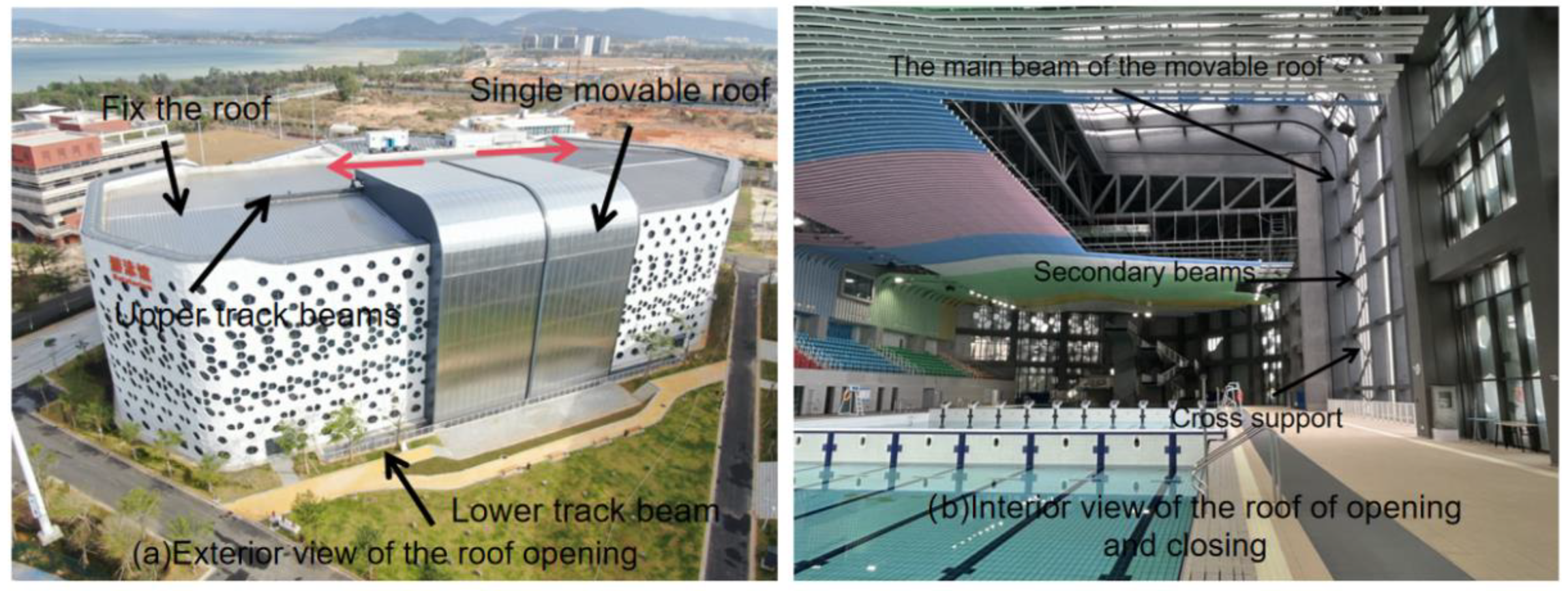
Figure 2.
Ground-Based Movable Roof Structure.
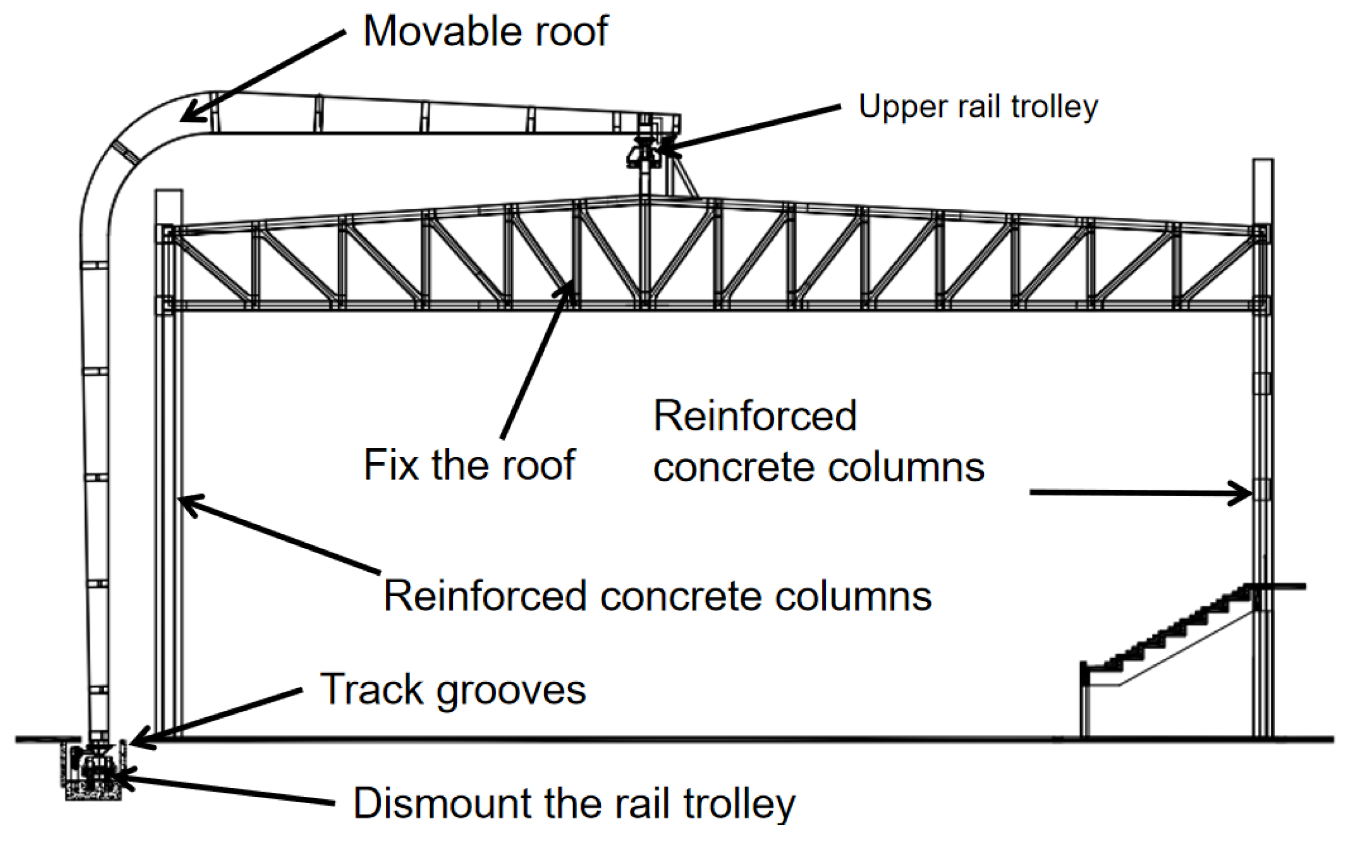
Figure 3.
Roof Lower Support Points.
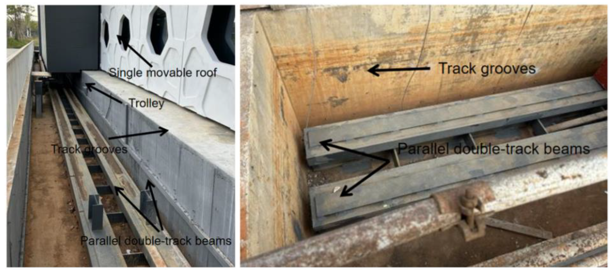
Figure 4.
Schematic Diagram of Lower Track Beam Reinforcement.
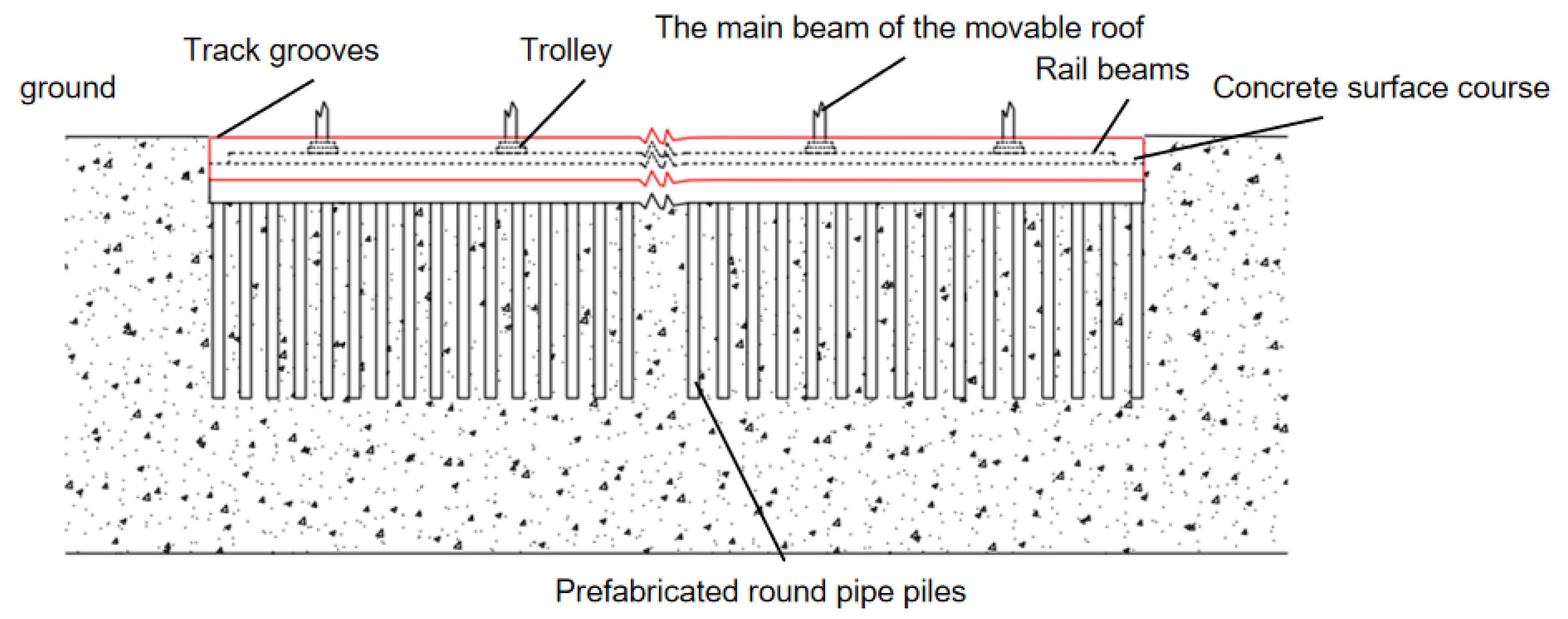
Figure 5.
Schematic Diagram of the Finite Element Software.
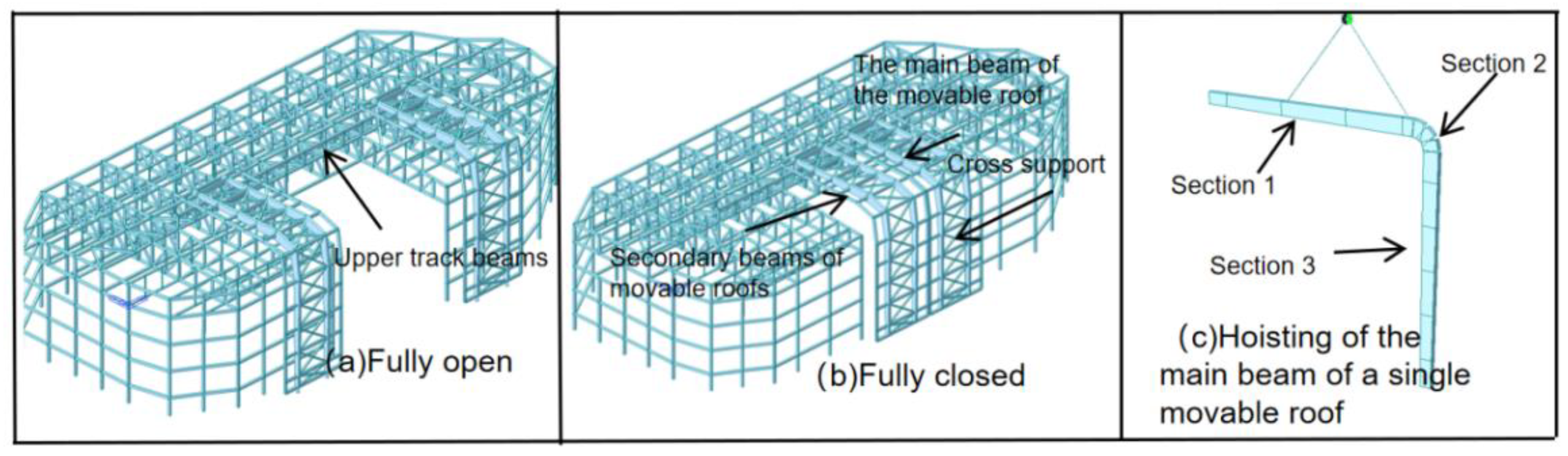
Figure 6.
Modeling of the Lower Track Beam and Its Foundation.
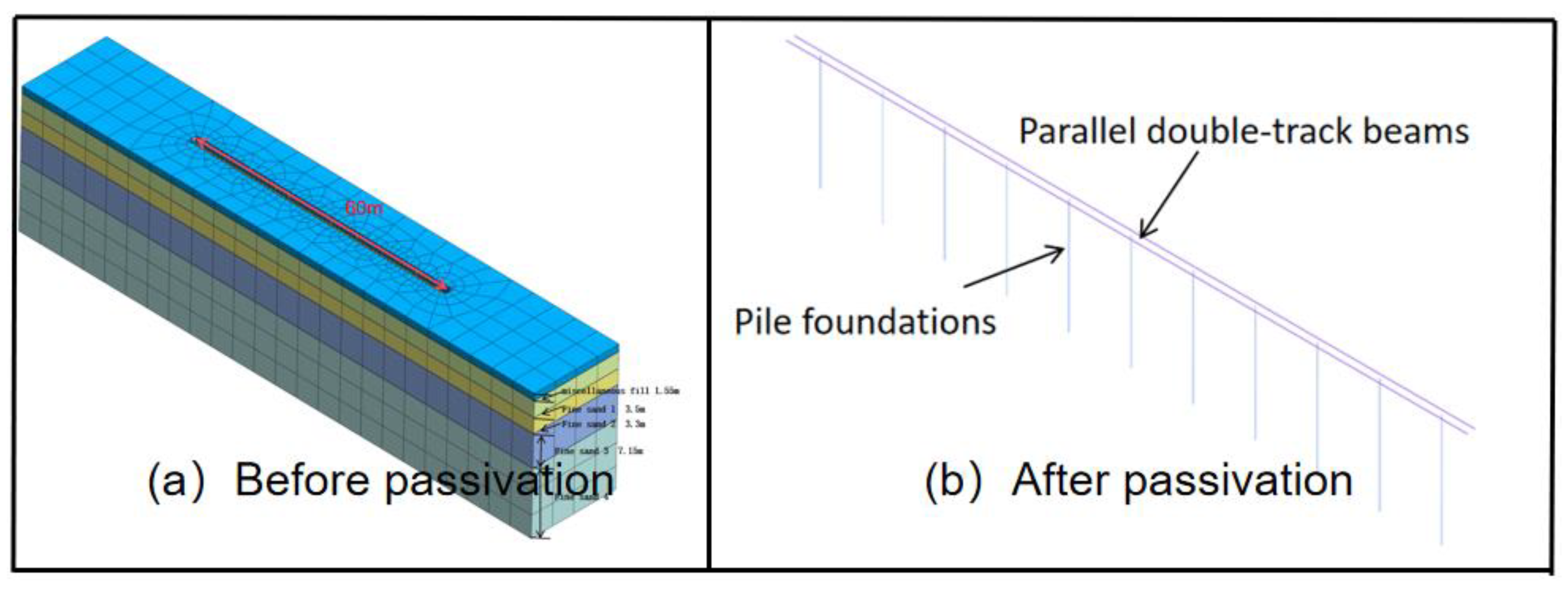
Figure 7.
Deformation Diagram of the Movable Roof Main Beam During Lifting.
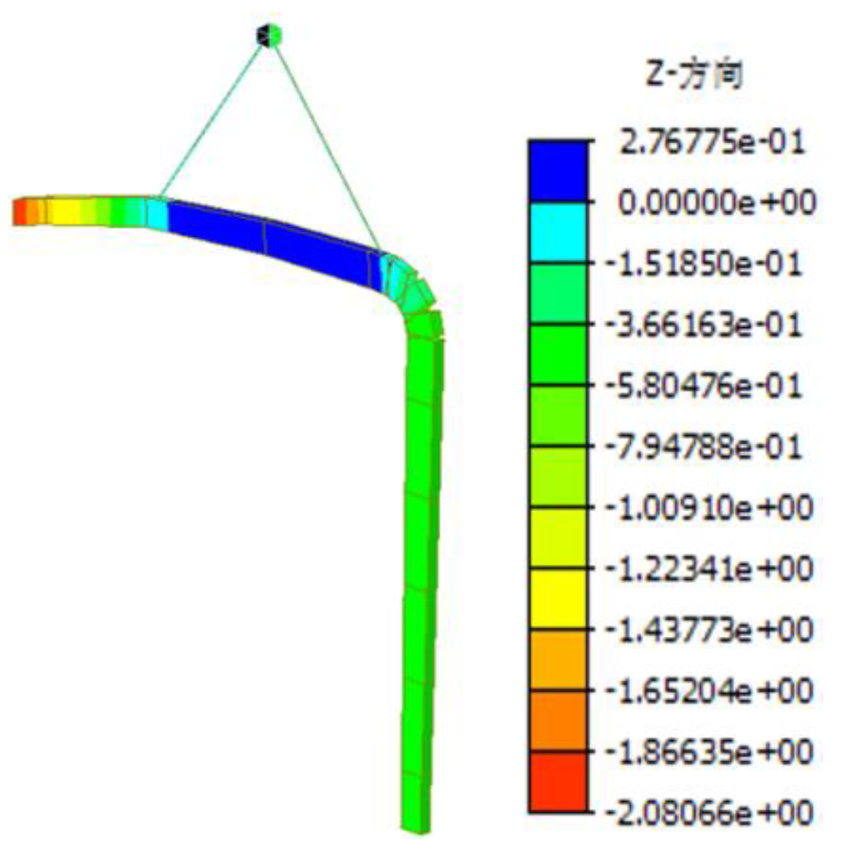
Figure 8.
Contour Plot of Vertical Displacement (Units: cm): (a) Condition 1 (b) Condition 2 (c) Condition 3 (d) Condition 4Based on the contour plots of vertical displacement under four different load conditions, the following conclusions can be drawn:.
Figure 8.
Contour Plot of Vertical Displacement (Units: cm): (a) Condition 1 (b) Condition 2 (c) Condition 3 (d) Condition 4Based on the contour plots of vertical displacement under four different load conditions, the following conclusions can be drawn:.
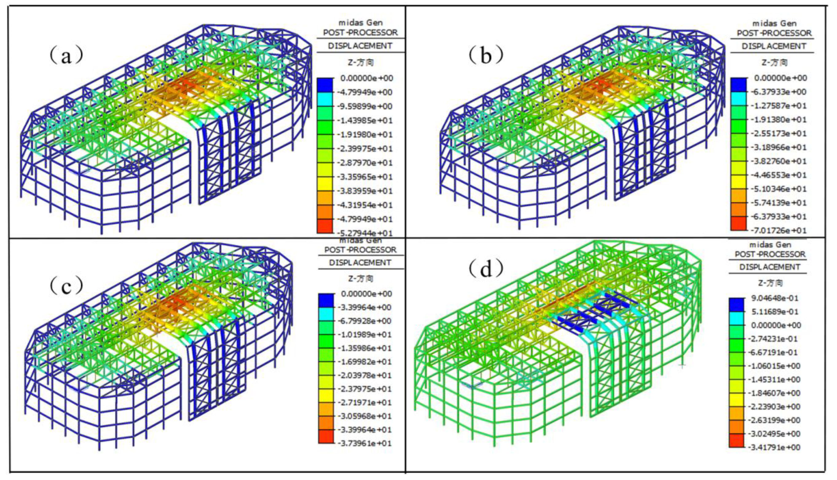
Figure 9.
First-Order Buckling Mode.
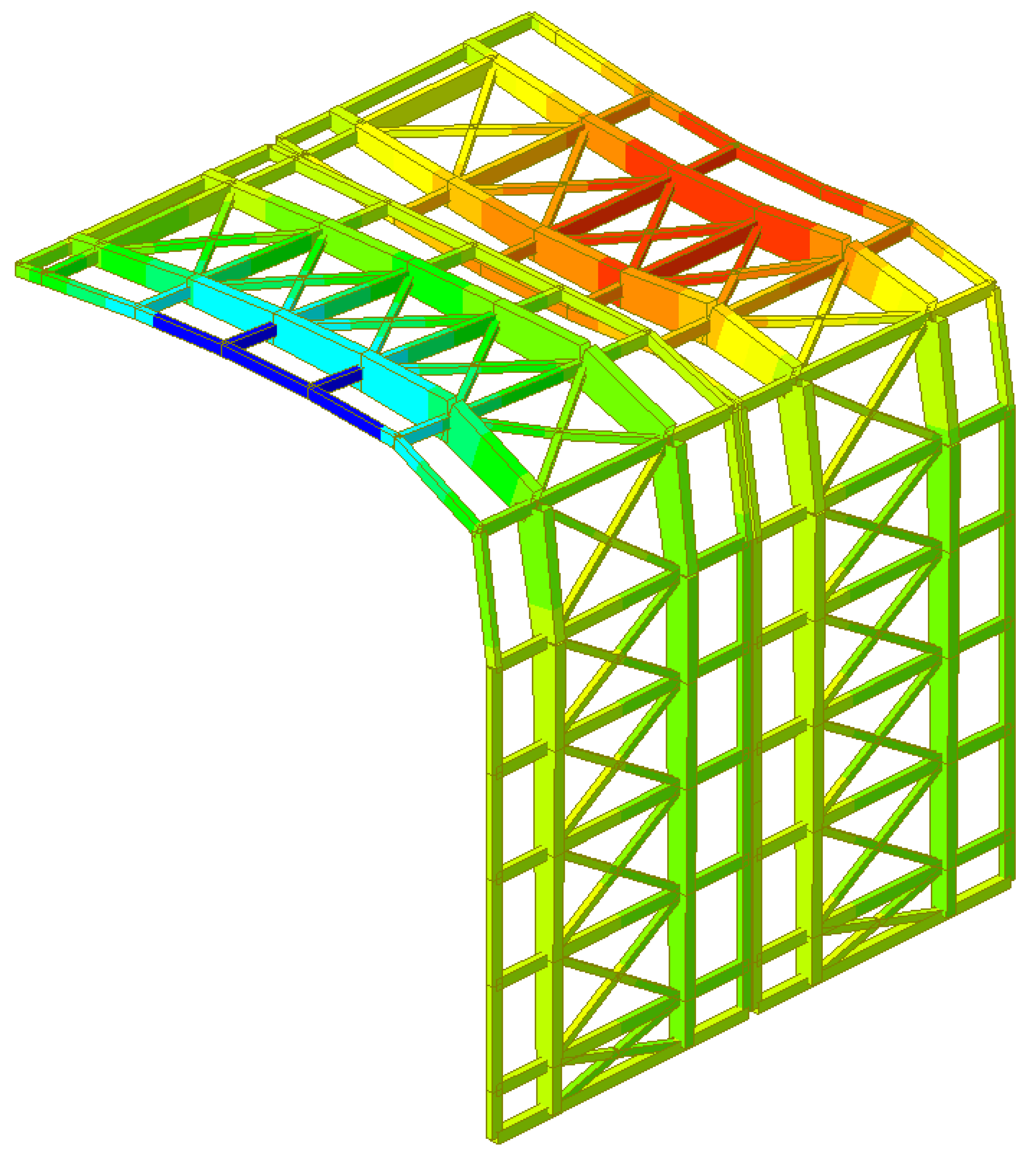
Figure 10.
Load-Displacement Curve.
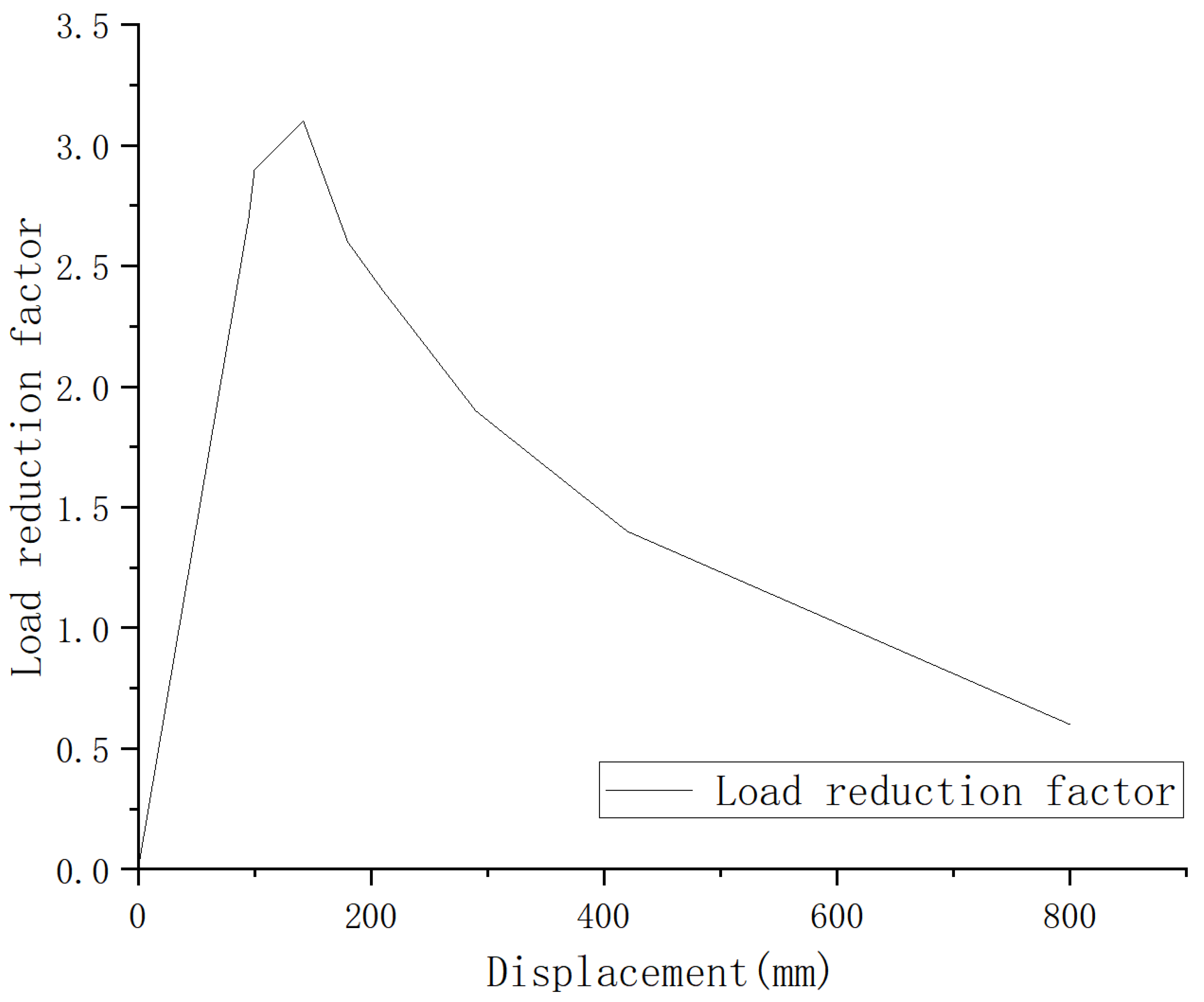
Figure 11.
Contour Plot of Vertical Displacement under Load Combinations (Units: mm): (a) 2.7 Times Load Combination; (b) 3.1 Times Load Combination.
Figure 11.
Contour Plot of Vertical Displacement under Load Combinations (Units: mm): (a) 2.7 Times Load Combination; (b) 3.1 Times Load Combination.
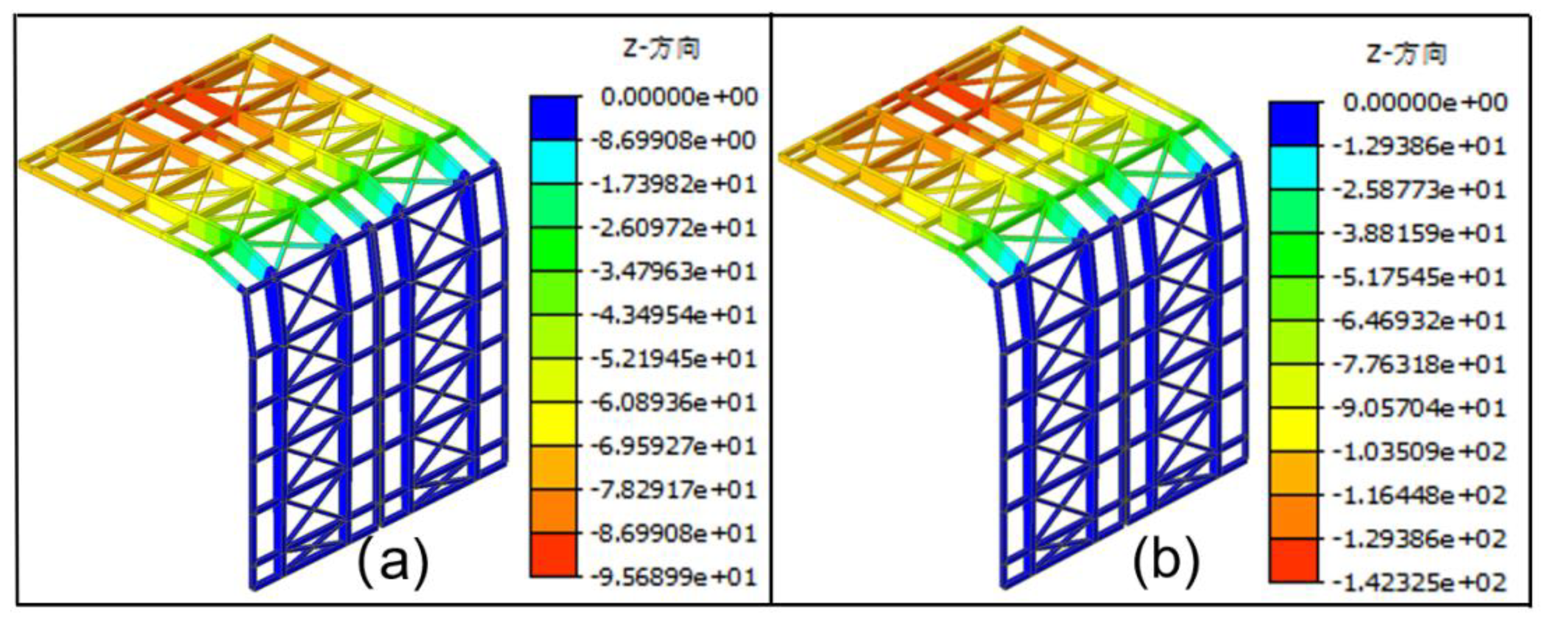
Figure 12.
Deformation Diagram of the Lower Track Beam.
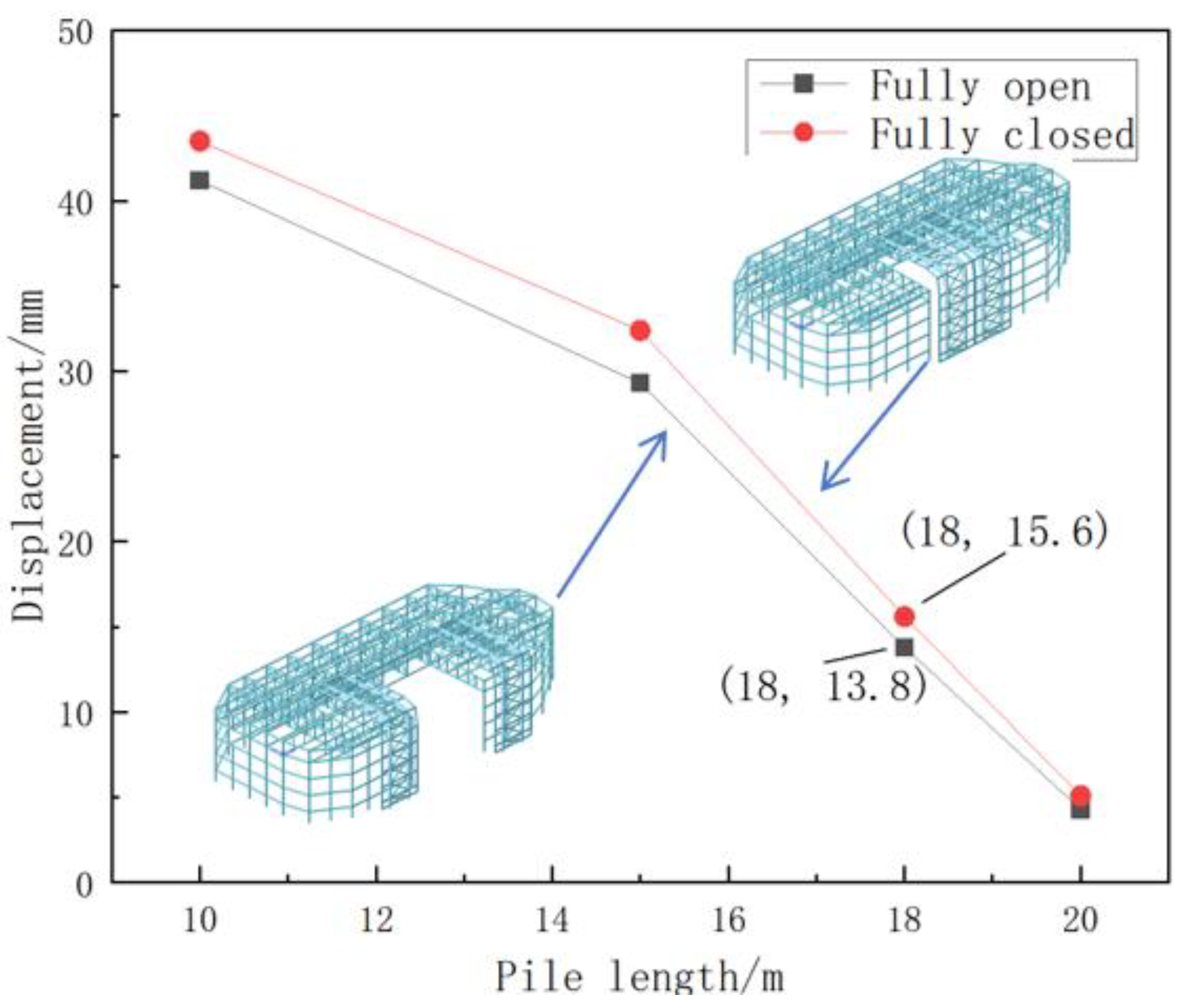
Figure 13.
Deformation Diagram of the Lower Track Beam with 18m Pile Length.
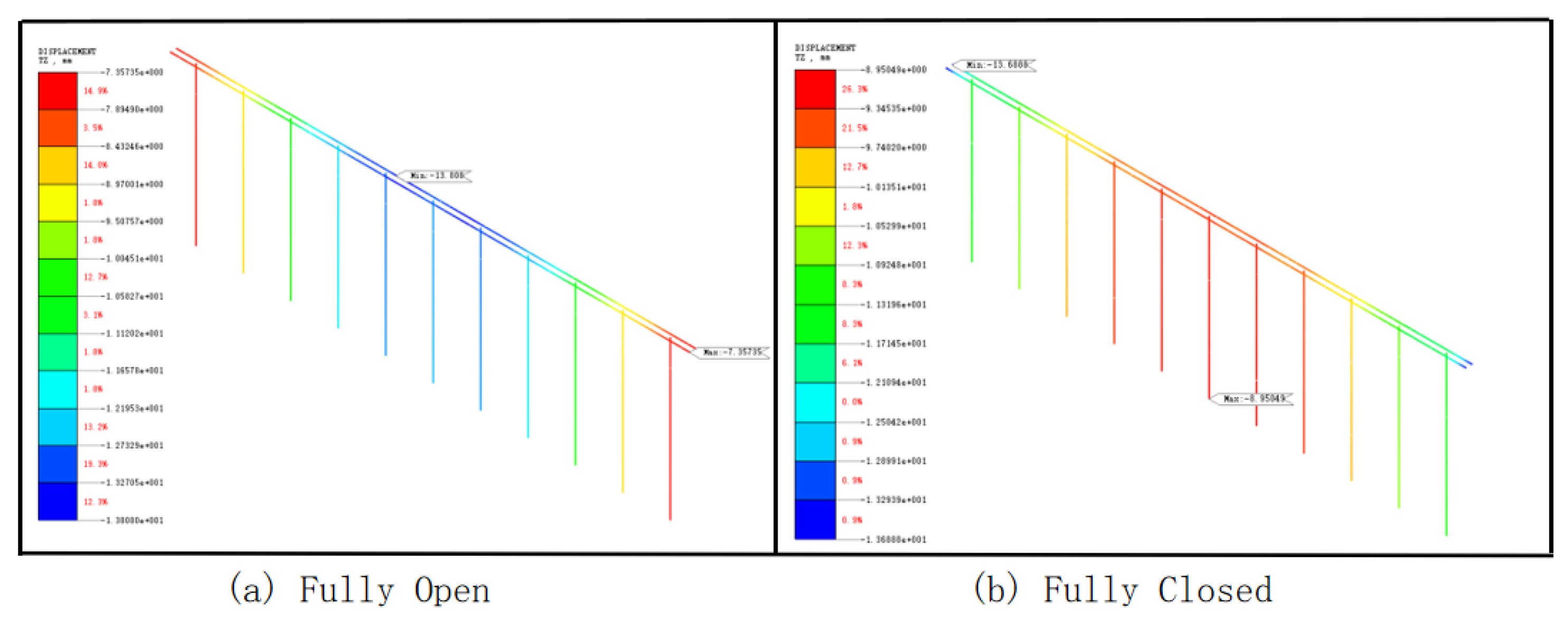

Table 1.
Component Parameters of the Opening and Closing Roof.
| Member name | Cross-section specification | Material | Cross-sectional shape |
|---|---|---|---|
| Fixed roof truss assembly | □400×400×16×16 | Q355B | Welded rectangular pipe |
| Main beam cross-section 1 of the movable roof | □1200~800×500×20×30 | Q355B | Variable cross-section welded rectangular tube |
| Main beam cross-section 2 of the movable roof | □1200~1800×500×20×30 | Q355B | Variable cross-section welded rectangular tube |
| Main beam cross-section 3 of the movable roof | □1800~800×500×20×30 | Q355B | Variable cross-section welded rectangular tube |
| Secondary beam of the movable roof | □400×300×16×16 | Q355B | Welded rectangular pipe |
| Cross bracing of the movable roof | □400×300×16×16 | Q355B | Welded rectangular pipe |
Table 2.
Soil Layer Parameters.
| Soil | Average thickness/m | Poisson's ratio | Elastic modulus/MPa | Bulk densitykN/m3 |
|---|---|---|---|---|
| Mixed fill soil | 1.55 | 0.40 | 3.00 | 15.0 |
| Fine sand 1 | 3.50 | 0.40 | 4.20 | 18.0 |
| Fine sand 2 | 3.30 | 0.35 | 6.15 | 18.5 |
| Fine sand 3 | 7.15 | 0.30 | 6.37 | 19.0 |
| Fine sand 4 | - | 0.20 | 7.68 | 19.5 |
Disclaimer/Publisher’s Note: The statements, opinions and data contained in all publications are solely those of the individual author(s) and contributor(s) and not of MDPI and/or the editor(s). MDPI and/or the editor(s) disclaim responsibility for any injury to people or property resulting from any ideas, methods, instructions or products referred to in the content. |
© 2025 by the authors. Licensee MDPI, Basel, Switzerland. This article is an open access article distributed under the terms and conditions of the Creative Commons Attribution (CC BY) license (http://creativecommons.org/licenses/by/4.0/).
Copyright: This open access article is published under a Creative Commons CC BY 4.0 license, which permit the free download, distribution, and reuse, provided that the author and preprint are cited in any reuse.


