
Submitted:
12 May 2025
Posted:
14 May 2025
You are already at the latest version
Abstract
This paper presents three realizations of a whole set of horn antenna and focusing Gradient Index (GRIN) lens in X band. The set was specifically designed for getting advance of additive manufacturing (AM) of polymers with different materials and techniques. The set has three constructive parts: a horn antenna, a support and a lens. The horn antenna is the active element and must be electrically conductive, it was manufactured with Rigid10K acrylic resin and subsequently metallised using an electroless process. The support needed to be light, robust and electrically transparent, so that Polyamide 11 (PA11) was used. The lens realization intended a dielectric material whose permittivity varies with its density. So that, we measured both dielectric permittivity and loss tangent of different polymeric materials used in AM at 2.45, 6.25 and 24.5 GHz. In addition, stochastic and gyroid mesh structures have been studied. These structures allow printing a volume that presents porosity, enabling control over the material density. Measuring the dielectric characteristics of each material with each density enables establishing graphs that relate them. The sets were then manufactured and their frequency response and radiation diagram were measured, showing excellent results when compared with literature.
Keywords:
additive manufacturing
; lattice structures
; complex permittivity
; lens design
1. Introduction
In recent years, additive manufacturing (AM) has emerged as a transformative technology with profound implications across various industries, from aerospace to healthcare, automotive, and beyond. The unique capabilities of AM—particularly in terms of material diversity, precision, and design freedom—have opened the way for novel applications in the field of communication systems. The communications industry increasingly demands higher frequency devices capable of handling the complex requirements of modern wireless systems. Additive manufacturing offers several advantages in meeting these demands. First, it enables rapid prototyping and iterative testing, allowing engineers to optimize designs in shorter time frames. This rapid design-to-manufacture process is essential for the fast-paced communications sector, where technologies are continuously evolving to support new standards like 5G and 6G. Secondly, AM facilitates the production of highly intricate structures that are difficult to machine or mold. For example, horn antennas and GRIN lenses with complex internal geometries can be manufactured as single components, reducing the need for assembly and the potential for alignment errors, which are critical in RF applications.
Antenna design has evolved significantly in response to the ever-growing demand for high-performance communication systems. Traditionally, antennas are fabricated from metals such as copper or aluminum, chosen for their high electrical conductivity and robustness in high-frequency applications. The horn antenna, a staple in RF communications, is particularly valued for its simplicity, directivity, and broadband capabilities [1]. With the advent of AM, researchers have explored new methods to create these antennas, often focusing on materials and processes that allow for high precision and reduced weight. Metallic coatings can be applied to 3D-printed polymer structures to achieve the necessary conductivity [2,3] offering a more versatile manufacturing process for complex designs. This approach not only reduces the weight of the component but also lowers material costs by limiting the use of expensive metals to surface coatings, customizing antenna properties without the constraints of conventional subtractive manufacturing. By enabling the use of composite polymer-based materials, AM also enhances the thermal management of devices, which is especially important for high-power applications in the communications field [4].
Gradient Index (GRIN) lenses are widely used in communications to manipulate the propagation of electromagnetic waves. By gradually varying the refractive index of the lens material, GRIN lenses focus or direct RF energy in a controlled manner, enhancing the performance of antennas in terms of gain and beam shaping. Traditionally, these lenses are made from homogenous dielectric materials, with their refractive index modified by altering their geometry, this often requires a labor-intensive shaping of dielectric materials to achieve the desired index gradient, which limits design flexibility and increases production time. However, AM provides the ability to adjust the refractive index more flexibly by changing the density or porosity of the polymeric material within a single component during fabrication. This method also allows for the integration of stochastic and gyroid mesh structures, which offer an additional degree of control over material properties. By adjusting the porosity of the material, designers can achieve specific permittivity values across the lens profile, as in [5,6]. This capability opens up new possibilities in lens design, enabling devices that are both lightweight and capable of complex wavefront shaping.
There are several AM techniques that are particularly suited to the polymer-based fabrication of RF components, for instance, Vat Photopolymerization (VPP) and Powder Bed Fusion (PBF). VPP, which uses ultraviolet light to selectively cure photopolymer resins, is valued for its high resolution and is often used to fabricate intricate components such as waveguides and lenses. In contrast, PBF enables the use of materials like polyamide polymer, which is lightweight and offers good mechanical stability and electrical transparency. As detailed by [7], using PBF to create support structures in RF devices enables engineers to maintain both structural integrity and desired electromagnetic transparency. The integration of these AM techniques has driven substantial advancements in the manufacture of complex antenna and lens structures, especially when complemented with material innovations like electroless metallization [8,9,10].
This article outlines the research gap existed between integration of different additive manufacturing techniques (VPP, PBF), electroless metallization and used materials (resin or nylon polymer) to develop radio frequency communication devices (previous measurements of EM properties of the material samples are accomplished in subSection 2.3. Specifically, it focuses on the development of a horn antenna and Gradient Index (GRIN) lens set, designed for operation in the X-band frequency range making use of the capabilities of AM of polymeric materials. The work begins with measuring the dielectric permittivity and loss tangent of different polymeric materials at frequencies of 2.45 (WiFi at 2.4 GHz, 3G/4G mobile bands), 6.25 (WiFi at 5 GHz, 5G mobile bands, satellite communications), and 24.5 GHz (6G mobile bands, satellite communications). Furthermore, samples of stochastic and gyroid mesh structures of the different materials were measured and the empirical relationships between material density and electromagnetic properties were established.
Then, the lens set was designed. The design of the horn antenna, lens, and support structure was tailored to their specific functional requirements, both electromagnetic and mechanical. Three realizations of the GRIN lens were produced, using the results of the characterization of polymers whose dielectric properties vary with density, allowing for a radial permittivity gradient that enhances its focusing capabilities.
The sets were then manufactured. The horn antenna, designed to be conductive, was fabricated using VPP with an acrylic resin with silica load and subsequently metallized using an electroless plating process. This combination ensures that the antenna meets the necessary conductivity specifications while benefiting from the lightweight and cost-effective nature of the polymer base. The support structure was fabricated using PBF with polyamide polymer, chosen for its mechanical stability and electrical transparency. This allows the support to maintain the structural integrity of the device without interfering with the antenna’s radiation pattern. Finally, the three GRIN lenses were manufactured using different acrylic resins and meshes with different densities radially distributed. The final assembled devices were then evaluated for frequency response and radiation pattern, yielding results that aligned well with theoretical predictions and comparable studies in existing literature.
2. Dielectric Permittivity Measurements
A material that can store energy when an external electric field is applied is known as a dielectric. Since the advent of modern communications, dielectric materials have been included in the antennas and radiofrequency (RF) components, thus the accurate measurement of their properties is crucial. The main parameter of dielectric properties is permittivity and is expressed as in Equation 1 where is called the permittivity of vacuum and is the relative permittivity of the material.
Where the permittivity of vacuum is F/m. The relative permittivity is a complex number including the real part , which shows how much energy from an external electric field is stored. Usually the term dielectric constant relates only to this real part, while the imaginary part represents how dissipative or lossy this material is to an external electric field. The ratio of the energy lost to the energy stored is called the loss tangent or , see Equation 2.
The characterization of these two parameters in new materials is essential for the proper design of devices that make use of them.
2.1. Microwave Characterization Methods
Methods for characterizing the samples can be divided into non-resonant and resonant categories. In non resonant methods, material properties are determined using reflection or reflection/transmission data in a transmission line. This data is collected via a vector network analyzer (VNA) in a wide frequency range. Transmission/reflection methods require both reflection and transmission data (scattering parameters and respectively) to determine material properties, whereas reflection methods only need reflection data (). Various transmission lines, including coaxial lines, hollow metallic waveguides, dielectric waveguides, and free space, can be utilized in these methods.
Resonant methods offer greater accuracy and sensitivity compared to non resonant methods [11], but they are restricted to one or a few discrete frequencies. These methods are divided into the methods of material under test (MUT) as a resonator and the resonant perturbation methods. The main difference between them is that in the resonant perturbation method the properties of the MUT are determined by observing changes in the properties of a resonant device with and without the MUT, whereas the MUT as a resonator method relies directly on how the MUT behaves as a resonator and which are its resonant properties. In resonant methods, the dimensions of the MUT are crucial, since they impact on the measurement, so an accurate dimensional control is required.
Three measurement methods were used in this work to characterize the AM polymeric material samples at narrow band, all of them are considered resonant perturbation methods: Resonant Coaxial Bireentrant Microwave Cavity at 2.45 GHz, Split-Cylinder Resonant Cavity at 6.25 GHz and WR42 Rectangular Waveguide at 24.5 GHz.
2.1.1. Resonant Coaxial Bireentrant Microwave Cavity
In the method described in [12], the measurements are based on how the resonant frequency and the quality factor of a resonant cavity changes when a cylindrical sample of MUT is introduced in the cavity. In order to perform the measurements we developed a stand-alone microwave instrument, the Measurement Kit consisted of a Single-Post Re-entrant Cavity for measuring cylindrical samples at resonance frequency of 2.45 GHz (mode is excited in the cavity without sample) and a VNA, as shown in Figure 1 (a). The Single-post coaxial re-entrant cavity is constructed using a coaxial transmission line. This cavity features a partially dielectric-filled gap and an endplate. To ensure alignment, a cylindrical tube housing the cylindrical sample of MUT is inserted through a hole in the endplate. It is then further inserted into the coaxial center conductor, which also serves to maintain concentricity. Measuring the reflection coefficient () of the cavity with and without the sample enables the extraction of the dielectric constant and the loss tangent, the procedure is described in detail in [13], where the circuital analysis of dielectric-loaded cylindrical waveguides and cavities is performed. The measurement instrument is presented in [14]. This equipment was used to measure the MUT at 2.45 GHz.
2.1.2. Split-Cylinder Resonant Cavity
The split-cylinder resonator is a nondestructive technique used to measure the permittivity and loss tangent of low-loss dielectric substrates. Initially proposed by Kent [15], this method utilizes a circular-cylindrical cavity divided into two halves. A planar dielectric sample is positioned in the gap between the two shorted cylindrical waveguide sections. To excite the family of resonant modes, coupling loops in the cylindrical waveguide sections are connected to the input ports of a network analyzer. By measuring the resonant frequency () and quality factor (Q) of the resonant modes, the relative permittivity and loss tangent of the sample can be determined. This procedure is based on an analytical model first developed by Michael D. Janezic and James Baker-Jarvis, [16] and [17].
The equipment used is a Split-Cylinder Cavity for measuring rectangular flat samples with resonance frequency of 6.25 GHz (mode is excited in the cavity at vacuum) and a VNA, as shown in Figure 1 (b). Then a MATLAB software was used to calculate the permittivity of the materials following the circuit analysis described in [13], with an extension of the circuital model for the circular modes in the split cavity, which can be found in [18].
2.1.3. Rectangular Waveguide
Rectangular waveguide is one of the most commonly used instruments for the measurement of dielectric properties, [19,20]. A rectangular sample of MUT, with a specified length, is placed in an empty waveguide provoking a perturbation of the electric field which is frequency dependent. By measuring the resulting and parameters, the dielectric properties of the MUT at a given frequency can be extracted. For the measurements of the work the WR42 (18–26.5 GHz) rectangular waveguide is used jointly with a VNA, as shown in Figure 2. The MUT size must be exactly the same as the X-band rectangular waveguide aperture, which is 10.668 × 4.318 mm. This measurement setup was used for the MUT characterization at 24.5 GHz .
2.2. Materials
2.2.1. Polymers for Additive Manufacturing
Traditional materials for AM, as PLA or ABS polymers used with FDM technologies, have been characterized at microwave frequencies and their dielectric constant and tangent loss are well known [21,22]. Nevertheless, the advent of new technologies and materials arises the need for analysing their dielectric properties. In this work, we have characterized six different polymers: Thought 200 and Rigid 10K resins from Formlabs, MLSA Modelling Dental resin from ApplyLabWork, Composite X resin from Liqcreate, Ultrasint PP (UPP) powder from BASF and Polyamide 11 (PA11) Bio powder from Stratasys. Dental and Thought 200 are acrylic resins used by VPP, similar to Rigid 10K and Composite X. However, these last two resins have a load of silica making them more resistant to temperature, harder and less prone to deformations. UPP is a polypropylene powder used for Multijet PBF technology, while Polyamide 11 Bio powder is a polyamide used in PBF technology.
Three different types of samples were printed in order to get the measurements at the three frequencies: a cylinder of 6.50 mm of radius and 40 mm of height for the Resonant Coaxial Bireentrant Microwave Cavity at 2.45 GHz, a flat square size 95x95x2 mm for the Split-Cylinder Resonant Cavity at 6.25 GHz and a cuboid size 10.668 × 4.318 mm and 3 mm of length for the WR42 Rectangular Waveguide at 24.5 GHz, as can be seen in Figure 3. To design the three geometries Solidworks software was used.
2.2.2. Stochastic and Gyroid Meshing
Once the solid materials were characterized, it was interesting also to measure the complex permittivity of the same materials but with different densities. The objective is to have graphs for different materials and frequencies relating density with dielectric properties. Since these properties seem to be quite constant in the frequency range, only the measurements for 2.45 and 24.5 GHz were performed. Furthermore, not all the materials were measured in this stage, since Dental and Though 200 seem to have similar properties, only Dental was used. The same happens to Polyamide 11 (PA11) and Ultrasint PP, only PA11 was measured. Composite X and Rigid 10K presented different dielectric constant, so both were measured.
The samples (cylinder and cuboid) were manufactured using porous lattices. These structures are widely used in various fields, including materials science and engineering. They can be broadly categorized into two types, both used in this work: regular lattices (gyroid mesh) and stochastic lattices (voronoi mesh). The printing densities were 25, 50 and 75 % (100 % is the solid sample), as it is shown in Figure 4. To design the gyroid mesh the Flattpack software, a freely distributed library implemented in Matlab, developed within the framework of the University of Nottingham, which allows the processing of geometrical objects by directly uploading the models to the program and processing it to obtain porous structures, is used. To design the voronoi mesh, Grasshopper 3D tool from Rhinoceros 3D commercial CAD software is used.
2.3. Permittivity Measurements
Table 1 shows the dielectric properties of the different materials for the three frequencies. The materials show very slight differences with frequency, indicating that within the microwave bandwidth, the dielectric properties are stable. As expected, materials containing silica in the resin (Rigid 10K and Composite X) present higher dielectric constant and materials made up from polymer powder (UPP and PA11) a lower one. The same behaviour is observed in the material density, which at the end will be translated to the weight of the final printed item.
Regarding the porous samples, Table 2 shows the results for the materials at the two extreme frequencies. The samples were manufactured with gyroid or voronoi meshes. From these data, the graphs in Figure 5 were extracted, enabling a wide range of permittivities within the same material.
Measuring the dielectric properties at 24.5 GHz presents a technological challenge, as methods such as the bi-reentrant cavity and split cylinder do not provide reliable results due to the small size of the samples and cavities and manufacturing tolerances. Although the rectangular waveguide method is very reliable for characterizing the dielectric constant, its uncertainty in calculating the loss tangent is intolerable, so that the results of loss tangent at that frequency are missing in this study.
3. Horn Antenna and Gradient Index Lens Design
The objective of the design was to get a complete set of horn antenna and GRIN lens that meets certain electromagnetic and mechanical specifications. The main idea behind GRIN lens is that it focuses the radiation pattern of a radiating element, enhancing the directivity of the set. In this general approach, two main elements must be designed, on the one hand the radiating element, on the other hand the lens. The electromagnetic design is frequency dependant, but scalable, allowing a design developed for one frequency to be easily adjusted for another. The selected working frequency for the set is 10 GHz, covering services in X band satellite communications. On the other hand, mechanical issues have to be considered as the weight of the set and how the radiation element and the lens are built up together in order to get a compact element ready to be used.
3.1. Electromagnetic Design
3.1.1. Horn Antenna
The radiating element is located in the focal point of the set. For the type of communication services the set is intended (satellite) the whole system may handle high power and require low loss, the optimal technology in that case is waveguide, either rectangular or circular. Traditionally horn antennas have been used together with waveguides due to easiness of integration and high efficiency. In this case, we have designed a conic horn with the objective to achieve a good balance between illumination efficiency and spillover efficiency. The criterion adopted was that the electromagnetic field level radiated by the horn at the edges of the lens should be 10 dB below the maximum, ensuring an optimal balance between illumination efficiency and spillover efficiency, thereby maximizing the total efficiency of the system. The sketch with the dimensions of the horn is presented in Figure 6 (a) and (b), and the values are provided in Table 3.
3.1.2. Gradient Index Lenses
The design of the lens covered several stages, first of all some parameters were chosen in order to meet sensible size and weight of the whole set, then an Adjoint Method, see [23] was used to get the permittivity values depending on the radius.
The focal point was chosen such that , pointing that the focal length is equal to the diameter of the lens. For practical purposes, the diameter of the lens was D=15 cm, and its width H=2.5 cm. That would provide a realizable lens with a low cost AM printer. However, the achievable range of permittivity values was constrained by the available materials and the limitations of the additive manufacturing process. Specifically, printing densities below 20% were avoided to maintain the structural integrity of the lens. Consequently, the feasible permittivity values ranged from to , where represents the relative dielectric constant of the material at 100% density.
On the other hand, we can not count with all possible ranges of permittivity, since we were linked to the available materials and the limitations of printers, a printing density lower than 20 % would endanger the structural integrity of the lens. So that the possible values ranged from to 0.2(-1)+1, where is the relative dielectric constant of the material printed at 100 % density.
The optimization process determines the optimal distribution of within a rectangular domain of height D and width H. This domain is divided into 11 regions, resulting on 11 levels of freedom where is constant within each region. The optimization objective was to have a maximum electromagnetic field in the focal point. We used our own optimization program to obtain different realizations of the lens. The sketch representing the lens with sectors and corresponding values of permittivity are presented in Figure 6 (d). It is worth mentioning that the optimized and manufactured lenses present a central cylindrical sector with a radius of 12.5 mm (which corresponds to the permittivity ) and then the five successive concentric rings have a thickness of 12.5 mm.
The optimizer achieved three different results: a flat heterogeneous lens design which is consistent with a standard result, referred to as lens A (Figure 9 (a)); an airy disk pattern, lens B (Figure 9 (b)); and a ring pattern, lens C (Figure 9 (c)). The values of the relative dielectric constant for the different sectors of the three realizations is shown in Table 4. Both lens B and C present patterns associated with Fraunhoffer diffraction through circular apertures.
The simulated directivity of the horn antenna and the set with the three different lens, using CST Dassault Systems Suite, is presented in Figure 7
3.2. Mechanical Design
The feeding horn antenna and the lens needed to be assembled using a mechanical support. The support was required to provide structural resistance, be transparent from an electromagnetic perspective, and promote the modularity of the system, as it needed to allow the exchange of the three types of lenses. The dimensions of the support are outlined in Figure 6.(c) and their values are given in Table 3. A four-piece design was chosen, with the pieces connected by pegs, allowing for easy assembly and disassembly. Additionally, to reduce the weight of the support while maintaining its structural resistance, it was designed as a series of rods connected by St. Andrew’s crosses, as shown in Figure 8. The mechanical supports were designed using Solidworks software.
4. Prototype Manufacturing
4.1. Additive Manufacturing
The assembly of horn antenna, the lens, and the support is additively manufactured. Different materials and technologies will be used for each piece, depending on their characteristics.
The designed RF feeding element, the X-band conical horn antenna, was manufactured using Vat Photopolymerization technology with curing by exposure to ultraviolet laser beam with acrylic resin (VPP) with the printer Form 3BL of Formlabs, resin Rigid10K was used. The piece then underwent the process of sandblasting and metallization, the manufactured part is presented in Figure 8 (a), before metallization, and (b), after the metallization process.
The three realizations of the lenses were manufactured with different materials, depending on their required dielectric constants. The lens A was printed using Composite X resin; the lens B was printed using Dental resin; and two prototypes of the lens C were manufactured, one made in Composite X and another in Rigid 10K, all of them printed using Vat Photopolymerization technology with curing by exposure to ultraviolet laser beam with acrylic resin (VPP). All of the prototypes are presented in Figure 9.
Concerning the supports, we manufactured them with two different powder materials: PA11 printed with Stratasys SAF 350 equipment, and UPP printed with HP Multi Jet Fusion 5200 3D. These materials were chosen for their lightness, low permittivity and good mechanical performance. In both cases, their mechanical and electromagnetic performances were similar. The assemblies using both PA11 and UPP mechanical supports are presented in Figure 8 (c).
4.2. Metallization Process
The feeding horn antenna, must be a conductive element, so it must be coated with a homogeneous layer of electrically conductive material. This was done using two successive electroless coating processes of nickel and copper, [24]. This method uses a chemical reaction to bond particles of the desired metal to the surface of the polymer pieces, [25], without the use of an electric current.
Initially, the surface of the piece must be prepared to allow strong bonding with the metal deposition. The most common method for this involves chemical etching with strong oxidizing compounds such as chromium salts, highly corrosive and polluting. In this work, the chromium salt etching was replaced by a combination of a first shot blasting and a subsequent chemical etching with sodium hydroxide solution. Then, a catalytic layer of palladium is deposited on the surfaces of the pieces by immersion in an activating bath consisting of a and acidic solution, as described in [26]. Before the final metallization bath, an acceleration step is performed by treating the sample in an acidic solution to remove the non-reacted salts and the , and expose the to the autocatalytic reaction. This layer is responsible for initiating the chemical reduction reaction in which the metal adheres to the surface.
The initial nickel coating process results in a relatively uniform and stable metallic deposition, although it may leave some small uncovered areas, particularly in the corners. Despite the uniformity of the layer, the nickel coating presents very low conductivity, so an additional copper bath is applied to fix minor defects and increase the conductivity.
5. Results
The electromagnetic response of the assembled prototypes was evaluated in an anechoic chamber, with the experimental setup depicted in Figure 10. The directivities of the different lens antennas were measured and their results are given in Figure 11. When comparing to the simulated directivities, it can be stated that all the lens antennas achieved directivities near 20 dB, with lens A around 19,5 dB, and with lenses B and C up to 22 dB, even more than the simulated expected results.
Additionally, the lenses, as well as the horn antenna and the supports, have been weighed, with the results presented in the Table 5. As shown, both the horn antenna and the supports are very light, with the lens providing the main contribution to the overall weight. The total weight of the sets ranges from approximately 500 g for lens A to 280 g for lens C.
Table 6 displays the results of our three lenses compared to recent literature. The main conclusion is that the lenses present similar measured directivity, lenses B and C present similar or better efficiency compared to the lenses with similar size, but with an important reduction in thickness, which substantially decreases the volume of the whole set. This is achieved by using variable densities of the printing material in different sectors with consistent thickness, instead of varying the lens thickness — a traditional approach for these lenses. This approach also enhances lens efficiency, as evidenced by our measured results.
6. Conclusions
In conclusion, the exploration of AM for fabricating complex RF components—such as horn antennas and GRIN lenses—is not only feasible but also advantageous for the communications industry. By enabling the integration of lightweight, customizable, and precisely engineered polymer structures with metalized conductive elements, AM provides a versatile platform for advanced RF device design. The ability to control material properties and topology on a fine scale, particularly for gradient-index lenses, represents a key advancement in wave manipulation and antenna performance.
As the field of AM continues to evolve, its application in communications is likely to expand, supporting the development of more sophisticated, compact and efficient systems across a range of frequencies and applications.
Author Contributions
For research articles with several authors, a short paragraph specifying their individual contributions must be provided. The following statements should be used “Conceptualization, F.V. and C.B.; methodology, C.B.; software, A.V and F.V and L.S.; validation, F.V., F.P. and R.K.; formal analysis, F.V.; investigation, A.V. and A.F.; resources, C.B.; data curation, A.V.; writing—original draft preparation, A.V.; writing—review and editing, C.B.; visualization, A.V.; supervision, C.B. and F.V.; project administration, F.V.; funding acquisition, C.B. All authors have read and agreed to the published version of the manuscript.”, please turn to the CRediT taxonomy for the term explanation. Authorship must be limited to those who have contributed substantially to the work reported.
Funding
This research received no external funding.
Acknowledgments
This work has been funded by Agencia Valenciana de la Innovación through the research project INNEST/2022/124, European Union NextGenerationEU/PRTR Project TED2021-129196B-C41/ AEI/10.13039/501100011033/, FEDER, UE Project PID2022-136590OB-C41/ AEI/10.13039/501100011033/, European Union NextGenerationEU project PRTR-C17.I1 as part of the Advanced Materials program supported by Ministerio de Ciencia e Innovación, Generalitat Valenciana project: MAOCOM-6G, Code: MFA/2022/056 and Ministerio de Ciencia e Innovación project PID2022-136869NB-C33.
Abbreviations
The following abbreviations are used in this manuscript:
GRIN Gradient Index
AM Additive Manufacturing
RF Radio Frequency
VPP Vat Photopolymerization
PBF Powder Bed Fusion
VNA Vector Network Analyzer
MUT Material Under Test
SLA Stereolithography
FFF Fused Filament Fabrication
OEWG Open End Waveguide
References
- Balanis, C.A. Antenna Theory : Analysis and Design., 4th ed. ed.; John Wiley and Sons, Incorporated: Hoboken, 2016.
- Sharifi, J.; Paserin, V.; Fayazfar, H.R. Sustainable direct metallization of 3D-printed metal-infused polymer parts: a novel green approach to direct copper electroless plating. Advances in Manufacturing 2024, 12, 784–797. [CrossRef]
- Shen, J.; Aiken, M.; Ladd, C.; Dickey, M.D.; Ricketts, D.S. A simple electroless plating solution for 3D printed microwave components. 2016 Asia-Pacific Microwave Conference (APMC) 2016, pp. 1–4. [CrossRef]
- Lupone, F.; Padovano, E.; Casamento, F.; Badini, C. Process Phenomena and Material Properties in Selective Laser Sintering of Polymers: A Review. Materials 2022, 15. [CrossRef]
- Wang, W.; Lambert, P.; Chisum, J. High-Frequency Limits for 3D-Printed Gradient-Index (GRIN) Lens Antennas. 2023 IEEE International Symposium on Antennas and Propagation and USNC-URSI Radio Science Meeting (USNC-URSI) 2023, pp. 1695–1696. [CrossRef]
- Davis, B.; Wang, W.; Versluys, E.; Gargitter, V.; Ramberg, H.; Chisum, J. Hybrid Additive-Manufactured Gradient-Index Lenses with Low-Profile and High Efficiency. 2024 IEEE International Symposium on Antennas and Propagation and INC/USNC-URSI Radio Science Meeting (AP-S/INC-USNC-URSI) 2024, pp. 543–544. [CrossRef]
- Yehia, H.M.; Hamada, A.; Sebaey, T.A.; Abd-Elaziem, W. Selective Laser Sintering of Polymers: Process Parameters, Machine Learning Approaches, and Future Directions. Journal of Manufacturing and Materials Processing 2024, 8. [CrossRef]
- Lomakin, K.; Sippel, M.; Helmreich, K.; Gold, G. Design and Analysis of 3D Printed Slotted Waveguides for D-Band using Stereolithography and Electroless Silver Plating. 2020 IEEE/MTT-S International Microwave Symposium (IMS) 2020, pp. 177–180. [CrossRef]
- Le Sage, G.P. 3D Printed Waveguide Slot Array Antennas. IEEE Access 2016, 4, 1258–1265. [CrossRef]
- Li, J.; Wu, S.; Li, Y.; Chen, X.; Yan, S.; Zhang, X.Y. SLA Printed Dual-Band Conical-Beam Filtering Antenna. IEEE Antennas and Wireless Propagation Letters 2023, 22, 2462–2466. [CrossRef]
- Krupka, J. Frequency domain complex permittivity measurements at microwave frequencies. Measurement Science and Technology 2006, 17, R55. [CrossRef]
- Riddle, B.F.; Baker-Jarvis, J. Dielectric measurements using a reentrant cavity: mode-matching analysis. Technical Note (NIST TN), National Institute of Standards and Technology, Gaithersburg, MD 1996.
- Peñaranda-Foix, F.L.; Janezic, M.D.; Catala-Civera, J.M.; Canos, A.J. Full-Wave Analysis of Dielectric-Loaded Cylindrical Waveguides and Cavities Using a New Four-Port Ring Network. IEEE Transactions on Microwave Theory and Techniques 2012, 60, 2730–2740. [CrossRef]
- Gutiérrez-Cano, J.D.; Plaza-González, P.; Canós, A.J.; García-Baños, B.; Catalá-Civera, J.M.; .; Peñaranda-Foix, F.L. A New Stand-Alone Microwave Instrument for Measuring the Complex Permittivity of Materials at Microwave Frequencies. IEEE Transactions on Instrumentation and Measurement 202o, 69, 3995–3605. [CrossRef]
- Kent, G. An evanescent-mode tester for ceramic dielectric substrates. IEEE Transactions on Microwave Theory and Techniques 1988, 36, 1451–1454. [CrossRef]
- Janezic, M.; Baker-Jarvis, J. Full-wave analysis of a split-cylinder resonator for nondestructive permittivity measurements. IEEE Transactions on Microwave Theory and Techniques 1999, 47, 2014–2020. [CrossRef]
- Janezic, M.; Kuester, E.; Jarvis, J. Broadband complex permittivity measurements of dielectric substrates using a split-cylinder resonator. In Proceedings of the 2004 IEEE MTT-S International Microwave Symposium Digest (IEEE Cat. No.04CH37535), 2004, Vol. 3, pp. 1817–1820 Vol.3. [CrossRef]
- Marqués-Villarroya, D.; Peñaranda-Foix, F.L.; García-Baños, B.; Catalá-Civera, J.M.; Gutiérrez-Cano, J.D. Enhanced Full-Wave Circuit Analysis for Modeling of a Split Cylinder Resonator. IEEE Transactions on Microwave Theory and Techniques 2017, 65, 1191–1202. [CrossRef]
- Nicolson, A.M.; Ross, G.F. Measurement of the Intrinsic Properties of Materials by Time-Domain Techniques. IEEE Transactions on Instrumentation and Measurement 1970, 19, 377–382. [CrossRef]
- Baker-Jarvis, J.; Vanzura, E.; Kissick, W. Improved technique for determining complex permittivity with the transmission/reflection method. IEEE Transactions on Microwave Theory and Techniques 1990, 38, 1096–1103. [CrossRef]
- Amudhu, L.B.T.; Samsingh, R.V.; Florence, S.E.; Prakash, C.A. Electromagnetic wave absorption and mechanical properties of 3D-printed PLA composite reinforced with graphene and iron (III) oxide for X-band absorbers. Journal of Materials Science: Materials in Electronics 2024, 35, 1273. [CrossRef]
- Felício, J.M.; Fernandes, C.A.; Costa, J.R. Complex permittivity and anisotropy measurement of 3D-printed PLA at microwaves and millimeter-waves. 2016 22nd International Conference on Applied Electromagnetics and Communications (ICECOM) 2016, pp. 1–6. [CrossRef]
- Vico, F.; Jimènez, L.; Cabedo-Fabrés, M.; Bachiller, C.; Voronov, A. Designing X-Band Lenses With the Adjoint Method and 3D Printing Techniques. IEEE Open Journal of Antennas and Propagation 2025, pp. 1–1. [CrossRef]
- Bachiller, C.; Ferrer, A.; Voronov, A.; Capella, M.; Bosca, F.; Marin, M.L.; Sempere, L.; Kunowsky, M.; Martinez-Garcia, A. Characterization of the Effective Conductivity in Radio Frequency of Additive Manufacturing Materials. Radio Science 2025, 60. [CrossRef]
- Nova, V.; Bachiller, C.; Pascual-Folch, J.; Ferrer, A.; Ponce-Gonzalez, L.N.; Marin, M.; Esbert, V.E.B. 3-D Printed Waveguide Filters: Manufacturing Process and Surface Mounted Assembly. IEEE Transactions on Microwave Theory and Techniques 2023, 71. [CrossRef]
- Moraczewski, K.; Malinowski, R.; Rytlewski, P.; Zenkiewicz, M. Autocatalytic metallization of polylactide. Polimery 2015, 60, 492–500. [CrossRef]
- Zhang, S.; Arya, R.K.; Pandey, S.; Vardaxoglou, Y.; Whittow, W.; Mittra, R. 3D-printed planar graded index lenses. IET Microwaves, Antennas and Propagation 2016, 10, 1411–1419. [CrossRef]
- Paraskevopoulos, A.; Maggiorelli, F.; Gashi, I.; Giovampaola, C.D.; Albani, M.; Maci, S. 3-D Printed All-Dielectric GRIN Lens Antenna With an Integrated Feeder. IEEE Open Journal of Antennas and Propagation 2023, 4, 528–536. [CrossRef]
- Poyanco, J.M.; Pizarro, F.; Rajo-Iglesias, E. 3D-printed dielectric GRIN planar wideband lens antenna for 5G applications, 2021. [CrossRef]
- Poyanco, J.M.; Pizarro, F.; Rajo-Iglesias, E. Cost-effective wideband dielectric planar lens antenna for millimeter wave applications. Scientific Reports 2022, 12, 4204. [CrossRef]
- Zhang, S.; Arya, R.K.; Whittow, W.G.; Cadman, D.; Mittra, R.; Vardaxoglou, J.C. Ultra-Wideband Flat Metamaterial GRIN Lenses Assisted With Additive Manufacturing Technique. IEEE Transactions on Antennas and Propagation 2021, 69, 3788–3799. [CrossRef]
- Papathanasopoulos, A.; Budhu, J.; Rahmat-Samii, Y.; Hodges, R.E.; Ruffatto, D.F. 3-D-Printed Shaped and Material-Optimized Lenses for Next-Generation Spaceborne Wind Scatterometer Weather Radars. IEEE Transactions on Antennas and Propagation 2022, 70, 3163–3172. [CrossRef]
- Whiting, E.B.; Mackertich-Sengerdy, G.; Campbell, S.D.; Soltani, S.; Haack, M.P.; Barrett, J.P.; Withrow, J.W.; Bossard, J.A.; Werner, D.H. Adjoint Sensitivity Optimization of Three-Dimensional Directivity-Enhancing, Size-Reducing GRIN Lenses. IEEE Antennas and Wireless Propagation Letters 2022, 21, 2166–2170. [CrossRef]
- Garcia-Marin, E.; Filipovic, D.S.; Masa-Campos, J.L.; Sanchez-Olivares, P. Ka-band Multi-beam Planar Lens Antenna for 5G Applications, 2020. [CrossRef]
- Zhang, S.; Liu, P.; Whittow, W. Design and Fabrication of 3-D-Printed High-Gain Broadband Fresnel Zone Lens Using Hybrid Groove-Perforation Method for Millimeter-Wave Applications. IEEE Antennas and Wireless Propagation Letters 2022, 21, 34–38. [CrossRef]
Figure 1.
Measurement Equipment (a). Single-Post Re-entrant Cavity Measurement Kit at 2.45 GHz (b). Split-Cylinder Resonant Cavity Measurement Kit at 6.25 GHz
Figure 1.
Measurement Equipment (a). Single-Post Re-entrant Cavity Measurement Kit at 2.45 GHz (b). Split-Cylinder Resonant Cavity Measurement Kit at 6.25 GHz
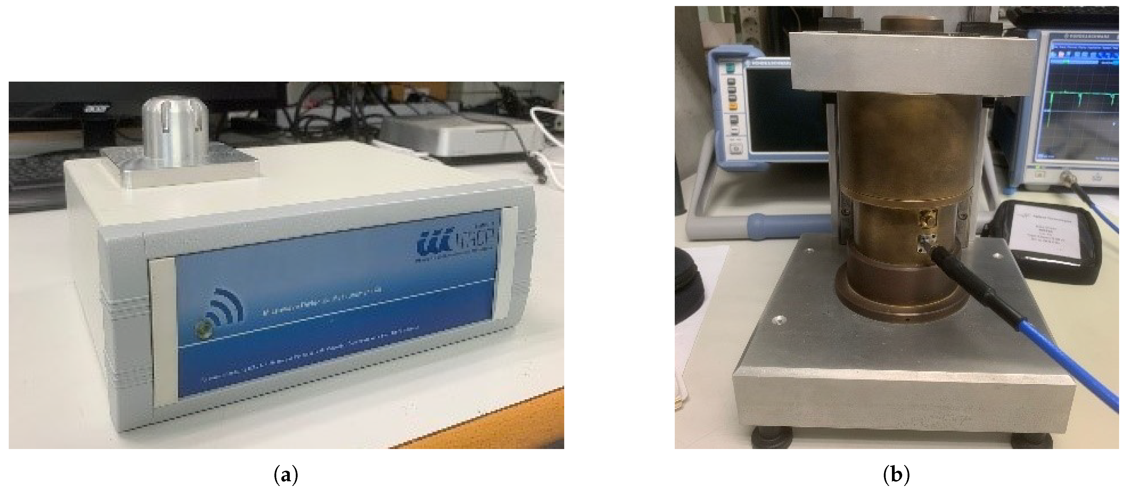
Figure 2.
WR42 Rectangular Waveguide Measurement Kit at 24.5 GHz
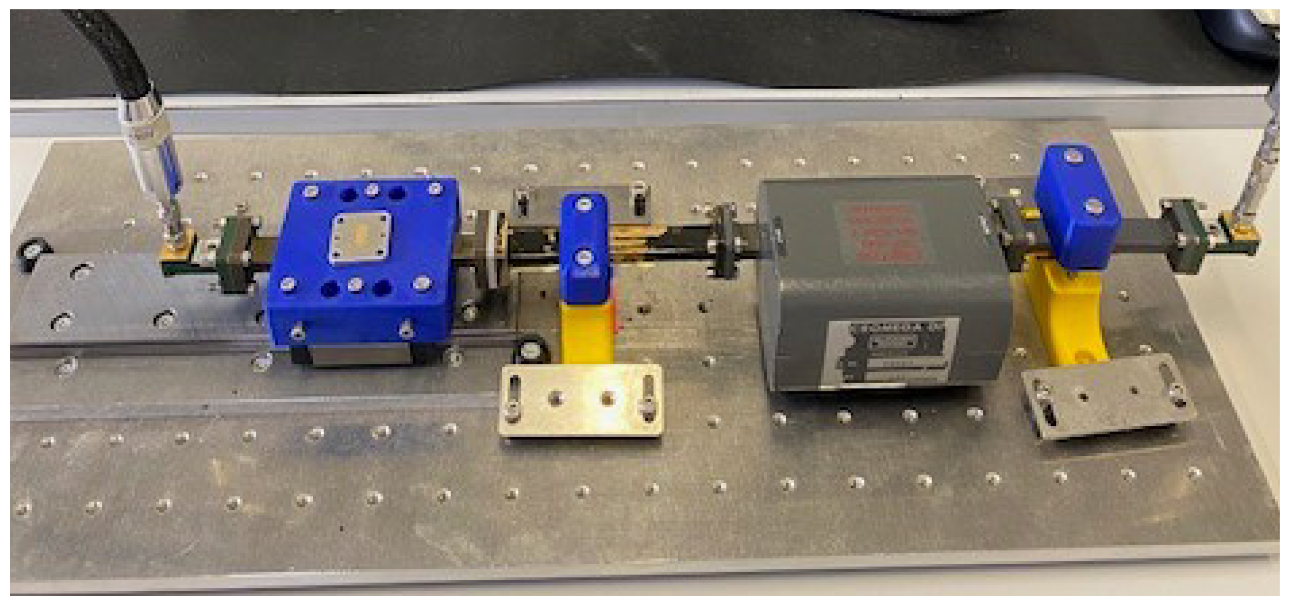
Figure 3.
Solid Samples of PA11, Dental and Rigid 10K materials.
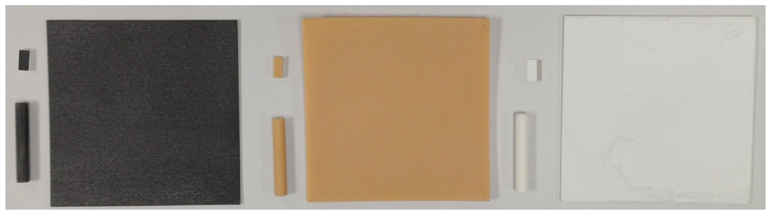
Figure 4.
Cylindrical Rigid 10K samples (a). Gyroid mesh (b). Voronoi mesh
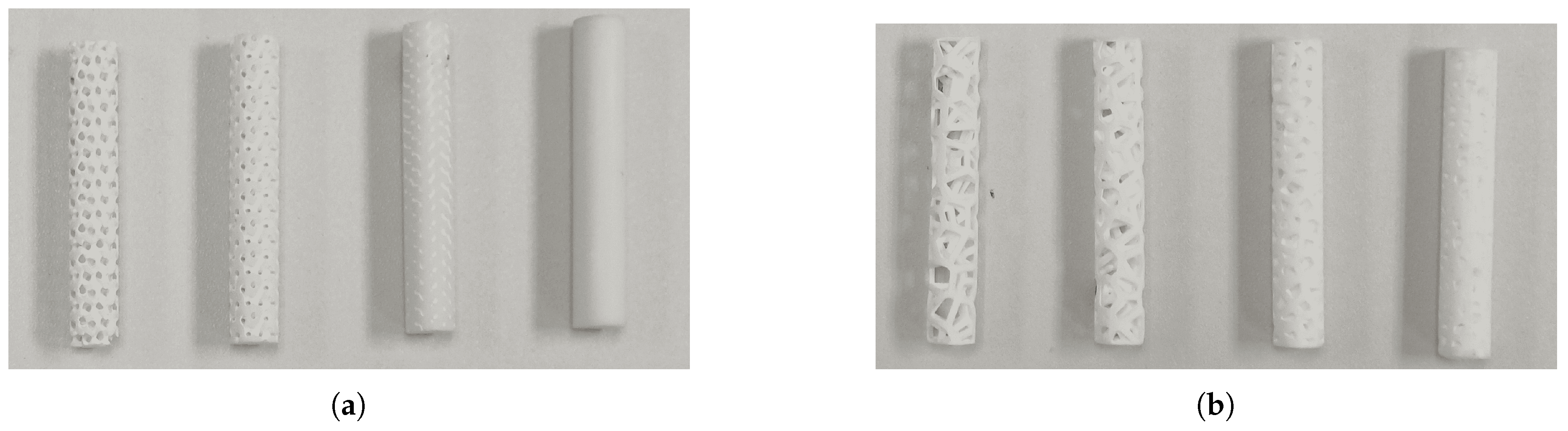
Figure 5.
Variable Density Sample Measurements (a). At 2.45 GHz (b). At 24.5 GHz
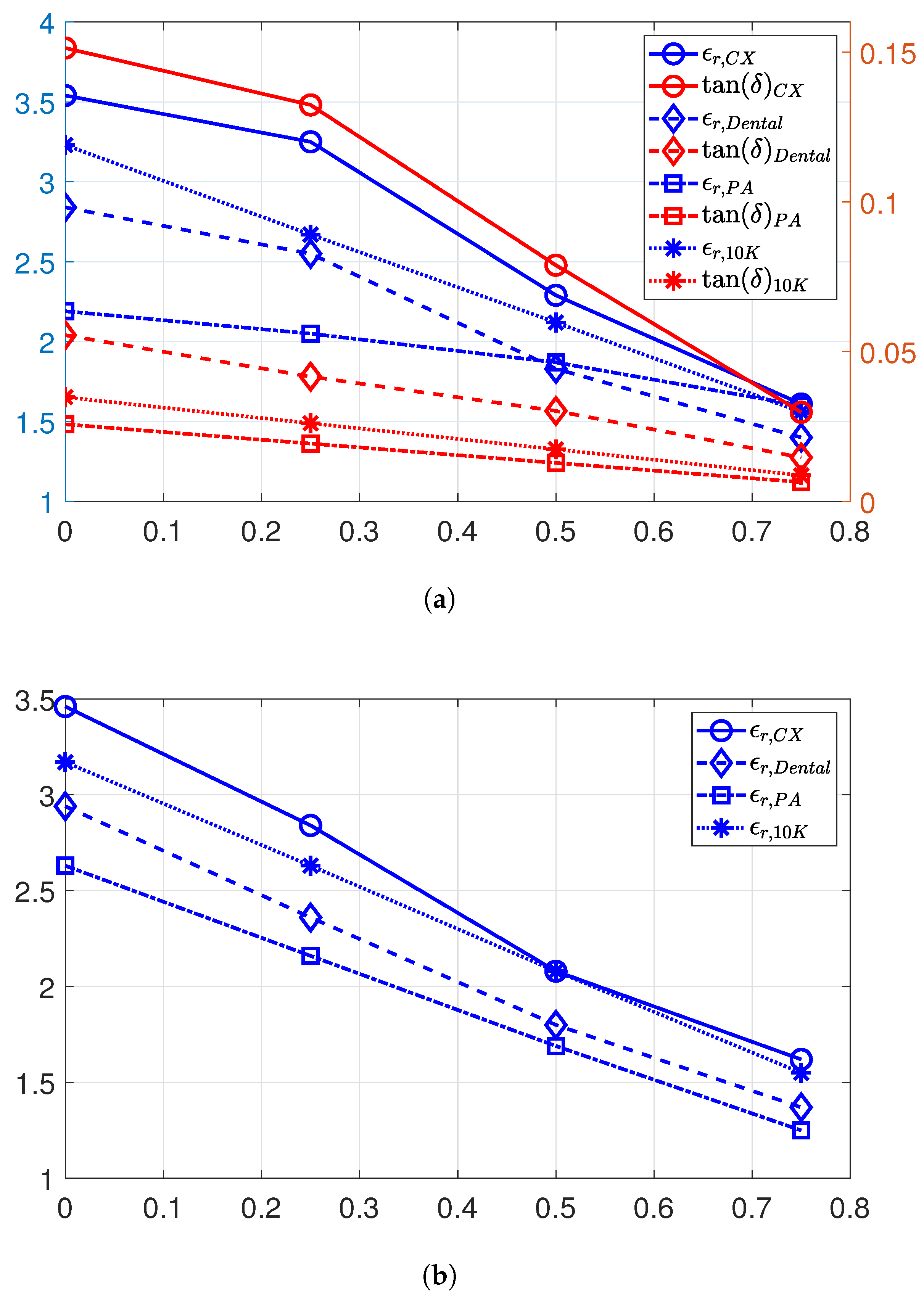
Figure 6.
Mechanical Design Dimensions of the X-Bend Antenna Assembly (a) Horn elevation view. (b). Horn plan view (c). Supports profile view. (d) Plan view of the X-Bend Lens.
Figure 6.
Mechanical Design Dimensions of the X-Bend Antenna Assembly (a) Horn elevation view. (b). Horn plan view (c). Supports profile view. (d) Plan view of the X-Bend Lens.
Figure 7.
Farfield simulated directivity of the lenses at 10 GHz, , in comparison with the horn antenna.
Figure 7.
Farfield simulated directivity of the lenses at 10 GHz, , in comparison with the horn antenna.
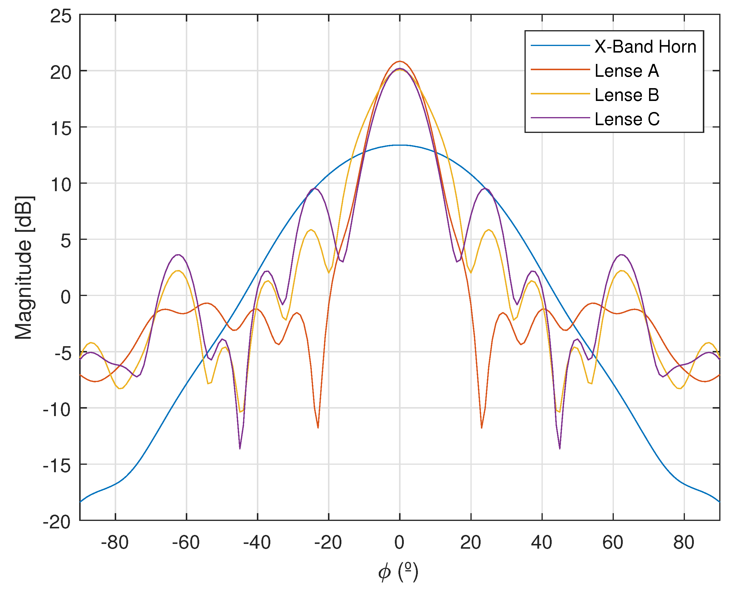
Figure 8.
Manufactured Prototypes (a). Feeding horn antenna, material Rigid 10K resin, technology VPP, sandblasted (b). Horn antenna after Ni+Cu autocatalytic coating. (c) X-Band lens assembly: feeding horn, supports and lens.
Figure 8.
Manufactured Prototypes (a). Feeding horn antenna, material Rigid 10K resin, technology VPP, sandblasted (b). Horn antenna after Ni+Cu autocatalytic coating. (c) X-Band lens assembly: feeding horn, supports and lens.
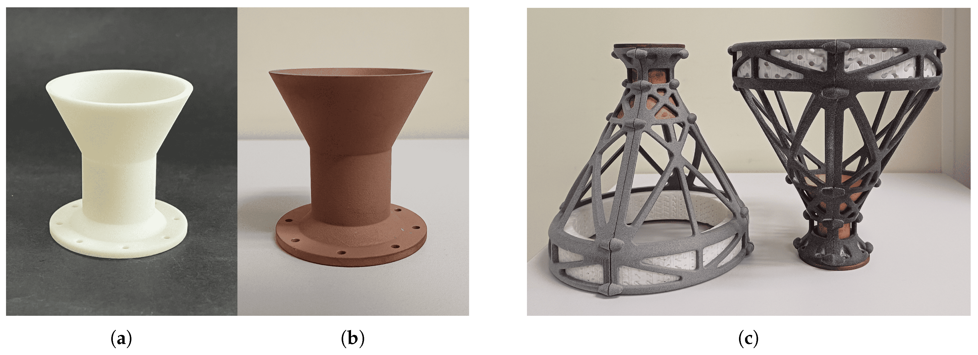
Figure 9.
X-Band GRIN Lenses: (a) Lens A, material Composite X resin, technology VPP, (b) Lens B, material Dental resin, technology VPP, (c) Lens C, material Rigid 10K resin, technology VPP.
Figure 9.
X-Band GRIN Lenses: (a) Lens A, material Composite X resin, technology VPP, (b) Lens B, material Dental resin, technology VPP, (c) Lens C, material Rigid 10K resin, technology VPP.
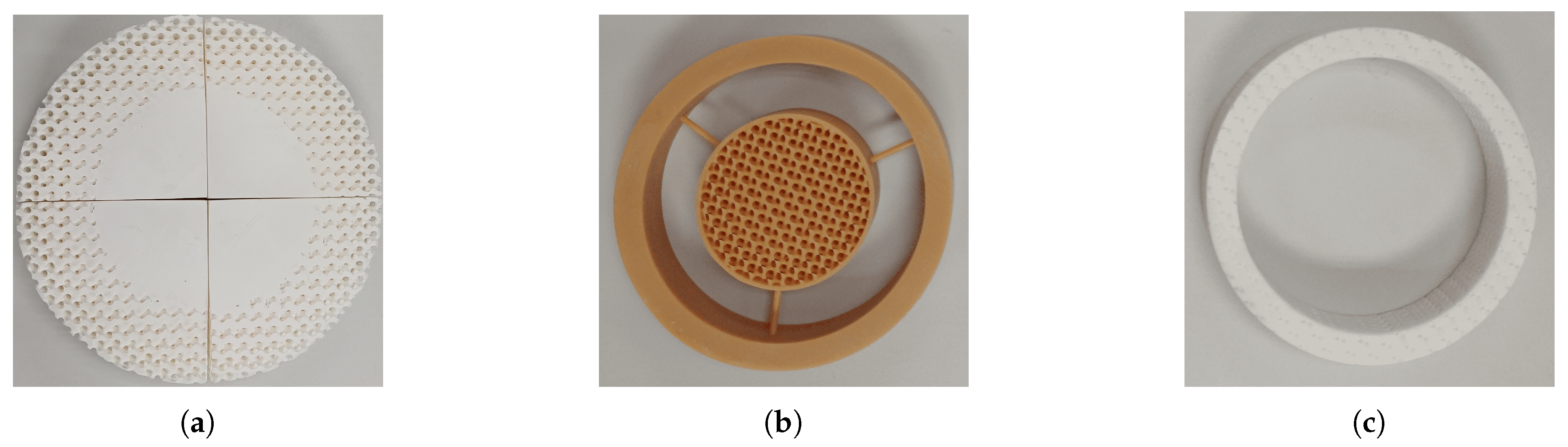
Figure 10.
X-Band Antenna Assembly Measurements in laboratory anechoic chamber.

Figure 11.
Farfield measured directivity of the lenses at 10 GHz,
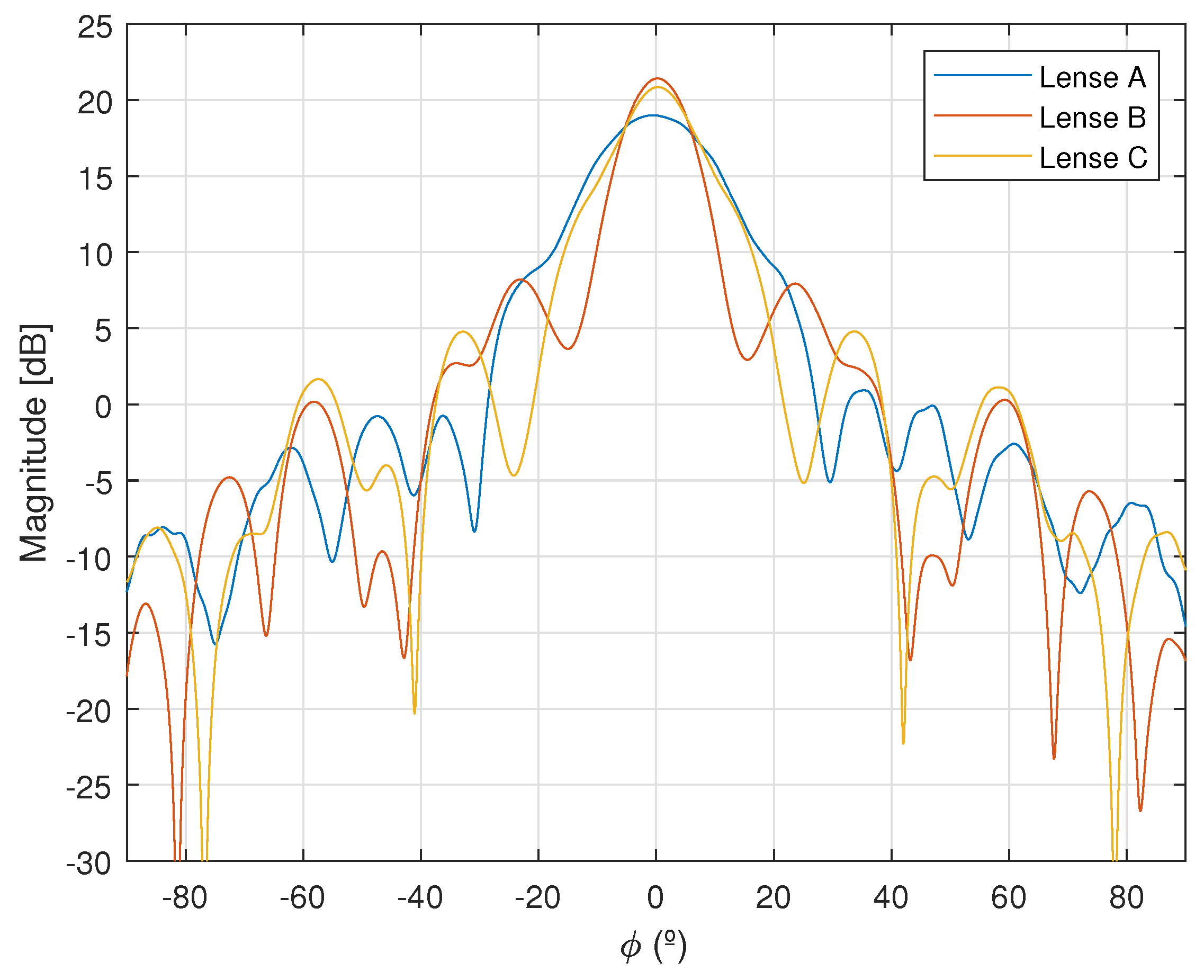

Table 1.
Solid Sample Measurements.
| f = 2.45 GHz | f = 6.25 GHz | f = 24.5 GHz | |||||
| Resin | Dens. | ||||||
| CX | 1.52 | 3.54 | 0.15131 | 3.67 | 0.1942 | 3.46 | 0.033 |
| Dental | 1.30 | 2.84 | 0.05549 | 2.83 | 0.05006 | 2.94 | 0.06 |
| Tough | 1.11 | 2.89 | 0.03341 | 2.95 | 0.03745 | - | - |
| Ultrasint PP | 0.89 | - | - | 2.19 | 0.03584 | 2.19 | - |
| Rigid 10K | 1.63 | 3.23 | 0.03479 | 3.32 | 0,03489 | 3.17 | 0.02 |
| PA11 | 1.01 | 2.38 | 0,02357 | - | - | - | - |
Table 2.
Variable Density Sample Measurements.
| f = 2.45 GHz | f = 24.5 GHz | |||||
| Resin | Porosity. | Dens. | ||||
| CX | 0.25 | 1.14 | 3.25 | 0.13232 | 2.87 | - |
| CX | 0.5 | 0.76 | 2.29 | 0.07884 | 2.08 | - |
| CX | 0.75 | 0.38 | 1.62 | 0.02978 | 1.61 | - |
| Dental | 0.25 | 0.98 | 2.55 | 0.05614 | 2.36 | - |
| Dental | 0.5 | 0.65 | 1.83 | 0.03021 | 1.80 | - |
| Dental | 0.75 | 0.33 | 1.40 | 0.01467 | 1.37 | - |
| PA11 | 0.25 | 0.76 | 2.05 | 0.02833 | 2.08 | - |
| PA11 | 0.5 | 0.61 | 1.87 | 0.02767 | 1.76 | - |
| PA11 | 0.75 | 0.51 | 1.6 | 0.01763 | 1.35 | - |
| Rigid 10K | 0.25 | 1.22 | 2.67 | 0.02609 | 2.63 | - |
| Rigid 10K | 0.5 | 0.82 | 2.12 | 0.01740 | 2.08 | - |
| Rigid 10K | 0.75 | 0.41 | 1.56 | 0.00870 | 1.54 | - |
Table 3.
Parameters of Mechanical Design of the X-Bend Antenna Assembly.
| Parameter | Dimmension (mm) | Parameter | Dimmension (mm) |
| C1 | 29.74 | C2 | 7.07 |
| D1 | 56 | D2 | 23.40 |
| D3 | 48 | D4 | 56 |
| D5 | 2.8 | D | 160 |
| L1 | 33 | L2 | 25 |
| L3 | 80 | H | 25 |
| T | 2 | f | 131.6 |
| R | 12.5 | g | 25 |
Table 4.
Values of of the GRIN lens models
| A | 1.70 | 2.25 | 2.96 | 3.54 | 3.54 | 3.54 | 3.54 | 3.54 | 2.96 | 2.25 | 1.71 |
| B | 2.84 | 1 | 1 | 1.37 | 1.49 | 1.59 | 1.49 | 1.37 | 1 | 1 | 2.84 |
| C | 2.75 | 1 | 1 | 1 | 1 | 1 | 1 | 1 | 1 | 1 | 2.75 |
Table 5.
Weight of the X-Bend Antenna Assembly.
| Device: | Conical Horn | Supports | Lense A | Lense B | Lense C |
| Weight (g): | 22 | 96 | 376 | 207 | 163 |
Table 6.
Comparison of different realizations of 3D printed perforated dielectric GRIN lens antennas.
Table 6.
Comparison of different realizations of 3D printed perforated dielectric GRIN lens antennas.
| Ref. | Freq. [GHz] | Lens Type | Tech. | Mat. | Feed Type | Diameter / Thickness (F+T) mm. | Dir. (Sim. / Meas.) | Ap. eff. (Sim. / Meas.) |
| lens A | 10 | Flat heterogenous | SLA | Composite X Resin | Circular Waveguide | 160 / 25 | 21 / 19.5 | 49.1 % / 32.17 % |
| lens B | 10 | Airy disk | SLA | Dental Resin | Circular Waveguide | 160 / 25 | 20 / 22.1 | 41.22 % / 55.80 % |
| lens C | 10 | Ring | SLA | Rigid 10K Resin | Circular Waveguide | 160 / 25 | 20 / 22 | 42.37 % / 49.21 % |
| [27] | 12, 15, 18 | Flat finite Focal GRIN lens | FFF | PLA | Circular Waveguide | 120 / 18.5 | 18 at 12 GHz / 21.4 at 15 GHz / 24 at 18 GHz 3 | 18% at 12 GHz / 33% at 15 GHz / 41% at 18 GHz 3 |
| [28] | 12-22 | Zero Focal length GRIN Lens | FFF | PREPERM | Circular Waveguide | 150 / 90 | 22.6 / 22.9 | 38 % / 40 % |
| [29,30] | 34 | Flat Finite Focal Length GRIN Lens | FFF | PREPERM | Corrugated Circular OEWGs | 88 / 40.5 | 26.5 / 25.7 | 45 % / 37 % |
| [31] | 12-40 | Flat Finite Focal GRIN lens | FFF | PREPERM | Rectangular OEWGs | 120 / 18.5 | 15.1 at 12 GHz / 23.6 at 40 GHz 3 | 82 % 3 |
| [32] | 13.4 | 3D Shaped | FFF | PLA | Microstrip Patch | 180 / 223 | 26.3 / 25.1 | 66.7 % 2 |
| [33] | 15 | Rectangular | Mat. Jetting | Verowhite | Rectangular OEWGs | - / 59 | 21.3 / 19.1 | 30% 2 |
| [34] | 27 | Flat finite Focal GRIN lens | SLA | Resin | Microstrip Patch Antenna | 77 / 77 | 21.3 2 | 30% 2 |
| [35] | 33 | Fresnel Zone Lens | FFF | PREPERM | Rectangular OEWGs | 97.6 / 39.3 | 25.2 / 25.2 | - / 31.1 % |
1 There is no data on radiation efficiency, unity radiation efficiency is assumed. 2 Simulated data. 3 Measured data.
Disclaimer/Publisher’s Note: The statements, opinions and data contained in all publications are solely those of the individual author(s) and contributor(s) and not of MDPI and/or the editor(s). MDPI and/or the editor(s) disclaim responsibility for any injury to people or property resulting from any ideas, methods, instructions or products referred to in the content. |
© 2025 by the authors. Licensee MDPI, Basel, Switzerland. This article is an open access article distributed under the terms and conditions of the Creative Commons Attribution (CC BY) license (https://creativecommons.org/licenses/by/4.0/).
Copyright: This open access article is published under a Creative Commons CC BY 4.0 license, which permit the free download, distribution, and reuse, provided that the author and preprint are cited in any reuse.


