
Submitted:
12 May 2025
Posted:
13 May 2025
You are already at the latest version
Abstract
The elbow dislocation is the second most common human dislocation. In case of an injury, a fast and correct diagnosis is essential for a good convalescence. The diagnosis depends on the attending doctor's experience and is sometimes subjective. A technical device should assist the doctor during the first and follow-up examination to eliminate this subjectivity. This generates verifiable diagnostics within the usage of tomographic equipment. To reach this goal, this paper describes the first steps of developing this still-unknown system. Therefore, the knowledge of elbow examination was elaborated and transferred to technical requirements. Later, functional groups were built, and technical solutions were compiled. The best-rated solution yields the theoretical functional principle. To verify the principle and to gather further knowledge, prototypes are designed. The physical realization is made with Fused Deposition Modeling. Different actor principles are evaluated. Tests in computer tomography verified the possible use case. A functional test with a skeleton arm model in the technical solution proves its suitability. The requirements are confirmed and missing data are obtained. The application is registered for patent. Improvements are determined and a technical more sophisticated prototype is in progress. Cadaver arm tests are planned to validate the aspects medically.
Keywords:
elbow
; injury
; medicine
; computer tomography
; mechatronics
I. INTRODUCTION
The dislocation of an elbow is the second most significant factor of a dislocation in human medicine. Injuries will have a massive impact on the daily life of the patient. A fast and correct diagnosis is the basis of a successful convalescent and aims to recover the elbow’s complete flexibility after an injury. The actual diagnosis is based on a doctor’s manual examination techniques, mostly coupled with static tomographic imaging. Despite the doctors’ excellent knowledge, each examination includes substantial subjective factors involving the medical personnel. To reduce this subjective impact, a new technical device is designed to support the doctor’s first and follow-up examination of the elbow joint. This device will generate objective data and enables the usage of more-dimensional tomographic imaging tools to gather a more excellent overview of the injured elbow joint. With the reproducible procedures of the new device, the knowledge of the sensor data, the patient information and an expressive more-dimensional imaging the doctor gets further and comparable values which are forming the basis of the diagnostic. The priority of imaging will be computer tomography (CT). The obtained information will help the doctor to get a greater overview of the severity of the injury and generate a more precise and individual convalescent for the best recovery of the elbow joint.
Tools for elbow injuries still exist, but their application area is the patient’s rehabilitation based on a preceding diagnostic. One standard device for daily life rehabilitation are orthosis, like Medi Epico Rom. This is used for early arm movement, which has the ability to stabilize and limit the motion. The device settings are based on the prevented diagnostic [1].
An advanced device with sensors is the Arm Tutor from SVG-Reha-Systeme GmbH & Co. KG. Its use case is the functional training of typical life motions based on therapy models. Sensors measure the range of motion of the elbow joint and the shoulder during movements in Extension/Flexion, Abduction/Adduction, and rotation. The results can be viewed in real time allowing information about the healing process [2].
Further, active-powered systems with continuous passive motion therapy (CPM) assist in the healing of passive motion components and get a higher joint movement in less rehabilitation time. An example is the ARTROMOT-E2 from ORMED GmbH at the Enovis Group. The device’s movements are programmed by medical personnel and rely on the injury diagnosis [3].
A stationary device using the robots’ technique is the ARMin V from ETH Zürich. This software-sensor combination allows for automatic support adaption according to the patient’s needs. This should increase therapy session outcomes and generate new therapy concepts [4].
MyoPro from MYOMO Inc. is an exoskeleton with active motion support. This System is for patients who can’t move their arm and hand. The aim is to support and recover a paralyzed or weak upper extremity. The system recognizes the muscle signals and steers the selected motors. The producer describes the system as power steering for the arm [5].
These devices might seem plausible for the new use case, but they can’t serve the requirements in the diagnostic area due to much more precise and complex correlations. Mostly the improved imaging results won’t be reached, or the flexibility of the device is lacking as far as the parameters of usage in diagnostic area is not focused. A simple translation to the new application of the existing systems is not possible. To our knowledge, no existing system is available in this area. This paper describes the first developments of a new technical concept invention for this type of application according to the registered patent [10].
II. METHODS
A. Requirements
First, medical requirements must be converted to a technical level to define a technical system. The system must be suitable for an initial medical examination and follow-up diagnosis. Based on the anatomical human model the complex system of the elbow joint is simplified to three basic functional groups. The relevant groups are the motion in extension/flexion, supination/pronation, and stress in the varus/valgus direction. The latest is to check out the ligaments of the elbow during forces. The others are for checking the joint during movement. The boundaries of each group are set on the known medical knowledge. Regarding the neutral zero method, extension and flexion are possible at 10° to 0° to 145°. Supination and pronation are declared within 90° to 0° to 90°. The boundaries are visualized in Figure 1.
The stress of varus valgus is reached by dislocating the forearm. With the expertise of the doctors, a maximal boundary from 100 mm is set for the stress in each direction. Each degree of freedom must be precisely controllable in single moves or as a combination of moves. This leads to a precise transmission with less backlash and a continuous or small step-by-step activation. In the diagnostic use case, no force from the device toward the elbow joint is allowed. This must be constructional decoupled. The system must be able to move the arm of a human in a force-free state, where the patient relaxes his muscles during examination. Only anatomic mass of the arm must be moved. In case of muscular tense, the system must stop or be guided by human to prevent further injuries. The mass of an arm is about 6% of the human weight and is distributed in 3% for the upper arm, 2% for the forearm, and 1% for the hand [7]. With a male’s weight estimated to be 90 kg, 2,7 kg will be the upper arm, 1,8 kg the forearm, and 0,9 kg the hand [8]. The focal point of the forearm and hand is in static situations at 90° flexion at about 130 mm distance towards the center of rotation [9]. Even so, the device must collect precise and verified data like forces, moments, angles, and distances in all directions. Later sensors, which interact with human reflexes and detect overuse, are possible. Also, interaction and easy handling with the system and its steering device are necessary. Further requirements are related to the usage of more dimensional CT systems. One of them is the limited operating space of the tube. Here, the sensitive center of the imaging device must be used to get the best results. The system has to be steered outside the dangerous radiation area of the CT and, more importantly, the artifact-free imaging of the elbow joint during operation with the device. Generally, metallic materials should be avoided. For medical use, systems must first observe cadaver tests to get a medical license. The new system must meet these requirements due to already planned tests. But should not preclude using humans.
B. Functional Concept
In the following figures, the human arm is implied in grey, the construction is blue, and the actor elements in black or green. In each functional group a small excerpt of possible operating principles will be listed and rated.
For the group in extension and flexion, rope-based actors as in Figure 2-1) are possible. The ropes are mounted on a supporting structure parallel to the arm. Approving this system is an easy construction without metal. Negatively, the actor’s greater force due to the system’s friction losses. Also opposing are the ropes stretching a mesh over the operation area and the double joint created by the supporting structure. The latest causes undesirable force effects on the injured elbow in case of mismatch and favors further damage even at best positioning. This could occur even during moving the arm.
Similar to the rope system, a linear cylinder mounted in the action ratio of the flexion (Figure 2-2)) or behind the upper arm (Figure 2-3)) is possible. Within an associated parallel support structure is necessary. Approving the in-action ratio mounted cylinder is a lower force and the possibility, but not recommended, of using the system without a supporting structure. In this case, only the elbow joint leads the movement and has the precondition that the injury allows a non-supported examination. Otherwise, the supporting structure assists the joint with the disadvantage of getting forces by misaligning the joints. Also damaging is the liner actor’s position in the arm’s action area. The actor needs to reach a small basic housing for flexion and, simultaneously, an extensive length to cover the whole extension range. The supporting structure for the articulation from the backside of the upper arm mounted linear actor is necessary. Unavoidably, a double joint emerges with opposing forces on the injured elbow. Positives are not contradictory requirements for the actor, which allows the use of technically established linear actors.
A different approach is in Figure 2-4) a fixed plate with grooves in different radii. The upper arm is fixed on a defined position at the plate. The wrist is fixed on a rope or belt-powered sled, guided in one of the radial tracks. The track depends on the size of the arm. Vivacious is the plate and arm’s fixed examination position during imaging. This allows for better quality and produces comparable scientific examination results. A negative point is the fixed justification of the device, which defines more significant steps. This favors the case of a mismatch in the center due to the individuality of each patient and generates forces on the elbow joint. The negative aspects of the elbow joint are similar, as already mentioned.
A similar solution that improves the adverse facts is a fixed plate with just one radius and a in small steps settable sled in the radial direction. This can be seen in Figure 2-5). The positive side is the finer adjustment, which allows for an easier match of both pivot points. This generates lower forces on the elbow joint. Negative is still the force that can’t be eliminated in each situation. In both mentioned plate solutions, the vast space requirements are adverse in comparison to the low available space of the CT tube.
In Figure 2-6), a 2D robotic joint offers a space-saving approach for extension and flexion. This physically rebuilds the responsible part of the human elbow joint for this motion. The forearm and the upper arm will be tightly fixed on their counterparts of the constructional elements from the robotic joint. This is necessary for the precise motion of the system. The difficulty is fitting both joints together. Each dislocation leads to undesirable forces. The negative impacts are similar to the mentioned ones before.
A solution without forces on the elbow joint is a plate with a sliding surface and a free sled. This system is outlined in Figure 2-7). The upper arm is fixed on the plate while the forearm is attached to the sled and will be activated by a guided rope actor. The precondition is that the elbow injury allows unsupported arm movement, which restricts the possibility of examining most elbow injuries. The negative is also the considerable space requirements of the system and the complex powertrain.
The reflection of the mentioned ideas leads to Figure 2-8), which shows a plate with a fixed radial groove and an inside-driven sled. Ropes or a timing belt actuate the sled, which includes a sliding guide for the radial degree of freedom. This prevents all forces on the joint at every position and allows accurate positioning each time. The negative is the more significant space requirements of the system compared to other solutions.
In supination and pronation, the base of the motion is a two-component slewing ring. Both tubes are concentric and slide radially together. To fix the axial displacement, a minor groove splits the external ring. In this groove, the counterpart of the inner ring is sliding. In the inner tube, a construction is designed where the hand can be fixed. To gain motion, the inner ring will be actuated.
One possible solution is a rope-based actor, as Figure 3-1) shows. Therefore, two counterpart working ropes are fixed on two selected points on the inner ring, allowing the motion to be generated as a pro contra actor. This is sketched in Figure 3-2). Each rope can be pulled/pushed by a winch, a reversing gear, or a linear actor connected towards the rope. The winch system is positive if you have long distances between the actor and actress and if higher force transmissions are needed. Negative are the double system components and their larger construction space. A rope system actuated by linear actors is similar, as sketched in Figure 3-3). These positively affect installing massive force transmission with short ropes near the ring actor. Negatively, this technique needs, in addition to the respected angle of rotation, a long actor range. This exceeds the limits of available space. Figure 3-4) and 5) show a more petite but less intense actor with a reversing gear powered by a rotatory motor. This can be placed near the ring actor. The system needs a muscular rope tension to transmit the necessary forces, which are still less than the previously mentioned actuation principles. Due to the intense tension, higher friction losses will be caused.
A linear actor directly mounted on the slewing ring (Figure 3-6)) produces a positive direct force transmission without high friction losses. The negative side of this actuation is the restricted rotation angle. At a specific point, the actor must drive through the center of the inner ring, where the arm is fixed in this use case. Further, the exact positioning is non-constant despite the chosen powering concept.
The combination of the slewing ring and a linear actor (Figure 3-7)) shows a part-turn actor. The advantage is that it integrates the actor in the construction, and a compact actuation system can be reached. Hydraulic or pressured air might be suitable due to its easy nonmetallic construction. In this case, positioning at exact angles is difficult to achieve, requires more steering equipment, or is complex. With electrical actors, the metallic components could disturb the imaging process.
Another solution is a cogwheel on the groove of the inner ring powered with a suitable rotatory motor. This is shown in Figure 3-8). Positive is the easy and precise control of the system with known techniques. Further, constructional unlimited angle can be set. The negative is the parallel positioning of the motor due to the system’s space requirements. Figure 3-9) is a more space-saving solution with its motor-powered worm shaft. Another positive aspect is the vertical positioning of the motor towards the ring actor and its huge force transmission. Smaller motors can be used and mounted more space-savingly than the cogwheel solution. The negative is the lower speed of the slewing ring due to the worm shaft actor.
In the case of varus-valgus stress, the wrist had to be deflected in the determined range to test the ribbons of the elbow joint. This can be reached by a rope-based actor like in Figure 4-1) or a dual linear actor, as Figure 4-2) shows. Both need to be fixed on an enclosing construction parallel to the forearm. The structure has to be mounted on the solution of the extension/flexion system to take up the deflection counterforce and stabilize the upper arm and elbow joint. The rope system powered by a winch can be easily placed outside the arm. Negative is the more significant space requirements and the higher friction losses. The dual linear actor can be mounted on the construction on top of the wrist. This enables a direct and easy force transmission. Otherwise, the linear actor causes a higher weight in the arm, which is negative for examining injured joints.
Another empowering of the stress is shown in Figure 4-3) using a bellow system engaged on the bottom of the wrist. The initial point of the system is in the middle of the bellow range. The positive stress can be reached by pumping up the elbow, and the negative one can be omitted by using the arm’s weight. Positive is the adjustable hardness of the system due to its pressure-controlled motion. However, the resilient effect can also be harmful, especially when reaching exact positions and force applications. Further, a defined system control is only possible in positive direction. In the negative direction, the system motion is based on the forearm parameters, which are individual to each patient. With this technique, especially in the negative direction, a defined examination with comparable solutions to other patients is impossible.
A better solution in Figure 4-4) eliminates the mentioned negative aspects based on the principle of a scissor car jack. In this solution, the huge lengths needed to reach the demanded height for applying the stress are adverse. The reason is the restricted space requirements for imaging progress in a CT. To reduce the length of the system, the principle can be stacked to create a scissor lift system, sketched in Figure 4-5). There, higher heights with shorter bars are reached. This positive side is caused by its more redirections resulting in higher force requirements towards the actor. The system’s reduced length compared with the stapled system architecture and its actuation principle occurs in a more significant space in the lower-end position compared to other solutions.
To get a small height in the lower position, a column lift powered by the linear actor (Figure 4-6)) or a belt system (Figure 4-7)) can fulfill the requirements. The necessary columns are mounted on the extension/flexion architecture. For a compact system, actors and guiding elements can be placed in the columns. The negative is the fixed height of the columns, which reducing the degree of freedom due to CT and imaging requirements.
A spindle drive in Figure 4-8) powers a similar actor system. Additional guiding elements are necessary for precise motion. Positively, these guiding elements can be independent and fit the surrounding conditions perfectly. Plausible therefore is a swallowtail guiding element with one degree of freedom. The construction of a spindle drive allows the transmission of high forces and a vertical mounting of the rotatory actors. Negative can be the fixed height of the spindle drive, which decreases the system’s flexibility in the CT.
The mentioned ideas are possible system solutions to reach the main motion for examining an elbow joint. All these system ideas can be powered differentially. Generally, electrical, pneumatic, and hydraulic systems could be possible. Each of them has individual advantages and disadvantages.
Due to its working principle with the fluidic medium, the hydraulic system can transmit greater force with a smaller construction size. Therefore, actors can be placed in areas with small assembly space, minimizing construction. The necessary steering equipment is a simple control unit, and all components can be quickly built from non-metallic materials. Negative is the essential circulation system of the fluid, which increases the system’s complexity. An exact positioning at desired positions still needs additional sensors and a regulation circuit. The accuracy is not even so good compared to other actuation systems. Even in stagnation, the system must be regulated, except the end positions.
The pneumatic system is like the hydraulic one but has the advantage of discharging the used air into the environment. Even so, all actors can be quickly built without metallic components and controlled with a simple control unit. Most of the time, pressured air is available in examination rooms of a hospital, so it hasn’t been generated. The necessary system components to generate pressured air are harmful if it doesn’t exist. Partly negative is the compressibility of air, which affects the exact positioning of the system. It also can be slightly positive if a damper system is needed. Also damaging is the necessary regulation, which each pneumatic actor system needs to reach exact positions even in stagnation except its final ones. The precision is also not so high as in comparable solutions.
At least electrical actors can be used. Positive is the variety of solutions and the exact and direct actuation that can be reached. No sensor elements are usually necessary if a designated system architecture is used. If sensors are needed, an easy attachment is possible. Further, each room has an electrical supply, and the motion control is more straightforward. In the case of linear systems, exact positioning is also likely in times of stagnation. Negatives are the metallic components of the systems, allowing only positioning in selected no-disturbing areas.
C. Prototyping and CT Test
The first technical scheme can be designed on the listed ideas and the different actuation strategies. As seen are the base of the actuation strategies already known systems which are new combined for this use case. This allows to use matured technique to get quickly a working system for the new area. Due to very old or lack of medical data in this area a profitable simulation of components is in this early state not effective. The functional concept fulfilment with a first technical realization is in focus which can be reached with technical knowhow. The summarized idea from a plate with a fixed radius groove and a sled with radial freedom due to a sliding area is selected in extension and flexion. Its positive parameters with precise and force free motion handling can neglect the larger space requirements which can be reduced by a constructional adaption to the CT form. In contrast to the other ideas this one is easy integrable with actuation combined with a robust and simple construction to avoid unnecessary complications with focus on the concept realization. The plate with the groove can be seen in Figure 5 number 3. The sled in the groove is shown in number 4, and the opposite sliding construction can be seen in number 5. In reflection on the requirements, the opposing side must be considered to get the most promising injury examination. The sled will be powered by a timing belt in the groove, controlled by a rotatory drive placed under the fixation of the upper arm (Figure 5 number 1). The timing belt allows a high force transmission in combination with the accurate positioning. On the counterpart of the sliding area, the varus-valgus part will be mounted. Therefore, a dual spindle drive with swallowtail guidance was selected (Figure 5 number 6). The choice fell due to the independent actuation and guidance architecture and the vertical positioning of the actor. The spindle drive allows a high transmission factor which can be adjusted during construction. The focus can be on the speed or on the force. In our case a higher force transmission is chosen to be able to use small, space-saving actors on the bottom. As actor rotatory drives are suitable. The competing ideas would be more complex in integration and actuation as well as less flexible and require more construction site.
On top of the varus/valgus system, the supination pronation architecture can be mounted. As seen in Figure 5 number 7, a slewing ring powered by a worm shaft is most suitable. Reason is the space-saving vertical drive position and the more significant force transmission with still acceptable speed. Despite the other ideas the non-existent angle limit allows a flexible adjustment during examinations. Figure 3-8) can afford this as well but is worse in space requirement and force transmission. To avoid further injuries, the limit must be set sensible by software. As an actor, a rotatory drive is suitable. The actuation of rotatory drives is chosen after the first basically tests with the selected techniques.
With this theoretical model, prototypes are built to verify the known parameters and generate further unknown information. For fast prototyping Fused Deposition Modeling (FDM) is used with PLA as material. The infill density is set to an average value of about 30%, which is enough to test the suitability of the whole system due to its requirements as a functional demonstrator. On account of printing all components with PLA, the interaction of the construction elements will be given but is not rated as a priority because of unoptimized material contact areas. The friction losses will be greater than using harmonized materials.
The first prototype is built to functionalize and check out visually the fundamental requirements. Actors are not included in this version. The construction of the prototype is based on general calculations and constructional know-how. An extensive simulation does not occur due to missing parameters for an expressive solution. The operating space of the complete device in a CT tube is possible but allows less justification. This is proven by the human skeleton arm, whose elbow joint must be in the center of the CT tube to reach the best imaging. A static imaging process of the prototype with a mounted skeleton arm, similar to Figure 6 showed a perfect fit between theoretical and practical knowledge. Small deviations from the center are not affecting the quality of static imaging. Further, various mounting strategies for metal-affected electrical components and their imaging impact are tested. Due to the literature, it’s known that metallic material will cause imaging interferences. In this case, it depends on the interesting imaging point and the position of metal rated towards this point. Within the new reconstruction software of the CT and the function of 3D imaging, the effects of metallic components are partly unknown and are specific to each manufacturer. For our tests Siemens NAEOTOM Alpha CT is used. As an outcome, metallic devices are not disturbing and have minor impacts on the regions of interest for the examination if the direct area of the elbow joint is free from it. In this software, all imaging effects are limited to areas where metallic components were placed. However, the best thing is still to prevent metallic components, but a selected usage is possible.
Further, constructional deviations are detected for refinement. Here, the chosen fittings in gliding parts and areas with functions must be improved to achieve higher accuracy and stability. The general calculations must be adapted, especially in the extension/flexion groove and the gliding area for varus-/valgus stress. Not considered parameters, like disassemble problems during testing with manual powering by hand, are figured out.
With these data a second prototype equipped with an Arduino Mega 2560 Rev3 as the central controller is built. The focus of this prototype is the first stand-alone system of the fundamental functional principle. To actuate the system, stepper motors as rotatory actors with motor drivers are implemented. Their elected usage base on the knowledge of imaging impacts from the previous prototype. Electric motors are the easiest way to get a rotatory actuation because of its simple installation and operation. Fundamental power distribution is in each examination room available and easy to distribute for any device, compared to compressed air and hydraulics. In extension/flexion a 40 Ncm stepper motor is chosen for actuating the sledge with timing belt resulting from the weight of the arm. In supination/pronation a 16 Ncm motor actuates the worm shaft of the slewing ring and for varus- valgus stress two 16 Ncm stepper motors are used. For each degree of freedom selected optical sensor devices as reference points are installed. In this use case, the possible level of sensor implementation is much higher than respected, but for a first automatic motion they are enough. In following devices, more sensors based on the requirements will be attached. A small ten double-sided button board is installed to interact with the prototype. Fundamental motor control in each direction as far as first automatic programs can be triggered with it. The software on the Arduino board is written to test the actors and the system. At least an example of a possible examination process is implemented. Additionally, a joint stabilization, as seen in Figure 5 number 2, is mounted to improve the imaging process.
The function test of the actors themselves and the whole system test resulted in positive aspects. The software, motors, sensors and the steering components are working together and are suitable for the functional demonstrator. All actors and sensor components work as expected, but some devices had to be harmonized to improve the system.
The following tests on this prototype using a dynamic 4D CT imaging to verify the intended application area. Here, the prototype processed an example examination strategy during a 4D CT scan. As proven with the first prototype, the placed actors and their connections did not impact the imaging. Further investigations with additional metallic material showed that the CT software also performs well during dynamic imaging. Anyway, the limits can be easily exceeded in case of obsessive usage near the significant areas of the elbow joint. In this case, artefacts will obscure the important sectors.
For verification, a dynamic 4D CT scan with a mounted skeleton arm model is conducted. This serves as a precursor to the cadaver arm tests and is used to confirm practically the functional principle. Figure 6 shows the setup. The implemented possible examination process is used for the imaging. Multiple imaging cycles were performed.
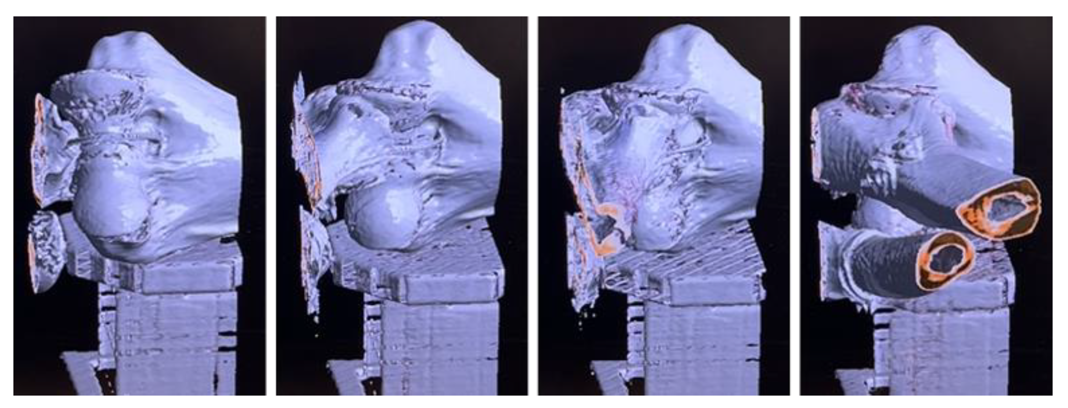
In Figure 7 excerpts of the resulting 4D model of the skeleton arm can be seen. The evaluation was carried out visually due a lack of quantifiable observation points. The results are repeatable. During the measurements slight displacements from the center of the CT tube do not affect the imaging. The images are still gainful usable for diagnostics. This allows a more excellent space for the device’s forearm actor with no impact on the results. During all testing no imaging affects from the system are visible in the significant areas. The results from previous test can be practically confirmed.
Regarding the successful imaging of the skeleton model, the fundamental examination strategy is achieved, and the system’s functionality is verified. The total advantage of this examination strategy can be estimated higher than expected.
Following doctors consider possible examination strategies for further improvements in the examination. In the actor part, the high-powered stepper motors are too small at some operating points to apply the required force during the arm examination. Huge impact has the high friction losses due to the 3D printing. Enabling higher power at the mounted motors is impossible. The increasing temperature would melt the PLA material. In constructional part changes to improve the stability and the system’s lifetime must be done. The enhancements are documented for a following more mature prototype. A use case extension of the tool towards chronic instabilities or elbow stiffness after a completed initial medication is possible to obtain a more objective indications for surgical treatment.
III. Conclusion
This paper set up a new technical device to improve the examination of elbow dislocations. The according patent is registered [10]. For this idea, technical parameters were derived from medical requirements. Different technical solutions are elaborated and rated for the fundamental motion parameters in extension/flexion, supination/pronation, and varus/valgus stress. The most suitable combination was selected. The theoretical system was built in two prototypes to reach further unknown knowledge. This was made with Fused Deposition Modeling and PLA material for quick prototyping. The Prototype checked out the fundamental requirements and gained significant expertise and constructional improvements for further realization. A successful result from the prototype was using metallic components at selected points during the more dimensional CT imaging with Siemens NAEOTOM Alpha. This allows the selected usage of electrical components without interfering with the imaging. The second prototype is based on the knowledge and improvements from the first and is actuated with stepper motors, steering components, and most essential sensors. With this system, the suitability of the technical invention for the use case in the first and follow-up examinations could be confirmed. The device successfully imaged a skeleton arm using a more dimensional imaging process. The possible improvements for the doctor of the new technique could be estimated. The development of the system is ongoing. A technically more mature prototype is in design and will be published. Further medical cadaver arm studies are planned with the new prototype. This study points out the medical importance of the new technique and will verify the system on a medical base. The results are expected shortly.
CONFLICTS OF INTEREST
The authors declare no conflicts of interest.
References
- medi GmbH & Co. KG. Product description of medi Epico Rom Orthosis. medi.de. https://www.medi.de/produkte/medi-epico-rom-s/ (accessed Jan.13, 2025).
- SVG-Reha-Systeme GmbH & Co. KG. Product description of ArmTutor. svg-rehasysteme.de. https://www.svg-rehasysteme.de/armtutor/ (accessed Jan.13, 2025).
- ORMED GmbH from Enovis Gruppe. Product description of ARTROMOT-E2. enovis-medtech.de. https://www.enovis-medtech.de/bewegungsschienen-fachkreise (accessed Jan.13, 2025).
- ETH Zürich. Product description of ARMin V. sms.hest.ethz.ch. https://sms.hest.ethz.ch/research/current-research-projects/arminrobot/armin-v.html (accessed Jan.12, 2025).
- MYOMO Europe GmbH. Product description of MyoPro. myomo.de. https://www.myomo.de/was-ist-eine-myopro/ (accessed Jan.12, 2025).
- S. Seitz, W. Rüther, „Funktionelle Anatomie und Biomechanik des Ellenbogens“, In: W. Rüther, B. Simmen, „AE-Manual der Endoprothetik“, Springer, Berlin, Heidelberg, 2013, p. 15, ISBN 978-3-642-34671-2.
- T. Koller, „Rehabilitation komplexer muskuloskelettaler Verletzungen: Kompendium für Physiotherapeuten und Ergotherapeuten,“ Springer Verlag GmbH, Berlin, Deutschland, 2022, p. 69, ISBN 978-3-662-63533-9.
- DESTATIS statistisches Bundesamt. Köpermaße nach Altersgruppen und Geschlecht. Destatis.de. https://www.destatis.de/DE/Themen/Gesellschaft-Umwelt/Gesundheit/Gesundheitszustand-Relevantes-Verhalten/Tabellen/liste-koerpermasse.html (accessed Jan. 14, 2025).
- L. P. Müller, B. Hollinger, K. Burkhart, „Ellenbogen,“ Georg Thieme Verlag KG, Stuttgart, Deutschland, 2016, pp. 48-49, ISBN 978-3-13-174981-9.
- Prof. Dr.-Ing M. März, M. Meindl, F. Forster, Dr. med. L. Mangold, Dr. med. M. Simon, “Ellenbogenorthese,” registered for patent, German Patent, 14.02.2024.
Figure 1.
Visualization of elbow movement, on the basis of [6].
Figure 1.
Visualization of elbow movement, on the basis of [6].
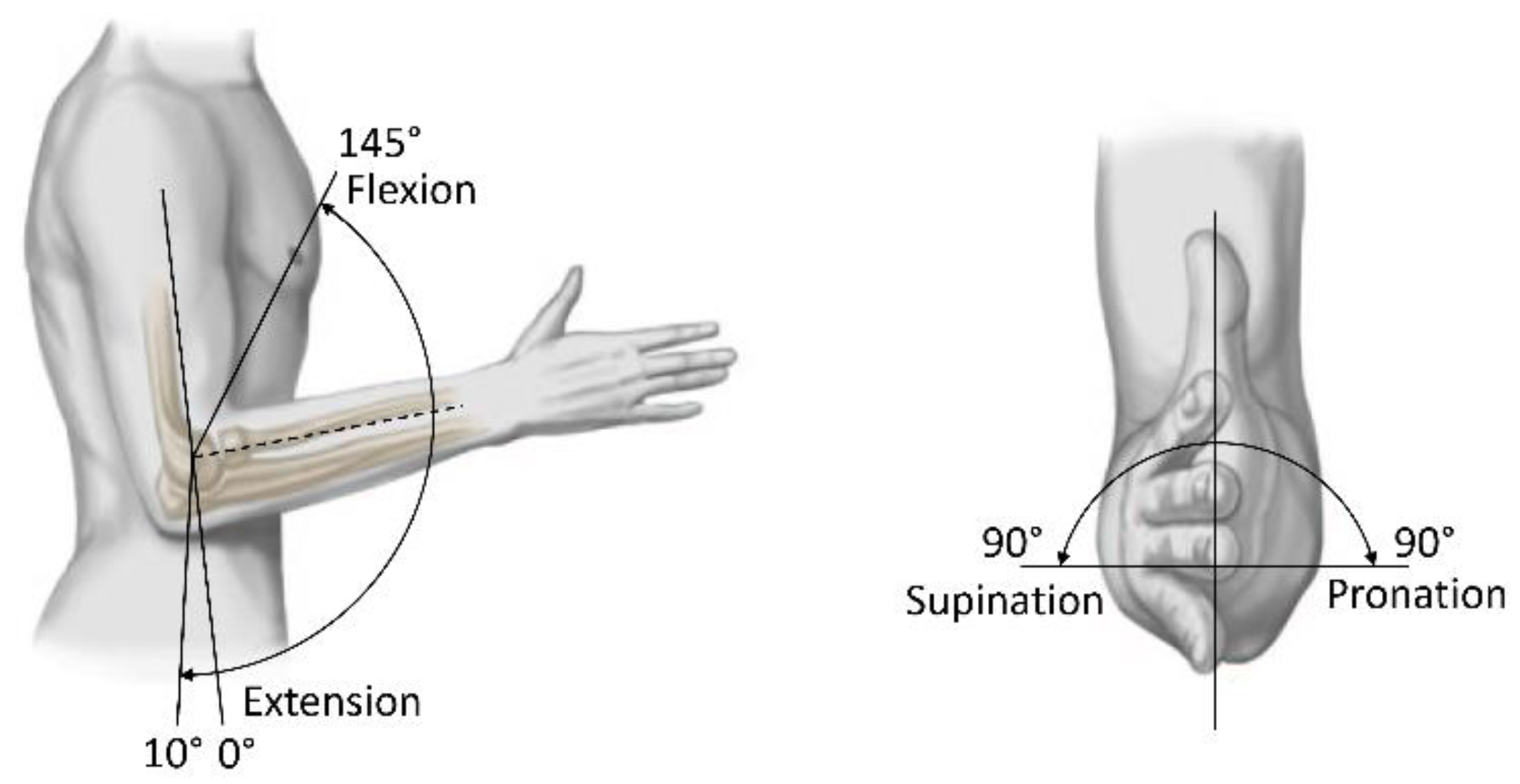
Figure 2.
Ideas for motion in Extension and Flexion.
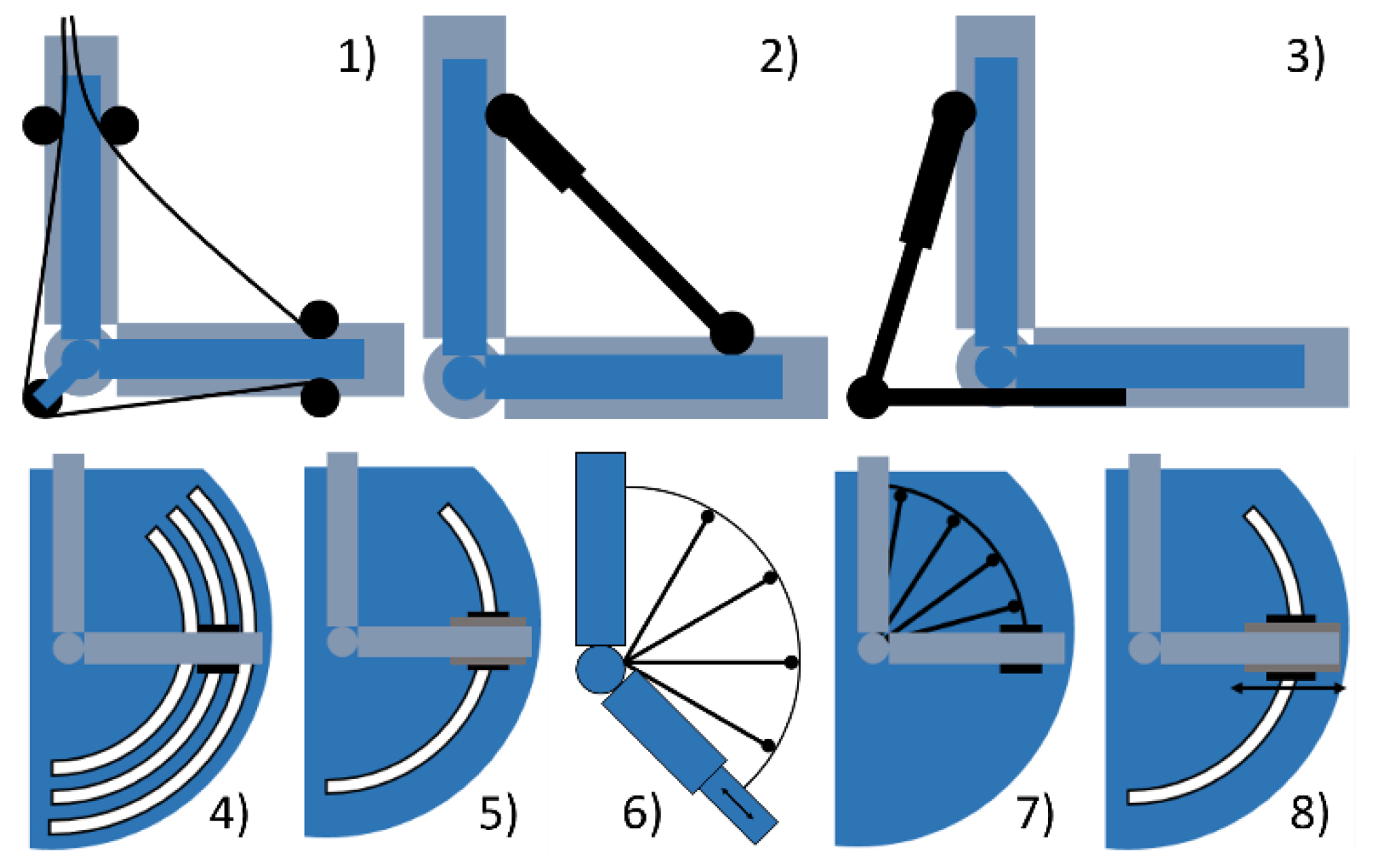
Figure 3.
Ideas for motion in Supination and Pronation.

Figure 4.
Ideas for applying Varus and Valgus stress.
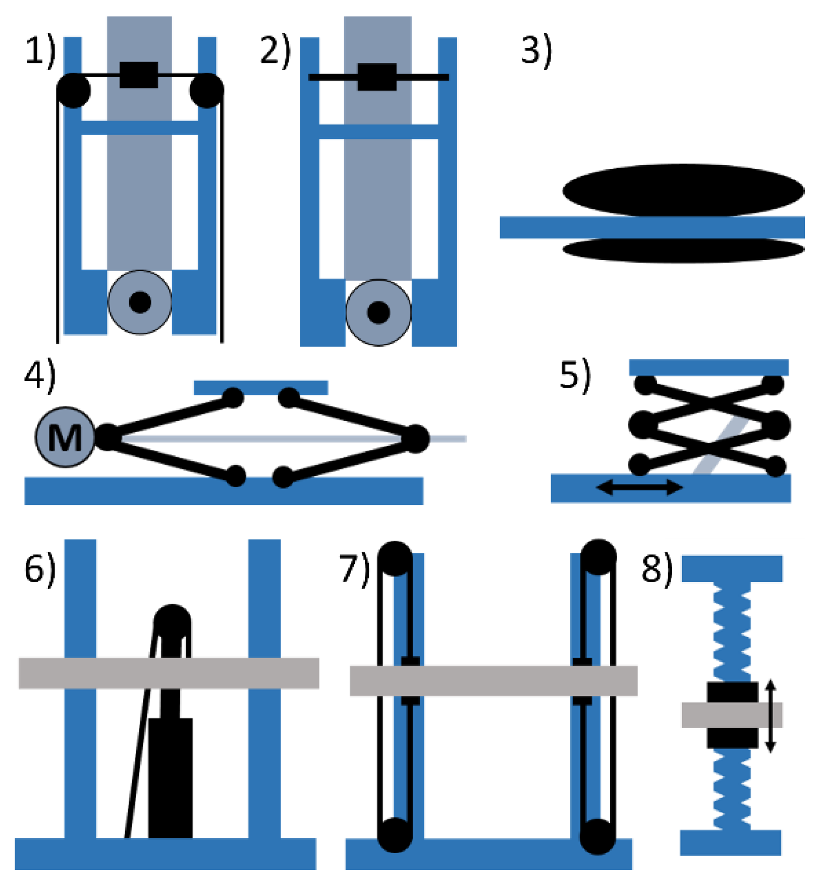
Figure 5.
Construction view of the second prototype.
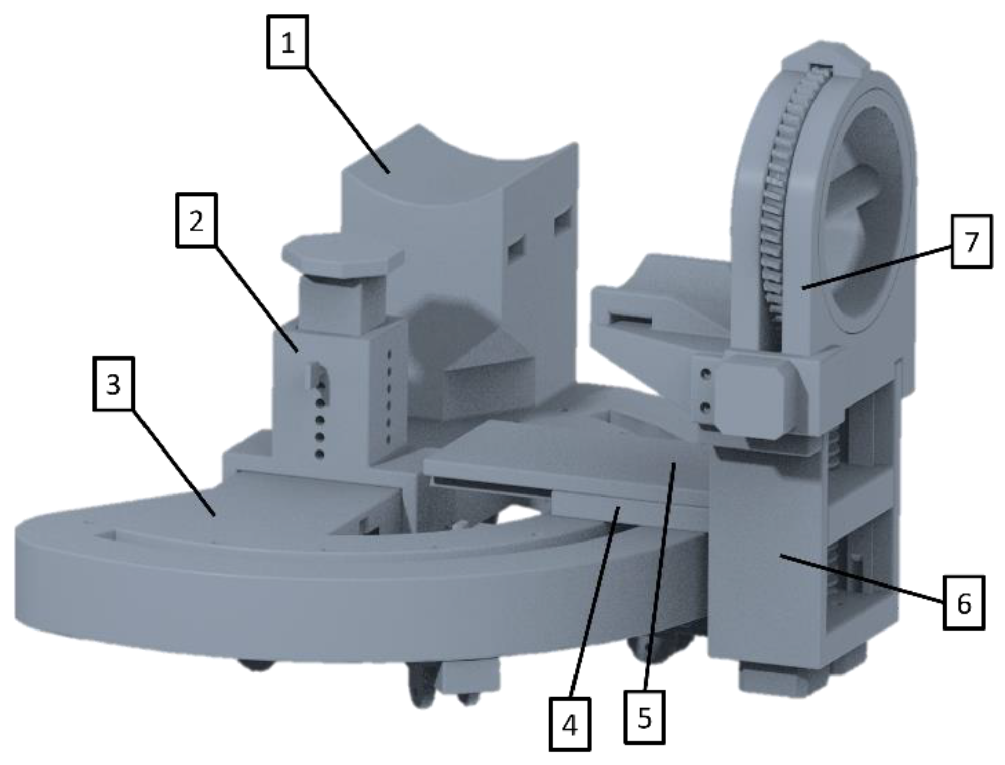
Figure 6.
Second prototype with skeleton arm model in CT tube.
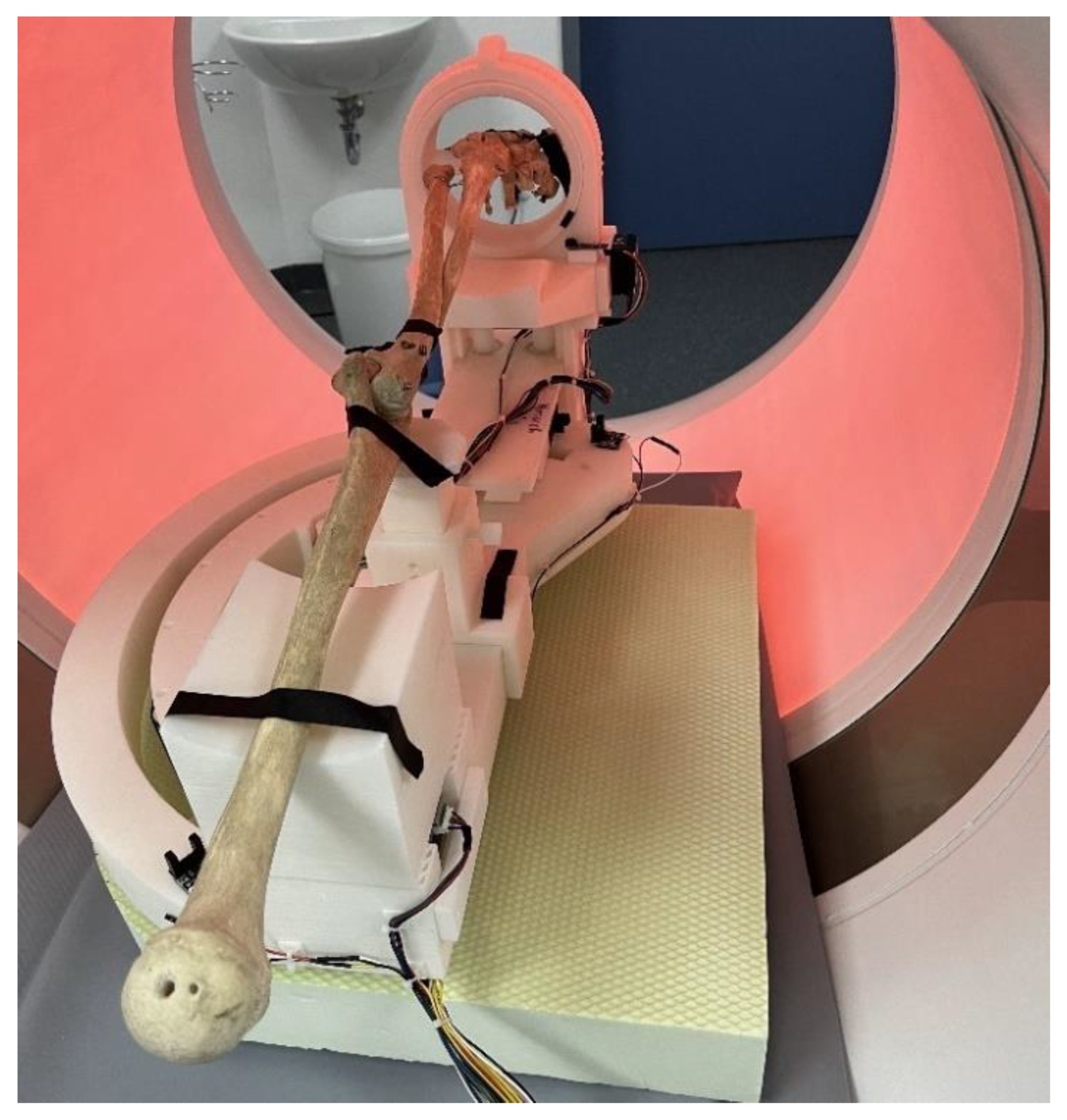
Figure 7.
Pictures of a skeleton arm in the 4D CT.
Disclaimer/Publisher’s Note: The statements, opinions and data contained in all publications are solely those of the individual author(s) and contributor(s) and not of MDPI and/or the editor(s). MDPI and/or the editor(s) disclaim responsibility for any injury to people or property resulting from any ideas, methods, instructions or products referred to in the content. |
© 2025 by the authors. Licensee MDPI, Basel, Switzerland. This article is an open access article distributed under the terms and conditions of the Creative Commons Attribution (CC BY) license (http://creativecommons.org/licenses/by/4.0/).
Copyright: This open access article is published under a Creative Commons CC BY 4.0 license, which permit the free download, distribution, and reuse, provided that the author and preprint are cited in any reuse.


