

Submitted:
10 May 2025
Posted:
12 May 2025
You are already at the latest version
Abstract
Micro gas turbines serve small scale generation where swift response and low emissions are highly valued, and they are commonly fuelled by natural gas. True to their ‘micro’ designation, their size is indeed compact; however, a noteworthy portion of the enclosure is devoted to power electronics components. This article considers whether these components can be made even smaller by substituting their conventional silicon switches with switches fashioned from silicon carbide. The wider band gap of silicon carbide permits stronger electric fields and reliable operation at higher temperatures, which together promise lower switching losses, less heat, and simpler cooling arrangements. The study rests on a simple volumetric model. Two data sets feed the model. First come the manufacturer specifications for a pair of converter modules (one silicon, the other silicon carbide) with identical operation ratings. Second are the operating data and dimensions of a commercial 100 kW micro gas turbine. The model splits the converter into two parts: the semiconductor package and its cooling hardware. It then applies scaling factors that capture the higher density of silicon carbide and its lower switching losses. Lower switching losses reduce generated heat, so heat sinks, fans, or coolant channels can be slimmer. Together these effects shrink the cooling section and, therefore, the entire converter. Findings show that a micro gas turbine inverter built with silicon carbide occupies about one fifth less space and delivers more than a quarter higher power density than its silicon counterpart.
Keywords:
Micro Gas Turbines
; Silicon Carbide
; Power Electronics
; Power Density
; Size
1. Introduction
For more than two decades, micro gas turbines (MGTs) have shown notable advantages over other small-scale power generation technologies, such as reciprocating engines. These advantages include fewer moving parts, lower noise and vibrations, reduced emissions, making MGTs attractive for distributed generation [1]. One of the most commonly employed fuels in MGTs is natural gas, owing to its affordability, comparatively low carbon intensity, and availability. In addition, MGTs have low thermal and mechanical inertia, enabling rapid start-up times [2] and swift transitions between partial and full load [3]. Despite these attributes, challenges regarding system volume and power density persist, since the power electronics components occupy a substantial portion of the total system. In MGT units, the power electronics account for over one-third of the whole unit [4]. Approaches that reduce the volume of these electrical subsystems could therefore substantially improve the overall power density.
Micro gas turbines comprise two principal subsystems, a mechanical and an electrical. As seen in Figure 1, the mechanical part includes a combustor and a compressor and turbine mounted on a single shaft, whereas the electrical subsystem is composed of a permanent magnet synchronous machine (PMSM) and power electronics modules, such as bidirectional power converters or a rectifier and an inverter. During operation, the compressor pressurises ambient air, which is then directed into a recuperator to recover heat from the exhaust gases. This heated air is then mixed with fuel (or is heated externally in externally fired MGTs) before combustion. The resulting high-temperature gas expands through the turbine, which drives both the compressor and the generator. Electricity is ultimately conditioned for delivery at the required voltage and frequency by the power electronics, thus enabling connection to the grid or local loads. A thorough description of power transmission and control in the electrical subsystem of micro gas turbines is presented in a previous work by the author of this article [5].
Since the PMSM in an MGT generally operates at high or variable speeds, its output frequency is usually unsuitable for direct grid connection. Power electronics converters, commonly a three-phase diode rectifier and a three-phase inverter, are employed to ensure a grid-compatible voltage and frequency [6]. These converters also provide essential control functions, including fast dynamic response and regulation of voltage and frequency.
Figure 1 also shows the schematic of a three-phase rectifier-inverter stage typically used in micro gas turbines. The current practice in micro gas turbine design relies on silicon insulated-gate bipolar transistors (IGBTs), although the industry is increasingly exploring wide-bandgap semiconductor devices to achieve superior performance, such as silicon carbide (SiC). Although micro gas turbine technology has progressed considerably, scope remains to improve power density and reduce the overall system footprint. Power electronics play a crucial role in determining the size of an MGT, and there is growing evidence that emerging semiconductor devices, particularly silicon carbide, can help minimise converter volume.
Figure 2 shows a photograph of a T100 Ansaldo Energia (AE) micro gas turbine unit, taken by the author of this article in 2022 at the University of Genova’s Savona Campus in Italy. The image illustrates that the power electronics subsystem occupies about one-third of the total volume [7]. Consequently, reducing this subsystem’s size would confer significant benefits in terms of power density.
MGT designs rely on silicon-based semiconductors, for instance, IGBTs and diodes, in their power converters [8]. While well established, these devices experience conduction and switching losses and require substantial cooling to maintain safe operating conditions, which contributes to larger converter modules. This added size and the associated thermal management overhead limit the overall power density. In contrast, wide bandgap materials, such as silicon carbide, allow higher switching frequencies, superior thermal performance, and reduced conduction and switching losses [9]. These properties make it possible to design smaller, lighter, and more efficient converter assemblies. Replacing silicon with silicon carbide in MGT power electronics thus constitutes a promising route to minimising converter volume and enhancing power density.
Recent research in other fields, other than micro gas turbines, further underscores the power-density benefits offered by silicon carbide-based semiconductor devices. For instance, Virginia Tech developed a 15 kW three-phase rectifier by replacing silicon semiconductors with silicon carbide ones for an aircraft application, increasing its specific power density from 2 kW/lb to 2.78 kW/lb [10], equating to approximately a 28% improvement. In another study, a converter that uses both silicon transistors and silicon carbide ones was investigated, and the silicon carbide-based converter showed a power density around 3% higher than its silicon-based counterpart [11]. These findings indicate that silicon carbide technologies can reduce converter size while enhancing power density in a range of power-conversion applications, thus motivating their adoption in MGTs.
Silicon carbide devices are characterised by higher critical electric fields, better thermal conductivity, and greater tolerance for high-temperature operation than conventional silicon devices [12,13]. As shown in Figure 3, the drift layer thickness of a 1200 V silicon carbide (in blue) metal-oxide-semiconductor field-effect transistor (MOSFET) is markedly smaller than that of its silicon (in yellow) counterpart [14]. Table 1 confirms these differences by demonstrating that silicon carbide can deliver a notably reduced footprint.
Furthermore, the capacity to withstand higher junction temperatures can mitigate or even eliminate bulky heat-sink requirements, thereby shrinking the unit size further. Experimental evaluations suggest that replacing silicon IGBTs with silicon carbide MOSFETs can boost converter power density by up to 28% or more in high-performance applications [10].
Despite their maturity, micro gas turbines employ silicon-based power devices [8]. However, the constraints of silicon regarding switching speed and thermal limits tend to increase the overall converter size. Meanwhile, substantial literature on the automotive, aerospace, and related sectors illustrates how silicon carbide implementations can effectively reduce converter volume and system losses. Nevertheless, the specific application of silicon carbide in MGT converters remains comparatively underexplored.
Given that power electronics typically account for a large proportion of an MGT’s total size, there is strong motivation to investigate silicon carbide-based solutions specifically tailored to micro gas turbines. This leads to the key research question: What is the potential for size reduction and power density enhancement if silicon-based power converters in micro gas turbines are replaced with silicon carbide-based converters? Addressing this question requires examining how the thermal and electrical advantages of silicon carbide may be leveraged to develop more compact, higher-power-density configurations for micro gas turbines. By focusing on these attributes, this research aims to illustrate how silicon carbide-based power electronics could reduce the unit size and/or increase the power density of MGTs.
2. Methodology
The AE T100 micro gas turbine was selected for this study due to its wide application in distributed power generation and cogeneration systems, making it a representative and relevant platform for evaluating improvements in inverter technology. The AE T100 has a clearly documented total volume, rated power output, and the inverter’s proportion within its overall size, providing an ideal baseline for assessing the impact of module technology advancements. Typically, the power electronics within micro gas turbines include a three-phase rectifier and a three-phase inverter. Together, these components usually account for approximately 30% of the total physical volume of the MGT. However, this study specifically focused only on the inverter system, which represents approximately half of the total power electronics volume which is 15% of the AE T100’s overall volume.
The inverter selected for this study is a three-phase system containing six IGBTs as shown in Figure 4. The specific IGBT modules chosen for comparison were the conventional silicon IGBT module (CM200DY-24TH) [15] and the silicon carbide hybrid IGBT module (CMH200DU-24NFH) [16], both manufactured by Mitsubishi Electric. These modules were carefully selected due to their comparable voltage and current ratings (1200 V, 200 A), enabling a fair and direct comparison between traditional silicon and advanced silicon carbide-based technologies. Additionally, detailed datasheets are available, providing comprehensive electrical, thermal, and mechanical characteristics essential for accurate and realistic modelling. Importantly, these selected modules align closely with the operational requirements of the AE T100 micro gas turbine, particularly in terms of voltage ratings, current handling capability, and switching frequency characteristics, ensuring compatibility and practical relevance of the study findings for real-world applications.
The AE T100 micro gas turbine is a small-scale power generation system rated at 100 kW, designed for various distributed energy applications. According to the manufacturer’s specifications [17], the entire AE T100 system occupies a total physical volume of 4.51 m³. Within this total volume, different subsystems work together to produce electrical power efficiently and reliably. One key subsystem is the inverter, which converts the turbine’s mechanical energy into a usable electrical form.
Based on the provided data, approximately 15% of the total system volume, amounting to 0.6765 m³, is dedicated to the inverter. This leaves 3.8335 m³, equivalent to 85% of the total system volume, allocated to all other components in the micro gas turbine. In practical terms, understanding how this 15% fraction is utilised for the inverter is crucial when investigating potential design improvements or material substitutions. For instance, the choice of semiconductor devices, whether traditional silicon or advanced silicon carbide, can affect the inverter’s size, cooling requirements, and overall efficiency. These factors ultimately feed back into the total system volume, weight, and performance.
The detailed electrical and mechanical characteristics of both the conventional silicon IGBT module (CM200DY-24TH) and the hybrid silicon carbide IGBT module (CMH200DU-24NFH) were systematically gathered from their respective manufacturers’ datasheets [15,16]. Particular attention is given to parameters that would have a direct impact on the system’s power density and performance, such as module mass and switching behaviour.
In terms of physical attributes, the silicon IGBT modules are found to weigh approximately 310 grams each, whereas the hybrid silicon carbide modules weigh around 400 grams each. This difference in mass offered a preliminary indication of the relative size and material requirements for the two technologies, thereby influencing considerations regarding system packaging, cooling demands, and mechanical support structures. Understanding these weight differences is essential when assessing potential trade-offs in an application that may benefit from a more compact or lighter overall design.
Beyond mass, switching energy emerged as a critical parameter for evaluating each module’s performance. The switching energy for each module was taken as the sum of the turn-on and turn-off energies per switching event. From the datasheets, the silicon modules registered a total switching energy of 15.0 mJ per pulse, while the hybrid silicon carbide modules exhibited a lower switching energy of 11.3 mJ per pulse. This reduction in switching energy is one of the key advantages of silicon carbide technology, as it implies decreased conduction and switching losses. In practical applications, such improvements in power electronics efficiency can lead to more compact thermal management solutions, enabling higher power density and potentially lowering operational costs.
The eventual selection between silicon and silicon carbide rest on a balance between their differences in size, weight, thermal management requirements, and switching performance, factors that underpin the overall design strategy for enhancing the power density of the micro gas turbine system.
2.1. Module Volume Scaling Factor
Elemental silicon has a density of approximately 2.33 g/cm³ [18], whereas silicon carbide typically has a higher density of around 3.21 g/cm³ [19]. Consequently, the greater mass of the silicon carbide module does not necessarily indicate a larger volume. To clarify this point, it is helpful to estimate each module’s volume from its mass and its semiconductor material density:
By comparing these volumes, we obtain the Module Volume Scaling Factor:
A value of 0.94 indicates that, despite the silicon carbide module being heavier, it is actually slightly smaller in volume than the silicon module, around 6% smaller, under the simplifying assumption that the module’s mass is dominated by the semiconductor material. This difference in size could have tangible implications for inverter packaging, as well as the physical layout of the power stage and associated bus bars.
2.2. Cooling Volume Scaling Factor
In parallel with the physical volume comparison, it is also important to assess how the change in switching device technology affects cooling requirements. One of the advantages of silicon carbide devices is their typically lower switching energy, which directly impacts the heat generated and thus the scale of the cooling system required. From the datasheets, the total switching energy per pulse for silicon modules is around 15.0 mJ, whereas for hybrid silicon carbide modules it is approximately 11.3 mJ. The ratio of these energies provides the cooling volume scaling factor:
A factor of roughly 0.75 implies that, at equivalent operational conditions, silicon carbide modules may generate about 25% less heat due to switching transitions compared to their silicon counterparts. Consequently, the cooling infrastructure including heatsinks, liquid coolant loops, or fans may be scaled down to some degree, thereby potentially reducing both weight and volume.
2.3. Division of Inverter Volume into Module and Cooling Volumes
The inverter’s overall volume is apportioned into two primary categories: the space occupied by the semiconductor modules themselves (including associated packaging) and the space dedicated to the cooling system. The rationale behind this division is to create a more granular view of how potential design changes, such as the adoption of silicon carbide modules, might influence each subsystem independently.
To facilitate this separation, an adjustable parameter α is introduced to denote the fraction of the inverter volume attributed to the modules, with the remainder implicitly associated with cooling infrastructure. In this study, α is set to 0.2. This choice implies that the modules contribute 20% of the total inverter volume, amounting to 0.1353 m³, while the remaining 80% of the inverter volume, corresponding to approximately 0.5412 m³, is allocated to various elements of the cooling system. By selecting α = 0.2, the analysis acknowledges that, although the modules themselves are crucial in defining performance characteristics, it is typically the cooling system that occupies a substantial portion of the available enclosure space once heat exchange paths, air or liquid flow pathways, and ancillary cooling components are accounted for. This approach sets the stage for applying the module volume and cooling volume scaling factors derived earlier, enabling a comprehensive assessment of how different semiconductor technologies might influence both subsystem size and, ultimately, the inverter’s overall power density.
2.4. Scaling Inverter Volumes
Having determined the relevant scaling factors and defined how to partition the total inverter volume, the next task is to project how these volumes would change for power outputs ranging from 20 kW to 100 kW. This projection provides valuable insights into the potential advantages of adopting silicon carbide modules in place of conventional silicon devices as the inverter rating varies. To begin with, consider the conventional silicon IGBT inverter. Here, the total inverter volume at 100 kW is broken into two parts: a fraction α (in this study, 0.2) for the modules, and a fraction 1−α (0.8) for the cooling system. For a given power level P (expressed in kW), the module volume Vmodule, silicon (P) and cooling volume Vcool, silicon (P) may be calculated by scaling the baseline 100 kW inverter volumes proportionally. Specifically,
Thus, the total inverter volume for the silicon IGBT version at power P is simply
The hybrid silicon carbide inverter is evaluated by applying the module and cooling scaling factors derived above. For the module volume, a factor of approximately 0.94 is estimated when taking actual densities into account that showed hybrid silicon carbide modules can be slightly smaller in volume. If the silicon module volume at power P is Vmodule,silicon (P), then the corresonding silicon carbide module volume at the same power level becomes:
Meanwhile, if Vcool,silicon (P) denotes the cooling volume of the silicon-based inverter at power P, the cooling volume for silicon carbide modules is:
Summing these two contributions yields the total hybrid silicon carbide inverter volume at power P:
By performing these calculations for power levels spanning 20 kW through 100 kW, designers and engineers can build a clear comparison between the conventional silicon inverter and its silicon carbide counterpart in MGT applications. This comparison highlights not only the overall space savings potentially achieved by employing silicon carbide technology but also emphasises how much of that benefit arises from the denser module’s smaller footprint versus the reduced cooling demands associated with lower switching losses. Ultimately, the results inform important design decisions, such as enclosure sizing, thermal management strategy, and cost–benefit analyses, when targeting a specific power rating within the micro gas turbine system.
2.5. Calculation of Overall Unit Volumes and Power Densities
At this stage of the analysis, the objective is to determine not only how the inverter power density evolves with varying power levels but also how the entire AE T100 system’s physical footprint and power density respond to changes in output rating. As such, calculations encompass both the turbine and the inverter, thus enabling an accurate estimation of the system’s total volume/power density at any given power level. By combining the micro gas turbine volume Vturbine (P) with the inverter volume, calculated for either the silicon or hybrid silicon carbide designs, the overall unit volume can be obtained. For the silicon-based inverter, this total is expressed as:
while for the silicon carbide-based design, the total system volume becomes:
With these overall volumes established, the power density (PD) of the inverter and of the complete unit is then considered. In this case, power density is the output power P divided by a given physical volume. Consequently, the inverter power density for a design can be assessed using:
This ratio highlights how efficiently a particular design converts electrical power per unit of its own enclosure volume, thus serving as a key metric for compactness. Meanwhile, to evaluate the entire AE T100 package, the overall unit power density can be computed:
In this context, PDoverall takes into account not only the inverter but the micro gas turbine’s contribution as well, providing a holistic view of how effectively the system delivers power within its total physical footprint. By carrying out these calculations for different power levels, it becomes possible to benchmark the relative performance improvements gained by switching from silicon to silicon carbide, both at the subsystem (inverter) level and in terms of the entire micro gas turbine unit.
Upon computing the volumes and power densities for both conventional silicon and hybrid silicon carbide inverters over the specified output power range, a detailed examination of these findings is involved. A range of graphical plots is produced to showcase the inverter and overall unit volumes across the defined power levels, offering a straightforward means to compare how each design approach scales in physical size. Similarly, power density graphs are generated, highlighting how effectively each inverter, together with the AE T100 micro gas turbine, converts its footprint into usable output power. The study quantifies the direct impact of substituting conventional silicon devices with hybrid silicon carbide modules. This methodology presented in this article offers a robust framework for assessing the potential benefits and quantifying the effects of adopting hybrid silicon carbide IGBTs in micro gas turbine inverter applications in terms of size reduction and power density enhancement. By taking into account not only inverter-level parameters but also system-wide considerations, such as cooling requirements, the analysis captures the essential trade-offs that designers face when looking to improve power density, reduce footprint, or enhance thermal performance.
3. Results
The methodology above is implemented through a MATLAB script developed to examine the effects of substituting conventional silicon IGBTs with hybrid silicon carbide IGBTs in the inverter of AE T100 micro gas turbine. Although the AE T100 is nominally rated at 100 kW and occupies a fixed physical volume of around 4.51 m³ at that rating, the graphical results in this chapter span an illustrative range from 20 kW to 100 kW. The purpose of this broader examination is to demonstrate how inverter volumes and power densities might change under varying loads, thereby providing insights into partial-load scenarios. It is important to note that the micro gas turbine’s physical structure does not actually contract or expand in direct proportion to the output power level; the turbine components are largely fixed in size and only the operating conditions are adjusted for different loads. Nevertheless, this conceptual scaling exercise serves to highlight how replacing silicon IGBTs with silicon carbide IGBTs can influence inverter performance and power density under different power demands. By drawing comparisons between silicon-based and silicon carbide-based inverters at lower outputs, it is possible to gain a clearer picture of their relative advantages, such as potential improvements in power density or reductions in thermal management requirements.
Despite the wider power range presented in the figures, the principal emphasis remains on the nominal 100 kW operating point, since this corresponds to the standard operating conditions of the AE T100 micro gas turbine. The discussion and conclusions drawn at 100 kW offer the most tangible insights into the feasibility and benefits of deploying silicon carbide IGBTs in place of traditional silicon devices. In the subsequent sections, detailed volumetric and power density calculations are provided for each inverter variant, shedding light on the magnitude of potential gains and facilitating a thorough understanding of how silicon carbide technology might enhance the design and performance of micro gas turbine inverters.
3.1. Inverter Volume and Power Density Versus Output Power
Figure 5 and Figure 6 provide comparisons of inverter volumes and power densities for conventional silicon IGBTs and hybrid silicon carbide IGBTs as the output power is conceptually scaled from 20 kW through to 100 kW. In real-world operation, the AE T100 micro gas turbine is rated at 100 kW and remains physically the same size at partial loads. Nonetheless, this scaling scenario allows to discern the consistent advantage conferred by silicon carbide technology at any corresponding point in the power range.
At the nominal 100 kW rating, where the AE T100 system is designed to operate, the volume of the silicon-based inverter can be taken as the baseline, measured at approximately 0.6765 m³. By contrast, the silicon carbide inverter at the same power level reduces this requirement to around 0.53–0.54 m³. Two primary factors underlie this significant reduction. Firstly, the higher density of silicon carbide (3.21 g/cm³) relative to silicon (2.33 g/cm³) means that, for a given mass, the overall module volume is smaller. Secondly, and arguably more impactful in terms of system-level design, the lower switching energy of silicon carbide modules reduces the thermal load that needs to be dissipated. As a result, the cooling system can be designed more compactly, further decreasing the total inverter volume.
The gap between the two technologies is evident across the entire simulated power spectrum, but it becomes particularly pronounced at the 100 kW benchmark. From a practical viewpoint, this suggests that, if one could scale the micro gas turbine’s output power downward or upward, the volume of an inverter based on silicon carbide technology would remain consistently below that of a silicon-based solution. Consequently, for a given power rating, designers could capitalise on the more compact layout, potentially leading to reduced enclosure sizes, simpler installation requirements, and more flexible packaging arrangements within the overall micro gas turbine system.
3.2. Overall Unit Volume and Power Density Versus Output Power
Figure 7 extends the scaling approach to the entire AE T100 package. Although the turbine’s physical size remains effectively the same whether generating 20 kW or 100 kW, modelling a linear relationship allows to discern how, at the nominal 100 kW rating, the total system volume can decrease from roughly 4.51 m³ (using a silicon-based inverter) to around 4.37 m³ (with a silicon carbide inverter). This reduction, amounting to approximately 3–3.1 per cent, may appear modest compared with the significantly larger volumetric improvement observed at the inverter level alone, yet it remains highly relevant in environments where floor-space or building constraints are strict. Even marginal decreases in the overall footprint can offer practical advantages if multiple units are to be installed in a confined facility, or where retrofit projects must accommodate existing infrastructure and regulatory requirements.
It is also important to emphasise that this enhanced compactness stems solely from substituting the inverter’s IGBTs from silicon to silicon carbide. If the diodes in the system’s rectifier stage were likewise upgraded to silicon carbide devices, it is reasonable to expect that additional reductions in size and further improvements in overall performance and power density could be achieved. This is due to the lower losses and reduced thermal load associated with silicon carbide diodes, which would similarly mitigate cooling demands and thus enable further refinement of the overall unit volume.
Figure 8 depicts the total system power density, expressed in kW/m³, for the AE T100 micro gas turbine when considering power levels from 20 kW up to 100 kW. At the pivotal 100 kW rating, the conventional silicon design achieves a power density of roughly 22.2 kW/m³, whereas the silicon carbide variant raises that figure to about 22.9 kW/m³. This equates to an improvement of approximately 3–3.3 per cent, mirroring the scale of the overall volume reduction described above.
3.3. Comparison at 100 kW (Bar Chart Analysis)
Figure 9 presents a concise bar chart that compares the conventional silicon design against the silicon carbide counterpart precisely at the AE T100’s nominal 100 kW operating point, where this micro gas turbine is typically intended to function. The analysis indicates that switching from silicon IGBTs to silicon carbide devices can reduce the inverter volume by about 21–22 per cent, a change that translates into a 26–27 per cent boost in inverter-level power density. Thereby, the total AE T100 volume contracts by approximately 3.1 per cent, resulting in an increase of around 3–3.3 per cent in the overall power density of the overall system. Admittedly, these gains at the full system level are more modest than the dramatic improvements seen specifically within the inverter. Nevertheless, they serve as a clear demonstration of how adopting silicon carbide technology can lead to more compact and higher-density designs. The results in Figure 8 only account for changing the inverter’s transistors from silicon to silicon carbide. Should the rectifier stage be similarly upgraded, by replacing the silicon diodes with silicon carbide equivalents, further reductions in conduction losses and decreases in cooling requirements might yield even larger enhancements in both inverter and overall system performance.
4. Conclusions & Future Work Recommendations
One of the most compelling findings to emerge from this study is the dominant influence of cooling requirements on overall inverter volume. Although silicon carbide modules possess a higher fundamental material density than silicon modules, their substantially lower switching energy translates into significantly reduced thermal dissipation needs. This reduction in heat generation enables more compact cooling subsystems, effectively overriding what might otherwise be a volume penalty. In essence, it is the interplay between the module’s inherent density characteristics and the pronounced drop in cooling demands that leads to the smaller silicon carbide inverter volumes, as clearly illustrated in Figure 5 and Figure 6. Furthermore, by plotting inverter size and performance metrics from 20 kW to 100 kW, despite the physical structure of the AE T100 remaining constant in reality, one gains insight into how similar design principles would behave under partial-load or scaled-up scenarios. These data demonstrate that across a range of practical power outputs, silicon carbide technology offers advantages in terms of space, weight, and reduced thermal load. In day-to-day use, it is rare for a micro gas turbine to operate at precisely 100 kW indefinitely, so understanding this partial-load landscape, even though it does not involve physically re-sizing the turbine, provides valuable perspective on how silicon carbide inverters can enhance performance under a variety of real-world conditions. This work has predominantly concentrated on the inverter stage within the power electronics suite, rather than evaluating the entire converter system of a micro gas turbine. In many practical installations, the power electronics subsystem includes not only an inverter for generating three-phase AC power but also a rectifier. Each of these stages can incorporate devices made from either silicon or silicon carbide, potentially creating additional synergies or competition for space. For example, upgrading the rectifier to silicon carbide diodes could enhance efficiency and reduce thermal load further, potentially leading to even greater reductions in system volume. An evaluation of all power electronics stages would likely yield a more comprehensive picture of the overall benefits and trade-offs. Also, while the study demonstrates compelling improvements in volumetric efficiency and power density through the use of silicon carbide semiconductors, it does not address the associated costs or reliability considerations. Silicon carbide devices, although increasingly available, can still carry a higher initial purchase price compared to traditional silicon technology. Furthermore, their long-term reliability, especially under high temperatures and demanding cycling conditions, remains an area of active research. These factors can play a decisive role in determining whether silicon carbide is adopted in large-scale deployments. In other words, any move to silicon carbide should be weighed not only against prospective space and thermal benefits but also against financial, supply chain, and operational durability concerns.
A more sophisticated thermal modelling framework could capture dynamic and partial-load scenarios, where both heat generation and cooling demands fluctuate over time. Instead of assuming strictly linear cooling relationships, future studies could integrate real-time temperature gradients, varying coolant flow rates, and transient thermal stresses that arise during start-up, shutdown, or substantial load swings. Such an enhanced approach would more accurately reflect the operational complexity of a micro gas turbine in everyday conditions and could help identify optimal cooling strategies for silicon carbide modules. While the present conclusions rest on theoretical and datasheet-based models, the next logical step would be to construct and test physical prototypes of silicon carbide inverters in a micro gas turbine environment. Real-world evaluations can confirm or challenge the assumptions concerning conduction losses, switching losses, thermal management, and partial-load behaviour. Experimental data might also reveal additional factors, such as mechanical vibration, electromagnetic interference, or unanticipated cooling requirements, that are not fully captured by purely computational analyses. Such validation would significantly strengthen the case for silicon carbide adoption under specific operational conditions.
Funding
This research received no external funding.
Conflicts of Interest
The author declares no conflicts of interest.
Abbreviations
The following abbreviations are used in this manuscript:
| MGT | Micro Gas Turbines |
| PMSM | Permanent Magnet Synchronous Machine |
| IGBT | Insulated-Gate Bipolar Transistors |
| SiC | Silicon Carbide |
| Si | Silicon |
| AE | Ansaldo Energia |
| MOSFET | Metal-Oxide-Semiconductor Field-Effect Transistor |
| P | Given Power Level |
| V | Volume |
| PD | Power Density |
References
- Pilavachi, P.A. Mini- and Micro-Gas Turbines for Combined Heat and Power. Appl. Therm. Eng. 2002, 22, 2003–2014. [Google Scholar] [CrossRef]
- R. J. Yinger, “Behavior of Capstone and Honeywell microturbine generators during load changes,” Lawrence Berkeley National Lab.(LBNL), Berkeley, CA (United States), 2001. Available online: https://escholarship.org/uc/item/7n10w2rh (accessed on 24 April 2025).
- Li, J.; Li, Y. Micro Gas Turbine: Developments, Applications, and Key Technologies on Components. Propuls. Power Res. 2023, 12, 1–43. [Google Scholar] [CrossRef]
- ETN Global Micro Gas Turbine Technology Summary. 2018. Available online: https://etn.global/wp-content/uploads/2018/02/MGT-Technology-Summary-final-for-the-website.pdf (accessed on 24 April 2025).
- Abuhaiba, A.; Assadi, M.; Apostolopoulou, D.; Al-Zaili, J.; Sayma, A.I. Power Transmission and Control in Microturbines’ Electronics: A Review. Energies 2023, 16, 3901. [Google Scholar] [CrossRef]
- Zhang, Z.; Pittini, R.; Andersen, M.A.E.; Thomsena, O.C. A Review and Design of Power Electronics Converters for Fuel Cell Hybrid System Applications. Energy Procedia 2012, 20, 301–310. [Google Scholar] [CrossRef]
- Turbec T100 Technical Description. 2015. Available online: https://www.yumpu.com/en/document/view/47149574/technical-description-microturbine-turbec-t100-ensola-ag (accessed on 24 April 2025).
- Oak Ridge National Laboratory. Microturbine Power Conversion Technology Review. 2003. Available online: https://www.osti.gov/biblio/885881 (accessed on 24 April 2025).
- CSA Catapult. Silicon Carbide in Electric Vehicles: Driving UK Competitiveness; CSA Catapult: Newport, UK, 2024; 19 pp. Available online: https://csa.catapult.org.uk/wp-content/uploads/2024/06/12-June-CSA-Catapult-Silicon-Carbide-in-Electric-Vehicles-Report.pdf (accessed on 24 April 2025).
- Zhang, D.; et al. Development of an All-SiC High Power Density Three-Phase Rectifier with Interleaving. In Proceedings of the 2011 IEEE Energy Conversion Congress and Exposition (ECCE), Phoenix, AZ, USA, 17–22 September 2011; pp. 4073–4080. [Google Scholar] [CrossRef]
- Biela, J.; Schweizer, M.; Waffler, S.; Kolar, J.W. SiC versus Si—Evaluation of Potentials for Performance Improvement of Inverter and DC–DC Converter Systems by SiC Power Semiconductors. IEEE Trans. Ind. Electron. 2011, 58, 2872–2882. [Google Scholar] [CrossRef]
- Zhang, W.; Zhang, L.; Mao, P.; Hou, Y. Characterization of SiC MOSFET Switching Performance. In Proceedings of the 2018 IEEE 1st Workshop on Wide Bandgap Power Devices and Applications in Asia (WiPDA Asia), Xi’an, China, 17–19 May 2018; pp. 100–105. [Google Scholar] [CrossRef]
- Meng, Z.; Wang, Y.-F.; Yang, L.; Li, W. Analysis of Power Loss and Improved Simulation Method of a High Frequency Dual-Buck Full-Bridge Inverter. Energies 2017, 10, 311. [Google Scholar] [CrossRef]
- Fedison, J. SiC MOSFETs Enable Higher Performance in Electric Vehicles. 2019. Available online: https://www.st.com/content/dam/AME/2019/technology-tour-2019/chicago/presentations/T1S8_Schaumburg_SiC_J.Fedison.pdf (accessed on 24 April 2025).
- Mitsubishi Electric Corporation. CM200DY-24TH High-Power Switching Use, Insulated Type—IGBT Module Datasheet; Mitsubishi Electric Corporation: Tokyo, Japan, 2023. Available online: https://www.mitsubishielectric.com/semiconductors/powerdevices/datasheets/igbt/th_series/cm200dy-24th.pdf (accessed on 24 April 2025).
- Mitsubishi Electric Corporation. CMH200DU-24NFH High-Power Switching Use, Insulated Type—Hybrid-SiC Module Datasheet; Mitsubishi Electric Corporation: Tokyo, Japan, 2020. Available online: https://www.mitsubishielectric.com/semiconductors/powerdevices/datasheets/sic/cmh200du-24nfh_e.pdf (accessed on 24 April 2025).
- Ansaldo Energia S.p.A. AE-T100 Micro Turbine (Natural Gas) — Data Sheet; Ansaldo Energia S.p.A.: Genoa, Italy, 2016. Available online: https://www.rencraft.eu/wp-content/uploads/2016/06/ansaldo_ae-t100_natural_gas.pdf (accessed on 24 April 2025).
- Cai, Z., Wen, J., Wang, R., Feng, Y., Peng, X., Li, X., Li, Z., Kang, Z., & Zhang, X. Microstructure and properties of Cu/Si composites for electronic packaging: Effect of tungsten layer on silicon particles. Journal of Alloys and Compounds, 2024, Article 174847. [CrossRef]
- Meng, Y.; Zhang, S.; Zhang, Z. Effect of Structurally Modified Toluene Diisocyanate-Based Polyurethane Pads on Chemical Mechanical Polishing of 4H Silicon Carbide Substrate. Polymers 2025, 17, 613. [Google Scholar] [CrossRef] [PubMed]
Figure 1.
Mechanical and electrical components of a micro gas turbine.
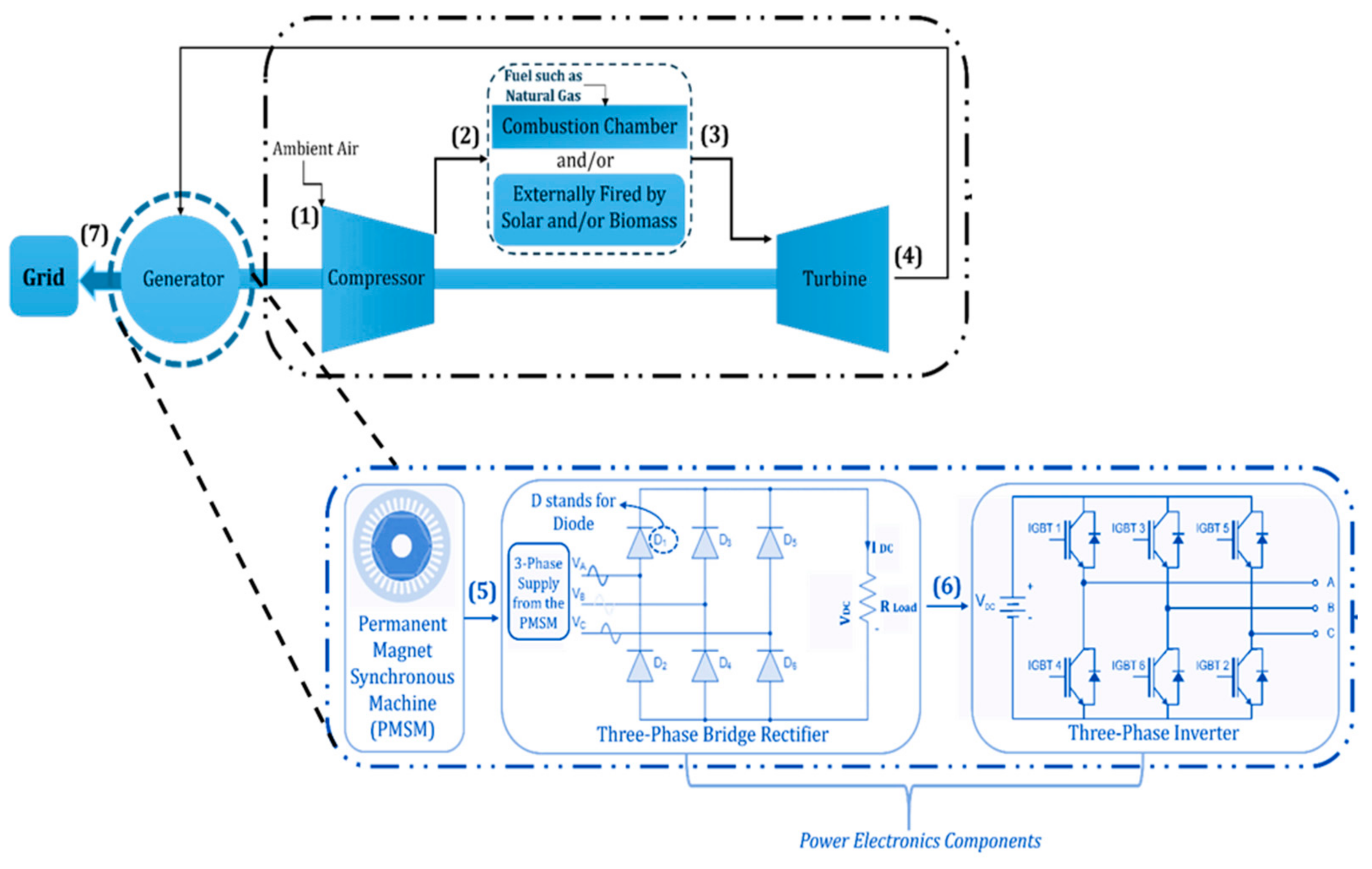
Figure 2.
Photograph of a T100 Ansaldo Energia micro gas turbine unit at the University of Genova’s Savona Campus (2022).
Figure 2.
Photograph of a T100 Ansaldo Energia micro gas turbine unit at the University of Genova’s Savona Campus (2022).
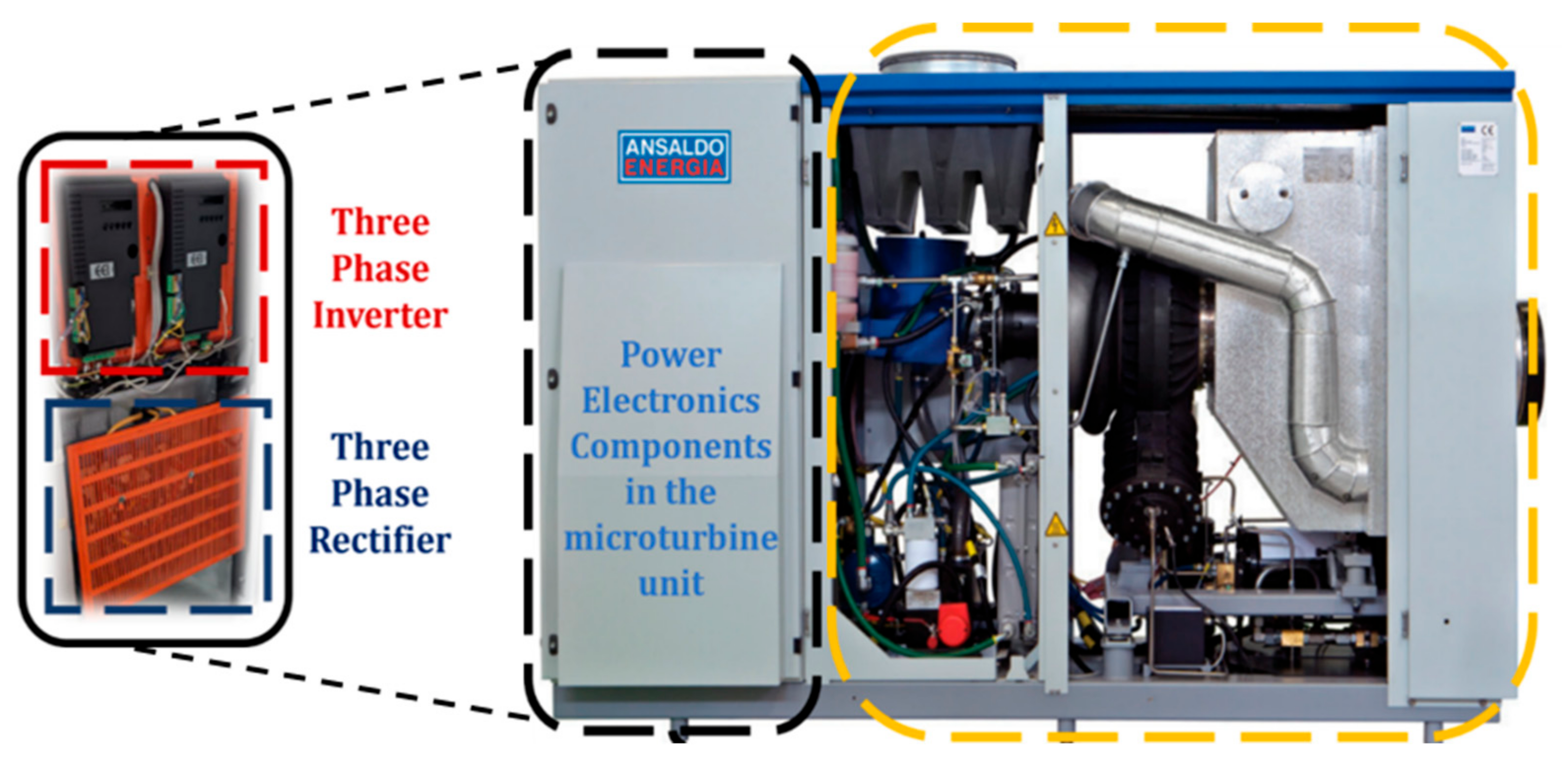
Figure 3.
3D model of the 103 µm silicon cube (in yellow) and 9.2 µm silicon carbide column (in blue), both at the same voltage/performance level.
Figure 3.
3D model of the 103 µm silicon cube (in yellow) and 9.2 µm silicon carbide column (in blue), both at the same voltage/performance level.
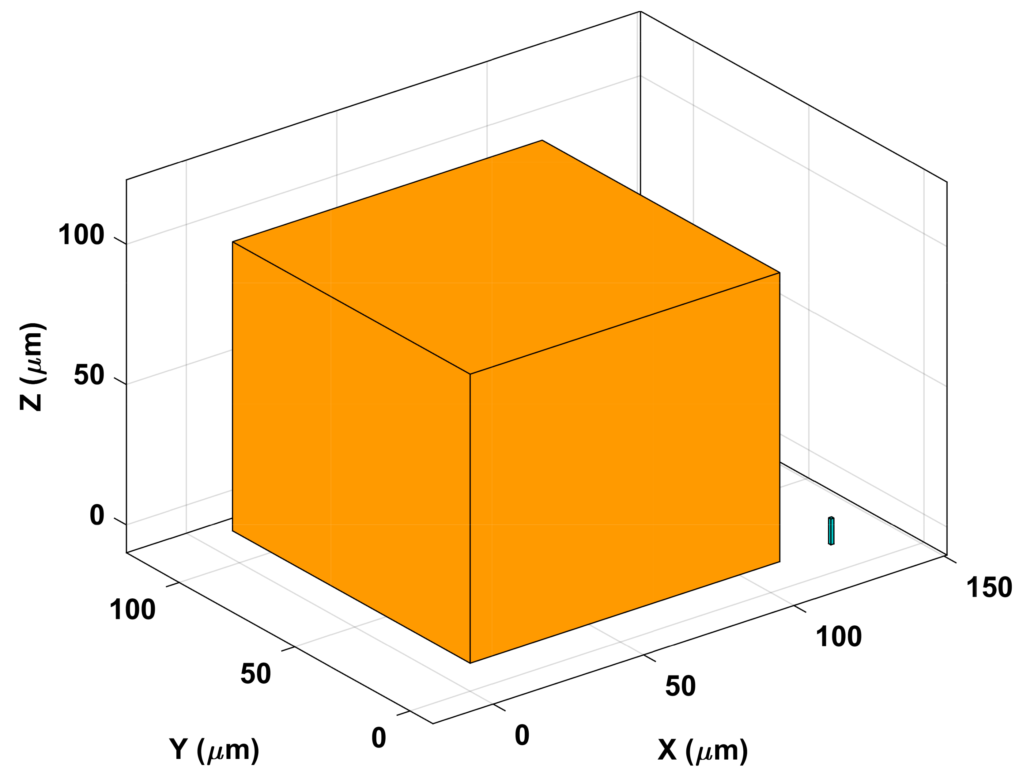
Figure 4.
Power density comparison of the overall MGT system for silicon-based and silicon carbide-based IGBTs.
Figure 4.
Power density comparison of the overall MGT system for silicon-based and silicon carbide-based IGBTs.

Figure 5.
Inverter volume of AE T100 MGT vs output power.
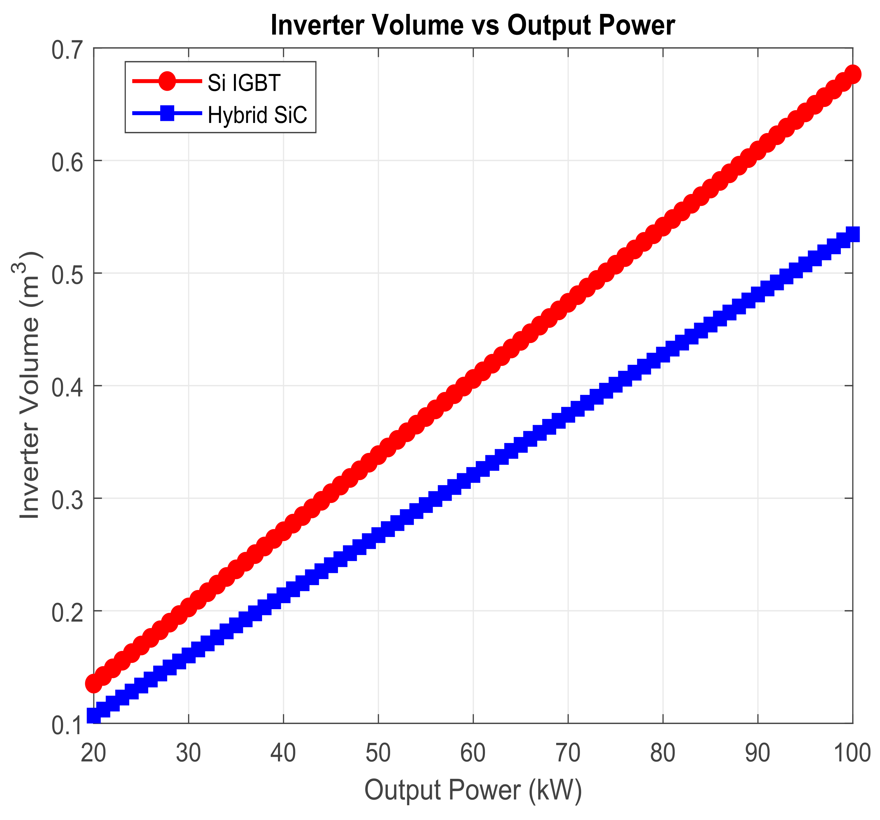
Figure 6.
Inverter power density of AE T100 MGT vs output power.
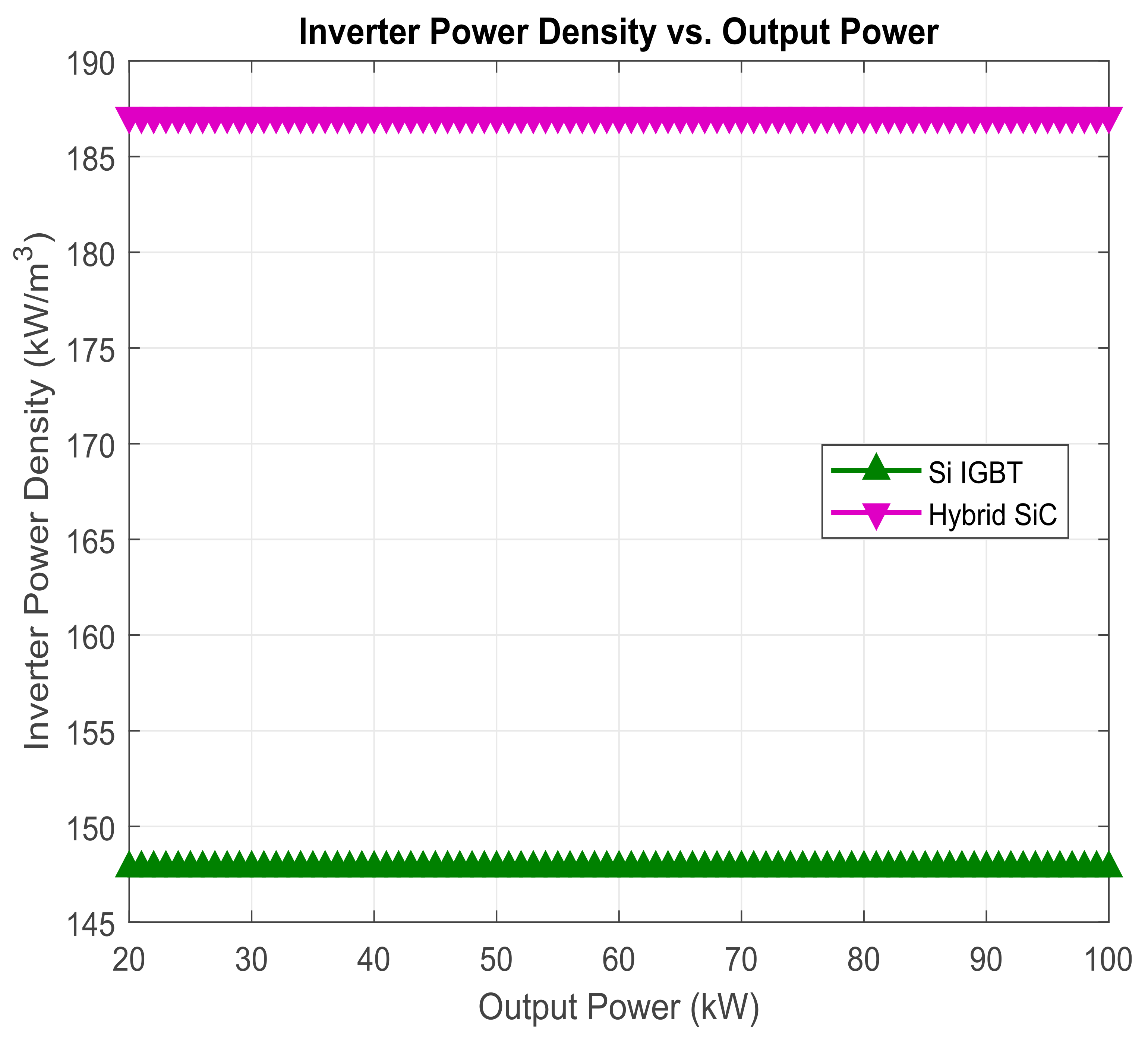
Figure 7.
Overall AE T100 MGT unit volume vs output power.
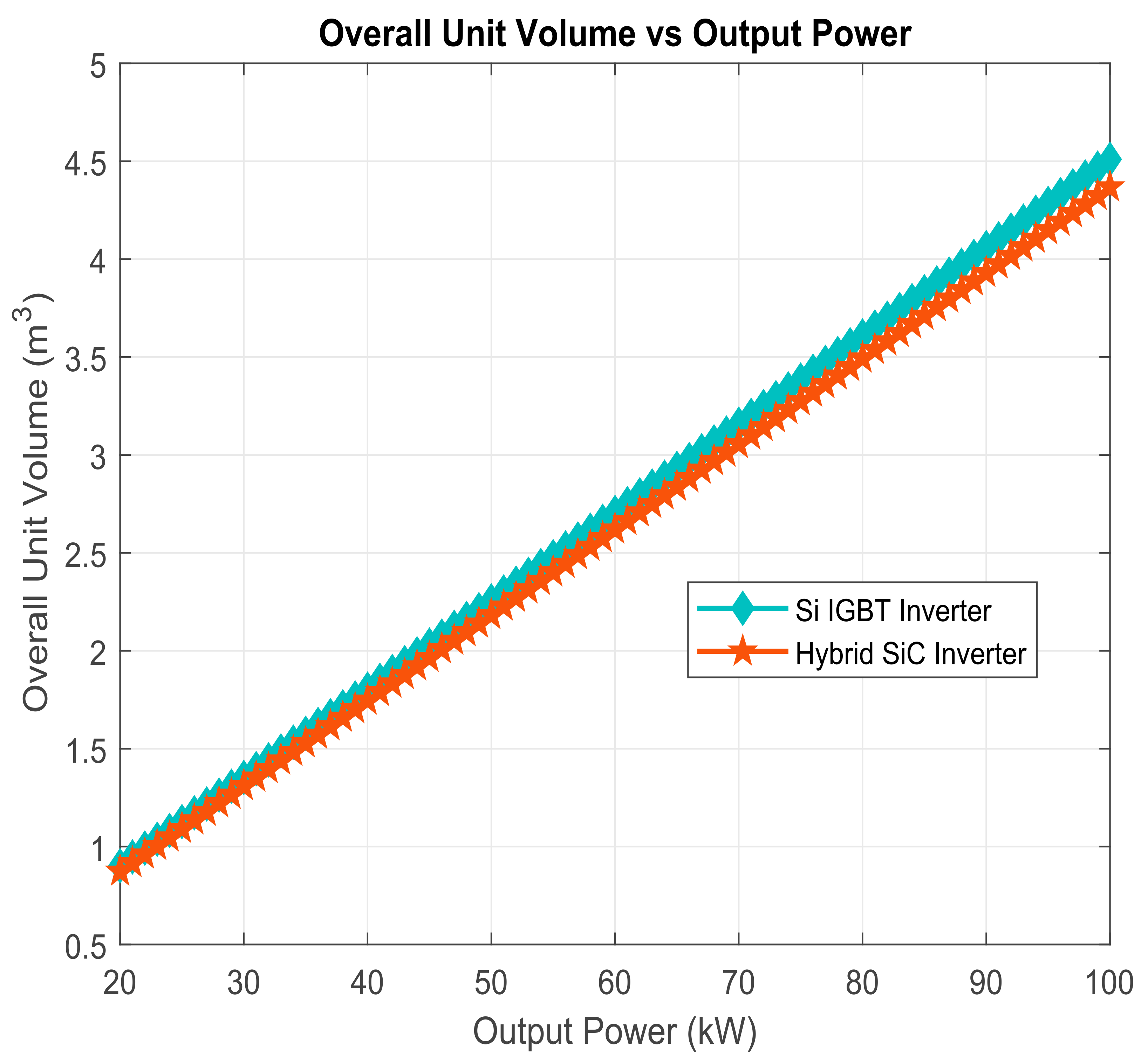
Figure 8.
Overall AE T100 MGT unit power density vs output power.
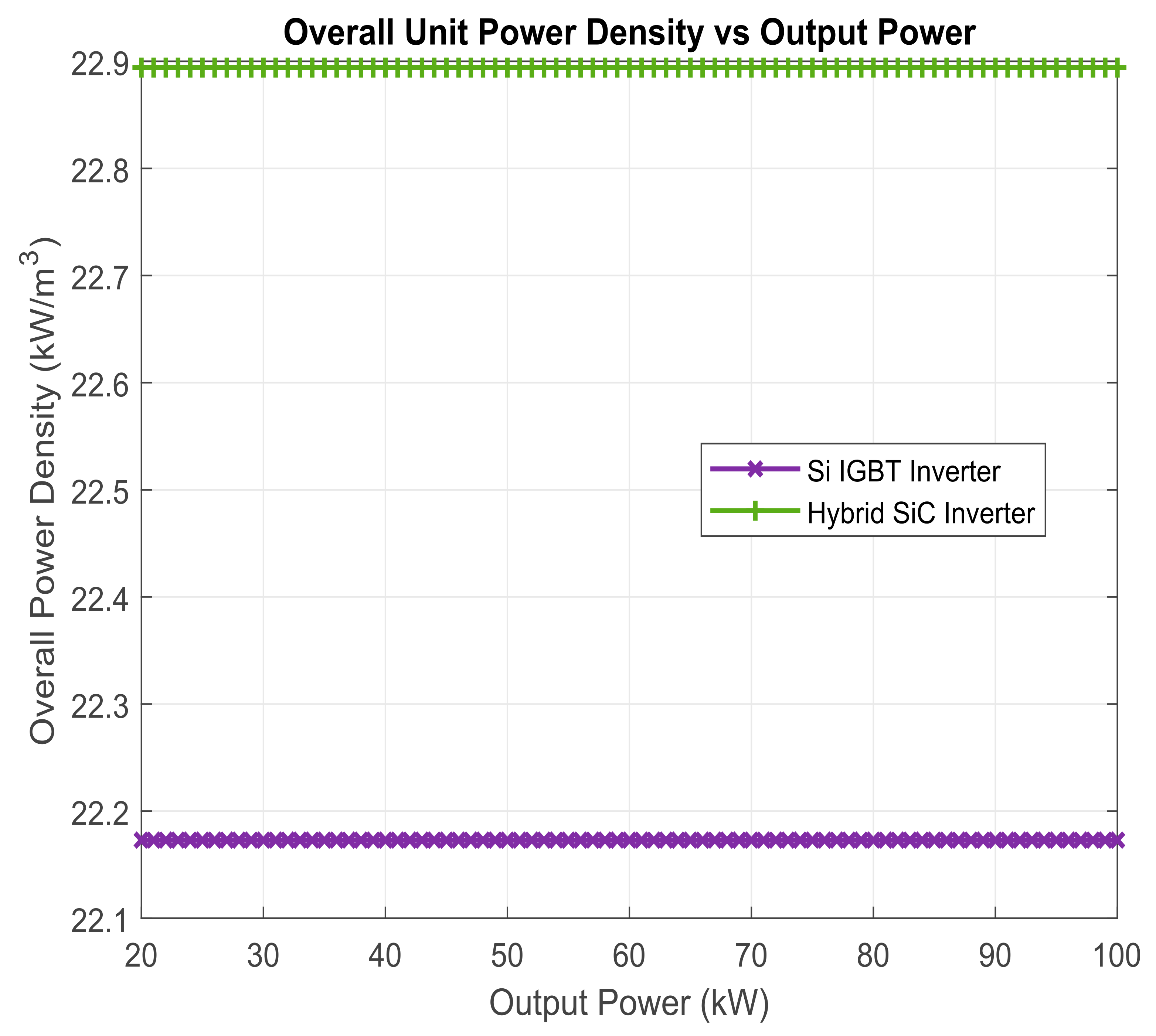
Figure 9.
Comparative volume reductions and power density improvements at 100 kW: conventional silicon vs hybrid silicon carbide IGBTS in the AE T100 micro gas turbine.
Figure 9.
Comparative volume reductions and power density improvements at 100 kW: conventional silicon vs hybrid silicon carbide IGBTS in the AE T100 micro gas turbine.
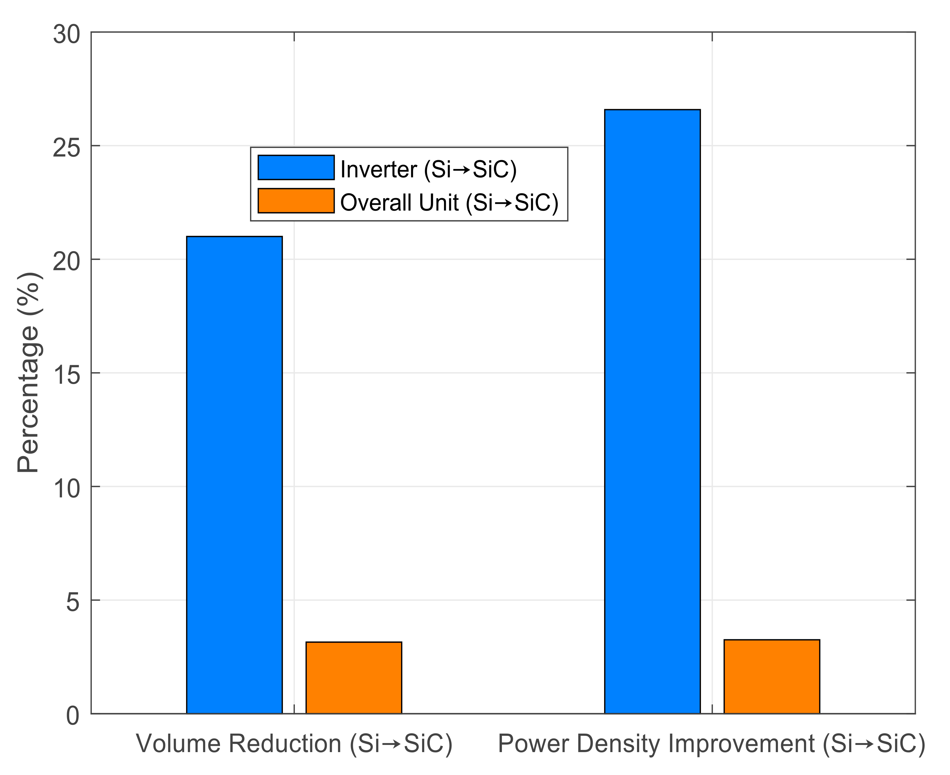

Table 1.
Parameter ratios for a 1200 V SiC MOSFET relative to silicon.
| Comparative Parameters | Silicon Carbide Parameter Value as a Function of Silicon |
|---|---|
| area | silicon carbide = 1/626 silicon |
| thickness | silicon carbide = 1/11 silicon |
| capacitance | silicon carbide = 1/46 silicon |
| thermal resistance | silicon carbide = 17 silicon |
Disclaimer/Publisher’s Note: The statements, opinions and data contained in all publications are solely those of the individual author(s) and contributor(s) and not of MDPI and/or the editor(s). MDPI and/or the editor(s) disclaim responsibility for any injury to people or property resulting from any ideas, methods, instructions or products referred to in the content. |
© 2025 by the author. Licensee MDPI, Basel, Switzerland. This article is an open access article distributed under the terms and conditions of the Creative Commons Attribution (CC BY) license (http://creativecommons.org/licenses/by/4.0/).
Copyright: This open access article is published under a Creative Commons CC BY 4.0 license, which permit the free download, distribution, and reuse, provided that the author and preprint are cited in any reuse.


