
Submitted:
10 May 2025
Posted:
12 May 2025
You are already at the latest version
Abstract
The thin and straight horn of the ultrasonic transducer is located in the center of the thick transducer, so that the tool tip of the ultrasonic vibration turning tool holder cannot be located on the outermost side of the entire tool holder, which leads to the structural interference between the tool holder and the part during turning. In order to solve this problem, this paper proposes a longitudinal-bending elliptical vibration ultrasonic transducer with bending horn for ultrasonic vibration-assisted cutting (UVAC). A-type transducer can be used for UVAC of external surface, and B-type transducer can be used for UVAC of internal cavity. The maximum peak-peak amplitudes of longitudinal vibration and bending vibration for A-type transducer are 14μm and 16μm, respectively. The maximum peak-peak amplitudes of longitudinal vibration and bending vibration for B-type transducer are 17μm and 21μm, respectively. Such a large amplitude can fully meet the needs of UVAC. When using ultrasonic transducer with bending horn for partial separation continuous high-speed elliptic ultrasonic vibration cutting (HEUVC), compared with conventional cutting (CC), HEUVC can improve the tool life by 65.74% for A-type transducer, HEUVC can improve the tool life by 44.62% for B-type transducer.
Keywords:
Structural interference
; Bending horn
; Longitudinal-bending
; Elliptical vibration ultrasonic transducer
; Ultrasonic vibration-assisted cutting
1. Introduction
UVAC can reduce cutting temperature and cutting force and improve tool life and surface integrity by separation effect, so it is widely used in cutting difficult-to-machine materials [1,2,3,4]. However, the application of ultrasonic vibration-assisted turning in practical production is limited because the ultrasonic vibration turning tool holder will interfere with the parts in structure [5,6]. The thin and straight horn of the ultrasonic transducer is located in the center of the thick transducer, so that the tool tip of the ultrasonic vibration turning tool holder cannot be located on the outermost side of the entire tool holder, which leads to the structural interference between the tool holder and the part during turning. In order to solve this problem, an ultrasonic vibration transducer with a bending horn must be designed for ultrasonic vibration-assisted turning.
In traditional ultrasonic vibration cutting (UVC), the tool vibrates along the cutting speed direction. In elliptic ultrasonic vibration cutting (EUVC), the tool has vibration components along cutting speed and cutting depth. There is a critical cutting speed limit in UVC and EUVC, and the material removal rate (MRR) is low [7,8]. Zhang et al. proposed high-speed ultrasonic vibration cutting (HUVC), which improved the cutting speed several times [9]. However, due to the limitation of critical feed, the MRR is also low. Zhang et al. [10] proposed partial separation continuous high-speed ultrasonic vibration cutting (C-HUVC), which solved the problem of low MRR in UVAC. In HUVC and C-HUVC, the tool vibrates along the feed direction. When the tool vibrates along the cutting speed direction or the feeding direction, the tool impacts the metal of the cutting layer, and the impact force is small. However, when the tool vibrates along the cutting depth direction, the tool impacts the workpiece radially, which leads to a large impact force, so the tool wear is intensified.
In the machining of parts, the step usually needs both cylindrical turning and face turning, and the tool with unidirectional vibration usually encounters the situation that the tool impacts the workpiece radially, so the mode of elliptical ultrasonic vibration in the base plane is adopted in this paper. The tool that vibrates elliptically in the base plane has vibration components along the feed and cutting depth. To solve the problems of conventional ultrasonic turning tool holder in terms of mechanical structure and machining technology, a longitudinal-bending elliptical vibration ultrasonic transducer with bending horn is proposed, which will be used for HEUVC.
Since 1975, HORTON et al. [11] proposed the use of piezosurgery for the treatment of oral diseases, today the piezosurgery with bending horn has been widely used in clinical practice [12,13,14,15]. Piezosurgery uses the principle of high-intensity focused ultrasound to cut biological tissues [16,17]. The strength of biological tissues is low, so the cutting force of cutting biological tissues is small. The diameter of the horn of the piezosurgery is only a few mm, so the stiffness is small. To solve the problem of changing the direction of longitudinal vibration when ultrasonic cleaning the inner surface of bending pipes, He et al. [18] proposed an design method of longitudinal vibration horn with included angle structure in 2017. In their design, two straight horns with a radius of 7.5mm is assembled together by threads to form a bending horn. The stiffness of the horn of the transducer is too small to be used for UVAC, and the vibration direction of the horn is the simplest longitudinal vibration.
It is difficult to adjust the shape of ellipse for single-drive transducer, so this paper adopts double-drive elliptical ultrasonic vibration mode [19,20]. Elliptical vibration ultrasonic transducers are usually designed by simulation method [21,22,23] and analytical method [24,25,26]. The matching of the frequencies of longitudinal vibration and bending vibration in the elliptical vibration ultrasonic transducer is mainly realized by adjusting the structural size [27,28,29]. The transducer is capacitive, which requires matching inductance to increase the amplitude of the transducer. According to the impedance matching theory put forward by Jiang et al. [30], the transducer can still obtain 70% of the maximum amplitude when it vibrates within the range of 0.4kHz above and below the optimal resonance frequency. This theory can be used to match the frequencies of transducers with two different resonant frequencies so that the frequencies of longitudinal vibration and bending vibration are the same.
Ultrasonic transducer with bending horn has been applied in cutting biological tissues and ultrasonic cleaning of bent pipes, but it has not been studied and applied in UVAC. The cutting force for cutting difficult-to-machine materials is usually several hundred newtons, and the cross section of the conventional turning tool holder is usually 25cm×25cm or 32cm×32cm, and the horn of the above transducer is too thin to meet the use. It is an unknown problem whether the transducer can produce the amplitude required by turning when the stiffness of the transducer is improved. Whether the transducer can be matched into an elliptical vibration transducer by matching the frequencies of longitudinal vibration and bending vibration is the second problem. The bending angle of the horn will affect the direction of vibration propagation, and whether the transducer can be matched into a transducer with a circular trajectory by matching the directions of longitudinal vibration and bending vibration is the third problem. This paper aims to solve the above three problems.
In this paper, firstly, through brief theoretical analysis, the relationship between the resonant angular frequency of longitudinal vibration and bending vibration in the beam and the structural size of the beam is determined, which provides a basis for adjusting the structural parameters of the horn in the simulation design of ultrasonic transducer. Secondly, through induction and summary, the simulation design flow chart of longitudinal-bending elliptical vibration ultrasonic transducer with bending horn is put forward. Through the simulation design, the structural dimensions of the ultrasonic transducer are obtained. Finally, the correctness of simulation design is verified by vibration test, and the adaptability of ultrasonic transducer and the feasibility of cutting process are verified by cutting test.
2. Transducer and Application
Figure 1 shows problems and solutions of structural interference in ultrasonic vibration turning. As shown in Figure 1a, there is a problem of structural interference when turning with conventional ultrasonic turning tool holder. To increase the output amplitude of the transducer, the horn is usually thinner than the transducer. The transducer is generally a revolving body, and the horn is located in the revolving center of the transducer, which makes the tool tip of the ultrasonic vibration turning tool holder unable to be located at the outermost side of the whole tool holder, which leads to the structural interference between the transducer and the part during turning. To solve this problem, an ultrasonic transducer with a bending horn can be adopted, as shown in Figure 1b. It is also possible to rotate the tool holder without bending the horn so that the tool tip is at the outermost side, but this method will make the tool holder larger and less feasible. Elliptical ultrasonic vibration transducer with bending horn completely solves the problem of structural interference, and is suitable for UVAC of external surface of parts.
UVAC can periodically open the cutting area, which enables the coolant to enter the cutting area to lubricate the cooling tool and the machined surface, thus reducing the cutting temperature and cutting force and improving the tool life and surface integrity, so it is widely used in cutting difficult-to-machine materials. There are many difficult-to-machine materials in aerospace field, and UVAC has broad application prospects. Figure 1c is a schematic diagram of turning the internal cavity in an aero-engine turbine disk with a conventional tool holder. There are many cavity structures in aero-engine parts, and the straight turning tool holder can't enter them, so it can only be designed into various bending structure. To apply the UVAC method to the turning of aero-engine parts, it is necessary to design an ultrasonic transducer with a bending horn. Due to the complex structure of the cavity, the design range of the tool front end is limited. The tool front end of the ultrasonic tool holder should be basically the same as that of the conventional tool holder. Figure 1d is a schematic diagram of an elliptical ultrasonic vibration transducer with a bending horn turning the internal cavity of a turbine disk.
3. Finite Element Design
3.1. Theoretical Analysis
This part mainly determines the relationship between the resonant angular frequency of bending wave and longitudinal wave in the beam and the structural size of the beam through brief theoretical analysis, which provides a basis for structural parameter adjustment of horn in simulation design.
A beam with two free ends satisfies the following equation (1) at resonance:
where, is the length of the beam, is the wavelength, and is the number of half wavelengths in the beam at resonance.
The wavelength , frequency f and sound velocity c satisfy the following equation (2):
Equation (3) can be obtained from equation (1) and equation (2):
where, is the angular frequency of vibration.
The longitudinal wave velocity in the beam is:
where, is elastic modulus and is density.
The sound velocity of bending wave in the beam is:
where, is the radius of gyration of the section.
where, is the moment of inertia of section, is the area of section, is the width of section, and is the height of section.
Substituting equation (4) into equation (3) can obtain the angular frequency equation of longitudinal wave resonance in the beam:
Substituting equation (5) into equation (3) can obtain the angular frequency equation of bending wave resonance in the beam:
According to equation (9), the resonant frequency of longitudinal vibration in a beam is inversely proportional to its length. According to equation (10), the resonant frequency of bending vibration in a beam is inversely proportional to the square of its length and directly proportional to the width of the beam section. Therefore, when matching the frequencies of longitudinal vibration and bending vibration in elliptical vibration ultrasonic transducer, firstly, the length of the horn is designed properly, so that there is a small difference between the frequencies of longitudinal vibration and bending vibration, and then the frequency of bending vibration is close to the frequency of longitudinal vibration by adjusting the section width of the horn. Finally, the longitudinal vibration and bending vibration are matched to one frequency by impedance matching.
3.2. Simulation Design
Figure 2 shows two kinds of elliptical vibration ultrasonic transducer with bending horn. A-type transducer can be used for ultrasonic vibration-assisted turning of external surface, and B-type transducer can be used for ultrasonic vibration-assisted turning of internal cavity. In the designed transducer, the horn, the flange, the front cap and the bolt are a part, and the piezoelectric ceramic piece and the copper electrode are strung on the bolt and pressed by the end cap. Four half-piece piezoelectric ceramic plates near the front cap are used to generate bending vibration, and two complete piezoelectric ceramic plates near the end cap are used to generate longitudinal vibration. The diameter of piezoelectric ceramic plate is required to be less than a quarter of the wavelength of sound waves in ceramic materials, and ceramic pieces with larger diameters should be selected to carry enough energy. In this paper, the piezoelectric ceramic plates with an outer diameter of 45mm, an inner diameter of 15mm and a thickness of 5mm are selected.
In Figure 2c, there are bolt holes for fixing the transducer and fixture, sealing groove for installing O-ring and arc-shaped damping groove on the flange. The arc-shaped damping groove is formed by removing excess metal after the flange has a margin of 0.7mm, and its function is to weaken the restraint of the flange on the transducer. Minimize the flange size with sufficient rigidity, and take and . According to the experience, the resonance effect of transducer is good when the length of the end cap is . For bending vibration, the front cap should be designed as thin as possible. In this paper, the front cap is 4mm thicker than the flange and. The wavelength of the beam (made of 42CrMo) is 258cm when it resonates at 20kHz. In order to ensure the transducer has sufficient stiffness, the longitudinal vibration of the elliptical vibration ultrasonic transducer with bending horn designed in this paper is half wavelength. Figure 2d is a schematic diagram of the horn of B-type transducer, and the tool is clamped and fixed on the horn.
For A-type transducer, the known parameters and the parameters to be solved are listed in Table 1. m is the distance difference between the outside of the front end of the horn and the outside of the flange in the axial direction of the transducer. is the frequency of longitudinal vibration and is the frequency of bending vibration. The units of and are kHz, the units of α and are °, and the units of other parameters are mm. Figure 3a is the flow chart of simulation design for A-type transducer. The general design idea is as follows: The first step is to design a half-wavelength longitudinal vibration transducer with a straight horn. Firstly, the section size of the horn is estimated, and then the length of horn is calculated in a certain frequency range. The calculation here is based on the principle of half-wavelength longitudinal vibration, that is, the length of the horn should be the half-wavelength length of the sound wave in the material at the working frequency. The second step is to match the half-wavelength longitudinal vibration transducer with a straight horn into a longitudinal-bending hybrid elliptical vibration ultrasonic transducer. By adjusting the section size of the horn, the resonance frequencies of longitudinal vibration and bending vibration are close. The third step is to design an elliptical vibration ultrasonic transducer with a bending horn. Bending the horn makes the axis of the horn and the axis of the transducer form a certain included angle α. By adjusting the value of α, the directions of longitudinal vibration and bending vibration can be nearly perpendicular to each other. Further, the distance m from the front end of the horn to the outermost side of the transducer is adjusted by adjusting the length of the horn. The fourth step is to perform a final check of the designed elliptical vibration ultrasonic transducer with bending horn. The ultimate goal of the design is to make the two paths of vibration (longitudinal vibration and bending vibration) nearly the same in frequency and nearly perpendicular to each other in vibration direction. At the same time, the front end of the horn extends out of the outermost side of the transducer for a certain distance to ensure that the tool holder does not interfere with the workpiece during ultrasonic vibration-assisted turning.
For B-type transducer, the known parameters and the parameters to be solved are listed in Table 2. is the frequency of longitudinal vibration and is the frequency of bending vibration. The units of and are kHz, the units of α and are °, and the units of other parameters are mm. To avoid the structural interference between the horn and the turbine disk, the front structure of the horn is kept consistent with that of the conventional turning tool holder. The frequency matching and vibration direction matching of elliptical vibration ultrasonic transducer are carried out by adjusting the structural size of the straight part of the horn. Figure 3b is the flow chart of simulation design for B-type transducer. The general design idea is as follows: The first step is to design a half-wavelength longitudinal vibration transducer with a bending horn. Firstly, the section size of the horn is estimated, and then the length of the straight part of the horn is calculated within a certain frequency range. The second step is to match a half-wavelength longitudinal vibration transducer with a bending horn into a longitudinal-bending hybrid elliptical vibration ultrasonic transducer. By adjusting the section size of the straight part of the horn, the resonance frequencies of longitudinal vibration and bending vibration are close, and the vibration directions of longitudinal vibration and bending vibration are nearly perpendicular to each other. The third step is to perform a final check of the designed elliptical vibration ultrasonic transducer with bending horn. The ultimate goal of the design is to make the longitudinal vibration and bending vibration nearly the same in frequency and nearly perpendicular to each other in vibration direction. At the same time, it is ensured that the ultrasonic tool holder does not interfere with the turbine disk during ultrasonic vibration-assisted turning.
4. Results and Discussion
4.1. Simulation Design Results
Figure 4 and Figure 5 are the simulation results of A-type transducer. Figure 4 shows influence of structural dimensions of A-type transducer on resonance frequency. The initial section size is estimated to be according to the required stiffness and size requirements of the horn, and then the influence of the length of horn on the resonance frequency of longitudinal vibration and bending vibration is analyzed. As can be seen from Figure 4a, with the shortening of the length of horn, the resonant frequencies of bending vibration and longitudinal vibration increases, and the frequency of bending vibration increases faster so that the resonant frequencies of bending vibration and longitudinal vibration can be equal. In order to ensure that the horn can extend out of the side of the transducer after bending, and at the same time consider the influence of the length of horn on the stiffness, is determined.
On the basis of obtaining the length of the horn, the influence of the width of horn d on the resonance frequency of longitudinal vibration and bending vibration is studied. As can be seen from Figure 4b, with the increase of the width of horn, the resonant frequency of bending vibration increases obviously, while the resonant frequency of longitudinal vibration increases slightly. Therefore, the resonant frequencies of bending vibration and longitudinal vibration can be close by changing the width of horn.
On the basis of obtaining the length of horn, the influence of the thickness of horn h on the resonance frequency of longitudinal vibration and bending vibration is studied. It can be found from Figure 4c that with the increase of thickness of horn, the resonant frequencies of bending vibration and longitudinal vibration have the same changing trend, so it is impossible to make the resonant frequencies of bending vibration and longitudinal vibration close by changing thickness of horn. The thickness of horn has little influence on the resonant frequency, but it has great influence on the stiffness of the horn, so that the thickness and width of the horn are equal to meet the requirements of frequency matching and stiffness at the same time. In Figure 4d, with the increase of the section size d and h of the horn, the resonance frequencies of bending vibration and longitudinal vibration increase, and the resonance frequencies of bending vibration increases faster so that the resonance frequencies of bending vibration and longitudinal vibration can be equal.
The influence of the length, width and thickness of the horn in Figure 4 on the resonant frequency of the bending vibration and longitudinal vibration corresponds to equation (9) and equation (10). Equations (9) and (10) are obtained under the condition of pure bending beam. From equation (9) and equation (10), it can be seen that the angular frequency of longitudinal vibration is inversely proportional to the length of the horn, and the angular frequency of bending vibration is inversely proportional to the square of the length of the horn. In Figure 4a, as the length of the horn decreases, the resonant frequency of bending vibration increases faster than that of longitudinal vibration. Equation (9) is independent of the width of the horn, and the angular frequency of bending vibration in equation (10) is proportional to the width of the horn. In Figure 4b, the resonant frequency of longitudinal vibration does not change much with the increase of the width of the horn, while the resonant frequency of bending vibration increases with the increase of the width of the horn. Equations (9) and (10) are independent of the thickness of the horn. In Figure 4c, the resonant frequencies of longitudinal vibration and bending vibration do not change much with the increase of the thickness of the horn.
The transducer with and is selected as an elliptical vibration ultrasonic transducer with a straight horn. The resonance frequencies of longitudinal vibration and bending vibration are 17.858kHz and 18.058kHz, respectively. After bending the horn for a certain angle, an elliptical vibration ultrasonic transducer with a bending horn can be obtained. Considering that the difference between 17.858kHz and 18.058kHz is only 0.2kHz, and the resonant frequency of the transducer will change after the horn is bent to a certain angle, it is only required that the resonant frequencies of longitudinal vibration and bending vibration are close, but not equal.
Figure 5 shows the influence of the bending angle α of the horn on the resonance characteristics of the transducer. Figure 5a studies the influence of bending angle α on resonance frequency. In Figure 5a, when α increases from 0° to 50°, the resonant frequency of bending vibration increases slowly. The resonant frequency of longitudinal vibration increases slowly with α increasing from 0° to 25°, and increases rapidly with α increasing from 25° to 50°. In the case of small α, the influence of the bending angle α of the horn on the frequency matching can be ignored, and in the case of large α, it is not conducive to the frequency matching.
As shown in Figure 2a, θ and γ are the included angles between the vibration direction of point A and the axis of the transducer in bending vibration and longitudinal vibration, respectively. Figure 5b studies the influence of bending angle α on vibration direction. In Figure 5b, when α increases from 10° to 50°, the angle θ of the vibration direction of bending vibration slowly increases. The angle γ of the vibration direction of longitudinal vibration increases rapidly with α increasing from 10° to 20°, and slowly increases with α increasing from 20° to 50°.
The bending of the horn causes the asymmetry of the structure, which makes the vibration directions of bending vibration and longitudinal vibration incline to the bending direction of the horn. Because of the different inclination degrees of the vibration directions of bending vibration and longitudinal vibration, the vibration directions of bending vibration and longitudinal vibration are not vertical. Considering the influence of the bending angle α of the horn on the resonant frequency and vibration direction of the transducer, is determined as the appropriate bending angle of the horn. After the optimization design, the structural parameters of the A-type transducer satisfying Figure 3a are shown in Table 4.
Figure 6 is the simulation results of B-type transducer. Figure 6 shows influence of structural dimensions of B-type transducer on resonance frequency. The initial width of straight horn is estimated to be according to the required stiffness and size requirements of the horn, and then the influence of the length of straight horn on the resonance frequency of longitudinal vibration and bending vibration is analyzed. As can be seen from Figure 6a, with the shortening of the length of straight horn, the resonant frequencies of bending vibration and longitudinal vibration increases, and the frequency of bending vibration increases faster so that the resonant frequencies of bending vibration and longitudinal vibration can be equal.
On the basis of obtaining the length of the horn, the influence of the width of horn d on the resonance frequency of longitudinal vibration and bending vibration is studied. As can be seen from Figure 6b, with the increase of the width of horn, the resonant frequency of bending vibration increases obviously, while the resonant frequency of longitudinal vibration increases slightly. Therefore, the resonant frequencies of bending vibration and longitudinal vibration can be close by changing the width of horn. The influence of the length and width of the straight horn in Figure 6 on the resonant frequency of the bending vibration and longitudinal vibration corresponds to equation (9) and equation (10). The front structure of the horn of B-type transducer is too thin, which will amplify the local vibration, it is difficult to judge the direction of the vibration, so the influence of the structural size of the horn on the direction of the vibration is not discussed here. After the optimization design, the structural parameters of the B-type transducer satisfying Figure 3b are shown in Table 5.
The modal analysis results of the optimized longitudinal-bending elliptical vibration ultrasonic transducer with bending horn are shown in Figure 7. Figure 7a,c show the first longitudinal vibration mode, and the node is located in the flange. The mode shows that the vibration of the end cap is small, and it can also be used as a clamping point. In practice, clamping the end cap has little effect on the resonance characteristics. Figure 7b,d show the second bending vibration mode, and the nodes are located in the flange and the end cap. Therefore, the transducer can be fixed by the flange and the end cap.
4.2. Vibration Test
The transducers corresponding to the structural parameters in Table 4 and Table 5 are manufactured and assembled together according to the assembly relationship in Figure 2. The resonant frequency of the transducer is measured by PV520A impedance analyzer developed by Tsinghua University. The resonant frequencies of longitudinal vibration and bending vibration of A-type transducer are 18.332kHz and 18.290kHz, respectively, and the difference between the designed and measured resonant frequencies of longitudinal vibration and bending vibration is 0.76% and 0.19%, respectively. The resonance frequencies of longitudinal vibration and bending vibration of B-type transducer are 22.328kHz and 22.678kHz respectively, and the difference between the designed and measured resonance frequencies of longitudinal vibration and bending vibration is 9.51% and 6.74% respectively.
Figure 8 shows measuring device for vibration amplitude and vibration direction. The transducer is excited by applying voltage from ultrasonic power supply, and the vibration amplitude is measured simultaneously in horizontal and vertical directions by a laser micrometer. When the vibration in a single direction is excited (exciting longitudinal vibration or bending vibration), the vibration amplitude and vibration direction can be obtained by synthesizing the amplitude measured in the horizontal and vertical directions. When longitudinal vibration and bending vibration are excited at the same time, the elliptical vibration trajectory of the tool tip can be obtained by synthesizing the amplitudes measured in the horizontal and vertical directions.
For A-type transducer, the direction angle of longitudinal vibration is , the direction angle of bending vibration is , and the included angle between the directions of longitudinal vibration and bending vibration is . The difference between the designed and the measured included angle between the directions of longitudinal vibration and bending vibration is 7.93%. For B-type transducer, the direction angle of longitudinal vibration is , the direction angle of bending vibration is , and the included angle between the directions of longitudinal vibration and bending vibration is . The difference between the designed and the measured included angle between the directions of longitudinal vibration and bending vibration is 9.72%.
The transducer is capacitive, which requires matching inductance to make the circuit resonate and thus increase the amplitude of the transducer. The appropriate matching inductance can be determined by debugging the transducer. Figure 9 shows the Peak-peak amplitudes of transducer at different resonant frequencies with inductance. As can be seen from Figure 9, there is a resonance frequency with the largest amplitude for both longitudinal vibration and bending vibration, which is lower than the mechanical resonance frequency measured by the impedance analyzer. The maximum peak-peak amplitudes of longitudinal vibration and bending vibration for A-type transducer are 14μm and 16μm, respectively. The maximum peak-peak amplitudes of longitudinal vibration and bending vibration for B-type transducer are 17μm and 21μm, respectively. In order to make the resonance frequencies of longitudinal vibration and bending vibration equal and their amplitudes as large as possible, 17.8kHz is selected as the resonance frequency of elliptical vibration ultrasonic transducer for A-type transducer and 21.4kHz is selected as the resonance frequency of elliptical vibration ultrasonic transducer for B-type transducer.
Let the longitudinal vibration of the elliptical vibration ultrasonic transducer vibrate along the x axis, and its bending vibration vibrates in the xOy plane, so the vibration equation of the tool tip can be obtained as follows:
where, B is the amplitude of longitudinal vibration, μm; C is the amplitude of bending vibration, μm; F is the frequency of longitudinal vibration and bending vibration, Hz; t is time, s; is the phase difference of bending vibration compared with longitudinal vibration, ;
Figure 10a shows the vibration trajectories of the tool tip under different phase differences for A-type transducer at and . Because there is an included angle of between the directions of longitudinal vibration and bending vibration, the trajectory of the tool tip is an oblique oblate ellipse when the phase difference is , but it is approximately circular when the phase difference is . Figure 10b shows the vibration trajectories of the tool tip under different phase differences for B-type transducer at and . Because there is an included angle of between the directions of longitudinal vibration and bending vibration, the trajectory of the tool tip is an oblique oblate ellipse when the phase difference is , but it is approximately circular when the phase difference is . Figure 11 shows the measured vibration trajectory of the tool tip for A-type transducer at and . Figure 12 shows the measured vibration trajectory of the tool tip for B-type transducer at and . The elliptical trajectories in Figure 11 and Figure 12 are all approximately circular.
4.3. Machining Test
It is difficult to open the cutting zone in continuous cutting, so high cutting temperature and cutting force limit the tool life when cutting difficult-to-machine materials. Intermittent UVAC can reduce the cutting temperature and cutting force by opening the cutting area to improve the tool life, so it is widely used in cutting difficult-to-machine materials. However, intermittent cutting makes the MRR of UVAC low. Zhang et al. [10] put forward the partial separation continuous high-speed ultrasonic vibration cutting method, which can open the cutting area while cutting continuously, greatly improving the tool life and MRR. In this paper, an elliptical vibration ultrasonic transducer with bending horn is used to study the partial separation continuous high-speed elliptical ultrasonic vibration cutting Inconel 718.
Figure 13 shows experimental setup in HEUVC. In Figure 13a, a rhombic-type AlTiN-coated cemented carbide insert from Iscar (VCMT 160408-SM IC804) was mounted on the A-type transducer. The tool tip of A-type transducer vibrates elliptically at the frequency of 17.8kHz in the tool base. In Figure 13b, a TiAlN+AlTiN+TiN-coated cemented carbide insert from Iscar (TAGB 630Y IC808) was mounted on the B-type transducer. The tool tip of B-type transducer vibrates elliptically at the frequency of 21.4kHz in the tool base. A water-soluble emulsion is applied as a coolant on the rake face.
The comparative experiments of HEUVC and CC were carried out on CNC lathe. Table 6 contains all the machining parameters. In this paper, the finishing experiment of Inconel 718 is carried out, and the cutting parameters are set according to the requirements of finishing. When the maximum flank wear VBmax = 0.3 mm, the cutting experiment is stopped. Three experiments were carried out to obtain the average of the experimental results.
Figure 14 show effect of cutting distance on flank wear when an elliptical vibration ultrasonic transducer with bending horn is used to study the partial separation continuous high-speed elliptical ultrasonic vibration cutting Inconel 718. HEUVC method can partially open the cutting area in the process of continuous cutting, so that the coolant can enter the cutting area to cool and lubricate the tool and workpiece, reduce the cutting temperature and cutting force, and thus prolong the tool life. Compared with CC, HEUVC can improve the tool life by 65.74% when cutting with A-type transducer. Compared with CC, HEUVC can improve the tool life by 44.62% when cutting with B-type transducer.
Figure 15 show topographies of machined surface of Inconel 718. Figure 15a,b are topographies of machined surface in CC. The existence of chatter marks is not observed in Figure 15a,b, which indicates that the designed ultrasonic vibration tool holder has sufficient rigidity. Figure 15c,d are topographies of machined surface in HEUVC. In Figure 15c,d, the stable ultrasonic vibration trace on the workpiece surface show that the ultrasonic turning tool holder has stable resonance characteristic, which shows that the design of elliptical vibration ultrasonic turning tool holder with bending horn is successful. The wavelength of ultrasonic vibration in Figure 15c is 73μm, which is close to the theoretical calculation of 75μm. The wavelength of ultrasonic vibration in Figure 15d is 63μm, which is close to the theoretical calculation of 62μm.
5. Conclusions
In this paper, a longitudinal-bending elliptical vibration ultrasonic transducer with bending horn and its design method are proposed. The application of the transducer solves the structural interference problem between the conventional ultrasonic tool holder and the workpiece in the process of UVAC. When matching the frequencies of longitudinal vibration and bending vibration in elliptical vibration ultrasonic transducer, firstly, the length of the horn is de-signed properly, so that there is a small difference between the frequencies of longitudinal vibration and bending vibration, and then the frequency of bending vibration is close to the frequency of longitudinal vibration by adjusting the section width of the horn. Finally, the longitudinal vibration and bending vibration are matched to one frequency by impedance matching. The bending of the horn causes the asymmetry of the structure, which makes the vibration directions of bending vibration and longitudinal vibration incline to the bending direction of the horn. By adjusting the phase difference, the circular vibration trajectory of the tool tip can be obtained. Compared with CC, HEUVC can improve the tool life by 65.74% when cutting with A-type transducer. Compared with CC, HEUVC can improve the tool life by 44.62% when cutting with B-type transducer.
Author Contributions
Conceptualization, Z.H., M.Z., X.J., D.G. and D.Z.; methodology, Z.H. and D.Z.; software, Z.H. and D.Z.; validation, Z.H., M.Z., J.L. and D.Z.; formal analysis, Z.H. and D.Z.; investigation, Z.H., M.Z., J.L. and D.Z.; resources, D.Z.; data curation, Z.H., M.Z., J.L., X.J., D.G. and D.Z.; writing—original draft preparation, Z.H.; writing—review and editing, Z.H. and D.Z.; visualization, Z.H. and D.Z.; supervision, Z.H., M.Z., J.L., X.J., D.G. and D.Z.; project administration, D.Z.; funding acquisition, D.Z. All authors have read and agreed to the published version of the manuscript.
Funding
This work was supported by National Natural Science Foundation of China [Grand Nos. 91960203, 52005023].
Data Availability Statement
The original contributions presented in this study are included in the article. Further inquiries can be directed to the corresponding author.
Acknowledgments
Thanks to M.Z., J.L., X.J., D.G. and D.Z. for their contributions to this article.
Conflicts of Interest
The authors declare no conflicts of interest.
References
- Yang, Z., et al., Review of ultrasonic vibration-assisted machining in advanced materials. International Journal of Machine Tools and Manufacture, 2020. 156: p. 103594. [CrossRef]
- Gao, G., et al., Review of multi-dimensional ultrasonic vibration machining for aeronautical hard-to-cut materials. The International Journal of Advanced Manufacturing Technology, 2023. 124(3): p. 681-707. [CrossRef]
- Xu, W.-X. and L.-C. Zhang, Ultrasonic vibration-assisted machining: principle, design and application. Advances in Manufacturing, 2015. 3(3): p. 173-192. [CrossRef]
- Airao, J., et al., Sustainable cooling strategies to reduce tool wear, power consumption and surface roughness during ultrasonic assisted turning of Ti-6Al-4V. Tribology International, 2022. 169: p. 107494. [CrossRef]
- Zheng, L., W. Chen, and D. Huo, Review of vibration devices for vibration-assisted machining. The International Journal of Advanced Manufacturing Technology, 2020. 108(5): p. 1631-1651.
- Ling, Z., et al., Development of ultrasonic elliptical vibration cutting and its application. Archives of Civil and Mechanical Engineering, 2025. 25(3): p. 140. [CrossRef]
- Brehl, D.E. and T.A. Dow, Review of vibration-assisted machining. Precision Engineering, 2008. 32(3): p. 153-172. [CrossRef]
- Ma, C., et al., Study of machining accuracy in ultrasonic elliptical vibration cutting. International Journal of Machine Tools and Manufacture, 2004. 44(12): p. 1305-1310. [CrossRef]
- Sui, H., et al., Feasibility study of high-speed ultrasonic vibration cutting titanium alloy. Journal of Materials Processing Technology, 2017. 247: p. 111-120. [CrossRef]
- Huang, Z., et al., Feasibility study of partial separation continuous high-speed ultrasonic vibration cutting Inconel 718. Journal of Materials Research and Technology, 2025. 35: p. 2584-2601. [CrossRef]
- Horton, J.E., T.M. Tarpley, Jr., and L.D. Wood, The healing of surgical defects in alveolar bone produced with ultrasonic instrumentation, chisel, and rotary bur. Oral Surg Oral Med Oral Pathol, 1975. 39(4): p. 536-46.
- Ota, R., et al., Dural Changes Induced by an Ultrasonic Bone Curette in an Excised Porcine Spinal Cord. Veterinary Sciences, 2022. 9(11): p. 601. [CrossRef]
- Li, C., et al., Angled Ultrasonic Bone Curette-Assisted Circumferential Decompression for Thoracic Myelopathy Caused by Severely Anterior Ossification. Orthop Surg, 2022. 14(9): p. 2369-2379. [CrossRef]
- Thomas, M., et al., Piezosurgery: A Boon for Modern Periodontics. J Int Soc Prev Community Dent, 2017. 7(1): p. 1-7. [CrossRef]
- Rispoli, R., S. Pizzolitto, and B. Cappelletto, Removal of Spinal Calcified Meningiomas With Piezosurgery: Technical Note on a New Application of a Known Device. Neurosurg Pract, 2023. 4(4): p. e00063. [CrossRef]
- Leclercq, P., et al., Ultrasonic bone cut part 1: State-of-the-art technologies and common applications. J Oral Maxillofac Surg, 2008. 66(1): p. 177-82. [CrossRef]
- Leclercq, P., C. Zenati, and D.M. Dohan, Ultrasonic bone cut part 2: State-of-the-art specific clinical applications. J Oral Maxillofac Surg, 2008. 66(1): p. 183-8. [CrossRef]
- He, X. and Z. Haidao, Analytical and experimental study of an ultrasonic horn with a bend angle. Journal of Vibration and Control, 2017. 24: p. 4383-4394.
- Li, X. and D. Zhang, Ultrasonic elliptical vibration transducer driven by single actuator and its application in precision cutting. Journal of Materials Processing Technology, 2006. 180(1): p. 91-95. [CrossRef]
- Yin, Z., et al., A novel single driven ultrasonic elliptical vibration cutting device. The International Journal of Advanced Manufacturing Technology, 2017. 90(9): p. 3289-3300. [CrossRef]
- Liu, Y., et al., Research on a Novel Exciting Method for a Sandwich Transducer Operating in Longitudinal-Bending Hybrid Modes. Sensors, 2017. 17(7): p. 1510. [CrossRef]
- Zhou, M. and L. Hu, Development of an innovative device for ultrasonic elliptical vibration cutting. Ultrasonics, 2015. 60: p. 76-81. [CrossRef]
- Amini, S., M. Khosrojerdi, and R. Nosouhi, Elliptical ultrasonic–assisted turning tool with longitudinal and bending vibration modes. Proceedings of the Institution of Mechanical Engineers, Part B: Journal of Engineering Manufacture, 2015. 231. [CrossRef]
- Huang, W., et al., Analytical design method of a device for ultrasonic elliptical vibration cutting. J Acoust Soc Am, 2017. 141(2): p. 1238. [CrossRef]
- Bai, W., et al., Design of an ultrasonic elliptical vibration device with two stationary points for ultra-precision cutting. Ultrasonics, 2022. 120: p. 106662. [CrossRef]
- Lin, S., Study on the Langevin piezoelectric ceramic ultrasonic transducer of longitudinal–flexural composite vibrational mode. Ultrasonics, 2006. 44(1): p. 109-114. [CrossRef]
- Guo, P. and K.F. Ehmann, Development of a tertiary motion generator for elliptical vibration texturing. Precision Engineering, 2013. 37(2): p. 364-371. [CrossRef]
- Tan, R., et al., A novel ultrasonic elliptical vibration cutting device based on a sandwiched and symmetrical structure. The International Journal of Advanced Manufacturing Technology, 2018. 97(1): p. 1397-1406. [CrossRef]
- Tang, X., et al., Development of a Novel Ultrasonic Drill Using Longitudinal-Bending Hybrid Mode. IEEE Access, 2017. 5: p. 7362-7370. [CrossRef]
- Jiang, X., et al., Theory of Series Inductance Matching to Transducer at Premechanical Resonance Zone in Ultrasonic Vibration Cutting. IEEE Transactions on Industrial Electronics, 2019. 66(4): p. 3019-3029. [CrossRef]
Figure 1.
Problems and solutions of structural interference in ultrasonic vibration turning.
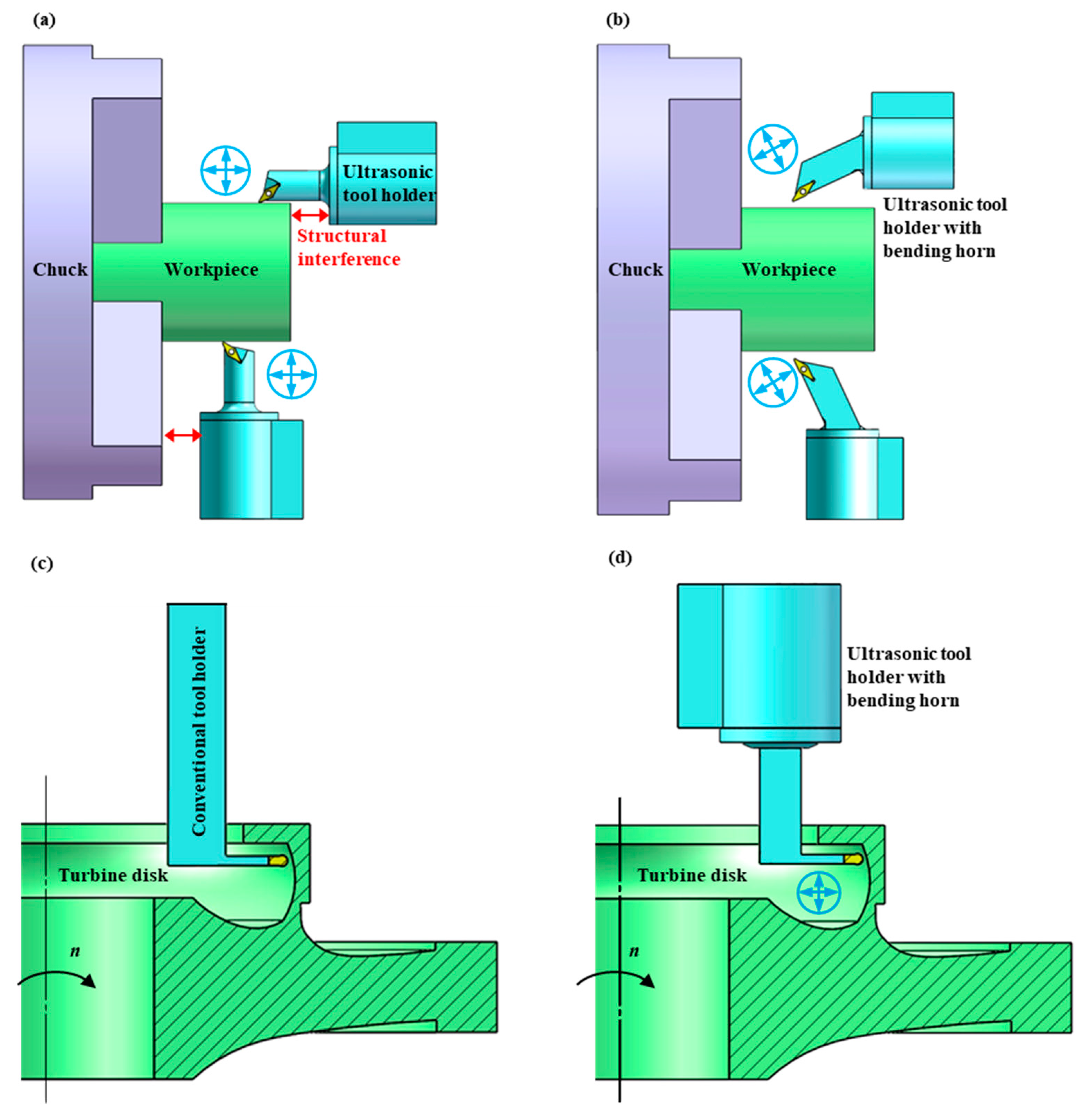
Figure 2.
Schematic diagram of elliptical vibration ultrasonic transducers with bending horn.
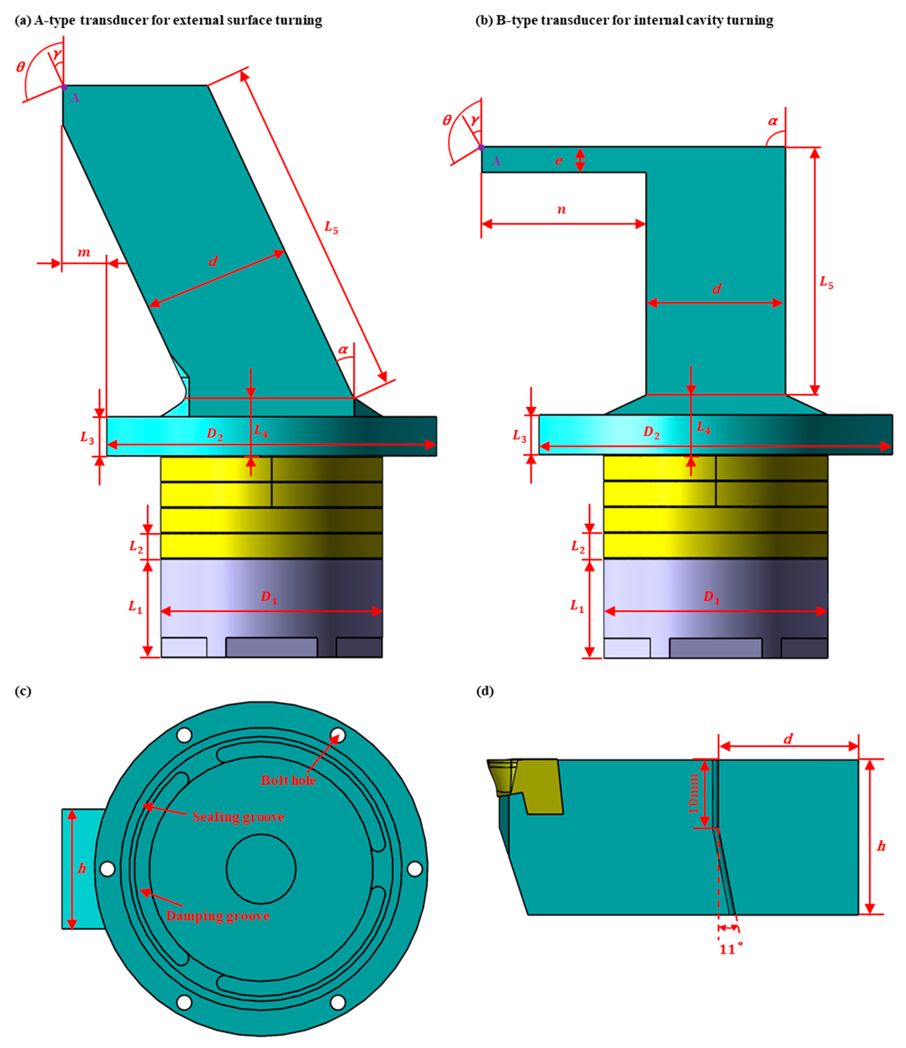
Figure 3.
Flow chart of simulation design for transducer.
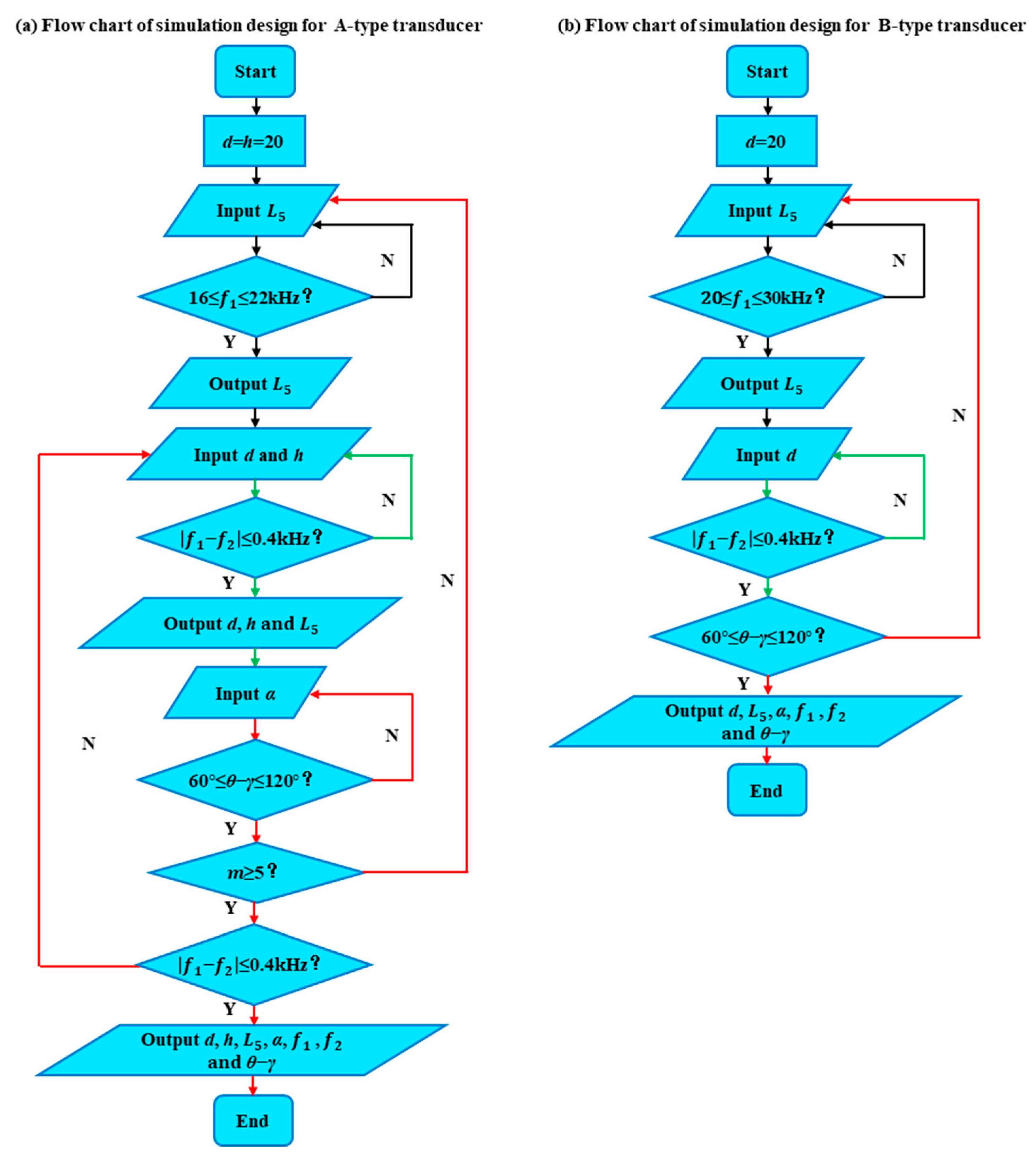
Figure 4.
Influence of structural dimensions of A-type transducer on resonance frequency.
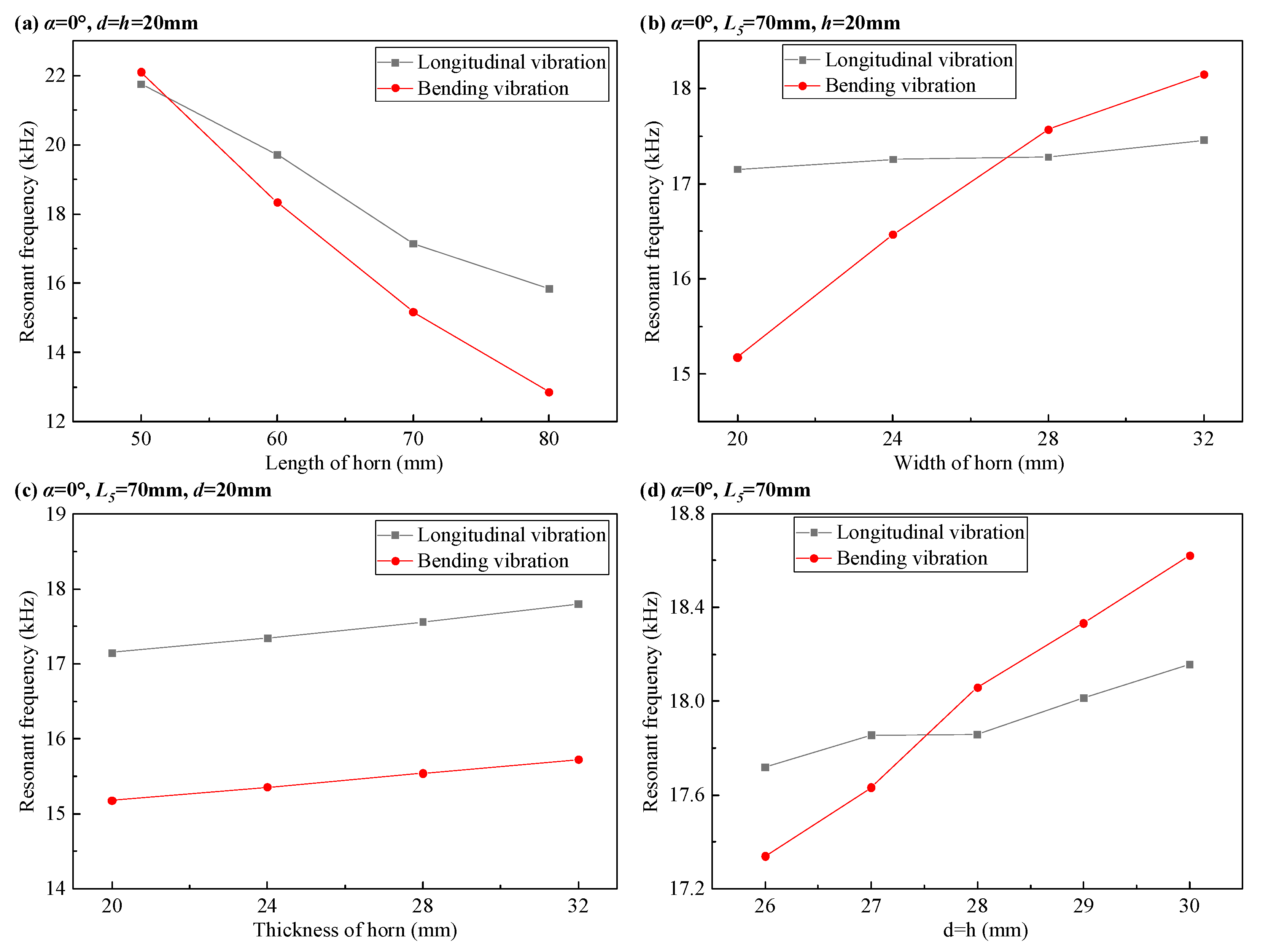
Figure 5.
Influence of α on resonance characteristics in A-type transducer.
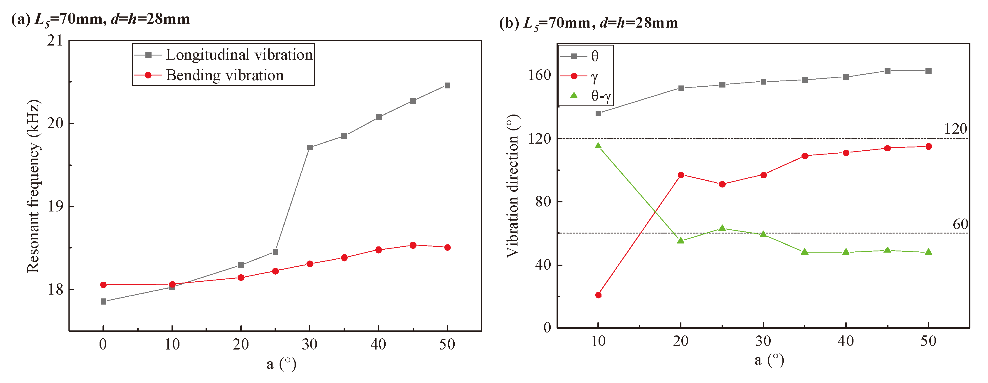
Figure 6.
Influence of structural dimensions of B-type transducer on resonance frequency.
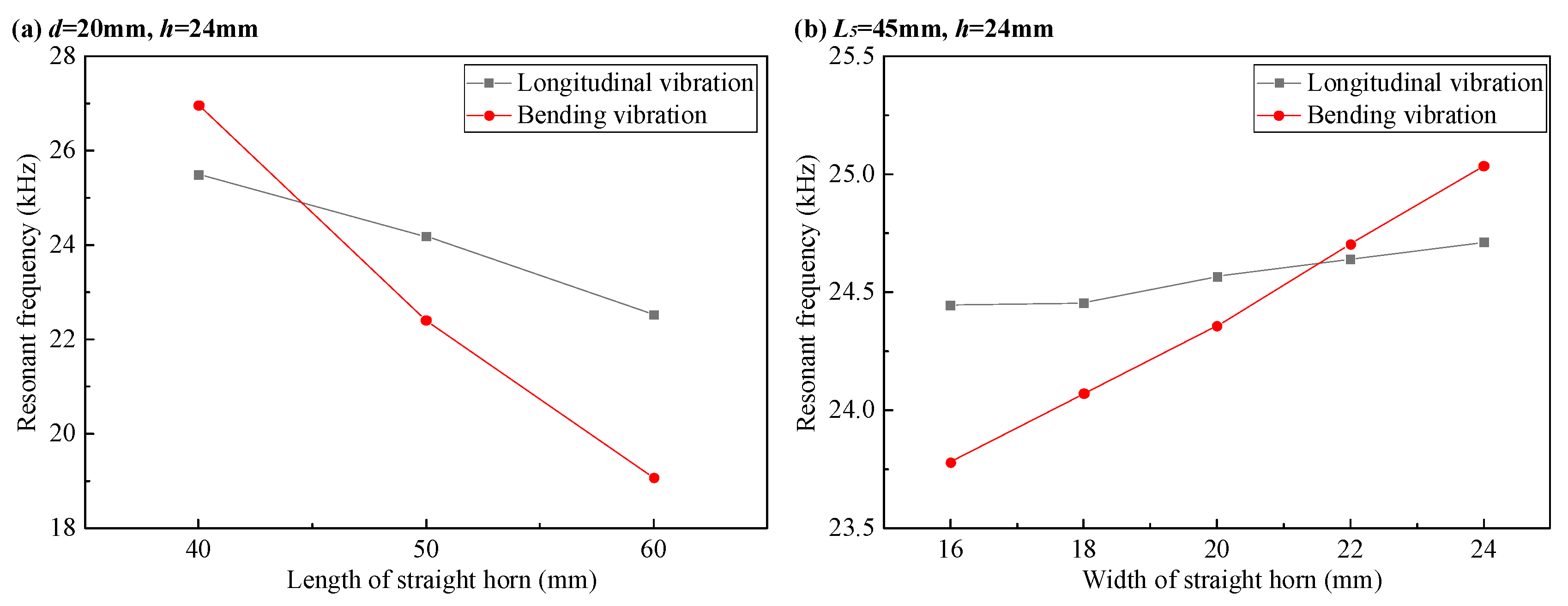
Figure 7.
Modal analysis of the designed transducer.
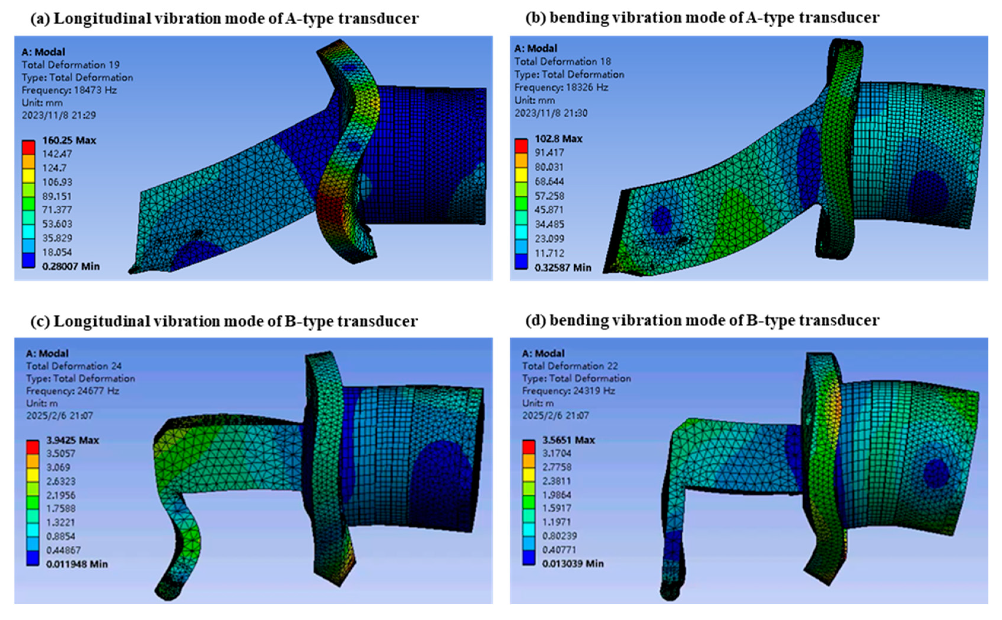
Figure 8.
Measuring device for vibration amplitude and vibration direction.
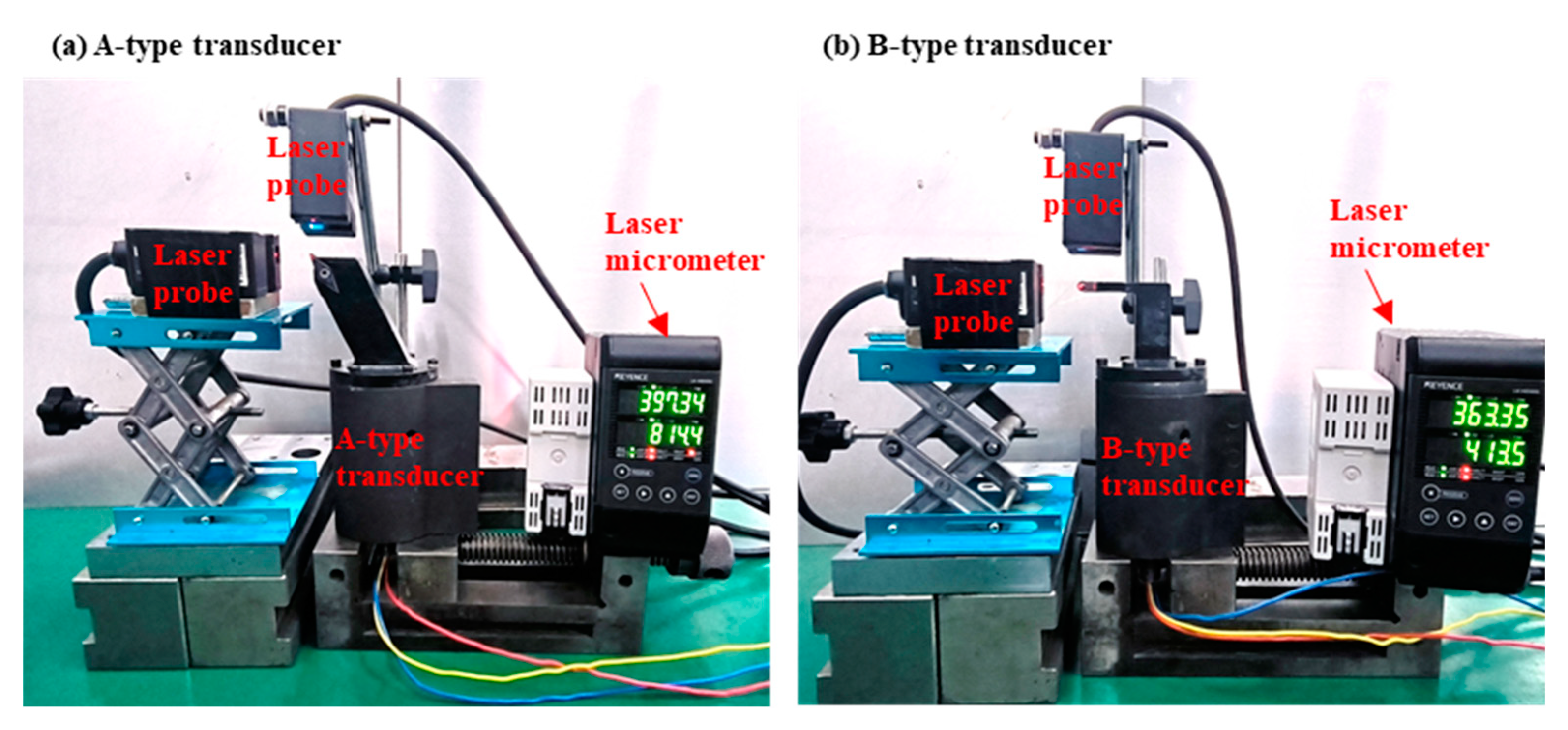
Figure 9.
Peak-peak amplitudes of transducer at different resonant frequencies.
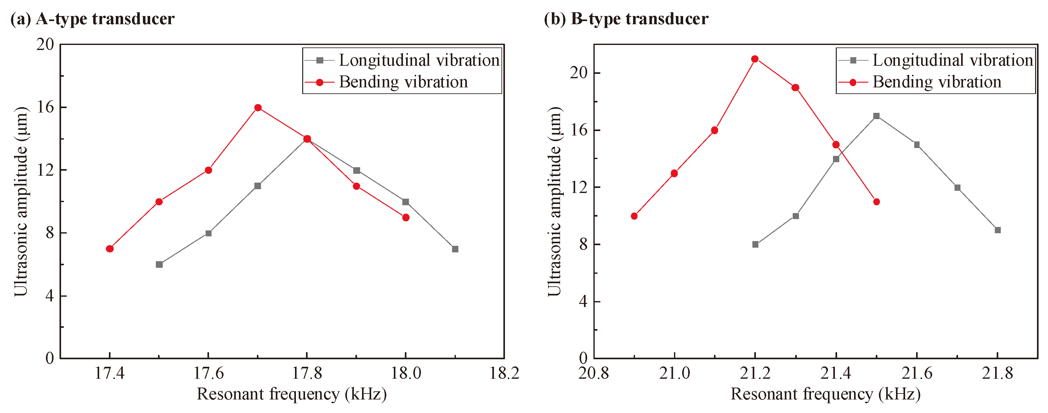
Figure 10.
The vibration trajectories of the tool tip under different phase differences.

Figure 11.
The measured vibration trajectory of the tool tip for A-type transducer at .
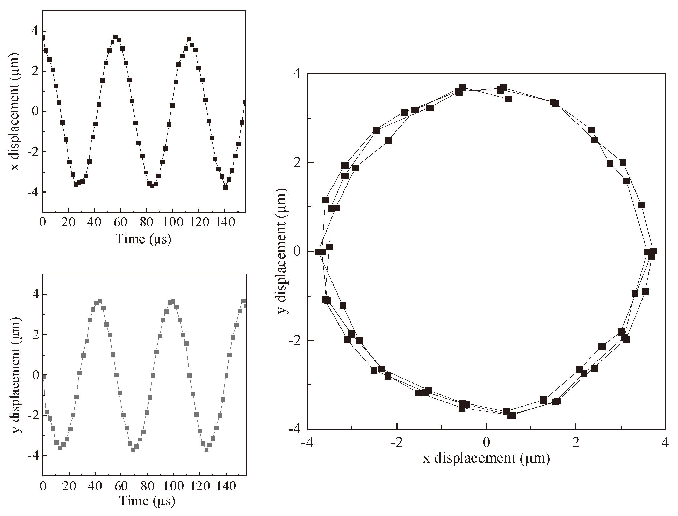
Figure 12.
The measured vibration trajectory of the tool tip for B-type transducer at .
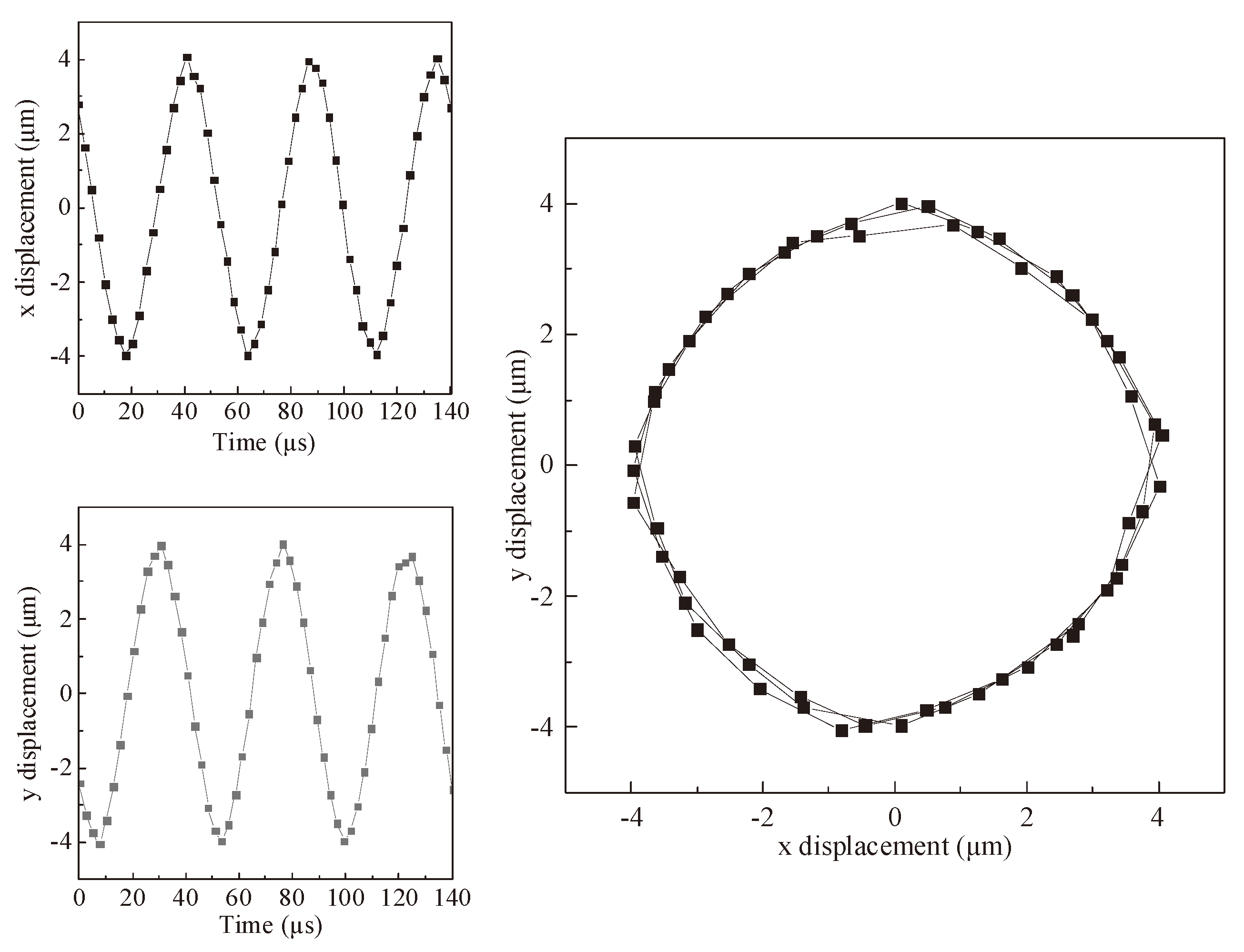
Figure 13.
Experimental setup.
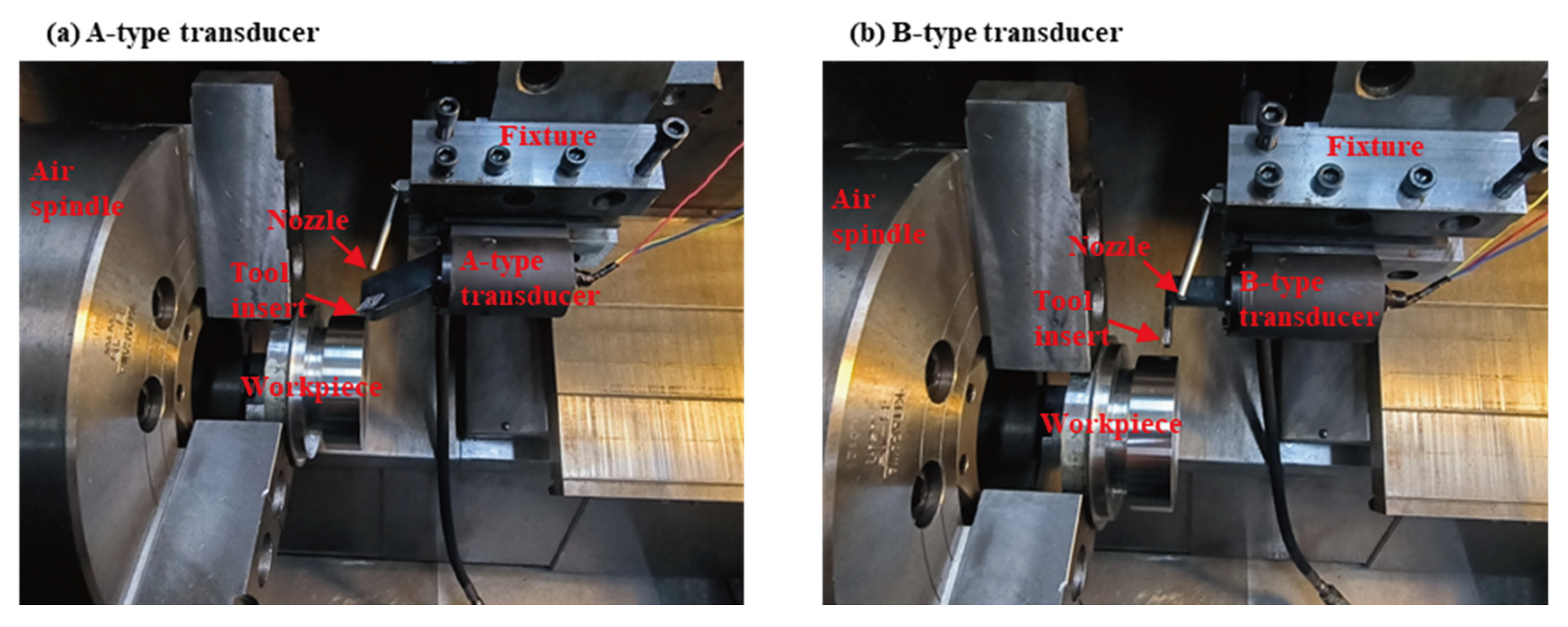
Figure 14.
Effect of cutting distance on flank wear.
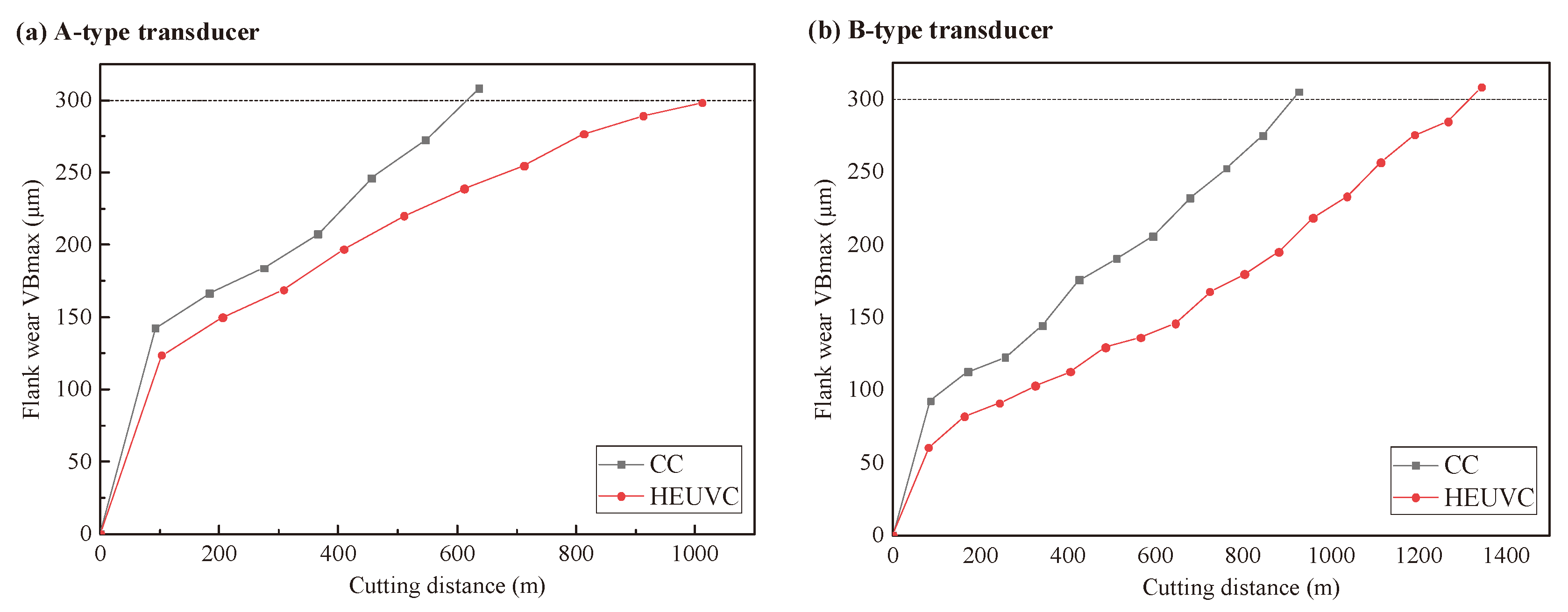
Figure 15.
Topographies of machined surface of Inconel 718.
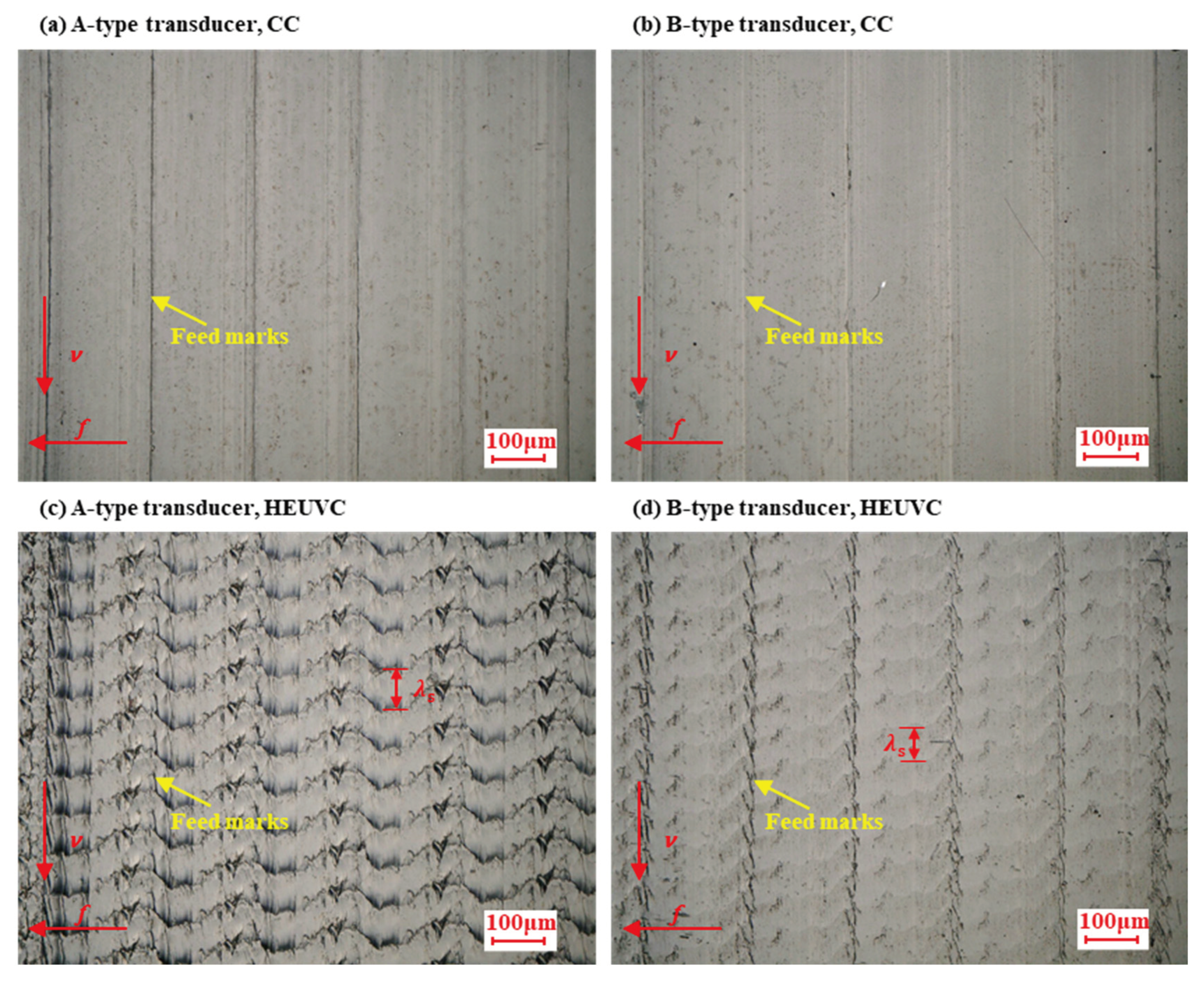

Table 1.
Structural parameters of A-type transducer.
| d | h | m | α | ||||||||||
|---|---|---|---|---|---|---|---|---|---|---|---|---|---|
| 20 | 5 | 8 | 12 | 45 | 71 | ≥5 |
Table 2.
Structural parameters of B-type transducer.
| d | e | h | n | α | ||||||||||
|---|---|---|---|---|---|---|---|---|---|---|---|---|---|---|
| 20 | 5 | 8 | 12 | ≥20 | 45 | 71 | ≤32 | 5.2 | 24 | 34 | 90 |
Table 3.
Material parameters used in finite element simulation.
| Part | Material | Density (kg/m3) | Elastic modulus (GPa) | Poisson ratio |
|---|---|---|---|---|
| Horn | 42CrMo | 7850 | 212 | 0.28 |
| Piezoceramics | PZT-8 | 7600 | 86 | 0.3 |
| Electrode plate | Red copper | 8300 | 110 | 0.34 |
| End cap | AISI 1045 Steel | 7800 | 209 | 0.269 |
| Tool | YT15 | 14000 | 600 | 0.22 |
Table 4.
Structural parameters obtained by simulation for A-type transducer.
| d | h | m | α | ||||||||||
|---|---|---|---|---|---|---|---|---|---|---|---|---|---|
| 20 | 5 | 8 | 12 | 70 | 45 | 71 | 28 | 28 | 6 | 25 | 18.473 | 18.326 | 63 |
Table 5.
Structural parameters obtained by simulation for B-type transducer.
| d | e | h | n | α | ||||||||||
|---|---|---|---|---|---|---|---|---|---|---|---|---|---|---|
| 20 | 5 | 8 | 12 | 43 | 45 | 71 | 20 | 5.2 | 24 | 34 | 90 | 24.677 | 24.319 | 72 |
Table 6.
Machining parameters.
| Parameter type | Parameter (unit) | Value |
|---|---|---|
| Vibration parameters | Vibration frequency (kHz) | 17.8, 21.4 |
| phase difference (°) | 112, 100 | |
| Peak-peak amplitude (μm) | 8 | |
| Process parameters | Cutting speed (m/min) | 80 |
| Depth of cut (mm) | 0.4 | |
| Feed rate (mm/r) | 0.2 | |
| Cooling parameters | Coolant pressure (bar) | 50 |
Disclaimer/Publisher’s Note: The statements, opinions and data contained in all publications are solely those of the individual author(s) and contributor(s) and not of MDPI and/or the editor(s). MDPI and/or the editor(s) disclaim responsibility for any injury to people or property resulting from any ideas, methods, instructions or products referred to in the content. |
© 2025 by the authors. Licensee MDPI, Basel, Switzerland. This article is an open access article distributed under the terms and conditions of the Creative Commons Attribution (CC BY) license (http://creativecommons.org/licenses/by/4.0/).
Copyright: This open access article is published under a Creative Commons CC BY 4.0 license, which permit the free download, distribution, and reuse, provided that the author and preprint are cited in any reuse.


