Submitted:
08 May 2025
Posted:
09 May 2025
You are already at the latest version
Abstract
Protein-coated ultra-high viscosity (UHV)-alginate hydrogels are essential to mimic the physiological in vivo environment for several in vitro applications. This work presents an optimized bioreactor-integrated freeze-drying process of protein-coated UHV-alginate microcarrier in the context of iPSC expansion. The impact of freeze-drying on the UHV-alginate microcarriers using trehalose 100 mg/ml in 0.9% NaCl as a lyoprotective agent, as well as the stem cell response using hiPSCs was analyzed by microscopy-based screenings. First observations of the process showed that the integrity of the cake was preserved in the samples with maximum vapor exchanging rate. After rehydration of the samples, there were no morphological changes of the UHV-alginate microcarriers observed. By addition of Poloxamer 188, the stickiness and bubble formation were reduced. The expansion of iPSC resulted in a 5-7-fold change with a total cell count of at least 1,3x10⁷ cells with viabilities over 80% after seven days cultivation in a suspension bioreactor. The pluripotency factors OCT3/4 and SSEA4 in flow cytometry analysis resulted in positive signals over 98% and less than 10% positive cells for differentiation factor SSEA1. This study presents, for the first time and supported by preceding in silico predictions of drying time, basic steps towards a “ready-to-use” bioreactor-integrated freeze-drying process for UHV-alginate microcarriers in iPSC context.
Keywords:
suspension bioreactor
; drug discovery
; pluripotent stem cells
; freeze-drying
; (UHV)-alginate
; tissue engineering
1. Introduction
Biocompatible biomaterials became indispensable for several applications in biomedical and tissue engineering contexts. As one of the most important representatives of biomaterials, hydrogels are increasing in importance in human stem cell-based applications. These Hydrogels, e.g., ultra-high viscosity (UHV)-alginates are of great interest since they address the unmet need of physiological in vivo environments for in vitro applications [1]. Traditionally, cells, e.g., human induced pluripotent stem cells (hiPSC) are cultivated in planar polystyrene dishes. The cultivation on such plastic surfaces not only limits cell-cell and cell-matrix interactions but limits also the surface’s stiffness and scalability [2,3,4]. Especially the scalability of the growth area is a crucial challenge, since almost all biomedical applications, e.g., cytotoxicity testing and drug screenings, require high cell quantities (>108 cells per application) [5]. To provide high cell quantities, robust and scalable cell expansion processes are needed. A promising tool to facilitate cell expansion is the application of microcarriers in suspension bioreactors (SBR). Microcarriers are spherically shaped and exhibit the highest surface-to-volume ratio [6,7]. Thereby, expansion processes and growth area can easily be scaled up by adding more microcarriers into the SBR without increasing the volume or the number of vessels. Most commercially available microcarriers are either made of stiff polystyrene (e.g., Corning Synthemax®, CytodexTM 1, SoloHill®) or stiffness-undefined dextran-based (CytodexTM 3) (Table 1).
Table 1 shows commercially available cultivation surfaces with different characteristics, clearly demonstrating a lag in “ready-to-use” soft microcarriers. Furthermore, the available microcarriers need further activation and process steps until usage inside a SBR for cell expansion. To overcome this limitation the use of UHV-alginate microcarriers is promising and already established in several hiPSC applications [24]. In particular, UHV-alginate microcarriers were already successfully used for hiPSCs expansion processes [24]. The UHV-alginates used in this study were extracted from brown algae and consist of two 1-4-linked monomers β-D-mannuronic acid (M) and α-L-guluronic acid (G) [25,26,27]. The production of fresh microcarrier for, e.g., hiPSC expansion involves several complex and time-consuming steps. First, alginate sol is added dropwise into a cross-linking solution to create alginate (hydrogel) beads. After the production of alginate beads and cross-linking using Ba2+, the bioinert alginate beads must be functionalized according to Gepp et al. [28]. The UHV-alginate microcarriers are, e.g., protein-coated with Matrigel® (MTG) or collagen I, which enables the cultivation of anchorage-dependent cells, such as stem cells. Afterwards, the modified microcarriers must be stored in an isotonic 0.9% NaCl solution at 4°C. Since the protein-coated UHV-alginate microcarriers are stored in an aqueous solution, several negative side effects occur that influence their physicochemical characteristics, integrity and functionality. During storage of an ionotropic hydrogel in aqueous solution, ions from the hydrogel and the aqueous environment exchange, which directly influences the hydrogel’s physicochemical properties [29,30]. This ion exchange was observed by Saitoh et al. who describes for calcium-alginate hydrogels a release of Ca2+ into the solution and a movement of Na+ from the solution into the hydrogel. This movement results in changes in physicochemical characteristics which influence the cell behavior on the UHV-alginate microcarriers. Another important effect described in literature is the degradation of alginate hydrogels in aqueous solution (e.g., cell culture media). Depending on the molecular weight or chemical modification (e.g., oxidation), the mechanical properties are influenced, as described by Boontheekul et al. [31]. Furthermore, the storage ability of proteins in liquid solutions is limited, since denaturation of the protein layer during storage in liquid solution occurs [32,33,34]. The denaturation of proteins related to cell adhesion cause a loss in functionality and hence, hiPSC cannot attach and spread on the hydrogel surface. In addition, UHV-alginate and MTG are natural products, which exhibit batch-to-batch variation. Aisenbrey et al. describes differences in MTG stiffness, even significant local differences in stiffness within a single batch [35,36]. MTG is a semi-defined protein mixture and its composition varies from batch-to-batch [37]. These properties cannot be influenced or are difficult to influence and lead, in consequence, to lack in reproducibility in cell expansion and cell-matrix interactions understanding. Additionally, UHV-alginate can differ from batch-to-batch e.g., in G/M ratio, which, after further modifications, leads to different mechanical characteristics and rheological behavior [38,39]. To address these challenges and limitations, it is imperative to establish an alternative and improved storage method. The overarching objective is to mitigate both chemical and biological activity, as well as the negative impacts of batch-to-batch variability. Since the adverse effects primarily occur during storage in liquid solutions, implementing a drying method for long-term storage appears to be a sustainable solution. Among various drying techniques, freeze-drying is scalable and noted as the gentlest method for hydrogels [40]. Freeze-drying is a process operated in three steps [41]. In the current state-of-the-art approach, the sample is frozen until total solidification. After solidification, a vacuum is added to the system to remove water by sublimation [42]. The last step includes an increase in temperature to remove unfrozen water by desorption [43]. Using freeze-drying, one UHV-alginate batch and one MTG batch can be processed, modified, freeze-dried for long-term storage and utilized after several months or years. Hereby, batch-to-batch differences are eliminated, and the interpretation of biological data facilitated. In this work, the previously described approach will be further enhanced for applications in stem cells technology and an initial approach towards a “ready-to-use” freeze-dried microcarrier-based SBR process is presented. Protein-coated UHV-alginate microcarrier were freeze-dried directly in the SBR using trehalose as a lyoprotective agent. Freeze-drying directly in the SBR minimizes intermediate steps, thereby reducing the loss of functional cultivation surface. Following the freeze-drying process, functional tests were conducted by expanding hiPSCs on the reconstituted UHV-alginate microcarriers and analyzing cell count as well as the maintenance of their pluripotency status.
2. Results and Discussion
2.1. Simulation of a Modified Freeze-Drying Process for “Ready-to-Use” Alginate Microcarrier Hydrogels
For the implementation of a bioreactor-integrated functional freeze-drying of MTG-coated UHV-alginate microcarriers an initial in silico verification was set up to confirm the effectiveness of the designed process. The average normalized remaining ice content for both the upright (90° oriented) and the tilted (22° oriented) setup is shown in Figure 1.
The contents of the 22° oriented SBR dry significantly faster, reaching 0% ice content after approximately 15.5 h, whereas the 90° oriented SBR retains about 33% after the full 31.5-hour duration. This is attributed to the increased surface area of the frozen solution exposed to the vacuum, leading to higher heat and mass transfer.
2.2. Implementation of a Freeze-Drying Process for “Ready-to-Use” Alginate Microcarrier
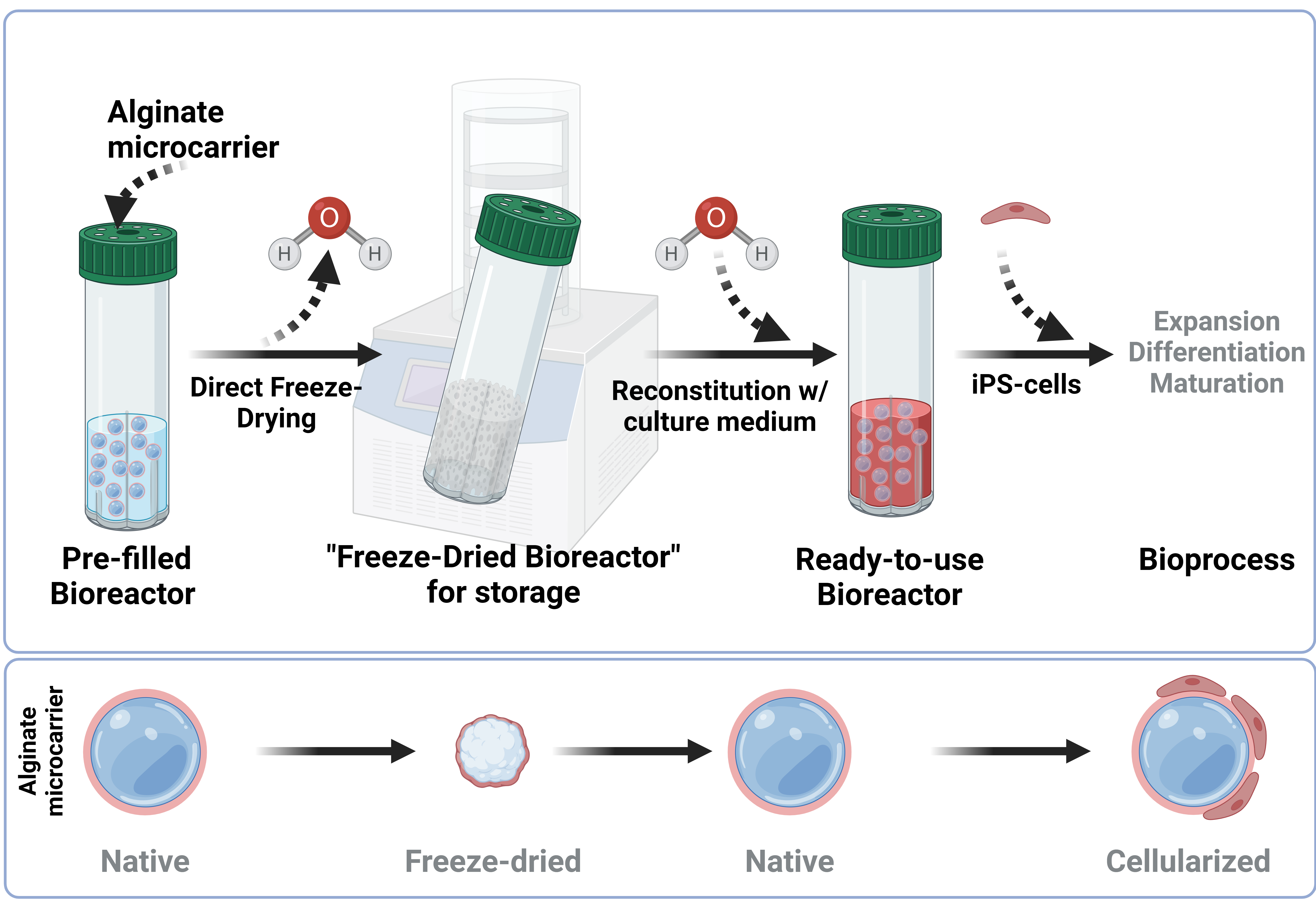
In this study, a bioreactor-integrated freeze-drying process was implemented. Typically, samples are freeze-dried in lyo-vials which requires transferring the sample from the initial tube into the lyo-vial and after freeze-drying into the vessel that is required for the process (Figure 2a). Reducing the transfer steps lead to a decrease of cultivation surface loss and facilitates handling during the process. Figure 2b schematically illustrates the concept of a bioreactor-integrated functional freeze-drying process. The protein-coated UHV-alginate microcarriers along with the lyoprotective agent were directly transferred into the SBR used for the cultivation process (see Figure 2b, steps 1 and 2).
This approach eliminated unnecessary transfer steps and reduced the loss of functional cultivation surface. The conventional freeze-drying process for protein-coated UHV-alginate microcarriers has several bottlenecks and the loss, in worst case, occurs in three situations. The first situation is the loss of microcarriers which stick to the inner wall of the glass vial. Only by time-consuming mechanical and manual “pull-down” support individual microcarrier can be transferred into suspension for further utilization. The second bottle neck are the microcarriers that stick to the bottom edge of the glass vial. By time-consuming resuspending steps, single microcarrier can be collected with the pipette tip. The third bottle neck is the final transferring step from the lyo-vial into the bioreactor. During the transfer from glass vial to SBR, microcarriers can be stuck inside the pipette tip and their further utilization is almost impossible. During the freeze-drying cycle, the SBR was positioned at an angle to accelerate the freezing and drying by increasing the available surface of the solution. Tilting the SBR increases the efficiency of the process. After the cycle, the cakes were rehydrated inside the SBR, the liquid aspirated and the hiPSCs inoculated onto the reconstituted UHV-alginate microcarriers. Since the freeze-drying occurred inside the final vessel, initial steps towards a “ready-to-use” SBR for hiPSCs expansion process have been taken.
2.3. Analysis of Lyophilized Cake Appearance
The appearance of the lyophilized (lyo)-cake is a primary quality indicator following a freeze-drying cycle [44]. Depending on the integrity and shape of the cakes, samples are either accepted or rejected [44]. Collapse or meltback may indicate a loss of product or, at the very least, a decline in product quality and poor process understanding [44]. There are several factors that influence the lyo-cake’s appearance. On one hand, temperature, pressure, and time in correlation with the characteristics of lyoprotective agents influence the lyo-cake appearance; on the other hand, the possibility of vapor escape also influences it. Figure 3 discusses the different vapor escape possibilities.
After freezing the samples, a vacuum is introduced into the chamber of the freeze-dryer to initiate sublimation. During sublimation, water is removed and the water vapor must escape the SBR. Two different possibilities were investigated. In one case, the lid was placed loosely on the SBR, allowing vapor to escape from the edges of the lid (Figure 3a). In the other case, shown in Figure 3b, the lid was closed to prevent escape from the edges. Instead, the membrane was perforated to allow vapor to escape through the lid. Figure 3c-3f illustrated the cake appearances and the influence of the vapor escape possibility. In Figure 3c and 3d, the vapor during sublimation was only able to escape from the edges. Consequently, the lyo-cake exhibited morphological characteristics of collapse (Figure 3c and 3d; dashed circle) and meltback (Figure 3c and 3d; arrows), indicating that sublimation was not complete before initiating secondary drying. After increasing the temperature for secondary drying to 20°C, the lyoprotective agent exceeded both its collapse temperature (tc) (collapse) and ice melting or eutectic point (meltback) leading to a lyo-cake revealing collapse and meltback [44]. According to Patel et al., lyophilized samples exhibiting collapse or meltback are rejected and inappropriate for long-term storage. For aseptic reasons, the primary drying under these conditions could be extended, until all water is removed. In Figure 3e and 3f, vapor exit was enabled by membrane perforation directly through the lid. As seen in the images, homogenous and stable cakes were formed. This cake appearance indicates a complete sublimation cycle. High integrity, uniform and stable lyo-cakes, as seen in Figure 3c and 3d, are important for the product quality, but also for facilitating the rehydration step. Uniform and stable lyo-cakes comparable to Figure 3e and 3f are acceptable according to Patel et al. and suitable for long-term storage. To characterize the suitability for long-term storage, additional properties must be considered, such as residual water content.
2.4. Impact of Poloxamer 188 on the Rehydration
In this section, the addition of Poloxamer 188 (P188) in the formulation was studied. The samples were rehydrated using bidest. water. The impact of P188 is illustrated in Figure 4.
Figure 4a shows the rehydrated samples without P188 in the formulation. The absence of P188 results in significant adsorption of the protein-coated UHV-alginate microcarriers to the inner polystyrene wall of the bioreactor. Furthermore, a high number of bubbles are formed, which hampers the further handling of the process since the bubbles adhere to the microcarriers (Figure 5a and 5b) and do not sediment. Both the bubble formation and the adsorption complicate aspiration of the lyoprotective agent. The addition of P188 facilitates handling. It reduces bubble formation and minimizes the adsorption of the protein-coated UHV-alginate microcarriers to the polystyrene wall of the bioreactor. This enables the aspiration of the lyoprotective agent without further steps. Figure 5c and 5d illustrate the reduction of bubble formation. Furthermore, all conditions result in comparable morphology and structure after freeze-drying and rehydration.
P188 is an amphiphilic surface-active triblock copolymer that exhibits a hydrophobic core and two hydrophilic blocks linked to the core [45,46,47]. The hydrophobic core is capable of adsorbing to hydrophobic surfaces and forming loops by folding. According to Bollenbach et al., the folding creates a hydrophilic surrounding and decreases the hydrophobicity which leads to reduced adsorption of the protein-coated UHV-alginate microcarriers to the polystyrene wall of the bioreactor. As a surface-active detergent, P188 can migrate to interfaces, including air-water interfaces, and reduce the surface tension [48,49]. In Chang et al. it is described for surfactants to decrease cell-bubble-attachment for two reasons: first, it decreases the surface tension of the interface, which leads to an increase of free energy. A cell-bubble interface is formed due to this attachment. When the interface tension decreases, the amount of free energy increases, making cell-bubble attachment less favorable. Furthermore, P188 is noted to reduce the cell’s hydrophobicity. This results in decreased hydrophobic interactions, making it less likely for bubbles to attach to the cell [49]. The same applies to the hydrophobic protein layer of the UHV-alginate microcarriers (Figure 6).
Figure 6 illustrates the functionality of P188. In absence of P188 the hydrophobic layer of MTG interacts with the inner wall of the SBR. This leads to a binding of MTG-coated UHV-alginate microcarrier on the inner wall of SBR. In presence of P188 the hydrophobic core of P188 interacts with MTG and the hydrophilic blocks form a loop which creates a hydrophilic surrounding, thus, preventing the MTG layer from interacting with the inner wall of SBR.
2.5. Cell Count, Cell Viability and Cytometry Analysis
Single cell hiPSCs were inoculated onto the rehydrated protein-coated UHV-alginate microcarriers and the cell response – measured in terms of total cell count, cell viability and pluripotency maintenance – was analyzed after seven days of cell expansion. Figure 7a – 7f shows the different conditions after seven days of cell expansion.
For all conditions for the microcarrier-based expansion (Figure 7a-e), a confluency of 90% can be observed. The confluency for the 2D polystyrene dishes also reaches around 90% (Figure 7f). Figure 8a shows the cell count after harvesting.
In general, the cell yield could be increased around 5-7-fold. 2.4×10⁶ cells were inoculated on the surfaces and yielded in a minimum of around 1.1×10⁷ cells (non-freeze-dried UHV-alginate microcarrier (-FD MC) and a highest of around 2.4×10⁷ cells (2D control). Within the freeze-dried conditions, the cell yield resulted in a minimum of around 1.4×10⁷ (+P188 -P) and a maximum of 1.7×10⁷ cells (-P188 -P). -P188 +P (1.6×10⁷) and +P188 +P (1.5×10⁷) resulted in comparable cell yields. Furthermore, the cell viability within the freeze-dried conditions is comparable in a range of 80-83% living cells (Figure 8b). The highest viability was observed for the 2D control with 93% and the lowest viability was achieved for -FD MC (68% living cells). In Figure 8c-h the flow cytometry analysis shows a similar signal for the pluripotency factors (Oct3/4, SSEA4 & Tra-1-60) and the differentiation factor (SSEA1) in all conditions. The positive signal for Oct3/4 and SSEA4 is between 96% and 99.9%. The positive signal for the differentiation factor SSEA1 varies between <9.8% (-P188 -P) and <4.2% (+P188 -P) indicating a low amount of differentiated hiPSCs. The positive signal for pluripotency factor Tra1-60 is the highest for both controls 2D (51.1%) and -FD MC (50.4%). For the freeze-dried samples it varies between 34.3% (+P188 +P) and 44.1% (-P188 -P). The cell count was increased 5-7-fold in all conditions and the cell viability was minimum 80%. Only in the -FD MC a drop in cell viability was observed which might imply that the expansion processes have to be optimized for each condition. According to the flow cytometry analysis the hiPSCs were able to maintain their pluripotency status. The low positive signal for the pluripotency factor Tra1-60 might be an artefact. During fixation using formaldehyde and storage for more than four weeks, shrinkage of the cells occurs which leads to an inaccessibility for the antibodies to attach to the pluripotency factor. Furthermore, during double staining, the path to the antigen might be blocked. According to the pluripotency and differentiation signals, the hiPSCs could maintain their pluripotency status. Nevertheless, to confirm their pluripotency status differentiation, e.g., trilineage differentiation processes, have to be performed. In total, these findings are promising and next steps for implementing a “ready-to-use” bioreactor-integrated functional freeze-drying for the expansion of iPSCs can be initiated.
3. Conclusions
In this study first investigations towards a “ready-to-use” bioreactor-integrated functional freeze-drying process for protein-coated UHV-alginate microcarriers were performed. Initially, a simple simulation was conducted, demonstrating the shorter primary drying duration of the 22° oriented SBR setup compared to the 90° oriented SBR configuration. However, due to its simplified assumptions, this model cannot predict absolute drying times or optimize process parameters. The freeze-drying process was carried out directly in the SBR. This reduced transferring steps which reduces functional surface loss. The addition of P188 had no negative impact on the morphology or the functionality of the protein-coated UHV-alginate microcarriers. P188 reduced bubble formation and protein adsorption which facilitated the process. The sublimation time for the condition with an intact membrane was not enough to complete water removal before switching to the secondary drying. Due to aseptic reasons, the time could be extended or other possibilities to ensure sterility must be considered. Another important aspect for further investigations is the possibility of completing the freeze-drying process and close the SBR before removing them from the chamber to enable long-term storage under vacuum conditions.
4. Materials and Methods
4.1. In Silico Verification of SBR Orientation During Drying Process
To verify the faster drying rate of the 22° orientation (“ready-to-use”) SBR setup (see Figure 1b), a simple sublimation simulation was set up using the FEM software COMSOL Multiphysics® v6.2 (COMSOL AB, Stockholm, Sweden) on a workstation containing a 16-core 11th Gen Intel® Core™ i9-11900K CPU and 64 GB of RAM. The primary drying processes in the upright (90° orientation) and tilted (22° orientation) SBR setups were compared. The change in normalized remaining ice content is modeled by
where is the initial porosity (dimensionless, representing the fraction of volume occupied by ice). is the density of ice and is the sublimated mass flux per unit volume and time, approximated using the Hertz-Knudsen equation, neglecting secondary mass transfer effects:
Here, T is temperature, is the molar mass of vapor, is the specific surface area, R is the universal gas constant, is an evaporation coefficient, p is the ambient pressure and is the vapor pressure, calculated using an empirical equation (valid for T > 110 K), from Murphy and Koop [50]
The loss in heat due to sublimation is described by
where is the heat of sublimation.
The overall vapor flow and heat transfer were modeled using the “Darcy’s Law” and “Heat Transfer in Solids and Fluids” modules in COMSOL. SBR geometry and solution height were based on laboratory measurements. Drying duration, ambient temperature and pressure are identical to the experimental setup given in Table 1 for primary drying. For simplicity, remaining necessary parameters (e.g., heat capacity, thermal conductivity, density, etc.) were assumed to match pure ice. This assumption is justified, as the model aims to compare drying rates between vial geometries rather than to precisely replicate experimental conditions.
4.2. Cell Culture
The cell line used for the expansion processes was UKBi005-A (BioSample ID: SAMEA4584351, registered on hpscreg.eu), which is an EBiSC hiPSCs cell line. The cells were maintained and cultivated on MTG-coated (Corning, USA) 6 cm cell culture dishes (NunclonTM Delta or Greiner Bio One GmbH) using mTeSRTM1 medium (Stemcell Technologies, Canada). The medium was changed every day, and the cell quality was monitored microscopically. At a confluency of around 80-90% the cells were dissociated with 0.5 mM ethylene-diaminetetraacetic acid (EDTA, Invitrogen, USA) for maintenance. For the single cell expansion processes, the cells were cultivated on 15 cm cell culture dishes (Corning, USA) and dissociated according to section 4.5.
4.3. Hydrogel: UHV-Alginate Microcarrier
One batch of MTG-coated UHV-alginate microcarrier (Alginatec, Germany) was used for the freeze-drying and expansion processes. The alginates were extracted from brown algae Lessonia nigrescens (LN) and Lessonia trabeculata (LT) and modified according to Gepp et al. [28]. A 1:1 (v/v) mixture of the batches LN62 (0.65% solution, solved in 0.9% NaCl) and LT26 (0.65% solution, solved in 0.9% NaCl) were used to produce the microcarrier. The diameter of the microcarrier was about 356 - 370 µm. Per condition, 40 cm2 cultivation surface were used.
4.4. Freeze Drying and Rehydration
40 cm2 MTG-coated UHV-alginate microcarriers were transferred together with 100 mg/ml Trehalose (Trehalose-dihydrate, EMPROVE® EXPERT, Ph. Eur., Sigma Merck) (diluted in 0.9% NaCl (B. Braun)) into the SBR. For the samples without P188 10% (Sigma Merck), the total volume was 16 ml. When P188 was added, the total volume was 17,6 ml resulting in a P188 end concentration of 0.9%. Furthermore, the vessels were positioned inside the freeze-dryer (Alpha 1-4 LSCplus, Martin Christ GmbH, Germany) (see Figure 1b). A trial freeze-drying cycle was conducted by Biopharma Process Systems (Winchester, UK) and further modified (see Table 2). The samples were stored in the freeze-dryer at 20°C and 0.1 mbar until cell availability. After freeze-drying, the samples were rehydrated according to the initial volume (16.0 ml or 17.6 ml) with ddH2O. Samples for microcarrier morphology and bubble formation analysis were taken afterwards and the samples were incubated overnight at 37°C and 5% CO2. The incubation step was followed by centrifugation until the microcarriers were sedimented. Subsequently, the microcarrier were washed 1-2 times with DMEM/F12 -/- (GibcoTM, Thermo Fisher Scientific) before adding single cells for their expansion.
4.5. Dissociation of Single Cells
The hiPSCs were dissociated from the cell culture dishes using TrypLETM (Gibco, USA). First, the cells were washed twice with DMEM -/- or DPBS -/- (GibcoTM, Thermo Fisher Scientific) followed by a 5 min TrypLETM Select (Gibco, USA) dissociation step inside the incubator. The process was stopped by adding mTeSRTM1 to the cell culture dish. After detachment, the cells were centrifuged (3 min, 250g), the supernatant discarded, and the cell pellet resuspended with mTeSRTM1 supplied with 10 µM ROCK Inhibitor Y-27632 to prevent apoptosis of the single cells.
4.6. Cultivation of hiPSCs in a Suspension Bioreactor
The hiPSCs were cultivated in SBRs (CEROtube vessels, OLS, Germany) in a bioreactor system CERO 3D (OLS, Germany) at 37°C and 5% CO2. Starting with the inoculation, 60,000 cells per cm2 were inoculated on the microcarrier. The inoculation volume was around 4.3 ml. The detailed program is listed in Table 3 and was already used in Kwok et al. [24] The volume was filled up to 10 ml after one day and the medium 50% changed every day. Over the weekend, the volume was filled up to 20 ml. The cells were expanded for seven days. To ensure a seven-day expansion process for the cell culture dish control, the cells were split on day 2 or 3 from one dish to two dishes and at day 5 split again on four dishes. The dissociation was performed using EDTA. The cultivation medium included Pen/Strep (1:100, Fisher Scientific). For harvesting, the cells were dissociated with improved EDTA (iEDTA, developed at Fraunhofer IBMT). Before adding the dissociation agent, the cells were washed twice with DPBS -/-. The harvesting step was initiated inside the CERO system for 20 min. When the cells were detached, they were separated from the microcarrier by a 200 µm strainer (pluriSelect Life Science, Germany) followed by a cell count and viability analysis using NucleoCounter® NC-200TM system (ChemoMetec, Denmark). Subsequently, the cells were washed twice with PBS -/- and fixed for 15-20 minutes with 4% formaldehyde (CytofixTM, BD, USA). After fixation, the cells were washed once with staining buffer (BD, USA) and stored in staining buffer at 4°C until further usage.
4.7. Flow Cytometry Analysis
The Human and Mouse Pluripotent Stem Cell Analysis Kit (BD, USA) was used for flow cytometry analysis. Additionally, TRA1-60 (see Table 4) as a further pluripotency factor was used. First, the fixated cells were washed in 5 ml PBS -/-, followed by a two-times washing step in 1 ml Perm/Wash buffer, which was then resuspended in 0.5 ml FACS buffer. Afterwards, the cells got stained with 20 µl antibodies per 1×10⁶ cells for SSEA4, OCT3/4, SSEA1 and 5 µl for TRA1-60 (see Table 4). The stained cells were incubated for 30 minutes at 4°C. After incubation 4 ml FACS buffer was added to the samples and centrifuged for 3 min at 250g. Last, the samples were resuspended in 0.3 ml FACS buffer. Flow cytometry analysis was performed using BD FACS CantoTM II flow cytometer (BD Bioscience).
Author Contributions
Conceptualization, H.Z., J.C.N., M.M.G., M.R. and S.D.; methodology, J.M.B., A.B. and M.M.G; validation, J.M.B., A.B., M.M.G.; formal analysis, J.M.B. and A.B., investigation, J.M.B. and A.B.; resources, H.Z., J.C.N., M.R. and S.D.; data curation, J.M.B. and A.B.; writing—original draft preparation, J.M.B. and A.B.; writing—review and editing, H.Z., J.C.N., M.M.G. M.R. and S.D.; visualization, J.M.B. and A.B.; supervision, H.Z., J.C.N., M.M.G., M.R. and S.D.; project administration, J.C.N., M.R. and S.D.; funding acquisition, J.C.N., H.Z., M.R. and S.D.
Funding
This research was funded by the Bavarian Ministry of Economic Affairs, Regional Development and Energy (to J.C.N) and Fraunhofer Society (to S.D).
Institutional Review Board Statement
Not applicable.
Informed Consent Statement
Not applicable.
Data Availability Statement
The original contributions presented in the study are included in the article, further inquiries can be directed to the corresponding author.
Acknowledgments
The authors thank Andrea Riedmayer (Fraunhofer IBMT) and Bianca Stephan for her technical support with flow cytometry and flow cytometry data analysis.
Conflicts of Interest
The authors declare no conflicts of interest.
References
- Schulz, A.; Gepp, M.M.; Stracke, F.; Briesen, H. von; Neubauer, J.C.; Zimmermann, H. Tyramine-conjugated alginate hydrogels as a platform for bioactive scaffolds. J. Biomed. Mater. Res. A 2019, 107, 114–121. [Google Scholar] [CrossRef]
- Kapałczyńska, M.; Kolenda, T.; Przybyła, W.; Zajączkowska, M.; Teresiak, A.; Filas, V.; Ibbs, M.; Bliźniak, R.; Łuczewski, Ł.; Lamperska, K. 2D and 3D cell cultures - a comparison of different types of cancer cell cultures. Arch. Med. Sci. 2018, 14, 910–919. [Google Scholar] [CrossRef] [PubMed]
- Pampaloni, F.; Reynaud, E.G.; Stelzer, E.H.K. The third dimension bridges the gap between cell culture and live tissue. Nat. Rev. Mol. Cell Biol. 2007, 8, 839–845. [Google Scholar] [CrossRef] [PubMed]
- Jensen, C.; Teng, Y. Is It Time to Start Transitioning From 2D to 3D Cell Culture? AAPS PharmSciTech 2020, 7, 33. [Google Scholar] [CrossRef]
- Bellin, M.; Marchetto, M.C.; Gage, F.H.; Mummery, C.L. Induced pluripotent stem cells: the new patient? Nat. Rev. Mol. Cell Biol. 2012, 13, 713–726. [Google Scholar] [CrossRef] [PubMed]
- Vallabhaneni, H.; Shah, T.; Shah, P.; Hursh, D.A. Suspension culture on microcarriers and as aggregates enables expansion and differentiation of pluripotent stem cells (PSCs). Cytotherapy 2023, 25, 993–1005. [Google Scholar] [CrossRef]
- Badenes, S.M.; Fernandes, T.G.; Rodrigues, C.A.V.; Diogo, M.M.; Cabral, J.M.S. Microcarrier-based platforms for in vitro expansion and differentiation of human pluripotent stem cells in bioreactor culture systems. J. Biotech. 2016, 234, 71–82. [Google Scholar] [CrossRef]
- Steele, J.G.; Dalton, B.A.; Johnson, G.; Underwood, P.A. Polystyrene chemistry affects vitronectin activity: an explanation for cell attachment to tissue culture polystyrene but not to unmodified polystyrene. J. Biomed. Mater. Res. 1993, 27, 927–940. [Google Scholar] [CrossRef]
- Zeiger, A.S.; Hinton, B.; van Vliet, K.J. Why the dish makes a difference: quantitative comparison of polystyrene culture surfaces. Acta Biomater. 2013, 9, 7354–7361. [Google Scholar] [CrossRef]
- Acevedo-Acevedo, S.; Crone, W.C. Substrate stiffness effect and chromosome missegregation in hIPS cells. J. Negat. Results Biomed. 2015, 14, 22. [Google Scholar] [CrossRef]
- Strale, P.-O.; Azioune, A.; Bugnicourt, G.; Lecomte, Y.; Chahid, M.; Studer, V. Multiprotein Printing by Light-Induced Molecular Adsorption. Adv. Mater. 2016, 28, 2024–2029. [Google Scholar] [CrossRef] [PubMed]
- Ho, K.K.Y.; Buschhaus, J.M.; Zhang, A.; Cutter, A.C.; Humphries, B.; Luker, G.D. Substrate stiffness regulates triple-negative breast cancer signaling through CXCR4 receptor dynamics. bioRxiv 2025. [CrossRef]
- Visonà, A.; Cavalaglio, S.; Labau, S.; Soulan, S.; Joisten, H.; Berger, F.; Dieny, B.; Morel, R.; Nicolas, A. Substrate softness increases magnetic microdiscs-induced cytotoxicity. Nanoscale Adv. 2024, 7, 219–230. [Google Scholar] [CrossRef]
- van Wezel, A.L. Growth of cell-strains and primary cells on micro-carriers in homogeneous culture. Nature 1967, 216, 64–65. [Google Scholar] [CrossRef]
- Chen, X.-Y.; Chen, J.-Y.; Tong, X.-M.; Mei, J.-G.; Chen, Y.-F.; Mou, X.-Z. Recent advances in the use of microcarriers for cell cultures and their ex vivo and in vivo applications. Biotechnol. Lett. 2020, 42, 1–10. [Google Scholar] [CrossRef] [PubMed]
- Sart, S.; Agathos, S.N.; Li, Y. Engineering stem cell fate with biochemical and biomechanical properties of microcarriers. Biotechnol. Prog. 2013, 29, 1354–1366. [Google Scholar] [CrossRef]
- Spearman, M.; Rodriguez, J.; Huzel, N.; Butler, M. Production and glycosylation of recombinant beta-interferon in suspension and cytopore microcarrier cultures of CHO cells. Biotechnol. Prog. 2005, 21, 31–39. [Google Scholar] [CrossRef]
- Li, B.; Wang, X.; Wang, Y.; Gou, W.; Yuan, X.; Peng, J.; Guo, Q.; Lu, S. Past, present, and future of microcarrier-based tissue engineering. J. Orthop. Translat. 2015, 3, 51–57. [Google Scholar] [CrossRef] [PubMed]
- Tavassoli, H.; Alhosseini, S.N.; Tay, A.; Chan, P.P.Y.; Weng Oh, S.K.; Warkiani, M.E. Large-scale production of stem cells utilizing microcarriers: A biomaterials engineering perspective from academic research to commercialized products. Biomaterials 2018, 181, 333–346. [Google Scholar] [CrossRef]
- Rafiq, Q.A.; Coopman, K.; Nienow, A.W.; Hewitt, C.J. Systematic microcarrier screening and agitated culture conditions improves human mesenchymal stem cell yield in bioreactors. Biotechnol. J. 2016, 11, 473–486. [Google Scholar] [CrossRef]
- Simão, V.A.; Brand, H.; Da Silveira-Antunes, R.N.; Fukasawa, J.T.; Leme, J.; Tonso, A.; Ribeiro-Paes, J.T. Adipose-derived stem cells (ASCs) culture in spinner flask: improving the parameters of culture in a microcarrier-based system. Biotechnol. Lett. 2023, 45, 823–846. [Google Scholar] [CrossRef] [PubMed]
- Yuan, Y.; Kallos, M.S.; Hunter, C.; Sen, A. Improved expansion of human bone marrow-derived mesenchymal stem cells in microcarrier-based suspension culture. J. Tissue Eng. Regen. Med. 2014, 8, 210–225. [Google Scholar] [CrossRef] [PubMed]
- Larsson, A.P.; Briheim, K.; Hanna, V.; Gustafsson, K.; Starkenberg, A.; Vintertun, H.N.; Kratz, G.; Junker, J.P.E. Transplantation of autologous cells and porous gelatin microcarriers to promote wound healing. Burns 2021, 47, 601–610. [Google Scholar] [CrossRef]
- Kwok, C.K.; Sébastien, I.; Hariharan, K.; Meiser, I.; Wihan, J.; Altmaier, S.; Karnatz, I.; Bauer, D.; Fischer, B.; Feile, A.; et al. Scalable expansion of iPSC and their derivatives across multiple lineages. Reprod. Toxicol. 2022, 112, 23–35. [Google Scholar] [CrossRef]
- Storz, H.; Müller, K.J.; Ehrhart, F.; Gómez, I.; Shirley, S.G.; Gessner, P.; Zimmermann, G.; Weyand, E.; Sukhorukov, V.L.; Forst, T.; et al. Physicochemical features of ultra-high viscosity alginates. Carbohydr. Res. 2009, 344, 985–995. [Google Scholar] [CrossRef] [PubMed]
- Storz, H.; Zimmermann, U.; Zimmermann, H.; Kulicke, W.-M. Viscoelastic properties of ultra-high viscosity alginates. Rheol. Acta 2010, 49, 155–167. [Google Scholar] [CrossRef]
- Zimmermann, H.; Shirley, S.G.; Zimmermann, U. Alginate-based encapsulation of cells: past, present, and future. Curr. Diab. Rep. 2007, 7, 314–320. [Google Scholar] [CrossRef]
- Gepp, M.M.; Fischer, B.; Schulz, A.; Dobringer, J.; Gentile, L.; Vásquez, J.A.; Neubauer, J.C.; Zimmermann, H. Bioactive surfaces from seaweed-derived alginates for the cultivation of human stem cells. J. Appl. Phycol. 2017, 29, 2451–2461. [Google Scholar] [CrossRef]
- Dodero, A.; Pianella, L.; Vicini, S.; Alloisio, M.; Ottonelli, M.; Castellano, M. Alginate-based hydrogels prepared via ionic gelation: An experimental design approach to predict the crosslinking degree. Eur. Polym. J. 2019, 118, 586–594. [Google Scholar] [CrossRef]
- Saitoh, S.; Araki, Y.; Kon, R.; Katsura, H.; Taira, M. Swelling/deswelling mechanism of calcium alginate gel in aqueous solutions. Dent. Mater. J. 2000, 19, 396–404. [Google Scholar] [CrossRef]
- Boontheekul, T.; Kong, H.-J.; Mooney, D.J. Controlling alginate gel degradation utilizing partial oxidation and bimodal molecular weight distribution. Biomater. 2005, 26, 2455–2465. [Google Scholar] [CrossRef]
- Chang, L.L.; Pikal, M.J. Mechanisms of protein stabilization in the solid state. J. Pharm. Sci. 2009, 98, 2886–2908. [Google Scholar] [CrossRef]
- Mensink, M.A.; Frijlink, H.W.; van der Voort Maarschalk, K.; Hinrichs, W.L.J. How sugars protect proteins in the solid state and during drying (review): Mechanisms of stabilization in relation to stress conditions. Eur. J. Pharm. Biopharm. 2017, 114, 288–295. [Google Scholar] [CrossRef] [PubMed]
- Pardeshi, S.R.; Deshmukh, N.S.; Telange, D.R.; Nangare, S.N.; Sonar, Y.Y.; Lakade, S.H.; Harde, M.T.; Pardeshi, C.V.; Gholap, A.; Deshmukh, P.K.; et al. Process development and quality attributes for the freeze-drying process in pharmaceuticals, biopharmaceuticals and nanomedicine delivery: a state-of-the-art review. Futur. J. Pharm. Sci. 2023, 9. [Google Scholar] [CrossRef]
- Soofi, S.S.; Last, J.A.; Liliensiek, S.J.; Nealey, P.F.; Murphy, C.J. The elastic modulus of Matrigel as determined by atomic force microscopy. J. Struct. Biol. 2009, 167, 216–219. [Google Scholar] [CrossRef]
- Aisenbrey, E.A.; Murphy, W.L. Synthetic alternatives to Matrigel. Nat. Rev. Mater. 2020, 5, 539–551. [Google Scholar] [CrossRef] [PubMed]
- Talbot, N.C.; Caperna, T.J. Proteome array identification of bioactive soluble proteins/peptides in Matrigel: relevance to stem cell responses. Cytotechnology 2015, 67, 873–883. [Google Scholar] [CrossRef] [PubMed]
- Diebels, S.; Gepp, M.M.; Meiser, I.; Roland, M.; Stracke, F.; Zimmermann, H. A multiphase model for the cross-linking of ultra-high viscous alginate hydrogels. Proc. Appl. Math. Mech. 2021, 20. [Google Scholar] [CrossRef]
- Fu, S.; Buckner, I.S.; Block, L.H. Inter-grade and inter-batch variability of sodium alginate used in alginate-based matrix tablets. AAPS PharmSciTech 2014, 15, 1228–1237. [Google Scholar] [CrossRef]
- Smaniotto, F.; Prosapio, V.; Zafeiri, I.; Spyropoulos, F. Freeze drying and rehydration of alginate fluid gels. Food Hydrocoll. 2020, 99, 105352. [Google Scholar] [CrossRef]
- Merivaara, A.; Zini, J.; Koivunotko, E.; Valkonen, S.; Korhonen, O.; Fernandes, F.M.; Yliperttula, M. Preservation of biomaterials and cells by freeze-drying: Change of paradigm. J. Control. Release 2021, 336, 480–498. [Google Scholar] [CrossRef] [PubMed]
- Odziomek, K.; Drabczyk, A.K.; Kościelniak, P.; Konieczny, P.; Barczewski, M.; Bialik-Wąs, K. The Role of Freeze-Drying as a Multifunctional Process in Improving the Properties of Hydrogels for Medical Use. Pharmaceuticals 2024, 17. [Google Scholar] [CrossRef] [PubMed]
- Pansare, S.K.; Patel, S.M. Lyophilization Process Design and Development: A Single-Step Drying Approach. J. Pharm. Sci. 2019, 108, 1423–1433. [Google Scholar] [CrossRef]
- Patel, S.M.; Nail, S.L.; Pikal, M.J.; Geidobler, R.; Winter, G.; Hawe, A.; Davagnino, J.; Rambhatla Gupta, S. Lyophilized Drug Product Cake Appearance: What Is Acceptable? J. Pharm. Sci. 2017, 106, 1706–1721. [Google Scholar] [CrossRef]
- Torcello-Gómez, A.; Wulff-Pérez, M.; Gálvez-Ruiz, M.J.; Martín-Rodríguez, A.; Cabrerizo-Vílchez, M.; Maldonado-Valderrama, J. Block copolymers at interfaces: interactions with physiological media. Adv. Colloid Interface Sci. 2014, 206, 414–427. [Google Scholar] [CrossRef] [PubMed]
- Bollenbach, L.; Buske, J.; Mäder, K.; Garidel, P. Poloxamer 188 as surfactant in biological formulations - An alternative for polysorbate 20/80? Int. J. Pharm. 2022, 620, 121706. [Google Scholar] [CrossRef] [PubMed]
- Yakaew, S.; Luangpradikun, K.; Phimnuan, P.; Nuengchamnong, N.; Kamonsutthipaijit, N.; Rugmai, S.; Nakyai, W.; Ross, S.; Ungsurungsei, M.; Viyoch, J.; et al. Investigation into poloxamer 188-based cubosomes as a polymeric carrier for poor water-soluble actives. J. Appl. Polym. Sci. 2022, 139. [Google Scholar] [CrossRef]
- Peng, H.; Ali, A.; Lanan, M.; Hughes, E.; Wiltberger, K.; Guan, B.; Prajapati, S.; Hu, W. Mechanism investigation for poloxamer 188 raw material variation in cell culture. Biotechnol. Prog. 2016, 32, 767–775. [Google Scholar] [CrossRef]
- Chang, D.; Fox, R.; Hicks, E.; Ferguson, R.; Chang, K.; Osborne, D.; Hu, W.; Velev, O.D. Investigation of interfacial properties of pure and mixed poloxamers for surfactant-mediated shear protection of mammalian cells. Colloids Surf. B Biointerfaces 2017, 156, 358–365. [Google Scholar] [CrossRef]
- Murphy, D.M.; Koop, T. Review of the vapour pressures of ice and supercooled water for atmospheric applications. Q. J. R. Meteorol. Soc. 2005, 131, 1539–1565. [Google Scholar] [CrossRef]
Figure 1.
Simulation of two different setups with simplified SBR 90° upright to the shelf (a) and 22° tilted to the shelf (b). The simulation shows a significant faster water removal for the 22° oriented SBR (c). The average remaining ice for the 22° oriented SBR reaches zero after approximately 15.5 h.
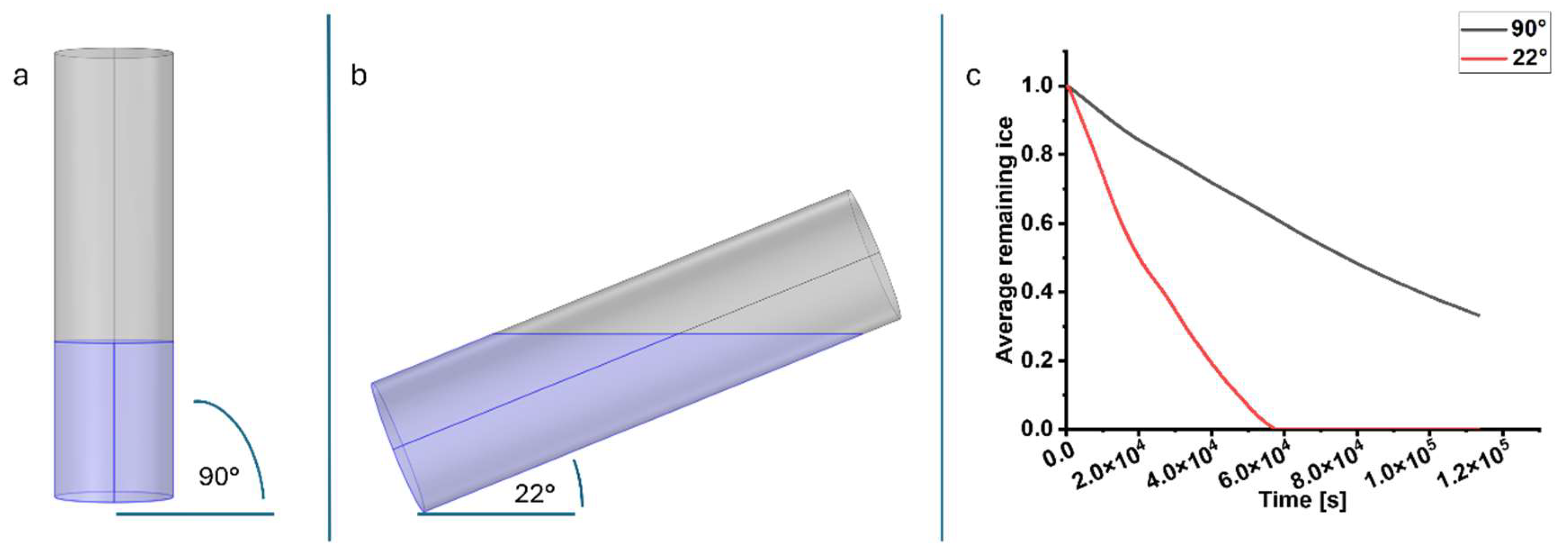
Figure 2.
Freeze-drying strategies. (a) State-of-the-art freeze-drying cycle from loading to cell inoculation. The UHV-alginate microcarriers must be transferred from the initial tube into the lyo-vial along with the lyoprotective agent. The sample, together with the lyoprotective agent, is then transferred to the freeze-dryer where the freeze-drying cycle (FDC) can be initiated. After the cycle, the sample must be rehydrated and transferred to the vessel required for the experiment. (b) Freeze-drying cycle for read-to-use microcarriers in a bioreactor. The UHV-alginate microcarriers are stored in a 0.9% isotonic NaCl solution (1) and are poured together with the lyoprotective agent formulation directly into the SBR that is intended for the cultivation process (2). The SBRs were positioned at an angle in the freeze-dryer to maximize the surface area and accelerate the process (3). Subsequently, the freeze-drying process is initiated until the samples were dried (4). Afterwards, the dried samples are rehydrated and the solution was aspirated (5). In the final step (6), the iPSCs are inoculated onto the rehydrated UHV-alginate microcarriers. Figure created with BioRender.com.
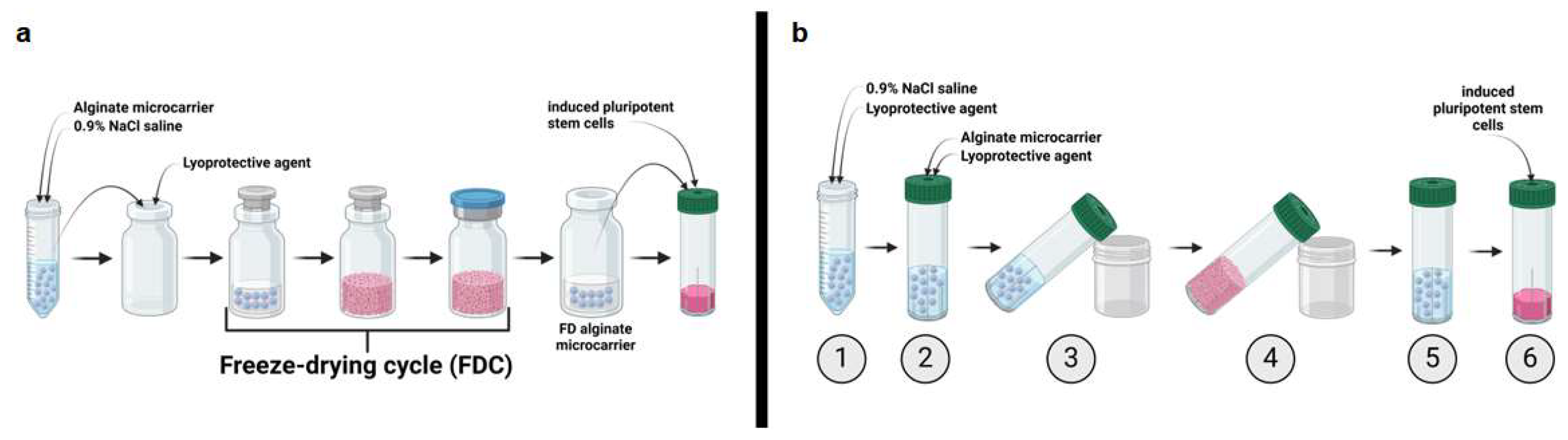
Figure 3.
Schematic illustration of Sublimation systems and Cake appearances. Water vapor escaping possibilities during sublimation. (a) the lid was not totally closed to enable escaping possibilities between the lid and bioreactor. The membrane therefore was left closed. (b) the lid was closed properly to prevent the exit of the vapor on the interspace. Instead, the membrane was perforated to enable vapor exit through the lid. Figure created with BioRender.com. Different cake appearances depending on the water vapor escaping possibilities. When the membrane remains closed and vapor is exclusively escaping through the interspace, the lyo-cake reveals two morphological characteristics: collapse (dashed circle) and meltback (arrows) ((a) and (b)). When the exit is occurring through the perforated membrane, the cakes form a uniform cake with high integrity ((e) and (f)).
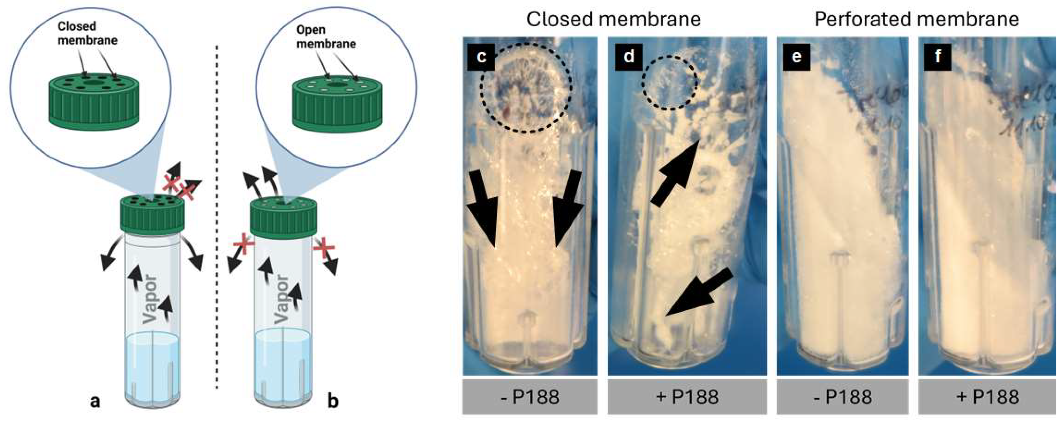
Figure 4.
Rehydration of the cakes and impact of P188 addition on the rehydration. When P188 is not added to the formulation (a) bubble formation occurs. Furthermore, the UHV-alginate microcarriers stick to the inner wall of the SBR. By addition of P188, bubble formation as well as the stickiness of the UHV-alginate microcarriers were reduced (b). Arrow in (a) indicate sticky UHV-alginate microcarriers.
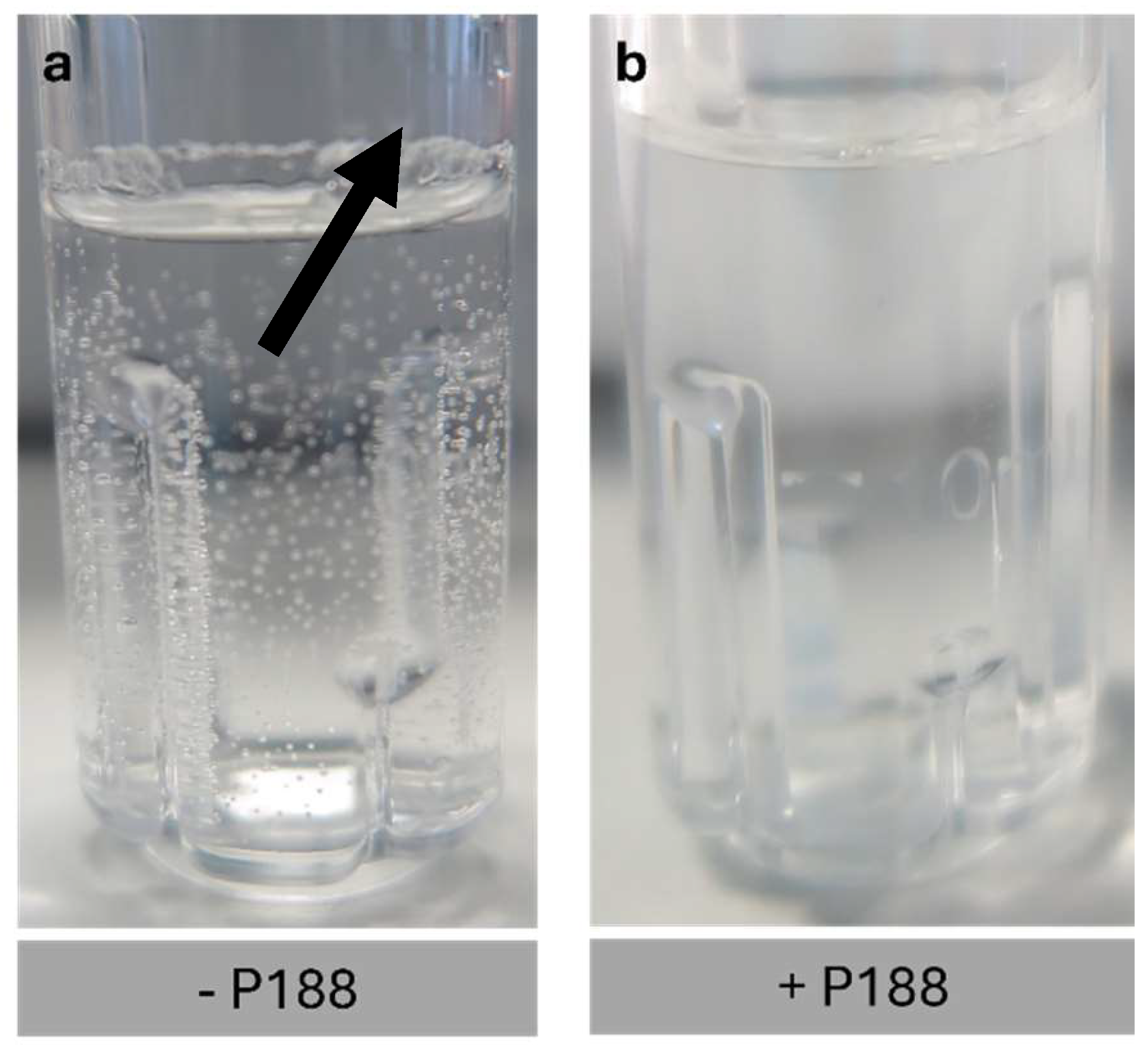
Figure 5.
Microscopy-based analysis of the rehydrated UHV-alginate microcarriers. In absence of P188 bubbles were formed ((a) and (b)). The black dots represent a bubble (arrows). By adding P188 to the formulation bubble formation was reduced (c) and (d). Scalebar: 200 µm.
Figure 5.
Microscopy-based analysis of the rehydrated UHV-alginate microcarriers. In absence of P188 bubbles were formed ((a) and (b)). The black dots represent a bubble (arrows). By adding P188 to the formulation bubble formation was reduced (c) and (d). Scalebar: 200 µm.
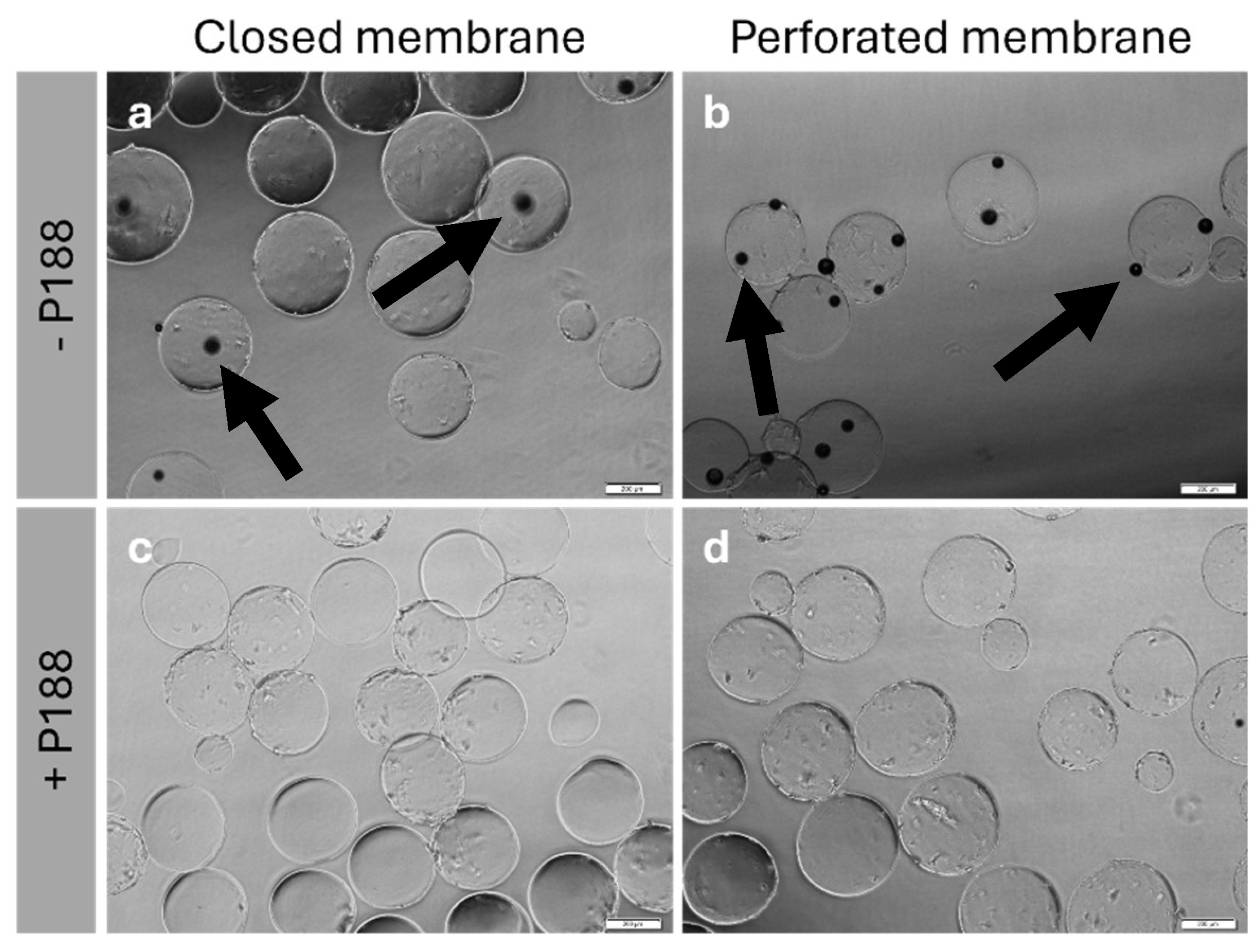
Figure 6.
Effect of P188 on reduction of stickiness. After rehydration of the MTG-coated UHV-alginate microcarriers the hydrophobic protein layer interacts in absence of P188 with the inner wall of the SBR resulting in a significant amount of microcarrier being adhesive on the wall (left side). In P188 presence, the hydrophobic center is interacting with the hydrophobic layer of MTG. The hydrophilic blocks of P188 form a loop and thereby seal the hydrophobic MTG and prevent the proteins to interact with the inner wall of the SBR (right side). Figure created with BioRender.com.
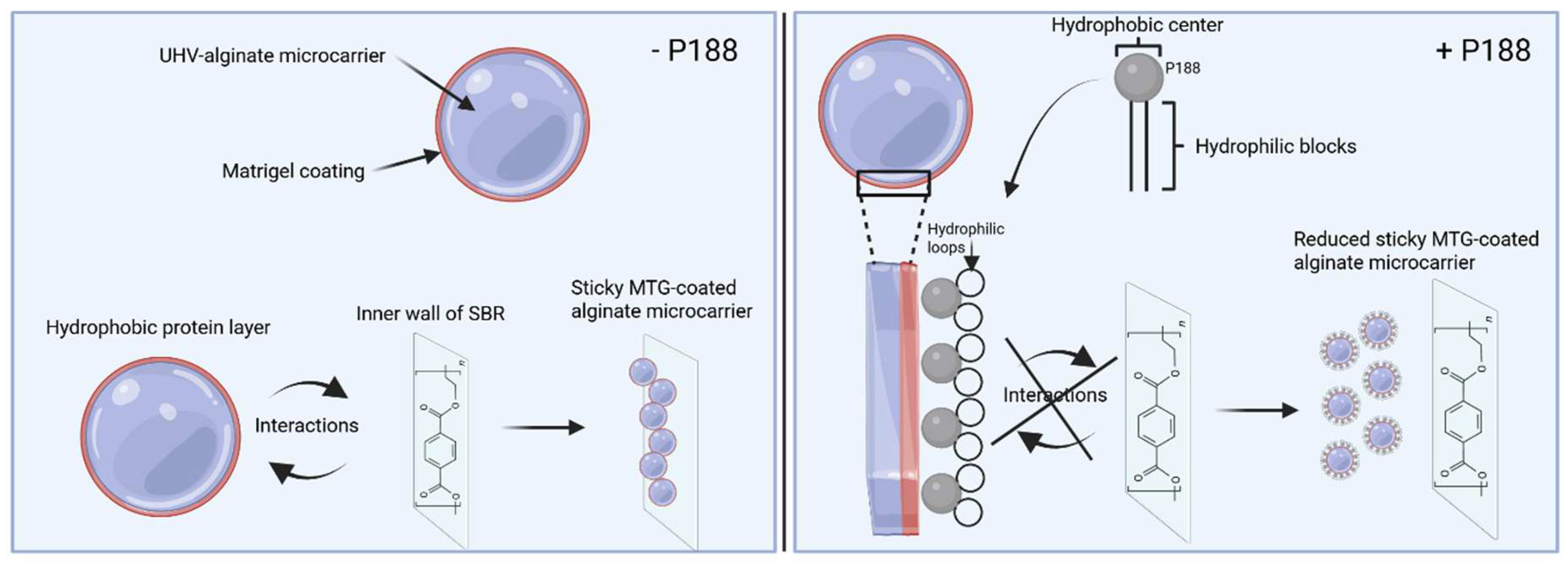
Figure 7.
Validation of the functionality of freeze-dried and rehydrated UHV-alginate microcarriers by inoculating iPSC’s and analyzing adhesion and proliferation. The images (a) – (d) show hiPSCs cultivated for seven days on rehydrated UHV-alginate microcarriers. (e) shows hiPSCs cultivated on non-freeze-dried UHV-alginate microcarriers. In (f), the iPSC’s were cultivated for seven days on a control polystyrene dish. Scale bar = 200µm.
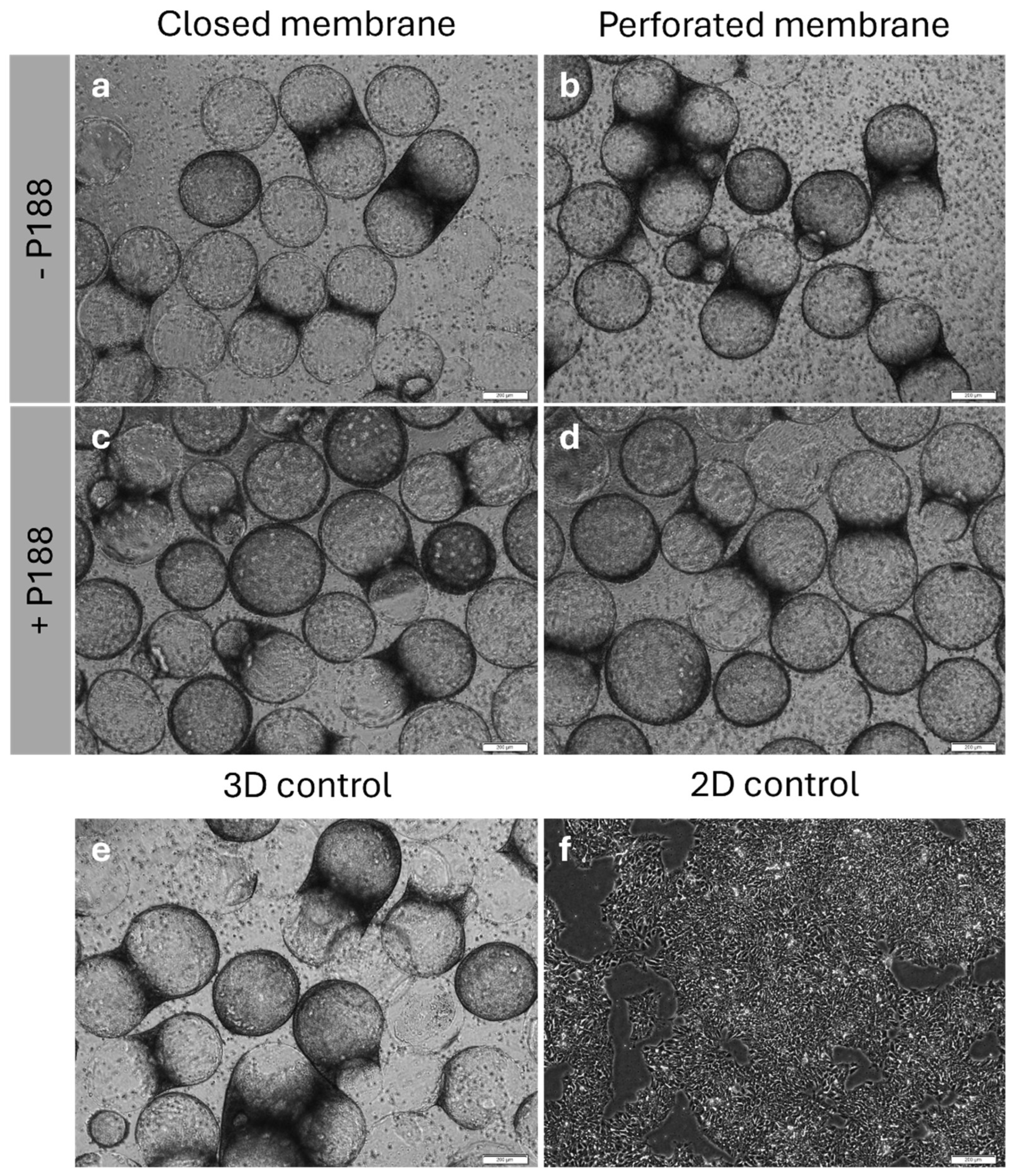
Figure 8.
Quality control of hiPSCs after expansion on freeze-dried microcarriers. Cell count (a), viability (b) and pluripotency (c-h) of the iPSC’s after seven cultivation days. 2.4×10⁶ cells were inoculated on 40 cm2 UHV-alginate microcarriers and were compared to the state-of-the-art cultivation on polystyrene dish (2D control). Flow cytometry for pluripotency analysis was performed using three pluripotency factors (OCT3/4, SSEA4, TRA 1-60) and one differentiation factor (SSEA1). Positive detected cells were determined for the condition closed membrane with P188 (-P188 -P) (c), perforated membrane without P188 (-P188 +P) (d), closed membrane with P188 (+P188 -P) (e), perforated membrane with P188 (+P188 +P) (f), non-freeze-dried UHV-alginate microcarrier (-FD MC) (g) and the 2D control (h). Data are represented as means ± s.d. of n=4 (cell count and viability) and n=3 (pluripotency) independent experiments.
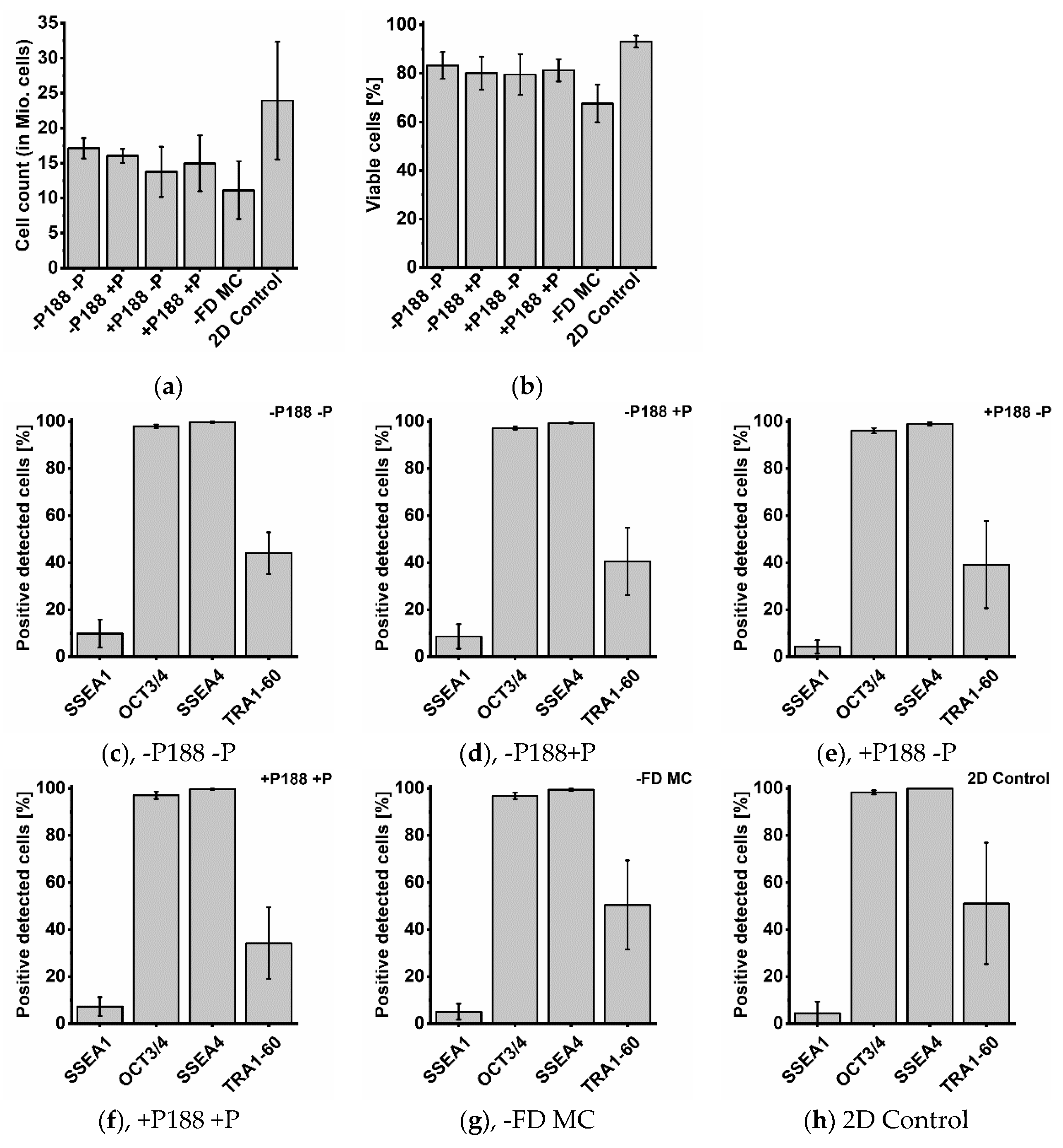

Table 1.
Overview of commercially available cultivation surfaces with different dimensions, materials and stiffnesses. Although the table highlights representative examples, it should not be considered a comprehensive listing of all “ready-to-use” cell culture surfaces presently available commercially.
| Brand name | Manufacturer or Reference | Dimension | Type | Material | Stiffness |
| NuncTM | Thermo Fisher Scientific, [8,9] | Flat | Wellplates, culture dishes, flasks | Polystyrene (Nunclon delta) | 2.28-3.28 GPa [10] |
| Elastically Supported Surface (ESS) | Ibidi, [11,12] | Flat | Culture dishes | Polydimethylsiloxane (PDMS) with glass bottom | 1.5, 15. 28 kPa |
| SoftwellTM, Petrisoft, Softslip, Soft Flask | Matrigen, https://store.matrigen.com | flat | Wellplates, culture dishes, flasks | Polyacrylamide-based gel bound on polystyrene or glass | 0.1-100 kPa |
| CytoSoft® | Advanced BIOMATRIX, https://advancedbiomatrix.com/cytosoft/ | Flat | Wellplates, flasks | PDMS (with glass bottom) | 0.2-64 kPa |
| MecaChips® | Cell&Soft, [13] | Flat | Culture dishes, wellplates | ECM Proteins or synthetic amino acid | 1-25 kPa |
| CytodexTM 1 | Cytiva, [14,15] | Sphere | Microcarrier | Diethylaminoethyl (DEAE)-groups coupled on Dextran | n.d. |
| CytodexTM 3 | Cytiva, [15,16] | Sphere | Microcarrier | Denaturated collagen coated on dextran | n.d. |
| CytoporeTM 1 | Cytiva, [15,17] | Sphere | Microcarrier | DEAE-groups coupled on cellulose | n.d. |
| Solohill® | Sartorius, [18,19] | Sphere | Microcarrier | (Modified or cross-linked) polystyrene & available with (surface modified) Type 1 porcine collagen coating | n.d. |
| Corning® Microcarrier | Corning, [20] | Sphere | Microcarrier | Polystyrene coated with e.g., Synthemax II® | n.d. |
| Dissolvable microcarriers | IamFluidics & Rousselot Biomedical, https://iamfluidics.com/products/dissolvable-microcarriers/ | Sphere | Dissolvable microcarrier | Sodium alginate coated with denaturated collagen | n.d. |
| CultiSpher®: G, GL, S | Percell Biolytica, [21,22,23] | Sphere | Microcarrier | Gelatine | n.d. |
Table 2.
Process parameters for the freeze-drying cycles of UHV-alginate microcarriers.
| Parameter | Ramp | Hold | Ramp | Hold | Ramp | Hold |
| Temperature [°C] | Maximum | Maximum | Maximum | Maximum | 20 | 20 |
| Pressure [mbar] | / | / | 0.05 | 0.05 | 0.1 | 0.1 |
| Time [h] | 2.5 | 12 | 1.5 | 30 | 5 | ≥8 |
| Event | Freezing | Freezing | Primary drying | Primary drying | Secondary drying | Secondary drying |
Table 3.
Program for dynamic expansion processes of single cell hiPSCs in CERO SBRs. Program was previously used in Kwok et al.
Table 3.
Program for dynamic expansion processes of single cell hiPSCs in CERO SBRs. Program was previously used in Kwok et al.
| Program | Rotation period [s] | Rotation speed [rpm] | Agitation period [min] | Agitation pause [min] | Duration |
| Inoculation | 4 | 40 | 2 | 5 | 12 h |
| Cultivation | 4 | 40 | 2 | / | 7 days |
| Harvesting | 5 | 60 | / | / | 20 min |
Table 4.
Pluripotency and differentiation antibodies and isotype controls used for flow cytometry analysis.
Table 4.
Pluripotency and differentiation antibodies and isotype controls used for flow cytometry analysis.
| Antibodies | Dilution |
| Alexa Fluor® 647 Rat anti-SSEA4 Alexa 647 Mouse IgG3, K Isotype Control |
20 µl per million cells |
| PerCP-CyTM 5.5 Mouse anti-OCT3/4 PerCP-CyTM 5.5 Mouse IgG1, K Isotype Control |
20 µl per million cells |
| PE Rat anti-SSEA1 PE Mouse IgM, K Isotype Control |
20 µl per million cells |
| Alexa Fluor® 488 anti-human TRA1-60 Alexa 488 Mouse IgM, K Isotype Control |
5 µl per million cells |
Disclaimer/Publisher’s Note: The statements, opinions and data contained in all publications are solely those of the individual author(s) and contributor(s) and not of MDPI and/or the editor(s). MDPI and/or the editor(s) disclaim responsibility for any injury to people or property resulting from any ideas, methods, instructions or products referred to in the content. |
© 2025 by the authors. Licensee MDPI, Basel, Switzerland. This article is an open access article distributed under the terms and conditions of the Creative Commons Attribution (CC BY) license (http://creativecommons.org/licenses/by/4.0/).
Copyright: This open access article is published under a Creative Commons CC BY 4.0 license, which permit the free download, distribution, and reuse, provided that the author and preprint are cited in any reuse.


