
Submitted:
08 May 2025
Posted:
09 May 2025
You are already at the latest version
Abstract
In pipe jacking construction, thixotropic slurry critically governs lubrication, friction reduction, and ground support. This study evaluated slurry performance through six parameters: specific gravity (SG), pH, fluid loss (FL), water separation rate (WSR), filter cake thickness (FCT), and funnel viscosity (FV). Orthogonal experiments optimizing bentonite, carboxymethyl cellulose (CMC), and sodium carbonate (Na₂CO₃) ratios established 10 wt.% bentonite, 0.4 wt.% CMC, and 0.3 wt.% Na₂CO₃ as the optimal formulation. Subsequently, to address performance limitations in challenging conditions, this study introduces hydroxyethyl cellulose (HEC) as a novel additive, with potential advantages under high-salinity and variable pH conditions. Comparative experiments demonstrated that HEC, as a non-ionic water-soluble cellulose, not only significantly increases FV and reduces FL while maintaining SG, FCT, and WSR within acceptable thresholds, but also exhibits superior pH stability compared to CMC. The microstructures of the three thixotropic slurries with distinct compositions were examined using scanning electron microscopy (SEM) based on the aforementioned results, leading to systematic analysis of their structural characteristics and friction-reduction mechanisms that microscopically demonstrated the good compatibility between HEC and bentonite.These findings highlight HEC’s potential as an effective alternative in pipe jacking, particularly in demanding geological environments.
Keywords:
pipe jacking construction
; thixotropic slurry mix design
; orthogonal experiment
; hydroxyethyl cellulose
1. Introduction
Pipe jacking technology, as an advanced trenchless technology for underground pipeline installation, has seen extensive application in urban utility networks and major infrastructure projects—including transport tunnels, hydraulic systems, and utility corridors—due to its minimal surface disruption and ecological benefits [1,2]. The technique operates by hydraulically or mechanically thrusting prefabricated pipe segments through the ground while excavating the tunnel face. Nevertheless, substantial technical challenges persist, particularly with interfacial friction between pipes and surrounding strata. As projects encounter longer distances, larger diameters [3,4,5,6,7,8] or complex geologies [9,10,11,12,13,14,15], frictional resistance exhibits nonlinear escalation. This not only demands higher jacking forces but also risks construction defects (e.g., pipe misalignment) and geohazards (e.g., ground settlement), especially in high-water-table or soft-soil conditions. In practical engineering, various engineering measures have been adopted to reduce the jacking force, such as grouting with thixotropic slurry and installation of intermediate jacking stations[16,17].
The thixotropic slurry friction-reduction technique addresses this challenge by forming interfacial lubricating films. Injection of the slurry into the pipe-strata annular gap establishes a stable lubricating layer that significantly reduces friction coefficients and enhances jacking performance - with formulation quality being the primary determinant of effectiveness [18,19,20,21,22]. Conventional thixotropic slurries typically contain bentonite, carboxymethyl cellulose (CMC), sodium carbonate (Na₂CO₃), and water. As the key thickening agent, CMC enables stable lubricating film formation through its combined shear-thinning behavior and water retention capabilities.
Recent research on thixotropic slurry technology for complex geological applications has evolved along two parallel tracks: performance enhancement through multicomponent additives and the development of environmentally sustainable formulations. Microbial-induced calcium carbonate precipitation (MICP) technology has emerged as a particularly promising approach, demonstrating the ability to simultaneously reduce interfacial friction coefficients and reinforce adjacent strata through bacterially-mediated calcification processes [23]. In parallel, boronic acid-crosslinked polymer systems have been successfully incorporated into polyacrylamide-bentonite slurries, effectively addressing the biodegradation limitations characteristic of conventional materials [24]. The strategic combination of plant-derived additives (gums and potassium humate) with synthetic components (sodium carboxymethyl cellulose and graphite powder) has yielded measurable improvements in overall slurry performance [8] , while nanomaterial additives have shown particular efficacy in enhancing both thixotropic behavior and rheological properties [17]. Furthermore, the technological synergy with drilling fluid systems, which share fundamental compositional and functional characteristics with thixotropic slurries, has generated several significant innovations, including core-shell nano acrylic resin/SiO₂ composites for enhanced wellbore stability in shale gas applications [25],laponite nanoparticles for improved thermal stability [26], and specialized cellulose derivatives for precise rheological modification [27].
In addition, cellulose ether modification research [28,29,30,31] offers new avenues for slurry enhancement. Hydroxyethyl cellulose (HEC), sharing water-soluble cellulose ether characteristics with CMC, demonstrates superior thickening, water retention, and rheological performance [27,32,33,34,35,36,37], with established applications in food [38], pharmaceuticals [39,40], 3D printing, and oilfields. Compared to CMC, HEC's non-ionic nature confers enhanced acid stability and salt tolerance, particularly advantageous in pH-fluctuating or high-salinity strata. These attributes position HEC as a promising candidate for thixotropic slurry optimization in geologically challenging environments.
While HEC has demonstrated efficacy in conventional drilling fluids, its performance in pipe jacking slurry applications remains insufficiently characterized. This study first employed orthogonal experimental design to systematically investigate bentonite-CMC-Na2CO3 formulations, quantitatively determining the hierarchical influence of constituent components. Subsequently, through the innovative incorporation of HEC as a novel thickener, comparative experiments revealed HEC’s exceptional capability in enhancing thixotropic slurry performance metrics. Microstructural characterization via scanning electron microscopy (SEM) was conducted on three distinct formulations—bentonite-CMC- Na2CO3, bentonite-CMC, and bentonite-HEC—to elucidate structural configurations and their correlation with drag reduction mechanisms. This paper establishes a new technical pathway for slurry material optimization, offering both theoretical significance and engineering application potential.
2. Materials and Methods
2.1. Materials and Slurry Preparation
Figure 1 displays the four materials used in the thixotropic slurry, whose complete specifications are provided in Table 1.
This study established standardized preparation procedures for the following two distinct formulation systems.
For the Na₂CO₃-containing system, preparation commenced with precise weighing of components according to formulated ratios. The standardized protocol consisted of four consecutive stages: (i) 2-minute dry blending of bentonite and CMC, (ii) incremental addition of 5% Na₂CO₃ solution in three aliquots with continuous 3-minute mixing, (iii) incorporation of remaining water accompanied by 5-minute wet mixing, and (iv) final 24-hour temperature-controlled hydration in sealed containers.
For the Na₂CO₃-free system, preparation commenced with precision weighing of bentonite and selected cellulose (CMC or HEC), progressing through sequential phases: (i) initial 2-minute dry mixing of bentonite with selected cellulose (CMC or HEC), (ii) transfer to mixing tank and subsequent 8-minute aqueous mixing for complete dispersion, (iii) application of the identical temperature-controlled curing protocol as the Na₂CO₃ system, and (iv) concluding 24-hour sealed hydration phase.
All specimens were prepared in triplicate (n=3). Experimental data underwent outlier removal via Grubbs' criterion prior to calculating arithmetic means as final results.
2.2. Experimental Methods
This study developed a comprehensive performance evaluation system based on six critical parameters: specific gravity, Marsh funnel viscosity, pH, fluid loss, filter cake thickness, water separation rate, and Marsh funnel viscosity. The detailed experimental methods are as follows: Specific gravity (SG) determined using an NB-1 mud balance (Figure 2a); Marsh funnel viscosity (FV) measured with standardized Marsh funnels (Figure 2b); pH value measured by PHB-4 portable pH meters (Figure 2c); Fluid loss (FL) and filter cake thickness (FCT) assessed via ZNS-2A filter press (Figure 2d,Figure 2e); Water separation rate (WSR), quantified using a 1000 mL graduated cylinder (Figure 2f) after 24 h static sedimentation.
2.3. Experimental Design
2.3.1. Orthogonal Experimental Design and Range Analysis
Orthogonal experimental design is an efficient, rapid, and economical methodology for investigating multi-factor and multi-level systems. In this study, an orthogonal design was employed to examine the synergistic effects of sodium bentonite content, CMC concentration, and Na₂CO₃ dosage on slurry performance. Based on the multi-factor, multi-level orthogonal design principle, a three-factor, four-level orthogonal array (L₁₆(4³)) was implemented to systematically analyze the interaction mechanisms among these components [17]. The experimental factor-level configuration is presented in Table 2.
The experimental results were analyzed using the range analysis method [41]. Range analysis determines the influence intensity of factors by calculating the average values (K) of the corresponding indicators at different levels of each factor. The range value (R = Kₘₐₓ - Kₘᵢₙ) is used to assess the significance of each factor: a larger range indicates a more significant influence of the factor on the performance indicator. The ranking of range values determines the primary and secondary relationships among factors, guiding the optimization direction of the formulation.
2.3.2. Comparative Experimental Design
Building upon the orthogonal experimental investigation of CMC's influence on thixotropic slurry performance, this study established a binary control system to systematically evaluate the feasibility of substituting CMC with HEC as the thickening agent. The experimental design incorporated parallel formulations: an experimental group combining 8 wt.% sodium bentonite with HEC (0.2–1.0 wt.%) and a control group maintaining 8 wt.% sodium bentonite with CMC (0.2–1.0 wt.%) for direct performance comparison.
The detailed mix proportion parameters for each group are presented in Table 3. Through systematic comparative analysis of the effects of HEC and CMC on key slurry performance indicators—including SG, pH, FL, WSR, FCT, and FV—this study evaluates the performance enhancement effects of HEC across varying dosage gradients (0.2–1.0 wt.%) relative to CMC. This analysis aims to demonstrate the potential application of HEC in thixotropic slurry systems.
Figure 3 details the workflow of orthogonal experiments and comparative experiments, along with the slurry preparation procedures.
2.4. SEM Microstructural Observation
The microstructural characteristics of three slurry systems—bentonite-CMC-Na₂CO₃, bentonite-CMC, and bentonite-HEC—were systematically investigated using a Hitachi SU3500 field-emission scanning electron microscope (Figure 4). Sample preparation involved oven-drying at 55°C for 6 hours to constant weight, followed by ion-sputter gold coating to ensure adequate conductivity. High-resolution imaging was conducted in secondary electron imaging (SEI) mode at progressively increasing magnifications of 400× for macrostructural evaluation, 1500× for interfacial characterization, and 3000× for microstructural examination.
4. Results and Discussion
4.1. Analysis of Orthogonal Experimental Results
The orthogonal experimental results are presented in Table 4. Based on the experimental data, the mean (K) and range (R) for each influencing factor were calculated to quantify their impacts on the thixotropic slurry performance. Through range analysis, the factors were then ranked by significance, and the optimal combination within the three-factor concentration range was determined.
The contribution effects of three factors on FL are illustrated in Figure 5, where the four level values of each factor are represented on the x-axis and the FL values are indicated on the y-axis. The analysis results demonstrate that the degree of influence of each factor on slurry FL follows the order: CMC > bentonite > Na2CO3. Specifically, FL shows a significant decreasing trend with increasing CMC and bentonite content, while it initially decreases and then increases with rising Na2CO3 content. The range analysis in Table 5 further confirms this conclusion, with the range values ranking as: CMC (R=4.275) > bentonite (R=2.3) > Na2CO3 (R=0.775). Notably, FL exhibits a negative correlation with slurry performance, meaning that lower FL corresponds to better slurry performance. Therefore, when optimizing the slurry formulation, priority should be given to increasing the dosage of CMC and bentonite, while the Na2CO3 content needs to be controlled within an optimal range to achieve the best slurry performance. Ultimately, the optimal combination for minimizing slurry fluid loss was determined to be A₄B₄C₃.
The contribution effects of three factors on FV are illustrated in Figure 6, where the four level values of each factor are represented on the x-axis and the FV values are indicated on the y-axis.The analysis results reveal that the degree of influence of each factor on slurry FV follows the order: bentonite > CMC > Na₂CO₃. Specifically, FV shows a significant increasing trend with rising bentonite and CMC content, while it exhibits a clear decreasing trend with increasing Na₂CO₃ content. The range analysis in Table 6 further confirms this conclusion, with the range values ranking as: bentonite (R=343.75) > CMC (R=215.5) > Na₂CO₃ (R=213). Notably, bentonite demonstrates the most pronounced effect on FV enhancement, as evidenced by its significantly higher range value compared to other factors, indicating its dominant role in regulating slurry viscosity. Although CMC and Na₂CO₃ show relatively smaller effects, their influence remains non-negligible. Ultimately, the A₃B₂C₃ formulation was identified as the optimal composition for maintaining slurry FV within the target range of 100-120 s, achieving balanced rheological properties and stability.
The contribution effects of three factors on FCT are illustrated in Figure 7, where the four level values of each factor are represented on the x-axis and the FCT values are indicated on the y-axis.The analysis results demonstrate that the degree of influence of each factor on FCT follows the order: bentonite > CMC > Na₂CO₃. Specifically, FCT shows a significant increasing trend with rising bentonite content, while it exhibits a fluctuating pattern of initial decrease followed by increase with increasing CMC content. For Na₂CO₃, the FCT displays a more complex trend of increase, decrease, and subsequent increase. The range analysis in Table 7 further confirms this conclusion, with the range values ranking as: bentonite (R=0.55) > CMC (R=0.275) > Na₂CO₃ (R=0.2). The range values indicate that bentonite has the most pronounced effect on FCT, with its range value approximately twice that of CMC and 2.75 times that of Na₂CO₃, highlighting its dominant role in regulating FCT. Although both CMC and Na₂CO₃ exhibit relatively minor overall effects, their complex variation trends suggest potentially significant impacts on FCT within specific concentration ranges. Ultimately, through comprehensive analysis of optimal FL and FV combinations, the A₃B₂C₃ formulation was identified as maintaining the filter cake within the target thickness range, despite multiple formulations meeting the basic FCT engineering requirements.
Based on the orthogonal experimental results and cost-benefit analysis, the optimal thixotropic slurry formulation was determined to be A₃B₄C₃ (10 wt.% bentonite, 0.4 wt.% CMC, and 0.3 wt.% Na₂CO₃) after comprehensive evaluation of multiple performance indicators. Figure 8 shows the prepared slurry under this formulation. Notably, range analysis revealed that none of the three factors exhibited statistically significant effects on either slurry SG or pH, and all 16 experimental groups achieved zero WSR, demonstrating that all formulations met the fundamental stability requirements. Consequently, these parameters were not subjected to further detailed analysis in this study.
4.2. Analysis of Comparative Experimental Results
4.2.1. Effect of HEC Content on Slurry Performance
According to the experimental data on the performance of thixotropic slurry with varying HEC dosages in Table 8, the incorporation of HEC exerts a significant regulatory effect on the rheological properties and stability of the system. The experimental results reveal that as the HEC dosage increases from 0.2% to 1%, the slurry SG exhibits a linear growth from 1.035 to 1.041, while the FV simultaneously rises from 43 s to 121 s, demonstrating a significant positive correlation. Notably, within this dosage range, the WSR of the slurry remains consistently at 0%, and the FCT is maintained within the ideal range of 0.8 to 1 mm, indicating excellent suspension stability and dense film-forming capability. Simultaneously, the evolution of the system’s pH value displays a non-linear characteristic of initially decreasing, then increasing, and finally decreasing again, which is primarily attributed to the dynamic influence of polar groups in HEC molecules on the double electric layer structure of the slurry colloid.
Regarding key performance parameters, the FL exhibits an exponential decline with increasing HEC dosage, significantly decreasing from 15.5 mL in the 0.2% dosage group to 9.5 mL in the 1% dosage group (a reduction of 38.7%). This is closely related to the molecular structure characteristics of HEC. As a non-ionic water-soluble cellulose ether, the numerous hydroxyl (-OH) and hydroxyethyl (-CH₂CH₂OH) groups in its molecular chains form a three-dimensional hydration network through hydrogen bonding: (i) Hydrophilic groups strongly associate with water molecules, significantly enhancing the water retention capacity of the system; (ii) Long-chain molecules entangle to create spatial steric hindrance, effectively inhibiting the sedimentation and separation of solid particles; (iii) The formation of hydration films effectively seals filtration channels, reducing permeability. These multiple mechanisms synergistically improve the fluid loss control performance of the slurry.
Experimental analysis confirms that HEC significantly enhances the rheological properties and stability of the slurry through its unique molecular structure and hydration mechanisms. Its thickening effect, fluid loss reduction characteristics, and colloidal stability advantages provide potential applications for thixotropic slurries in complex engineering environments.
4.2.2. Effect of CMC Content on Slurry Performance
According to the experimental data on the performance parameters of thixotropic slurry with varying CMC dosages in Table 9, as the CMC dosage increases from 0.2% to 1%, the SG of the slurry rises from 1.036 to 1.041, and the FV significantly increases from 45 s to 112 s. This phenomenon indicates that CMC effectively enhances the structural strength of the slurry through molecular chain entanglement, thereby significantly improving the rheological properties of the slurry. The increase in FV further validates the thickening effect of CMC in the thixotropic slurry, providing essential assurance for the stability and fluidity of the slurry during construction.
Regarding the key performance parameters, the FL shows a clear negative correlation with increasing CMC dosage, decreasing from 14.6 mL at a 0.2% dosage to 9.2 mL at a 1% dosage (a reduction of 37.0%). This result confirms the adsorption and stabilization effects of the hydroxyl and carboxyl groups in CMC molecules on bentonite particles, significantly reducing the fluid loss of the slurry. Additionally, the pH value gradually decreases from 10.43 to 10.35, indicating that as an anionic cellulose ether, CMC dosage has a certain influence on the pH value of the thixotropic slurry. Notably, under all formulations, the WSR remains stable at 0%, and the FCT stays consistent at 1 mm. This demonstrates that the three-dimensional network structure formed by CMC and bentonite particles exhibits excellent anti-segregation stability and interfacial sealing properties. This stable structure not only effectively prevents stratification and water separation in the slurry but also provides reliable support for the long-term stability of the slurry during construction.
The findings highlight that CMC, as an additive for thixotropic slurry, demonstrates significant advantages in thickening, reducing fluid loss, and colloid stability. The three-dimensional network structure formed by CMC and bentonite particles not only enhances the structural strength of the slurry but also improves its rheological properties and construction stability. This conclusion further confirms the widespread applicability of CMC in thixotropic slurries.
4.2.3. Comparison of the Effects of HEC and CMC on Slurry Performance
Marsh funnel viscosity directly correlates with cuttings transport efficiency. As shown in Figure 9, the effects of HEC and CMC content on the FV of thixotropic slurry revel the following trends: both cellulose derivatives exhibit a significant positive correlation between concentration and FV in their thickening effects. At dosages of 2%–4% and 8%, there is no notable difference in FV between HEC and CMC. However, within the dosage ranges of 4%–8% and 8%–10%, HEC demonstrates a more pronounced enhancement in FV compared to CMC, indicating that HEC possesses a more significant thickening capability within certain dosage ranges.
Fluid loss reflects the ability of the thixotropic slurry to maintain liquid - phase stability and control fluid penetration in the subsurface environment. As the dosage of both cellulose-based admixtures gradually increases, the FL of the thixotropic slurry system shows a significant downward trend, and the improvement effects of the two cellulose derivatives on the water retention performance of the slurry are similar (Figure 10). The analysis indicates that the mechanism of action stems from the three-dimensional network structure formed by the polymer segments during the hydration process, which effectively blocks the microporous channels in the slurry system and inhibits the exudation of free water. It is particularly noteworthy that when the dosage exceeds 0.6%, the efficiency of both additives in controlling FL exhibits a diminishing marginal effect. This phenomenon may be attributed to the reduced dispersion uniformity caused by the increased system viscosity. In engineering practice, CMC or HEC can be flexibly selected as water retention enhancers based on material supply conditions and economic indicators.
Appropriate pH value can maintain the stability of thixotropic slurry and reduce the filtration loss. Under laboratory conditions, pH should be maintained between 8 and 10 to ensure colloidal stability. Under the same dosage conditions, the pH value of the slurry system incorporating CMC is significantly higher than that incorporating HEC. With the increase in CMC dosage, the pH value of the slurry exhibits a linear downward trend, whereas the variation in HEC dosage influences the pH value in a nonlinear manner, characterized by an initial decrease, followed by an increase, and then another decrease (Figure 11). Notably, throughout the entire dosage range, the pH value of the HEC slurry system remains consistently lower than that of the CMC slurry system. This discrepancy in mechanisms primarily stems from the differences in charge response characteristics in solution between non-ionic HEC and anionic CMC.
Specific gravity (SG) predominantly controls slurry rheological properties and load-bearing capacity. While a lower SG (< 1.05) enhances lubrication, it concurrently reduces suspension capability. Conversely, higher SG values (> 1.08) improve compressive resistance but increase jacking forces. Engineering practice established the optimal range as 1.05-1.08. The incorporation of both cellulose-based admixtures exerts a certain influence on the SG regulation of the slurry system, manifested by an increase in slurry SG with the rising dosage of the admixtures (Figure 12). This phenomenon of SG enhancement is closely related to the molecular structures of the cellulose derivatives: the hydroxyethyl groups (-CH₂CH₂OH) in HEC molecules and the carboxymethyl groups (-CH₂COO⁻) in CMC molecules can form stable associations with water molecules through hydrogen bonding. Meanwhile, their long-chain molecules generate steric hindrance effects in the slurry, significantly enhancing the suspension stability of solid particles, thereby inhibiting slurry sedimentation and improving overall compactness, ultimately leading to an increase in SG.
In conclusion, HEC and CMC exhibit similar rheological regulation characteristics in thixotropic slurries, but there are certain differences between the two in terms of thickening efficiency, FL control, pH influence, and SG regulation: HEC slightly outperforms CMC in thickening efficiency, while the two show significant differences in their impact on pH; in terms of FL control and SG enhancement, the effects of the two are comparable, effectively improving the construction performance and stability of the slurry. These findings provide an important basis for the selection of cellulose-based admixtures in engineering practice and also lay the foundation for the potential application of HEC in thixotropic slurries for pipe jacking construction.
5.1. Microtructure Analysis
Figure 13 illustratesthe microstructural morphology of the thixotropic slurry in the bentonite-CMC- Na2CO3 ternary system. Under 400× magnification (Figure 13a), the sample exhibits a typical montmorillonite lamellar stacking structure, consistent with the morphological characteristics of layered silicate minerals. When magnified to 1500× (Figure 13b), the edges of the montmorillonite lamellae become more distinct. CMC molecules are uniformly coated on the bentonite surface via electrostatic adsorption and hydrogen bonding, while micron-sized crystalline particles, identified as Na₂CO₃ recrystallization products, are observed at partial pores and lamellar edges. Further magnification to 3000× (Figure 13c) reveals clearly distinguishable monolayer montmorillonite structures. CMC forms a continuous wrapping network through molecular chain crosslinking, constructing a uniform organic-inorganic composite interface on the bentonite surface. The regularly distributed pore structures provide effective channels for moisture migration.
For comparative analysis, Figure 14 shows the microstructural features of the bentonite-CMC binary system for comparison. Under 400× and 1500× magnifications (Figure 14a, Figure 14b), its macroscopic structure remains largely consistent with that of the Na2CO3-containing system. However, under 3000× high-resolution imaging (Figure 14c), localized agglomeration phenomena become apparent, accompanied by loosely stacked bentonite lamellae and uneven pore size distribution. This phenomenon can be attributed to the absence of two key mechanisms: (i) insufficient montmorillonite lamellar dispersion due to the lack of ion exchange induced by soda ash, and (ii) disordered entanglement of CMC molecular chains caused by charge imbalance. Such microstructural defects may lead to reduced water retention capacity and impaired thixotropic performance.
Figure 15 presents the microstructural morphology of the bentonite-HEC binary thixotropic slurry. Under 400× magnification (Figure 15a), bentonite retains its typical lamellar stacking morphology, while HEC molecular chains form localized bright white aggregates due to incomplete dispersion. Under 1500× magnification (Figure 15b), partial exfoliation of bentonite lamellae is observed, with HEC forming a thin film coating on the bentonite surface via intermolecular hydrogen bonding, exhibiting similarities to the CMC systems in Figure 13 and Figure 14. Further magnification to 3000× (Figure 15c) reveals three critical structural features: (i) HEC forming a continuous nanofiber network uniformly coating the bentonite surface and extending into interlayer spaces; and (ii) uniform overall pore distribution interspersed with localized fiber fractures and agglomerations. This composite structure endows the material with pronounced thixotropic properties through synergistic hydrogen-bonded networks and physical entanglement.
Further analysis indicates that CMC (existing as CMC-Na), an anionic cellulose ether, adsorbs onto bentonite particles via electrostatic interactions and hydrogen bonding to form a three-dimensional network, enhancing interparticle cohesion and improving slurry thixotropy [42]. In contrast, HEC, a non-ionic cellulose ether, establishes hydrogen bonds between its hydroxyl groups and surface hydroxyls or interlayer cations of bentonite lamellae, strengthening particle adhesion. These distinct properties enable targeted applications of the two cellulose ethers in different engineering scenarios. Additionally, the incorporation of appropriate soda ash facilitates uniform bentonite dispersion and promotes the formation of a more continuous three-dimensional network. This not only enhances slurry stability but also effectively retards the sedimentation rate of solid particles.
6. Conclusions
This study thoroughly investigates the influence mechanisms of bentonite, CMC, and Na₂CO₃ on the key performance parameters of thixotropic slurry through systematic orthogonal experiments and comparative experiments, and for the first time evaluates the potential application of HEC as a new additive in slurry for pipe jacking construction. Based on the experimental results and analysis, the following conclusions are drawn:
1) Utilizing an orthogonal experimental design, this study systematically quantified the effects of bentonite, CMC, and Na₂CO₃ concentrations on thixotropic slurry performance metrics. The results conclusively demonstrate statistically significant influences of each component on all critical parameters, including SG, pH, FL, FCT, WSR, and FV. Through comprehensive range analysis, the relative influence hierarchy of the factors was established, ultimately identifying A₃B₄C₃ (10 wt% bentonite, 0.4 wt% CMC, and 0.3 wt% Na₂CO₃) as the performance-optimized formulation.
2)Comparative experimental studies demonstrated that HEC, as an additive, exhibits regulation effects on the rheological properties of the slurry system similar to those of CMC. Its introduction can systematically improve slurry performance, specifically manifested as significant enhancement in FV, effective reduction in FL, and certain control capabilities over key parameters such as WSR and FCT. Notably, the pH regulation mechanism of HEC differs significantly from that of CMC: under equivalent dosage conditions, the pH value of the HEC-based slurry system is significantly lower than that of the CMC-based system. This phenomenon indicates HEC’s potential application prospects in high-salinity or acidic complex geological environments.
3)An important innovation of this study lies in the revelation of HEC’s potential application value in extreme environments. Based on its excellent pH stability characteristics, it is suggested that subsequent research focus on the following directions: (i) the rheological evolution of HEC-based slurry under high-salinity and highly acidic geological conditions; (ii) the construction of a HEC-CMC composite system to explore synergistic enhancement mechanisms through molecular structure complementarity [43]; (iii) the development of optimized HEC-based thixotropic slurry formulations suitable for special geological conditions.
Acknowledgments
The authors gratefully acknowledge the financial assistance of College of Civil and Transportation Engineering, Hohai University provided under Project No. 2024102941765.
References
- Kaushal, V., M. Najafi, and R. Serajiantehrani. 2020. "Environmental Impacts of Conventional Open-Cut Pipeline Installation and Trenchless Technology Methods: State-of-the-Art Review." Journal of Pipeline Systems Engineering and Practice 11(2). [CrossRef]
- Ma, P., et al. 2023. "Transition of the pipe jacking technology in Japan and investigation of its application status." Tunnelling and Underground Space Technology 139. [CrossRef]
- Dai, W., et al. 2019. "Case Study of Small Diameter and Long Distance Steel Pipe Jacking Construction Crossing River." China Water & Wastewater 35(24): 118-122.
- Chen, J., Z. Li, and P. Xu. 2013. "Design and Application of Large Diameter GRP Jacking Pipe in Long Distance Pipe Jacking Construction." China Water & Wastewater 29(18): 154-157.
- Fei, Z. 2012. "Key Technologies for Long Distance Curvilinear Pipe Jacking." China Water & Wastewater 28(18): 106-108.
- Li, C., et al. 2019. "Numerical simulation for an estimation of the jacking force of ultra-long-distance pipe jacking with frictional property testing at the rock mass-pipe interface." Tunnelling and Underground Space Technology 89: 205-221. [CrossRef]
- Yang, R., D. Zeng, and X. Cui. 2024. "Research on Key Techniques for Backward Construction of Large Diameter Pipe Jacking under a Lake." China Water & Wastewater 40(6): 126-131.
- Yang, X., Y. Liu, and C. Yang. 2018. "Research on the Slurry for Long-Distance Large-Diameter Pipe Jacking in Expansive Soil." Advances in Civil Engineering 2018. [CrossRef]
- Zhang, D., B. Liu, and Y. Qin. 2016. "Construction of a large-section long pedestrian underpass using pipe jacking in muddy silty clay: A case study." Tunnelling and Underground Space Technology 60: 151-164. [CrossRef]
- Zhou, S., Y. Wang, and X. Huang. 2009. "Experimental study on the effect of injecting slurry inside a jacking pipe tunnel in silt stratum." Tunnelling and Underground Space Technology 24(4): 466-471. [CrossRef]
- O'Dwyer, K.G., B.A. McCabe, and B.B. Sheil. 2020. "Interpretation of pipe-jacking and lubrication records for drives in silty soil." Underground Space 5(3): 199-209. [CrossRef]
- Zhong, X., Z. Zhou, and D. Li. 2011. "Key measures for large diameter steel pipe jacking engineering in Xijiang water diversion project and their practical effects." Water & Wastewater Engineering 37(2): 93-96.
- Cheng, W.-C., et al. 2019. "Lubrication performance of pipejacking in soft alluvial deposits." Tunnelling and Underground Space Technology 91. [CrossRef]
- Wang, L., J. He, and C. Fan. 2018. "Research and Application of Drag Reduction by Grouting the Pipe Jacking in Complex Conditions." Modern Tunnelling Technology 55(3): 200-204.
- Luo, Z., et al. 2024. "Stress and deformation response of pipe jacking in upper-soft and lower-hard strata: A case study in Changsha." Engineering Failure Analysis 166. [CrossRef]
- Pellet-Beaucour, A.L. and R. Kastner. 2002. "Experimental and analytical study of friction forces during microtunneling operations." Tunnelling and Underground Space Technology 17(1): 83-97. [CrossRef]
- Liu, S., et al. 2022. "Formulation optimization and performance analysis of the thixotropic slurry for large-section rectangular pipe jacking in anhydrous sand." Construction and Building Materials 357. [CrossRef]
- Namli, M. and E. Guler. 2017. "Effect of Bentonite Slurry Pressure on Interface Friction of Pipe Jacking." Journal of Pipeline Systems Engineering and Practice 8(2). [CrossRef]
- Wang, Z., et al. 2024. "Experimental Investigation of the Lubricant Effect of Thixotropic Slurry on Pipe-Soil Interfacial Friction Characteristics." Buildings 14(11). [CrossRef]
- Zeng, C., et al. 2022. "Experimental Study on the Influence of Slurry Concentration and Standing Time on the Friction Characteristics of a Steel Pipe-Soil Interface." Applied Sciences-Basel 12(7). [CrossRef]
- Wen, K., et al. 2020. "Frictional analysis of pipe-slurry-soil interaction and jacking force prediction of rectangular pipe jacking." European Journal of Environmental and Civil Engineering 24(6): 814-832. [CrossRef]
- Shou, K., J. Yen, and M. Liu. 2010. "On the frictional property of lubricants and its impact on jacking force and soil-pipe interaction of pipe-jacking." Tunnelling and Underground Space Technology 25(4): 469-477. [CrossRef]
- Cui, G., et al. 2024. "Experimental study on optimization of pipe jacking mud mixture ratio based on MICP technology." Scientific Reports 14(1). [CrossRef]
- Liu, J., et al. 2023. "Orthogonal Design and Microstructure Mechanism Analysis of Novel Bentonite Polymer Slurry in Pipe Jacking." Polymers 15(6). [CrossRef]
- Huang, X., et al. 2018. "Application of core-shell structural acrylic resin/nano-SiO2 composite in water based drilling fluid to plug shale pores." Journal of Natural Gas Science and Engineering 55: 418-425. [CrossRef]
- Huang, X., et al. 2019. "Enhancement of thermal stability of drilling fluid using laponite nanoparticles under extreme temperature conditions." Materials Letters 248: 146-149. [CrossRef]
- Liu, K., et al. 2021. "Recent advances in cellulose and its derivatives for oilfield applications." Carbohydrate Polymers 259. [CrossRef]
- Brachaczek, W. and Iop. Year. "Influence of Cellulose Ethers on the Consistency, Water Retention and Adhesion of Renovating Plasters." Journal 471. [CrossRef]
- Wang, P., G. Zhao, and G. Zhang. 2017. "Mechanism on Water Retention and Thickening of Cellulose Ethers in Fresh Mortars." Journal of the Chinese Ceramic Society 45(8): 1190-1196.
- Hynninen, V., J. Patrakka, and Nonappa. 2021. "Methylcellulose-Cellulose Nanocrystal Composites for Optomechanically Tunable Hydrogels and Fibers." Materials 14(18). [CrossRef]
- Arca, H.C., et al. 2018. "Pharmaceutical Applications of Cellulose Ethers and Cellulose Ether Esters." Biomacromolecules 19(7): 2351-2376. [CrossRef]
- Li, X., et al. 2021. "Hydroxyethyl Cellulose As a Rheological Additive for Tuning the Extrusion Printability and Scaffold Properties." 3d Printing and Additive Manufacturing 8(2): 87-98. [CrossRef]
- Ouaer, H. and M. Gareche. 2019. "Hydroxyethyl cellulose as a rheology modifier for water-based drilling fluids formulated with Algerian bentonite." Journal of the Brazilian Society of Mechanical Sciences and Engineering 41(3). [CrossRef]
- Feng, K., et al. 2024. "Influence of cellulose ethers on rheological properties of cementitious materials: A review." Journal of Building Engineering 95. [CrossRef]
- Kokol, V. 2022. "Influence of hydroxyethyl and carboxymethyl celluloses on the rheology, water retention and surface tension of water-suspended microfibrillated cellulose." Cellulose 29(13): 7063-7081. [CrossRef]
- Pan, Y., et al. 2023. "Research progress of hydroxyethyl cellulose materials in oil and gas drilling and production." Cellulose 30(17): 10681-10700. [CrossRef]
- Benyounes, K., et al. Year. "Rheological behavior of Hydroxyethylcellulose (HEC) Solutions." Journal 1045. [CrossRef]
- Torrijos, R., et al. 2022. "Antifungal activity of natamycin and development of an edible film based on hydroxyethylcellulose to avoid Penicillium spp. growth on low-moisture mozzarella cheese." Lwt-Food Science and Technology 154. [CrossRef]
- Gospodinova, A., et al. 2021. "Extrusion bioprinting of hydroxyethylcellulose-based bioink for cervical tumor model." Carbohydrate Polymers 260. [CrossRef]
- Turczyn, R., et al. 2000. "In situ self hardening bioactive composite for bone and dental surgery." Journal of Biomaterials Science-Polymer Edition 11(2): 217-223. [CrossRef]
- Yang, X.L., et al. 2021. "Structural Optimization of Reciprocating Seal with Magnetic Fluid Based on Orthogonal Test Design." Journal of Magnetics 26(2): 229-237. [CrossRef]
- Benchabane, A. and K. Bekkour. 2006. "Effects of anionic additives on the rheological behavior of aqueous calcium montmorillonite suspensions." Rheologica Acta 45(4): 425-434. [CrossRef]
- Li, B., Z. Shao, and B. Liao. 2010. "Viscosity and Viscoelasticity Study on Association of HEC/CMC Mixed System in Aqueous Medium." Transactions of Beijing Institute of Technology 30(2): 226-230.
Figure 1.
Raw materials.
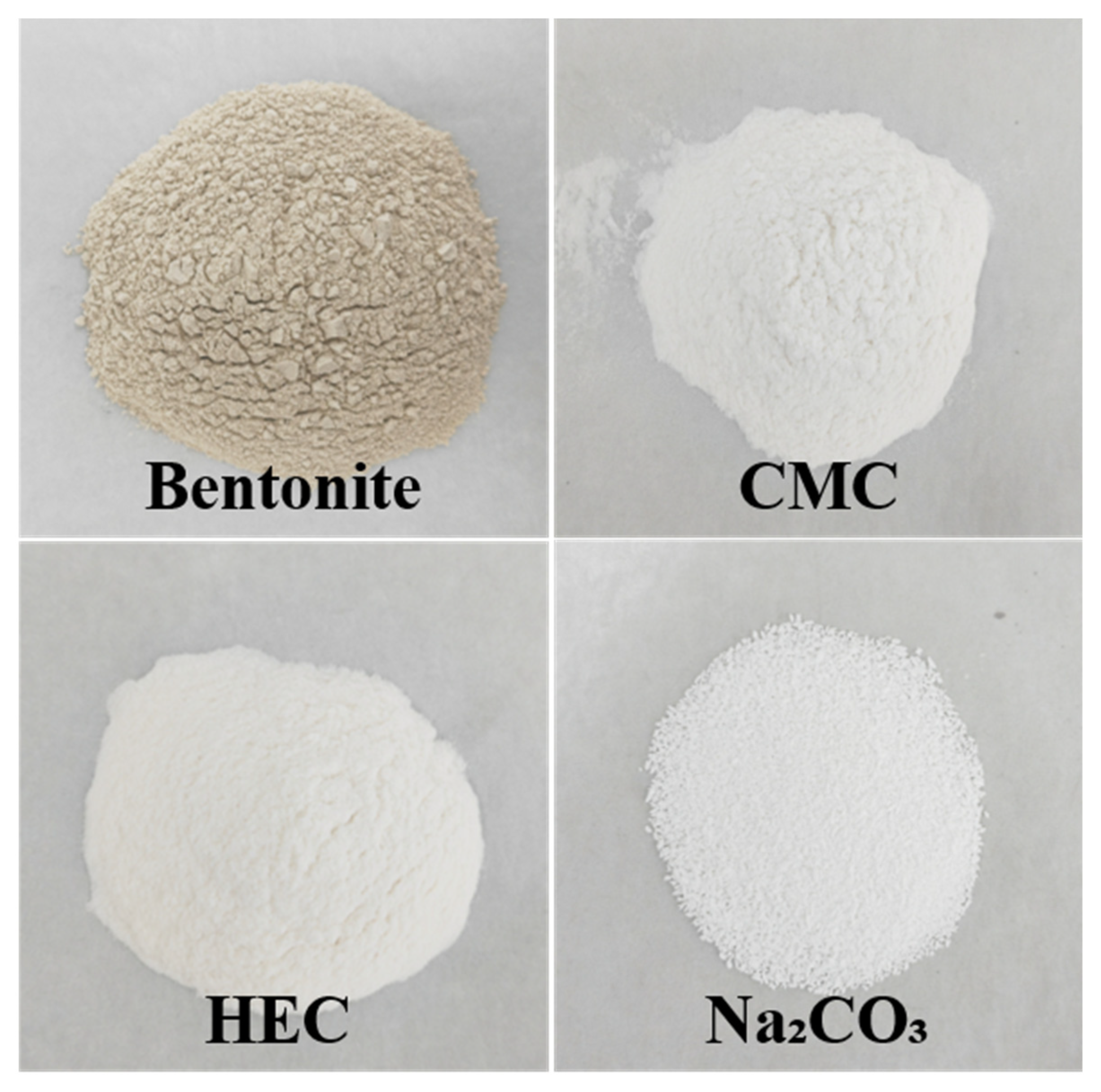
Figure 2.
Experimental instruments.
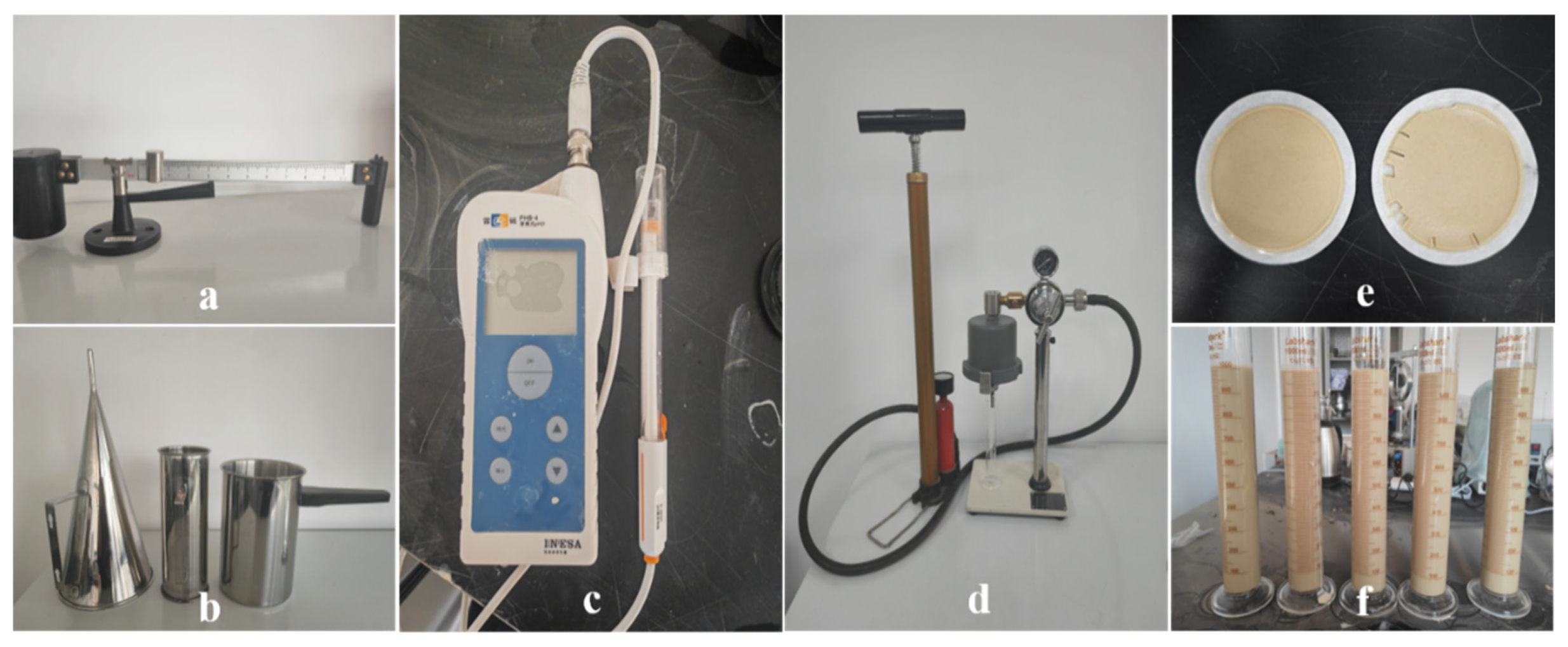
Figure 3.
Schematic of experimental procedure and slurry formulation.
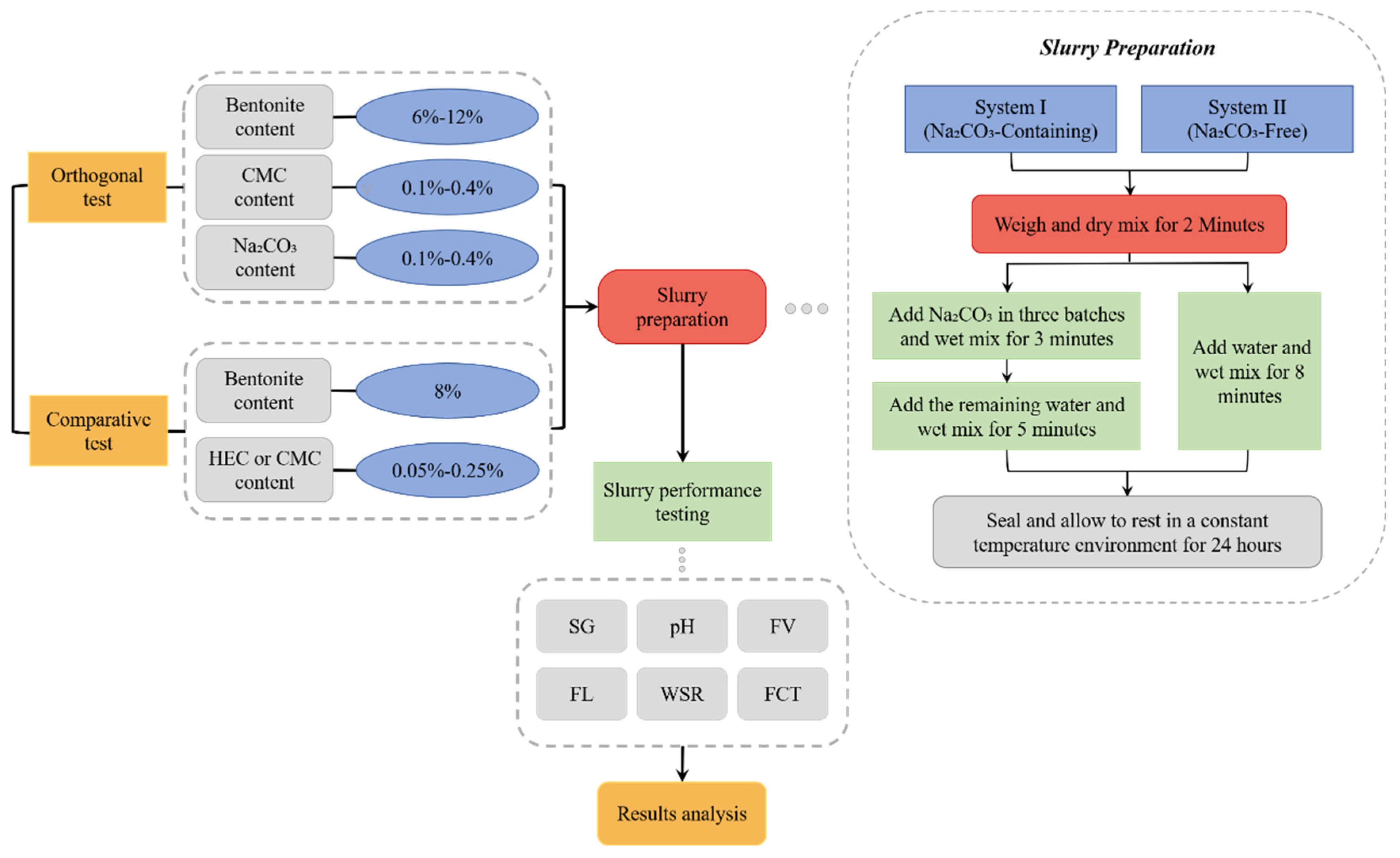
Figure 4.
Hitachi SU3500 field-emission SEM system.
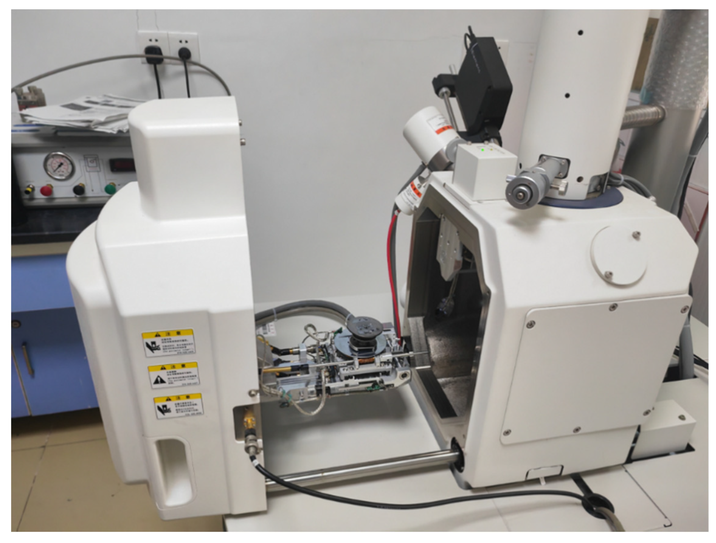
Figure 5.
Effects of three factors on FL.
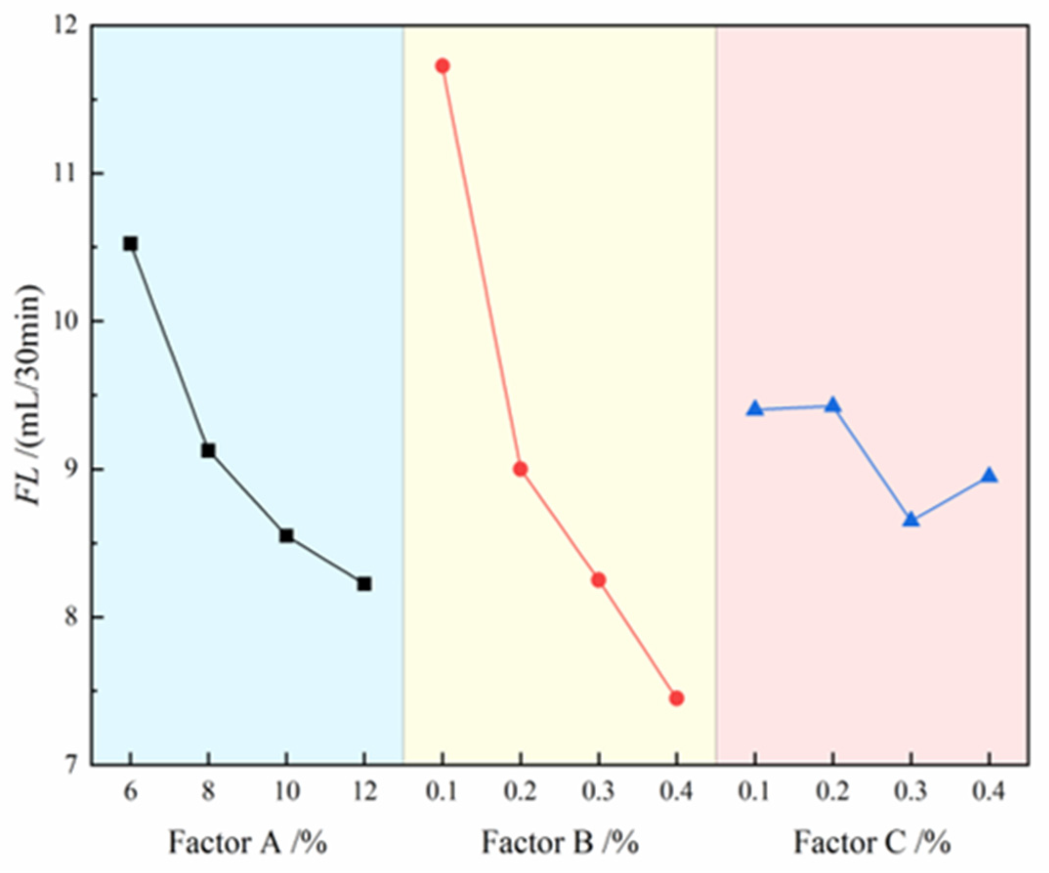
Figure 6.
Effects of three factors on FV.
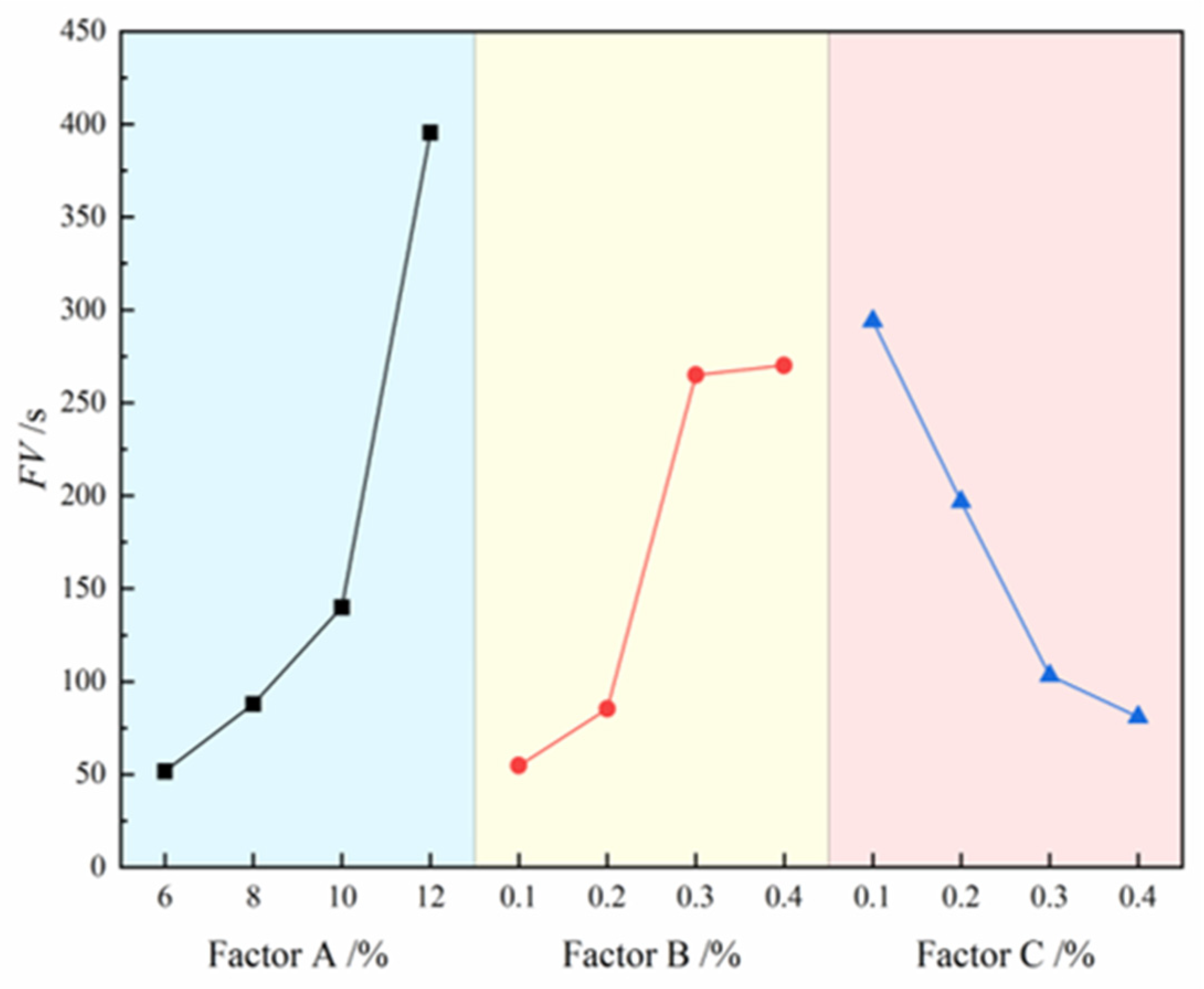
Figure 7.
Effects of three factors on FCT.
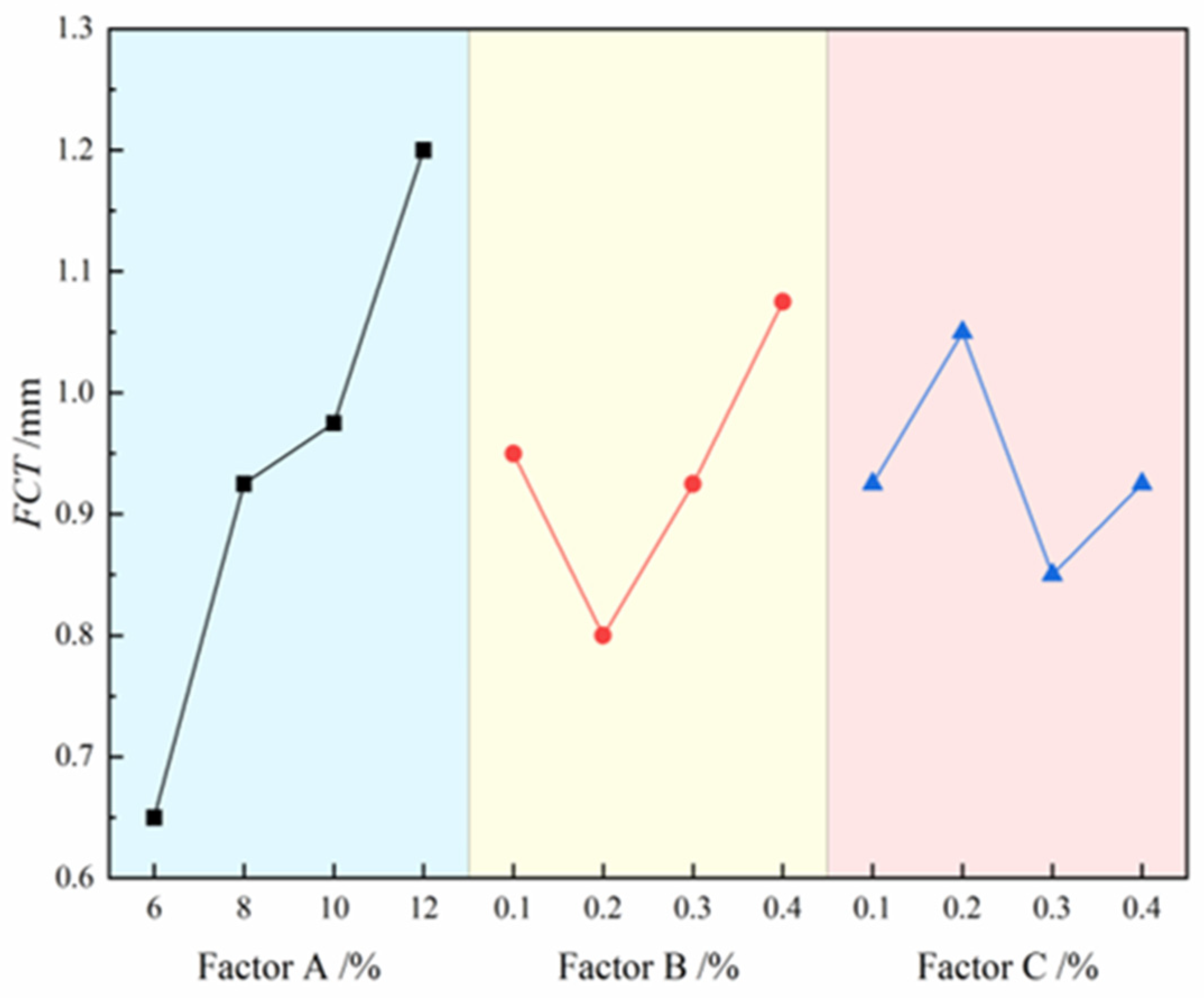
Figure 8.
Photograph of the prepared optimal thixotropic slurry (A₃B₄C₃).
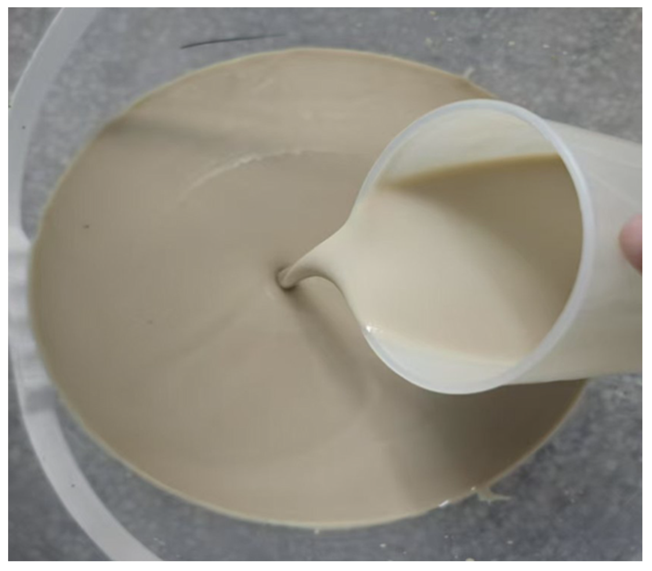
Figure 9.
Effects of HEC/CMC content on FV.
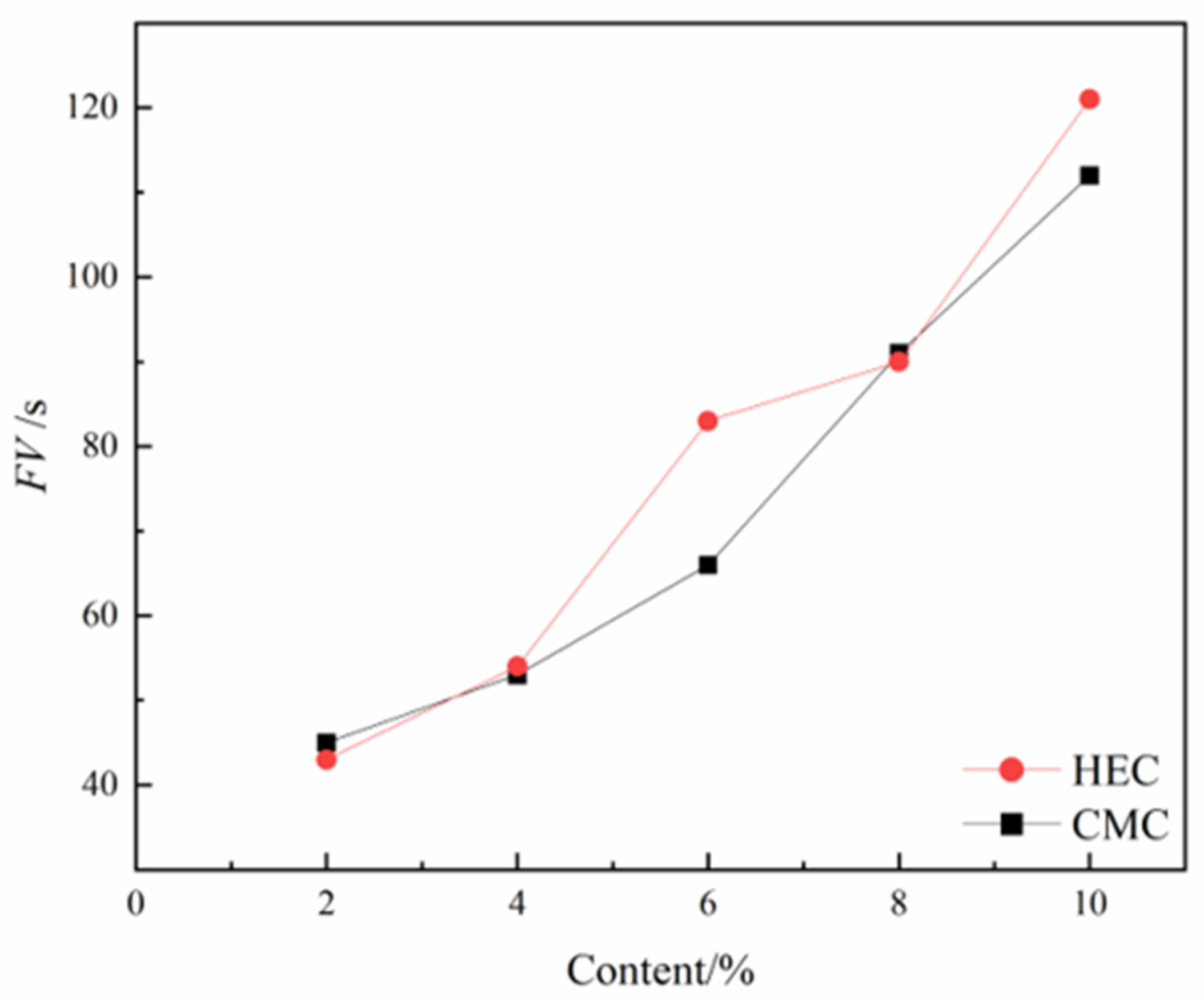
Figure 10.
Effects of HEC/CMC content on FL.
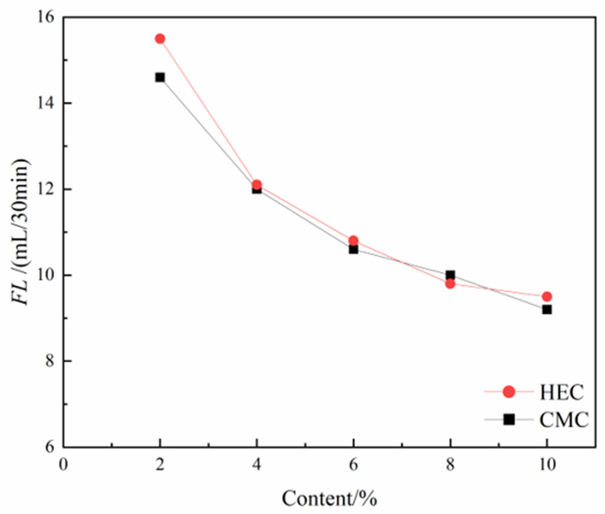
Figure 11.
Effects of HEC/CMC content on pH.
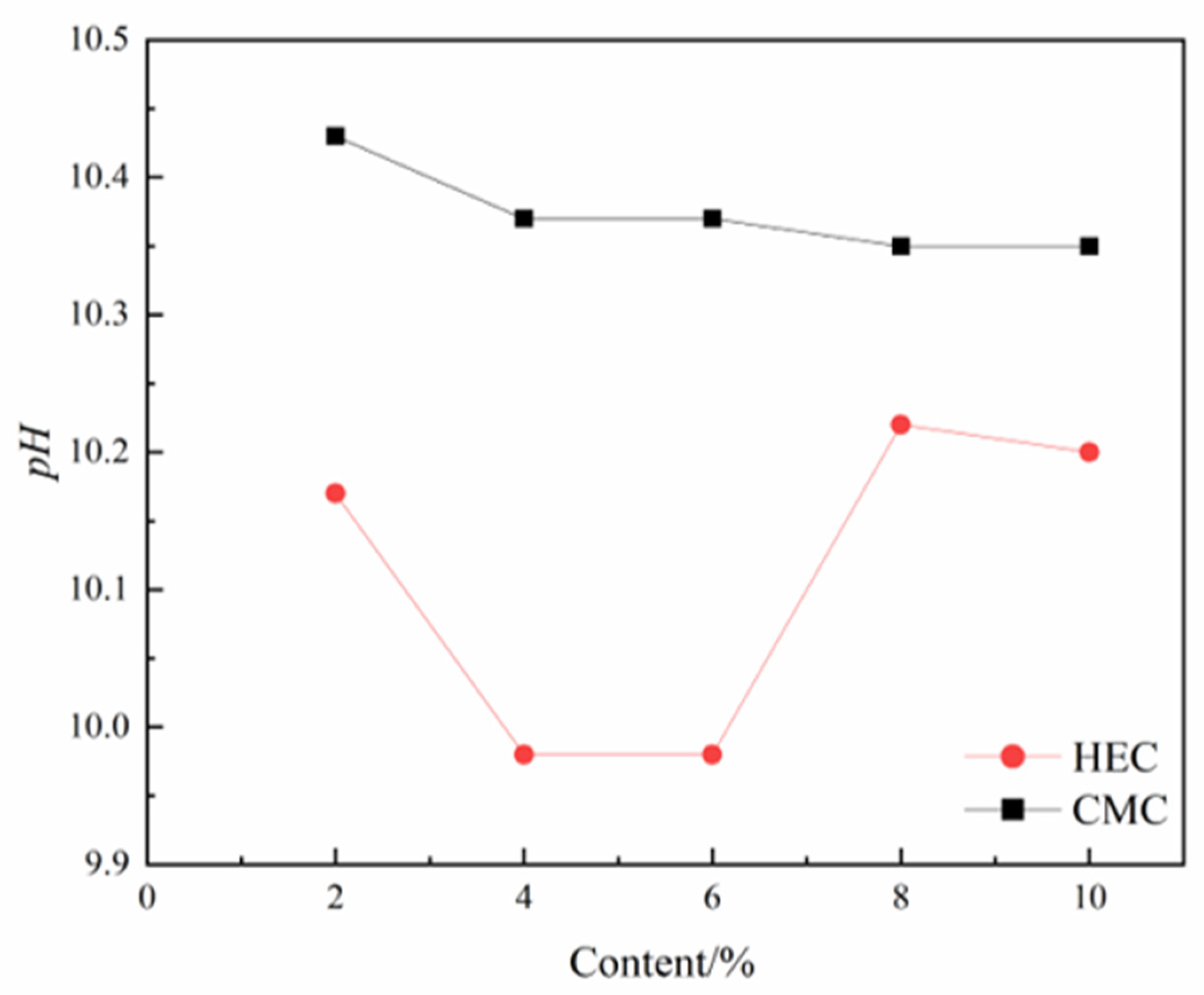
Figure 12.
Effects of HEC/CMC content on SG.
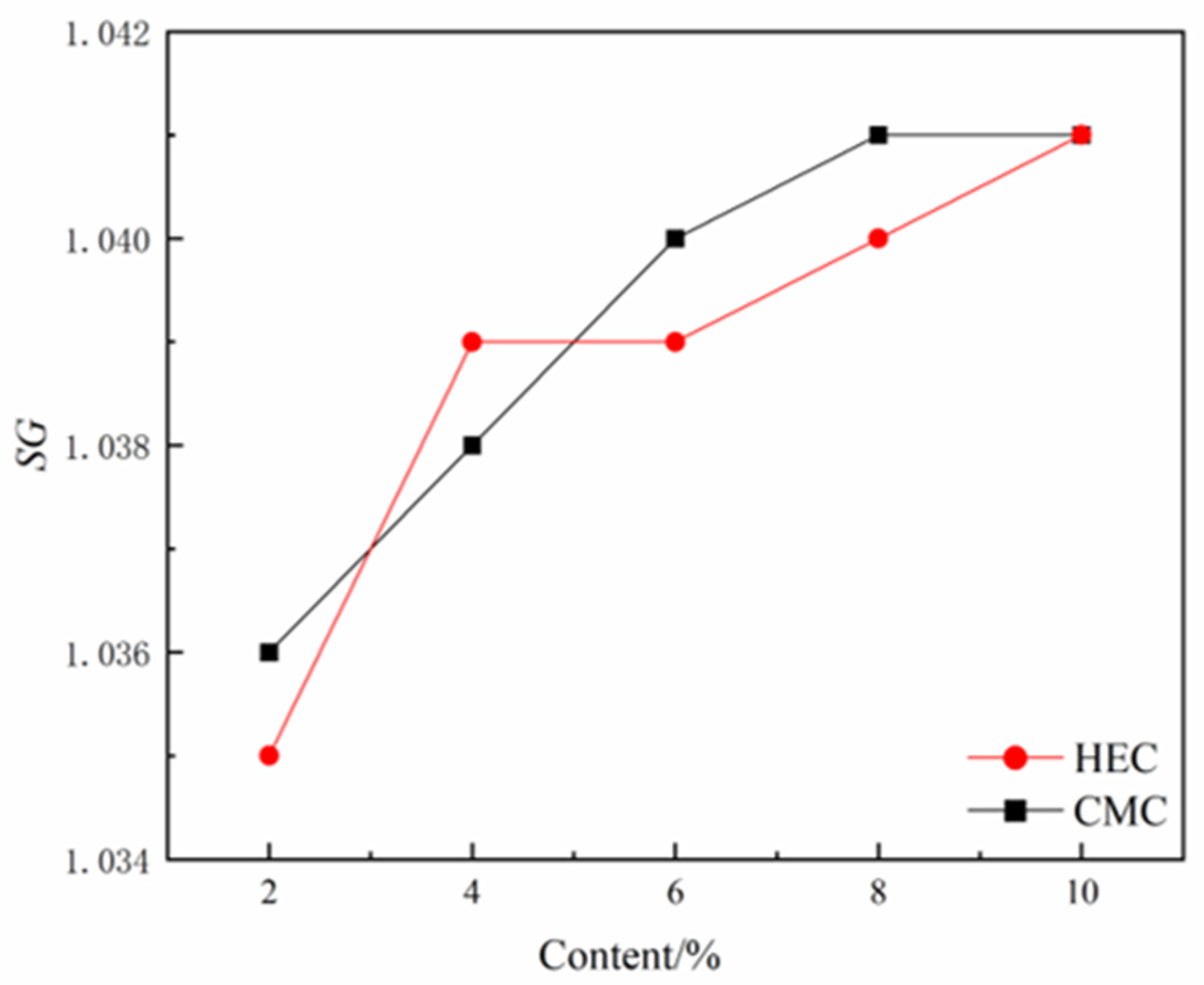
Figure 13.
SEM images of the bentonite-CMC- Na2CO3 ternary system.
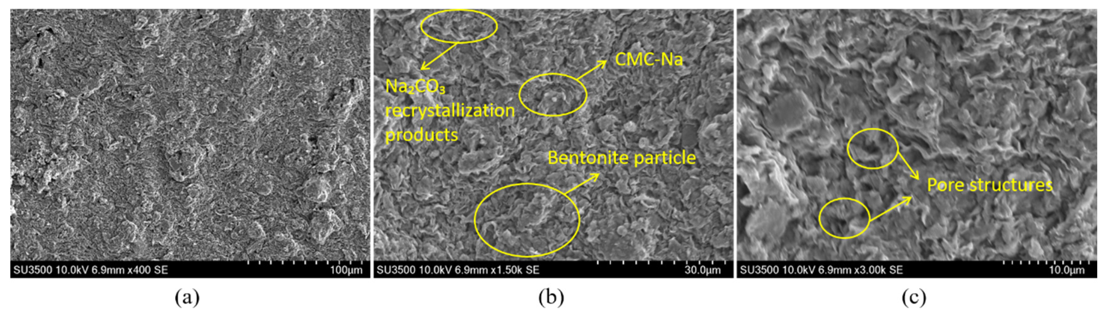
Figure 14.
SEM images of the bentonite-CMC binary system.
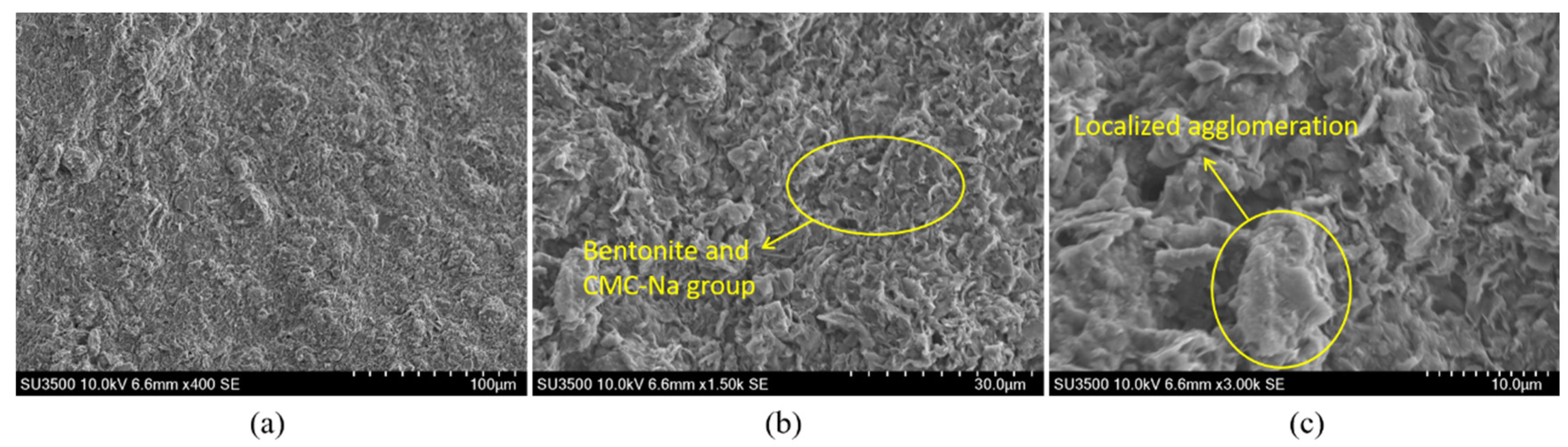
Figure 15.
SEM images of the bentonite-HEC binary system.
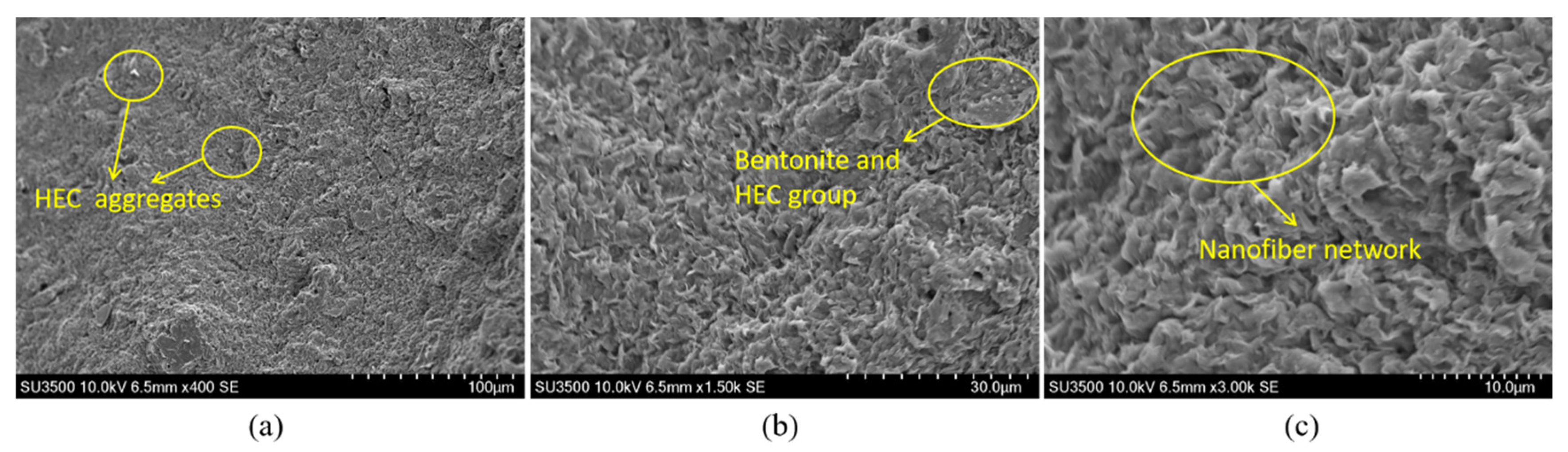

Table 1.
Specifications of raw materials.
| Name | Specification |
| Sodium bentonite | Montmorillonite content ≥75% |
| Gel yield (swelling capacity): 100.2 mL/15g | |
| Na2CO3 | Manufacturer: Shanghai Xilong Scientific Co., Ltd. |
| Purity ≥99.8% (chemically pure grade) | |
| HEC | Viscosity of 2% aqueous solution: 5,000–6,000 mPa·s at 20°C |
| CMC | Viscosity of 20 g/L solution: 800–1,200 mPa·s at 25°C |
| Water | Municipal tap water |
Table 2.
Factors and levels of the orthogonal experiment.
| No. | Factors | Level 1 | Level 2 | Level 3 | Level 4 |
| A | Bentonite content (%) | 6.0 | 8.0 | 10.0 | 12.0 |
| B | CMC content (%) | 0.1 | 0.2 | 0.3 | 0.4 |
| C | Na2CO3 content (%) | 0.1 | 0.2 | 0.3 | 0.4 |
Table 3.
Slurry formulations in the comparative experiment.
| No. | Bentonite content (%) | HEC content (%) | CMC content (%) | Water content (%) |
| HEC-0.05 | 8 | 0.05 | - | 91.95 |
| HEC-0.10 | 8 | 0.10 | - | 91.90 |
| HEC-0.15 | 8 | 0.15 | - | 91.85 |
| HEC-0.20 | 8 | 0.20 | - | 91.80 |
| HEC-0.25 | 8 | 0.25 | - | 91.75 |
| CMC-0.05 | 8 | - | 0.05 | 91.95 |
| CMC-0.10 | 8 | - | 0.10 | 91.90 |
| CMC-0.15 | 8 | - | 0.15 | 91.85 |
| CMC-0.20 | 8 | - | 0.20 | 91.80 |
| CMC-0.25 | 8 | - | 0.25 | 91.75 |
Table 4.
Results of the orthogonal experiment.
| No. | A (%) | B (%) | C (%) | SG | pH | FV (s) | WSR (%) | FL (mL/30min) | FCT (mm) |
| 1 | 6 | 0.1 | 0.1 | 1.020 | 10.68 | 36 | 0 | 13.7 | 0.7 |
| 2 | 6 | 0.2 | 0.2 | 1.023 | 10.80 | 43 | 0 | 11.0 | 0.5 |
| 3 | 6 | 0.3 | 0.3 | 1.030 | 10.98 | 56 | 0 | 9.0 | 0.6 |
| 4 | 6 | 0.4 | 0.4 | 1.031 | 11.11 | 72 | 0 | 8.4 | 0.8 |
| 5 | 8 | 0.1 | 0.4 | 1.038 | 10.70 | 183 | 0 | 8.0 | 1.0 |
| 6 | 8 | 0.2 | 0.3 | 1.040 | 10.89 | 82 | 0 | 8.9 | 1.1 |
| 7 | 8 | 0.3 | 0.2 | 1.038 | 11.02 | 49 | 0 | 8.2 | 0.7 |
| 8 | 8 | 0.4 | 0.1 | 1.037 | 11.11 | 38 | 0 | 11.4 | 0.9 |
| 9 | 10 | 0.1 | 0.2 | 1.053 | 10.57 | 154 | 0 | 8.3 | 0.9 |
| 10 | 10 | 0.2 | 0.1 | 1.050 | 10.77 | 62 | 0 | 11.4 | 1.1 |
| 11 | 10 | 0.3 | 0.4 | 1.051 | 10.93 | 225 | 0 | 7.0 | 1.0 |
| 12 | 10 | 0.4 | 0.3 | 1.058 | 11.09 | 119 | 0 | 7.5 | 0.9 |
| 13 | 12 | 0.1 | 0.3 | 1.068 | 10.68 | 803 | 0 | 7.6 | 1.1 |
| 14 | 12 | 0.2 | 0.4 | 1.070 | 10.80 | 601 | 0 | 6.4 | 1.5 |
| 15 | 12 | 0.3 | 0.1 | 1.069 | 10.96 | 83 | 0 | 10.4 | 1.1 |
| 16 | 12 | 0.4 | 0.2 | 1.068 | 11.11 | 95 | 0 | 8.5 | 1.1 |
Table 5.
Results of range analysis for FL.
| Factors | Mean FL values (K₁) across experimental levels (mL/30 min) | ||||||
| Level 1 | Level 2 | Level 3 | Level 4 | R | Priority order | Optimal combination | |
| A | 10.525 | 9.125 | 8.550 | 8.225 | 2.300 | B-A-C | A₄B₄C₃ |
| B | 11.725 | 9.000 | 8.250 | 7.450 | 4.275 | ||
| C | 9.400 | 9.425 | 8.650 | 8.950 | 0.775 | ||
Table 6.
Results of range analysis for FV.
| Factors | Mean FV values (K2) across experimental levels (s) | ||||||
| Level 1 | Level 2 | Level 3 | Level 4 | R | Priority order | Optimal combination | |
| A | 51.750 | 88.000 | 140.000 | 395.500 | 343.750 | A-B-C | A₃B₂C₃ |
| B | 54.750 | 85.250 | 265.000 | 270.250 | 215.500 | ||
| C | 294.000 | 197.000 | 103.250 | 81.000 | 213.000 | ||
Table 7.
Results of range analysis for FCT.
| Factors | Mean FCT values (K3) across experimental levels (mm) | ||||||
| Level 1 | Level 2 | Level 3 | Level 4 | R | Priority order | Optimal combination | |
| A | 0.650 | 0.925 | 0.975 | 1.200 | 0.550 | A-B-C | A₃B₂C₃ |
| B | 0.950 | 0.800 | 0.925 | 1.075 | 0.275 | ||
| C | 0.925 | 1.050 | 0.850 | 0.925 | 0.200 | ||
Table 8.
Results of the comparative experiment (HEC).
| No. | Key performance indicators of thixotropic slurry | |||||
| SG | FV (s) | WSR (%) | FCT (mm) | FL (mL/30min) | pH | |
| HEC-0.05 | 1.035 | 43 | 0 | 1.0 | 15.5 | 10.17 |
| HEC-0.10 | 1.039 | 54 | 0 | 1.0 | 12.1 | 9.98 |
| HEC-0.15 | 1.039 | 83 | 0 | 1.0 | 10.8 | 9.98 |
| HEC-0.20 | 1.040 | 90 | 0 | 0.8 | 9.8 | 10.22 |
| HEC-0.25 | 1.041 | 121 | 0 | 1.0 | 9.5 | 10.20 |
Table 9.
Results of the comparative experiment (CMC).
| No. | Key performance indicators of thixotropic slurry | |||||
| SG | FV (s) | WSR (%) | FCT (mm) | FL (mL/30min) | pH | |
| CMC-0.05 | 1.036 | 45 | 0 | 1.0 | 14.6 | 10.43 |
| CMC-0.10 | 1.038 | 53 | 0 | 1.0 | 12.0 | 10.37 |
| CMC-0.15 | 1.040 | 66 | 0 | 1.0 | 10.6 | 10.37 |
| CMC-0.20 | 1.041 | 91 | 0 | 1.0 | 10.0 | 10.35 |
| CMC-0.25 | 1.041 | 112 | 0 | 1.0 | 9.2 | 10.35 |
Disclaimer/Publisher’s Note: The statements, opinions and data contained in all publications are solely those of the individual author(s) and contributor(s) and not of MDPI and/or the editor(s). MDPI and/or the editor(s) disclaim responsibility for any injury to people or property resulting from any ideas, methods, instructions or products referred to in the content. |
© 2025 by the authors. Licensee MDPI, Basel, Switzerland. This article is an open access article distributed under the terms and conditions of the Creative Commons Attribution (CC BY) license (http://creativecommons.org/licenses/by/4.0/).
Copyright: This open access article is published under a Creative Commons CC BY 4.0 license, which permit the free download, distribution, and reuse, provided that the author and preprint are cited in any reuse.


