
Submitted:
06 May 2025
Posted:
08 May 2025
You are already at the latest version
Abstract
Antireflection coatings are used in many optical systems for improving their optical performance. Thereby, the target is the suppression of unwanted reflections and/or the increase of the transmittance. In both cases the resulting solutions are identical when no optical losses are relevant. Typically, a proper selection of materials and deposition technique will result in neglectable losses in most applications, and distinguishing between both aims is not necessary. In the case of high energy laser optics, nonlinear optical effects often become relevant and may result in significant changes of the optical performance. In particular, two-photon absorption may provide an additional loss mechanism, which is absent in the linear case. We will present a practical numerical model for calculating transmittance and reflectance of multilayer coatings taking third-order optical nonlinearities into account. Thereby, the impact of different discretization of the complex refractive index profile to the predicted system performance will be investigated. Additionally, aspects for parallelism of the calculations will be discussed. The developed method will be applied for the design of different antireflective coatings matching various types of targets.
Keywords:
antireflection coatings
; nonlinear optic
; two-photon absorption
; third-order optical nonlinearity
; coating design
1. Introduction
Today, optical coatings are applied in practically all branches of optics, with the purpose of modifying optical and non-optical properties of optical surfaces [1]. Antireflection coatings belong to the most frequently produced groups of optical coatings and are indispensable in any transmissive optical system. The design of optical coatings is usually performed in the framework of standard model assumptions [2]. In many antireflection tasks, a broad spectral range and different illumination conditions (angle of incidence, polarization state) must be covered [3,4]. For a wide variety of specifications optimal solutions are well known [5,6,7,8], and the impact of layer number and optical constants to the expected optical performance can be estimated by empirical expressions [9].
In many applications (only performance for s-polarization is specified), in accordance with the maximum principle [10] only two materials with maximum refractive index contrast are required in the coating design. Additionally, further non-optical aspects such as mechanical and environmental stability may have to be considered [11,12].
In particular, the standard model assumes the validity of linear optics, which results in transmittance and reflectance values that do not depend on the light intensity.
However, this result is only true for incident light intensities that are small enough for neglecting any nonlinear optical processes in the coating as well as in the substrate. Nowadays, high-power lasers are widely available and the demand for optical components that work at large laser intensities is increasing accordingly. Often, the most important additional requirement is to achieve the highest possible laser induced damage threshold (LIDT). However, reversible changes in optical performance (for example the reflectance) of a component could be observed in the pre-damage regime and can be explained by the emerging significance of nonlinear effects. In [13] a reversible drop of reflectivity with increasing intensity was observed and could be explained by two-photon absorption in the high refractive index component. Several approaches have been reported for including third-order optical nonlinearities into the calculation of the coating reflectance [14,15,16]. While a calculation of the reflectance might be sufficient for mirrors, this is not valid in the general case. This can be exemplified by an antireflective coating that is to maximize the transmittance in the presence of optical losses.
The motivation of this study is in the formulation of a design recipe for antireflection coatings when third-order nonlinear optical effects cannot be neglected. We will have to formulate certain model assumptions that extend the usual thin film model accordingly.
2. Theory
2.1. Considerations on the Field Strength in an Antireflection Optical Coating in Linear Optics
Let us assume a layered system like shown in Figure 1 a certain number of films (numbered by the index m) is separated from each other by flat infinitesimally thin interfaces (the vertical lines). The light is incident from the right. In Figure 1 the electric fields strength for both travelling directions at the interfaces are visualized. The contribution of the m-th layer can be calculated by the matrix method [17,18,19,20], when the (complex) refractive indices and thickness are given. Here, no damping in the two semi-infinite media substrate and ambient (superstrate) is assumed and therefore the refractive indices and are considered as real numbers.
Transmittance and reflectance are defined as ratios. In the case of normal incidence, we have:
In the case of a perfect antireflective coating, the requirement directly lead to . Additionally, the semi-infinite substrate results in and from the electric field strength in the substrate:
For the antireflective coating we can easily deduct that the electric field strength in the substrate doesn’t depend on the design or optical constants of the selected materials.
In Figure 1, we have restricted our attention to the electric field strength, but of course, the magnetic field of the waves have to be included accordingly. Note that in any stratified system, the spatial dependence of the - and -field must suffice the system of equations [20,21] (here for normal incidence and linear optics only):
with angular frequency , vacuum permeability and vacuum permittivity .
In the case of a single wavelength at a fixed angle of incidence, zero reflectance can be achieved when certain amplitude and phase conditions are fulfilled by the coating. Theoretically this could be achieved by a single layer coating, but the required refractive index of the coating material is not always available in nature.
The two layer antireflecting coating for a single wavelength at normal incidence of light is known as V-coating and has two primitive solutions for the layer thicknesses [22]. In the case of loss-free coatings, an infinite number of additional two-layer solutions can be generated by increasing the optical thicknesses by an arbitrary number of halfwave layers [18]. Thereby, the spatial electric field distributions near both semi-infinite media (regions I and III in Figure 2) are identical for both designs. The electric field strength at the interface between the high and low refractive index material is also identical for both solutions (red, dotted horizontal line) and depends on the refractive indices used. The refractive indices assumed in the present design are summarized in Table 1.
In general, feasible combinations of the refractive indices can be visualized in the Schuster plot (Figure 3) [22]. Commonly, the low refractive index material is located at the interface to the ambient medium (here air) and has a refractive index close to that of the substrate. In Figure 3 this area is highlighted by a green triangle and the position of the assumed refractive indices (Table 1) is marked by a black diamond. As long as the refractive index at the interface to the substrate is larger than the square root of the substrate refractive index, the lower refractive index must be located closest to air (denoted as Sub H L). In the area highlighted in red, this is no more fulfilled (Sub L H) but for typical optical glass substrates this requires optical constants commonly not available from bulk materials. The same applies to the Sub H L region highlighted in yellow.
It is obvious, that for a single wavelength antireflective coating a complete suppression of the reflected light does not require a maximum contrast of the refractive indices.
In Figure 2, the electrical field distribution in section II is symmetric, but is different for both types of the V-Coating. In particular, the observed minimum electrical field strength depends on the refractive index of this section. In general, the refractive index of section II is not limited to the value of the selected high and low refractive index material and can be replaced by a different material. Then, zero reflectance of the coating will persist, when an adapted thickness is used for the layer that replaces the Section II. This finding in combination with Herpin’s concept of equivalent layer for a symmetrical layer sequence [23] has been used to deduct further initial designs with an increased number of layers [24,25,26,27,28].
Figure 4 shows the thus obtained further types of solutions. In (a) the central layer in Section II is the high index material, while in (b) it is the low refractive index material. One layer thickness can be freely selected during the design process. Here, a layer thickness of 20 nm was chosen for the identical two layers of Section II that are adjacent to regions I and III.
Note that the replacement of Section II by a symmetric 3-layer sequence increases the number of layers in the coating only by 2. In other words, instead of a two-layer coating, we now obtain a four-layer coating. The replacement procedure may thus be understood as the addition of a pair of layers and subsequent adoption of the thicknesses. We will make use of this approach later in Sects. 3.4 and 3.5.
So far our discussion was restricted to linear optics. In applications with high power lasers, several specific aspects are relevant:
- high intensity of the laser can cause damage of the coating (quantified by laser induced damage threshold LIDT)
- even in the pre-damage regime nonlinear behavior of the materials can decrease the optical performance
- commonly only a single wavelength or a very limited wavelength range must be considered
- substrate is not only the sheet “holding” the coating, but it may also be curved (lens) or provide the main functionality when nonlinear effects are used to generate light of a different wavelength (four-wave mixing: harmonic generation, sum- and difference-frequency generation, spontaneous parametric down-conversion, …). Often, the corresponding materials are optically anisotropic crystals.
Our further focus will be on the second and third points.
2.2. Basic Assumptions to Consider Nonlinear Effects
In conventional thin film optics, the electric dipole approximation and optically isotropic materials (without magnetic response) are assumed. Thereby, the time-dependent electric field induces a macroscopic polarization in the medium [29]:
Thereby, is the real response function of the medium, the time and the integration variable stands for the time delay.
In the case of nonlinear optics, the macroscopic polarization can be generalized to [29]:
In the more common frequency domain, the corresponding formulation of the macroscopic polarization is
with (linear) susceptibility , quadratic susceptibility and so on. In the case of third-order nonlinearity addressed in this article, the contributions to the macroscopic polarization are limited to and .
The spectral dependence from the angular frequency of the linear susceptibility can be expressed by the complex dielectric function , the complex refractive index or the (ordinary) refractive index and the extinction coefficient using the following equations:
In the case of a monochromatic input, the cubic susceptibility is related to the nonlinear refractive index and two-photon absorption coefficient by the following set of equations:
Thereby, is the velocity of light in vacuum.
For simplification, in the further equations the absence of linear absorption ( will be assumed. In a stratified medium the Maxwell equations can be reduced to a boundary value problem of two differential equations. In the case of normal incidence, and neglecting all other possible nonlinear optical effects except nonlinear absorption and refraction phenomena, the following wave equations can be obtained as a generalization of Equation (3):
The system of equations (9) is an expression of specific model assumptions, namely the significance of linear optical processes combined with nonlinear refraction and absorption, while neglecting all other nonlinear interactions. In contrast to the linear case, in this model, each material is characterized by a set of four optical constants, namely , , and (see Table 1).
2.2. Iterative Approach for Calculation of the Spectral Response
2.2.1. Runge-Kutta Calculation
In the case of a semi-infinite substrate no back travelling wave will occur and the boundary conditions at the interface coating / substrate (i.e., at in Figure 1) can easily be formulated. Then, the Maxwell equations can be numerically solved by Runge-Kutta [16]. The resulting spatial distribution of the electric and magnetic field can be used for calculation of transmittance and reflectance according to the corresponding definition as intensity ratios.
This approach works very efficient when the intensity dependence of transmittance and reflectance is to be calculated. Calculation of the response to a given intensity of the incident light is more challenging, because this requires defining a boundary condition at the interface coating / ambient, i.e., at . In this case, the following iterative approach can be used [16]:
- calculate transmittance of the coating for the linear case
- estimate the expected electric field strength at according to the definition of the transmittance
- calculate spatial distribution of the electric and magnetic field for the given electric field strength at
- adapt electric field strength at according to the remaining discrepancy in the electric field at
- repeat with step 3 until the discrepancy is below a certain threshold
2.2.2. Iterative Matrix Method
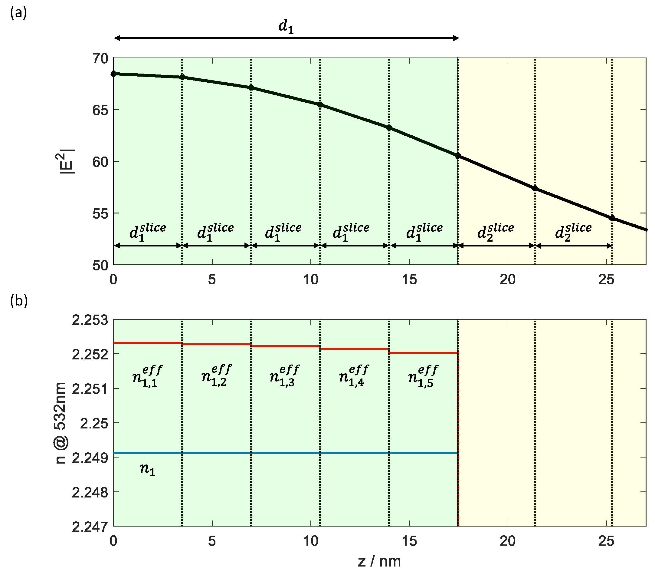
This is a rather tedious procedure, and therefore, an alternative approach seems prospective and has been already successfully applied for high reflective coatings [15]. Basically, all layers are sliced in sufficiently thin homogeneous layers and the linear optical constants are replaced by “effective” optical constants calculated based on individual average electrical field strength (compare Equations (10), (11)). Here, “sufficiently thin” means, that the slice thickness must not exceed a certain threshold value , obtained as a compromise between calculation time and accuracy. Considerations on the choice of form the content of the later Section 3.1.
The electric field strength at the boundaries of the slices can be calculated directly as outlined in [30,31,32].
In the initial stage, the resulting “effective” optical constants are:
In subsequent iterations, the corresponding spatial distribution of the electric field strength is used to update the “effective” optical constants:
Figure 5.
(a): Polyline representation of the spatial distribution of the electric field in the linear case; (b): linear (blue) and effective refractive index (red) for 109 W/cm2 of the sliced layers 1 (green background) and 2 (yellow background) of the conventional V-coating. Boundaries of the slices are marked by dotted lines.
2.3. Design Process
There are currently no established design approaches that consider the nonlinear behavior of the materials. For better differentiation, the terms “conventional” and “nonlinear” are used below to distinguish whether nonlinear effects are also considered or not.
The partial discrepancy function use a weighted difference between modelled value and target value and is commonly [19] defined as
Thereby, is the number of target values, are the corresponding tolerances and is the power (often 2).
In the following, it will be useful to introduce various target functions , , and , which will be minimized by different designs. They are introduced in Equations (13a) - (13c). For and (, the common target value for an antireflection coating is zero and the modeled values for both quantities are always non-negative. For this reason, a power of 1 is a naturally choice for the discrepancy function and represents the weighted average value. For the design calculations performed here, the quantities were weighted equally and therefore .
It is obvious that the number of required parameters must be increased to consider the nonlinear effects. Besides the layer thicknesses, in conventional designs, the refractive index and the extinction coefficient are commonly used. In the nonlinear case, knowledge on the real and imaginary parts of the cubic susceptibility (we neglect the tensor character of for simplicity here) are required as well.
The simplest way to generate a nonlinear design is to refine a conventional design [33].
While in most cases we will use targets and , for a special specification, turned out to deliver the best results.
As long as the number of parameters is small, a “brute force” approach could be used to find the global minimum of the function. Thereby, the value of the discrepancy function is calculated at each point of a sufficient fine multidimensional grid. In conventional designs for a single wavelength, halfwave layers will have no effect and can be eliminated from the design. In the nonlinear case, an additional halfwave layer will mainly increase the absorption. For this reason, commonly the optical thickness of individual layers should not exceed the halfwave optical thickness.
In Figure 6 and Figure 7 a logarithmic plot of the discrepancy function is shown for different light intensities. Thereby, different kind of targets and have been used. On the left, target is used, while on the right, target is relevant. In the case of an intensity of 109 W/cm2 both representations are very similar and show a nearly periodic dependence when the thickness is increased by integer multiples of the halfwave optical thickness [34]. The zoomed view (Figure 6c,d) of a local minimum shows, that the corresponding layer thicknesses at the minimum are nearly identical for both discrepancy functions.
In the case of an intensity of 1011 W/cm2 the quasi-periodicity persists only when target is used. The layer thickness of the high refractive index material decreases and is different for both discrepancy functions. Additionally, the area of discrepancy function below 10-8 (estimated numerical precision of floating-point calculations) is shrunk for reflectance and completely disappeared for transmittance.
In the conventional design process, various methods summarized as gradual evaluation are a well-established approach [35]. Thereby, either a new layer is added, or the layer thickness of an already existing layer is increased until a different local minimum of the discrepancy function is reached. In this case, the layer number is kept constant or increased by one. If the new layer is added on an arbitrary position, the layer number is increased by two. In the case of very thin layers, this is known as the needle algorithm [36].
In the case that only a single intensity is specified, the concept of effective optical constants enables a straightforward implementation of established design approaches to the nonlinear case. In the case of a limited number of required intensities, an extension of the multi-environment concept implemented in OptiLayer [37] and OTF Studio [38] seem to be prospective.
In the case of a specification that only contains a single wavelength, the concept of Herpin [24] is a well-suited approach to increase the layer number [24,25,26,27,35,39,40]. At a single wavelength, a symmetrical three-layer sequence with and performs identical to a single layer with equivalent thickness and refractive index. Adding such a layer sequence at the interface to air, the linear optical response of the coating kept constant when the equivalent refractive index is identical to the refractive index of the ambient media. For the assumed optical constants of the high and low refractive index materials, this can be achieved for various thickness combinations (Figure 8).
3. Results
3.1. Impact of the Maximum Slice Thickness
For each individual layer with thickness the number of slices is calculated according to the maximum thickness of slices and used to generate slices with equal thickness (see Figure 5)
In the case of the V-coating specified for a wavelength in the visible spectral range (VIS) a maximum thickness of slices nm was sufficient (Figure 9). The situation is similar to the design of rugate filters, when inhomogeneous layers are replaced by homogeneous slices during the design process [41]. In the VIS this is consistent with the condition .
For larger values of ceiling in Equation (14) has only a small impact to the number of slices of the thin high refractive index layer and the calculated reflectance values of the coating remain nearly constant (Figure 9) until the resulting number of slices is further decreased. Even with a maximum slice thickness of 10 nm the relative deviation for the reflectance is only ~1.5% for both intensities.
3.2. Convergence
When implementing the iterative matrix method, the required number of iterations until convergence of the result is important. In the case of the investigated antireflective coatings, for intensities corresponding to small deviations between linear and effective optical constants only ~3 iterations are required (Figure 10a). In the case of very high intensities the basic assumptions are no longer valid. For an intensity of 1012 W/cm2, the method still converges and reaches its final value after approx. 50 iterations (Figure 10b). Nevertheless, the correctness of the result is questionary.
Similar results are obtained when investigating the convergence of the calculated transmittance.
3.3. Normal Incidence, Single Wavelenth AR-Coatings Optimized for a Single Intensity
As already explained, the additional specification of the intensity is required to take nonlinear effects in the coating design into account. Wavelengths, angles of incidence, polarizations and light intensities must therefore be specified for an antireflection coating. In the following, we will first consider the simplest case: The antireflection coating should only be applied for a single wavelength, normal incidence of light and a specified light intensity. The discrepancy function with target values according to Equations (13a) and (13b) are practically the same for this problem, because the target light intensity 1011 W/cm2 only acts as a scaling factor. Due to the losses caused by the two-photon absorption, the discrepancy function with target values according to Equations (13a) and (13c) are different and lead to different solutions accordingly. The conventional V-coating is also sufficient for laser applications [42] and was used as the starting design for the refinement in both cases. The intensity-dependent performance for both target values and conventional V-coating has recently been published in [2] and is shown in Figure 11. Layer thicknesses for the three different designs are summarized in Table 2.
While the conventional V-coating shows a monotonic increase in both target values with the light intensity, the optimized designs show a clearly pronounced minimum in reflectivity. For the -optimized design, this minimum is naturally observed at the specified light intensity and achieves values in the range of the numerical accuracy. The design for maximum transmittance, on the other hand, only reaches its minimum reflectance at a slightly higher light intensity and, although it has a low reflectance, is significantly larger than for the design optimized for minimum reflectance. Both optimized designs have an almost constant transmission and reflectivity at low light intensities, but this is significantly worse than with the conventional V-coating.
Figure 12 shows the spatial distribution of the electric field strength ((a) and (b)), the effective refractive index ((c) and (d)) and the effective extinction coefficient ((e) and (f)) for the conventional V-coating and the design with minimum reflection for the specified light intensity of 1011 W/cm2 and for an increased light intensity of 1012 W/cm2.
For the intensity of 1011 W/cm2(blue curves in Figure 12) the curves deviate only slightly from those calculated in the linear optics range as shown in Figure 2a,c. For the conventional V-coating, for example, the electric field strength at the interface to air is slightly higher than in the linear case, which corresponds to 100%. For the optimized design for minimum reflection at this intensity (right column), the spatial field strength distributions look similar to the conventional case. Additionally, the effective optical constants remain close to their linear counterparts. For the intensity of 1012 W/cm2 (red curves in Figure 12) on the other hand, the deviations to Figure 2 are already significant. This is consistent with the estimated upper limit for the light intensity due to the poor convergence in the previous section.
3.4. Normal Incidence, Single Wavelenth AR-Coating Optimized for Two Intensities
The AR coating from the previous chapter demonstrated that almost complete anti-reflection can be achieved for a single light intensity with a two-layer system. However, even small deviations from the specified intensity led to a significant increase in reflectivity, so that in practice somewhat more complex and therefore less sensitive design solutions appear desirable.
For antireflective coating at high intensities, the possibility of using an additional pair of layers to achieve almost complete anti-reflective coating for a further light intensity was investigated. Now, minimum reflectance for intensities 109 W/cm2 and 1011 W/cm2 for a wavelength of 532 nm and normal incidence of light are required. The dependence of the reflectance from light intensity for the deducted design (Table 3) is shown in Figure 13. Now, a sharp drop of the reflectance for both specified intensities can be observed. Again, the reflectance level at lower intensities nearly remains constant, but is significantly lower in comparison to the optimized two-layer coating from the previous section.
3.5. Normal Incidence, Single Wavelenth AR-Coatings Optimized for an Intensity Range
This section presents different design solutions for the intensity range 109 W/cm2 to 1011 W/cm2. The 201 discrete intensities used for this form a geometric series and are therefore equally distributed in the logarithmic representation. Although the high number of support points for the light intensity is associated with a significantly increased computational effort, it improves convergence, as almost complete antireflection coating only appears possible for a few discrete intensities due to the limited number of layers. Additionally, the reflected intensity (Equation (13b)) instead of the reflectance (Equation (13a)) was used to reduce problems with numerical stability when a sum of very small value is calculated.
Again, initial design solutions for up to 8 layers have been deducted this way.. Layer thicknesses for the generated designs are outlined in Table 4.
For the design with 10 layers a different approach has been applied. In this case, a 100-layer coating with identical layer thickness for all layer has been used as starting design for the refinement. In the intermediate results, the layers with a thickness of almost zero were removed from the design. Finally, a 10-layer design was found. It is obvious, that the thickness of the first layer is too small for a practical realization of the design, so that this layer should be removed. Then, the small contrast between the new initial layer and the substrate can be used to eliminate the former 10th layer as well without a serious impact to the discrepancy function. The resulting design contains 8 layers and is close to the already deducted solution for an 8-layer coating. After a further refinement, the designs become identical.
In Figure 15, the dependence of the reflectance from light intensity and the spatial electric field distribution for the limiting value of the light intensities are shown for all designs from Table 4. Within the specified range of the light intensities, only up to three reflectance minima are observed. This could be an indication, that the number of minima could not further increased by adding a pair of layers.
Nevertheless, an increased number of layers results in a significant drop of the discrepancy function (Figure 16).
3.6. Parallelism of the Calculations
The hardware in modern computers supports the parallel processing of calculations. Commercially available processors contain several processor cores that enable different parts of a task to be processed simultaneously. Hyperthreading further increases the number of tasks that can be performed simultaneously. Many modern graphics cards contain a large number of graphics processors that can also be used for calculations. This means that a significant acceleration can be achieved by dividing the calculations appropriately. The additional effort involved in organizing and coordinating the tasks can negate the performance advantage of parallelization if the division is too small.
For this reason, the iterative calculation of the characteristic matrix of the film stack [17] at a given intensity was not parallelized. In contrast, local optimization offers a significantly higher potential for parallelization, as the calculation of the discrepancy function and its partial derivatives requires only a small exchange of data. With an Intel i9-13900 processor, an acceleration of the calculations by a factor of 2-3 could be achieved.
Methods adapted to multilayers for global optimization [43,44] that use different starting points are also suitable and have led to almost complete processor utilization.
Parallelization can be achieved particularly easily for the anti-reflection coating for an intensity range, as the calculations of the discrepancy function for the 201 specified interpolation points can be carried out independently and in any order. Almost complete processor utilization was also achieved here. During a calculation lasting several hours the processor temperature rising to 94°C despite water cooling, thus remaining only just below the maximum permitted processor temperature. The measured clock frequency was stable at 5500 MHz and thus at the maximum turbo boost frequency. With this approach, the parallel implementation was accelerated by a factor of ~9 compared to the sequential algorithm.
4. Discussion
Let us emphasize at this point, that we have presented model calculations in order to investigate challenges and chances of antireflection designs specially suited for light intensities where nonlinear optical effects become significant. Our model basically considers the effect of nonlinear absorption, while other possible nonlinear optical interactions have not been taken into account. At the moment we cannot present experimental data for confirmation or falsification of the thus obtained simulation results.
Let us further emphasize that our approach is designed for the consideration of weak nonlinearities. This has been emphasized when discussing convergence topics, and it is consistent with the chosen structure of Equations (5) and (7).
In agreement with the restriction to weak nonlinearities, the natural choice was to start design development from well-established AR design solutions in linear optics. We therefore started from traditional V-coatings, restricting our attention to almost homogeneous and absorption-free traditional optical coating materials [45]. We mention in this context, that AR solutions basing on heterogeneous coating materials (porous coatings, motheye-structures – compare [46,47]) have been developed in the past, thus extending the range of accessible refractive index combinations in Figure 3. Suchlike heterogeneous materials have not been addressed in our study, particularly because we have no reliable information about their nonlinear optical properties.
This brings us to the basic critical point in our study, namely the acquisition of optical constants. While in linear design, the knowledge of two optical constants n and K might provide a complete description of the material response, in our model, already 4 optical constants need to be known. Nonlinear optical material characteristics may be measured, but this requires complicated and cost-efficient equipment [48,49]. Fortunately, manageable theoretical models for the frequency dependence of these quantities exist, and we would like to refer in this connection to the model of Sheik-Bahae [50]. With a few reliable experimental points available for calibration, such models may be used for predicting the non-linear optical constants at any wavelength of interest.
Two-photon absorption represents the basic specific loss-mechanism in our approach. Therefore, in order to maximize the performance of the coatings, the efficiency of two-photon absorptions should be minimized. When remembering Equation (5), we have:
From here we see two basic research directions in this connection:
Material design: reduction of the imaginary part of : As two-photon absorption occurs when the incident light photon energy exceeds half the optical gap of the corresponding material [50], optical materials with a tailored value of their optical gap seem promising. Recently, several studies explored the potential of optical nanolaminates for optical band gap engineering by explicit use of confinement effects [51,52]. We see such nanolaminates as potential materials for constructing superior antireflection coatings for use at large light intensities [53].
Coating design optimization: Reduction of : The effect of absorbing fractions in a design may also be minimized by a suitable choice of the individual layer thicknesses [Spiller, Larruquert]: For that, the absorbing fractions must be minimized in thickness, and electric field strength maxima should be spatially removed from the absorbing fractions. This is essentially the way we have gone in our study. Note that the incident light intensity now appears as an additional design parameter: The obtained design is best suited for the assumed light intensity but may be unsuitable for use at other light intensities. This offers space for the definition of unconventional reflection (or transmission) targets: one might try to design coatings optimized for a certain set of light intensities, or even a certain intensity range. So far these are conclusions from the presented numerical study only, but they offer perspectives for designing antireflection coatings specially suited for applications when large light intensities are employed.
5. Conclusions
In this paper, we have discussed various aspects for the modelling, simulation and design of antireflective coatings where third-order nonlinearities must be considered. This is particularly important for laser applications. In this case, only a single wavelength needs to be taken into account. In the theoretical section, a brief description of the underlying theoretical model was given. Additionally, two different approaches for the implementation where outlined. The presented iterative matrix method has proven to be advantageous, as it can be realized as an add-on to the usual software packages in the field of linear optics. Not only transmittance and reflectance can be calculated, but also all other quantities supported by the underlying software, such as phase, group delay and group delay dispersion. In addition, build-in design approaches can provide some support in accounting for third order nonlinearities when using the concept of effective optical constants.
The developed method has been applied to generate different design solutions for antireflective coatings at high light intensities. The conventional V-coating can be adapted to a single light intensity through refinement, but reacts sensitively to intensity fluctuation. The sensitivity can be reduced if a larger number of layers (~6-8) are used. The concept of Herpin’s equivalent layer can be applied for this purpose. A larger number of layers also leads to a significant reduction in the average reflected light intensity.
Additionally, it turned out that a slice thickness of ~1 nm is sufficient for accurate calculations in the visual spectral range and that only a few iterations are required for the assumed optical constants and a light intensity up to 1011 W/cm2. With the developed parallel implementation of the discrepancy function the calculation was accelerated by a factor of ~9 compared to the sequential algorithm. A further acceleration seems to be achievable, when a graphics processing unit (GPU) is used for parallelism in the implementation of the matrix algorithm.
Author Contributions
Conceptualization, S.W. and O.S.; methodology S.W. and O.S.; software S.W.; writing—original draft preparation, S.W.; writing—review and editing, O.S.; All authors have read and agreed to the published version of the manuscript.
Funding
This research was funded by Fraunhofer Society, grant number 510076 and by Federal Ministry of Education and Research (BMBF), grant number 13F1007G.
Institutional Review Board Statement
Not applicable.
Informed Consent Statement
Not applicable.
Data Availability Statement
No data available.
Conflicts of Interest
The authors declare no conflicts of interest.
References
- Dobrowolski, J. A. Antireflection coatings: key optical components. In: SPIE 2005, 596303.
- Stenzel, O.; Wilbrandt, S. Theoretical Aspects of Thin Film Optical Spectra: Underlying Models, Model Restrictions and Inadequacies, Algorithms, and Challenges. Appl. Sci. 2025, 15, 2187. [Google Scholar] [CrossRef]
- Janicki, V.; Wilbrandt, S.; Stenzel, O.; Gäbler, D.; Kaiser, N.; Tikhonravov, A.; Trubetskov, M.; Amotchkina, T. Hybrid optical coating design for omnidirectional antireflection purposes. Journal of Optics A: Pure and Applied Optics 2005, 7, L9–L12. [Google Scholar] [CrossRef]
- Liou, Y.-Y. Design of Wide-Angular-Incidence Antireflection Coating over Visible Spectral Region. Japanese Journal of Applied Physics 2006, 45, 4051. [Google Scholar] [CrossRef]
- Tikhonravov, A. V.; Dobrowolski, J. A. Quasi-optimal synthesis for antireflection coatings: a new method. Applied Optics 1993, 32, 4265. [Google Scholar] [CrossRef]
- Dobrowolski, J. A.; Tikhonravov, A. V.; Trubetskov, M. K.; Sullivan, B. T.; Verly, P. G. Optimal single-band normal-incidence antireflection coatings. Applied Optics 1996, 35, 644. [Google Scholar] [CrossRef]
- Schallenberg, U. Design principles for broadband AR coatings. In: SPIE 2008, 710103.
- Jin, J.; Jin, C.; Li, C.; Deng, W.; Chang, Y. Optimal design and fabrication method for antireflection coatings for P-polarized 193 nm laser beam at large angles of incidence (68°–74°). Journal of the Optical Society of America A 2013, 30, 1768–1771. [Google Scholar] [CrossRef]
- Amotchkina, T. V. Empirical expression for the minimum residual reflectance of normal- and oblique-incidence antireflection coatings. Applied Optics 2008, 47, 3109. [Google Scholar] [CrossRef]
- Tikhonravov, A. V. Some theoretical aspects of thin-film optics and their applications. Applied Optics 1993, 32, 5417–5426. [Google Scholar] [CrossRef]
- Schulz, U.; Kaiser, N.; Schallenberg, U. B. AR-hard broadband antireflective coatings generated by a controlled needle-optimization technique. In Proceedings of the Optical Interference Coatings, Tucson, AZ, USA, 27 June–4 July 2004; OSA Technical Digest Series. Optica Publishing Group: Washington, DC, USA, 2004. paper TuB2. [Google Scholar]
- Schallenberg, U. B. Nanostructures versus thin films in the design of antireflection coatings. In: SPIE 2011, 81681N.
- Razskazovskaya, O.; Luu, T. T.; Trubetskov, M. K.; Goulielmakis, E.; Pervak, V. Nonlinear behavior and damage of dispersive multilayer optical coatings induced by two-photon absorption. In: SPIE International Society for Optics and Photonics, 2014, 92370L.
- Amotchkina, T.; Trubetskov, M. K.; Fedulova, E.; Fritsch, K.; Pronin, O.; Krausz, F.; Pervak, V. Characterization of Nonlinear Effects in Edge Filters. In: OSA 2016, ThD.3.
- Stenzel, O.; Wilbrandt, S. Theoretical study of multilayer coating reflection taking into account third-order optical nonlinearities. Applied Optics 2018, 57, 8640–8647. [Google Scholar] [CrossRef]
- He, J.Y. Numerical Study of Nonlinear Response in Dielectric Multilayer Mirrors; Research lab Report, Abbe School of Photonics; Friedrich-Schiller-Universität Jena: Jena, Germany, 2021. [Google Scholar]
- Thelen, A. Design of Optical Interference Coatings; McGraw-Hill Book Company: New York, NY, USA, 1989. [Google Scholar]
- Macleod, H.A. Thin-Film Optical Filters; Adam Hilger Ltd.: Bristol, UK, 1986. [Google Scholar]
- Furman, S.A.; Tikhonravov, A.V. Basics of Optics of Multilayer Systems; Edition Frontieres: Gif-sur-Yvette, France, 1992. [Google Scholar]
- Stenzel, O. The Physics of Thin Film Optical Spectra: An Introduction, 3rd ed.; Springer: Berlin/Heidelberg, Germany, 2024. [Google Scholar]
- Born, M.; Wolf, E. Principles of Optics; Pergamon Press: Oxford, UK; London, UK; Edinburgh, UK; New York, NY, USA; Paris, France; Frankfurt, Germany, 1968. [Google Scholar]
- Schuster, K. Anwendung der Vierpoltheorie auf die Probleme der optischen Reflexionsminderung, Reflexionsverstärkung und der Interferenzfilter. (Mit 2 Abbildungen). Annalen der Physik 1949, 439, 352–356. [Google Scholar] [CrossRef]
- Herpin, A.; Cabannes, N.J. Optique Electromagnétique—Calcul du Pouvior Réflecteur dun Systeme Stratifie Quelconque. C. R. Acad. Sol. 1947, 225, 182–183. [Google Scholar]
- Epstein, L. I. The Design of Optical Filters. J. Opt. Soc. Am. 1952; 42, 806–810. [Google Scholar] [CrossRef]
- Berning, P. H. Use of Equivalent Films in the Design of Infrared Multilayer Antireflection Coatings. J. Opt. Soc. Am. 1962, 52, 431–436. [Google Scholar] [CrossRef]
- Thelen, A. Equivalent Layers in Multilayer Filters. J. Opt. Soc. Am. 1966, 56, 1533–1538. [Google Scholar] [CrossRef]
- Ohmer, M. C. Design of three-layer equivalent films. Journal of the Optical Society of America 1978, 68, 137. [Google Scholar] [CrossRef]
- Tikhonravov, A. V.; Trubetskov, M. K.; Amotchkina, T. V.; Thelen, A. Optical coating design algorithm based on the equivalent layers theory. Applied Optics 2006, 45, 1530–1538. [Google Scholar] [CrossRef]
- Schubert, M.; Wilhelmi, B. Einführung in die nichtlineare Optik I und II; (engl.: Introduction in Non-Linear Optics I and II); BSB B. G. Teubner Verlagsgesellschaft: Leipzig, Germany, 1971. [Google Scholar]
- Apfel, J. H. Electric fields in multilayers at oblique incidence. Applied Optics 1976, 15, 2339–2343. [Google Scholar] [CrossRef]
- Braunstein, A. Calculation of electric field and absorption distributions in thin film structures. Thin Solid Films 1976, 37, 181–184. [Google Scholar] [CrossRef]
- Ohta, K.; Ishida, H. Matrix formalism for calculation of electric field intensity of light in stratified multilayered films. Applied Optics 1990, 29, 1952–1959. [Google Scholar] [CrossRef]
- Baumeister, P. Starting designs for the computer optimization of optical coatings. Applied Optics 1995, 34, 4835. [Google Scholar] [CrossRef]
- DeBell, G. W. Antireflection Coatings Utilizing Multiple Half Waves. In: SPIE 1983, 127–137.
- Tikhonravov, A. V.; Trubetskov, M. K. Modern design tools and a new paradigm in optical coating design, Appl. Opt. 2012, 51, 7319–7332. [Google Scholar]
- Tikhonravov, A. V. Synthesis of optical coatings using optimality conditions. Vestnik MGU 1982, Vol. 23 of Physics and Astronomy Series, 91–93. [Google Scholar]
- OptiLayer. Available online: https://optilayer.com (accessed on 30 April 2025).
- OTF Studio. Available online: https://otfstudio.com (accessed on 30 April 2025).
- Schulz, U.; Schallenberg, U. B.; Kaiser, N. Symmetrical periods in antireflective coatings for plastic optics. Appl. Opt. 2003, 42, 1346–1351. [Google Scholar] [CrossRef] [PubMed]
- Schallenberg, U. B. Antireflection design concepts with equivalent layers. Applied Optics 2006, 45, 1507. [Google Scholar] [CrossRef] [PubMed]
- Tikhonravov, A. V.; Trubetskov, M. K.; Amotchkina, T. V.; Kokarev, M. A.; Kaiser, N.; Stenzel, O.; Wilbrandt, S.; Gäbler, D. New optimization algorithm for the synthesis of rugate optical coatings. Applied Optics 2006, 45, 1515–1524. [Google Scholar] [CrossRef] [PubMed]
- Young, P. A.; Thege, W. G. Two-layer laser anti-reflection coatings. Journal of Physics D: Applied Physics 1971, 4, 64–71. [Google Scholar] [CrossRef]
- Venugopalan, G.; Salces-Cárcoba, F.; Arai, K.; Adhikari, R. X. Global optimization of multilayer dielectric coatings for precision measurements. Optics Express 2024, 32, 11751–11762. [Google Scholar] [CrossRef]
- Oulton, R. F.; Adjiman, C. S. Global optimization and modeling techniques for planar multilayered dielectric structures. Applied Optics 2006, 45, 5910. [Google Scholar] [CrossRef]
- Palik, E.D. Handbook of Optical Constants of Solids I–III; Academic Press: Orlando, FL, USA, 1998. [Google Scholar]
- Yoldas, B. E. Investigations of porous oxides as an antireflective coating for glass surfaces. Applied Optics 1980, 19, 1425. [Google Scholar] [CrossRef]
- Clapham, P.; Hutley, M. Reduction of Lens Reflexion by the “Moth Eye” Principle. Nature 1973, 244, 281–282. [Google Scholar] [CrossRef]
- Watanabe, Y.; Ohnishi, M.; Tsuchiya, T. Measurement of nonlinear absorption and refraction in titanium dioxide single crystal by using a phase distortion method. Applied Physics Letters 1995, 66, 3431–3432. [Google Scholar] [CrossRef]
- Stenzel, O.; Wilbrandt, S.; Mühlig, C.; Schröder, S. Linear and Nonlinear Absorption of Titanium Dioxide Films Produced by Plasma Ion-Assisted Electron Beam Evaporation: Modeling and Experiments. Coatings 2020, 10, 59. [Google Scholar] [CrossRef]
- Sheik-Bahae, M.; Hutchings, D.; Hagan, D.; Van Stryland, E. Dispersion of bound electron nonlinear refraction in solids. IEEE Journal of Quantum Electronics 1991, 27, 1296–1309. [Google Scholar] [CrossRef]
- Schwyn Thöny, S.; Bärtschi, M.; Batzer, M.; Baselgia, M.; Waldner, S.; Steinecke, M.; Badorreck, H.; Wienke, A.; Jupé, M. Magnetron sputter deposition of Ta2O5-SiO2 quantized nanolaminates. Opt. Express 2023, 31, 15825–15835. [Google Scholar] [CrossRef] [PubMed]
- Fox, M. Optical Properties of Solids; Oxford University Press: Oxford, UK, 2010. [Google Scholar]
- Boyd, R. W.; Sipe, J. E. Nonlinear optical susceptibilities of layered composite materials. J. Opt. Soc. Am. B 1994, 11, 297–303. [Google Scholar] [CrossRef]
Figure 1.
Definition of relevant quantities.
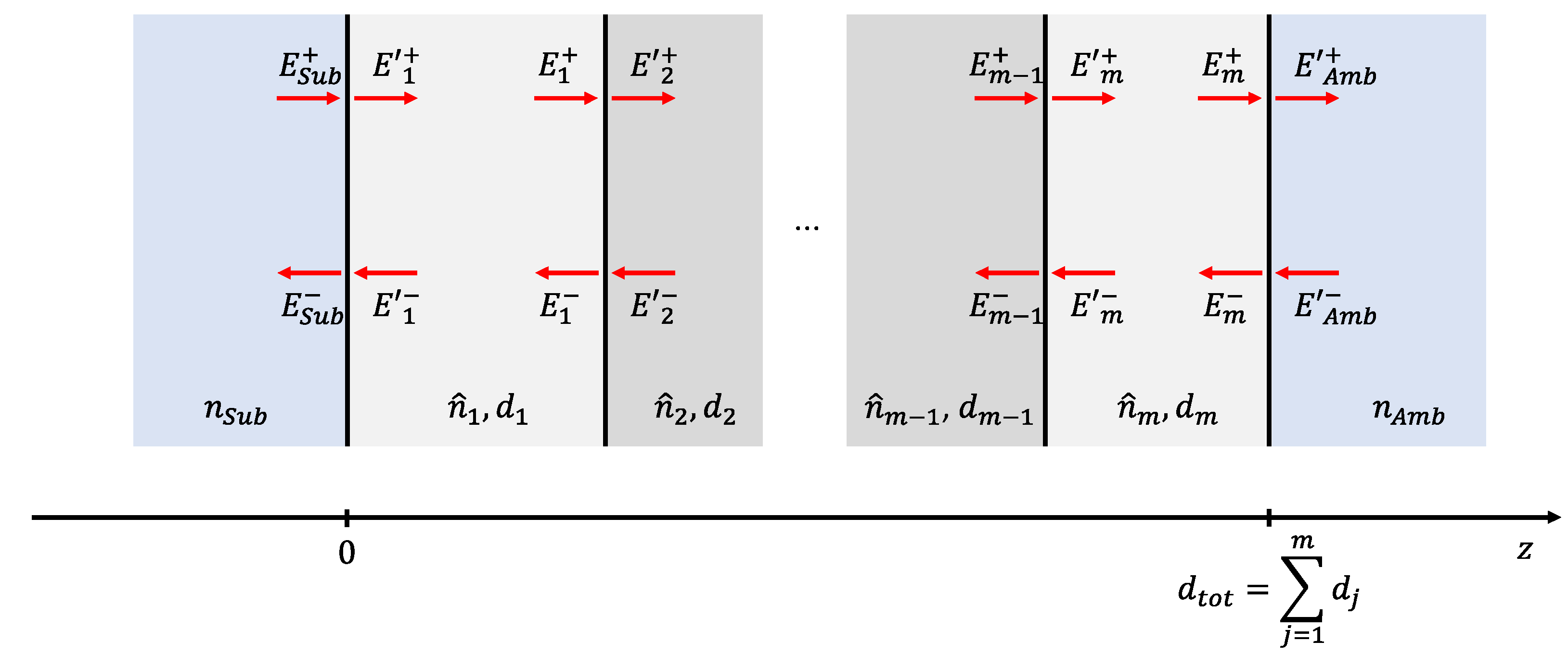
Figure 2.
Electric field strength ((a) and (b)) and refractive index profile((c) and (d)) of both type of conventional V-coatings.
Figure 2.
Electric field strength ((a) and (b)) and refractive index profile((c) and (d)) of both type of conventional V-coatings.
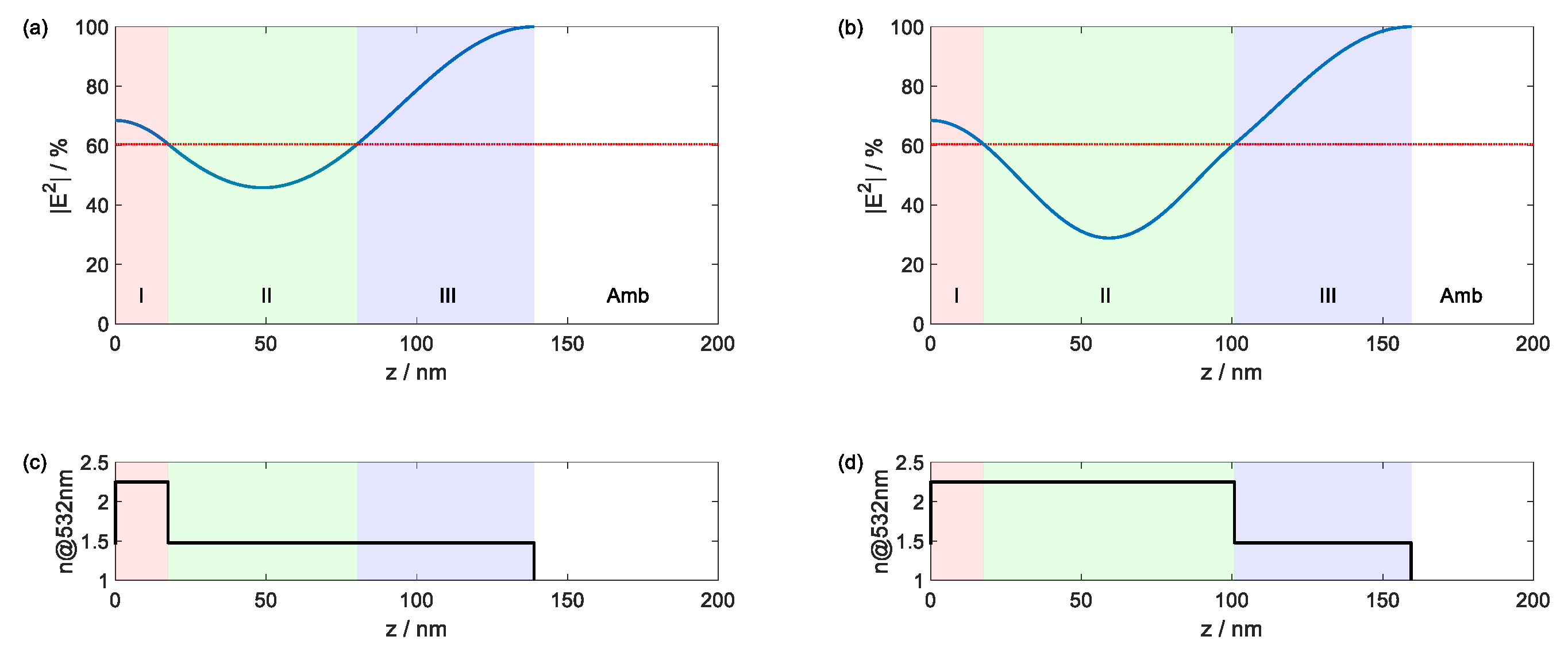
Figure 3.
Feasible range (in green) of refractive indices for a single wavelength double-layer antireflection coating at normal incidence (adapted Schuster-plot [22]). Refractive index combinations in white areas do not provide complete antireflection. Areas highlighted in red and yellow provide antireflection, but the necessary refractive indices are hardly found in nature when the substrate index is around 1.5.
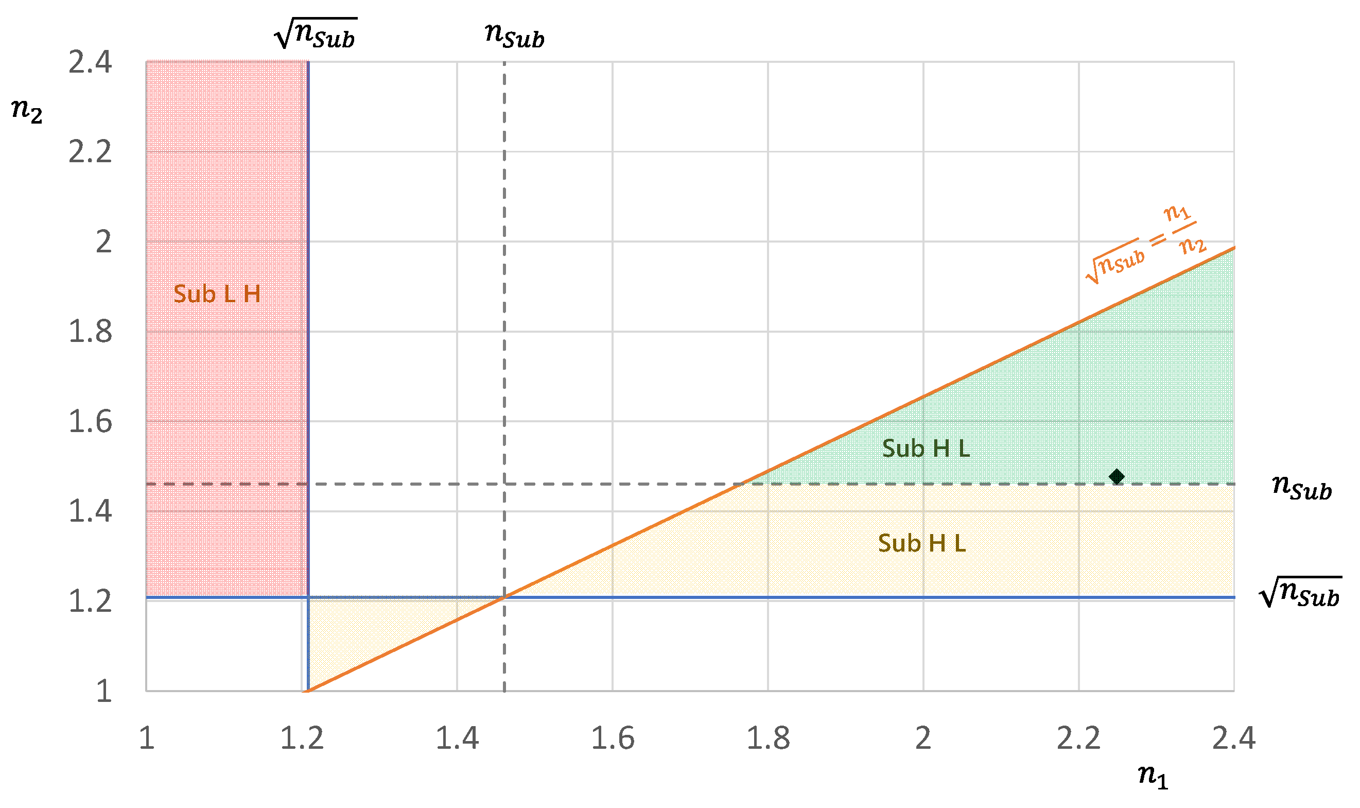
Figure 4.
Conventional antireflective coatings with increased layer number, where the Section II of the V-coating in Figure 2 is replaced by a symmetric layer sequence LHL (a) or HLH (b). Dashed lines indicate the interface positions of the symmetric layer sequence.
Figure 4.
Conventional antireflective coatings with increased layer number, where the Section II of the V-coating in Figure 2 is replaced by a symmetric layer sequence LHL (a) or HLH (b). Dashed lines indicate the interface positions of the symmetric layer sequence.
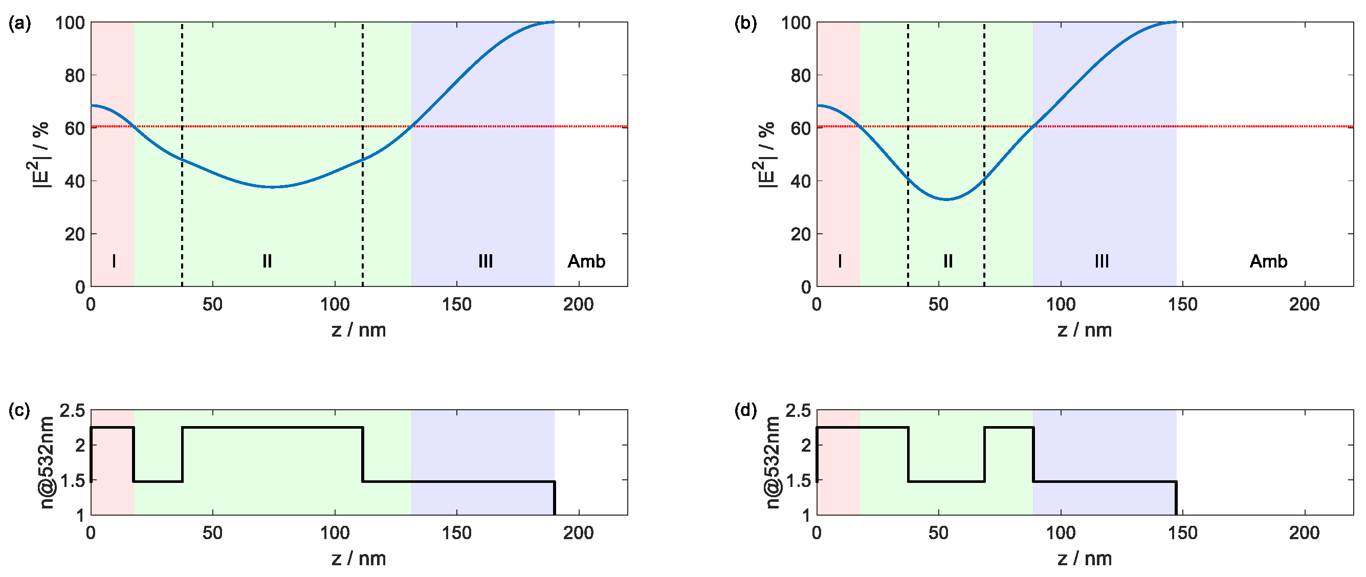
Figure 6.
Logarithmic presentation of reflectance (a) and (c) and transmittance (b) and (d) of two layers coatings for different layer thicknesses for 109 W/cm2.
Figure 6.
Logarithmic presentation of reflectance (a) and (c) and transmittance (b) and (d) of two layers coatings for different layer thicknesses for 109 W/cm2.
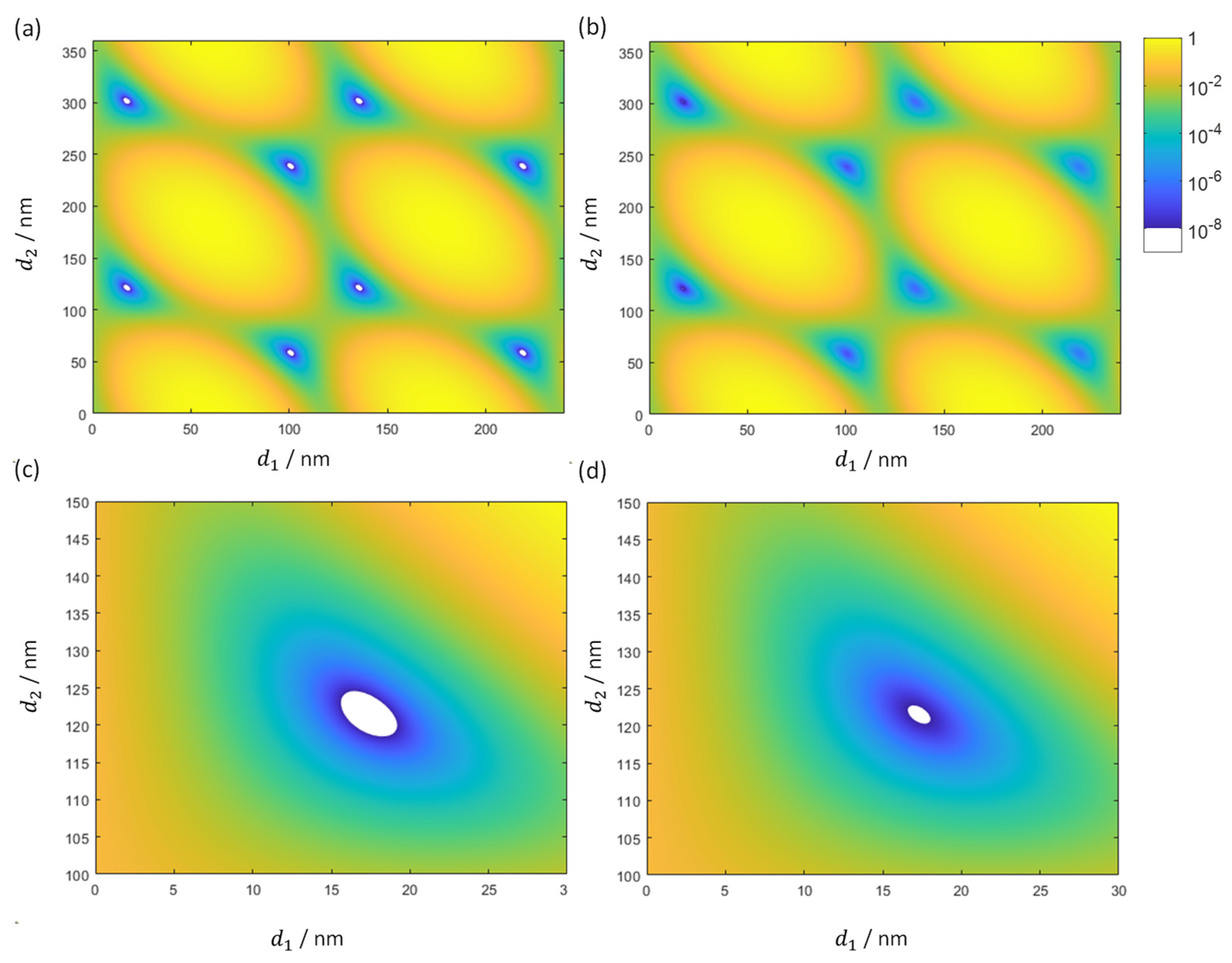
Figure 7.
Logarithmic presentation of reflectance (a) and (c) and transmittance (b) and (d) of two layers coatings for different layer thicknesses for 1011 W/cm2.
Figure 7.
Logarithmic presentation of reflectance (a) and (c) and transmittance (b) and (d) of two layers coatings for different layer thicknesses for 1011 W/cm2.
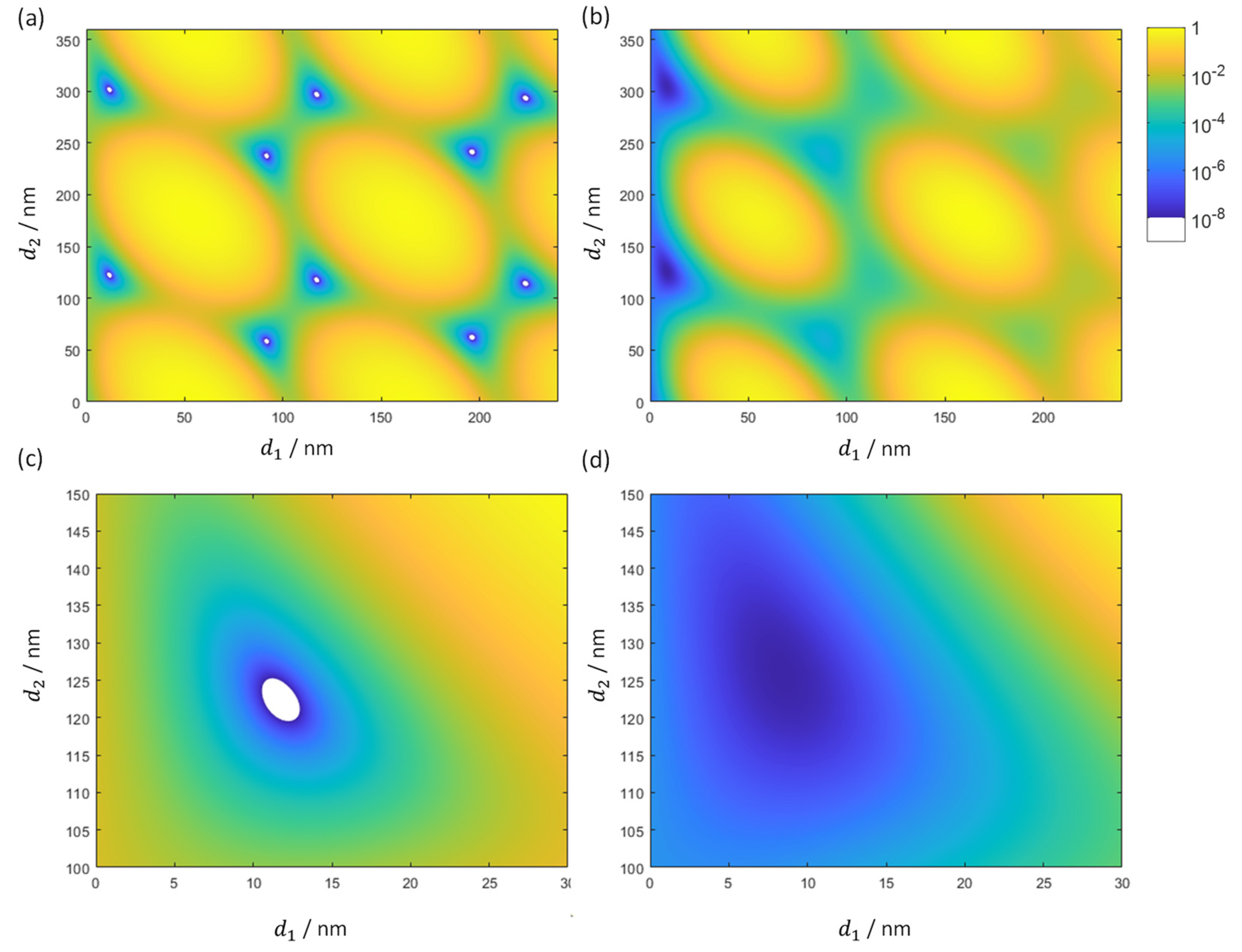
Figure 8.
Thickness combinations for a symmetrical three-layer system resulting in an equivalent refractive index of 1.
Figure 8.
Thickness combinations for a symmetrical three-layer system resulting in an equivalent refractive index of 1.
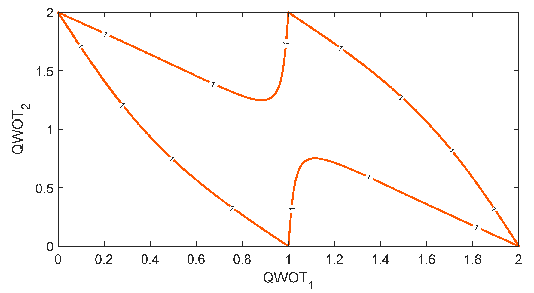
Figure 9.
Dependence of the calculated reflectance from maximum allowed slice thickness for a conventional V-Coating for 532 nm at 1011 W/cm2 (a) and 1012 W/cm2 (b).
Figure 9.
Dependence of the calculated reflectance from maximum allowed slice thickness for a conventional V-Coating for 532 nm at 1011 W/cm2 (a) and 1012 W/cm2 (b).
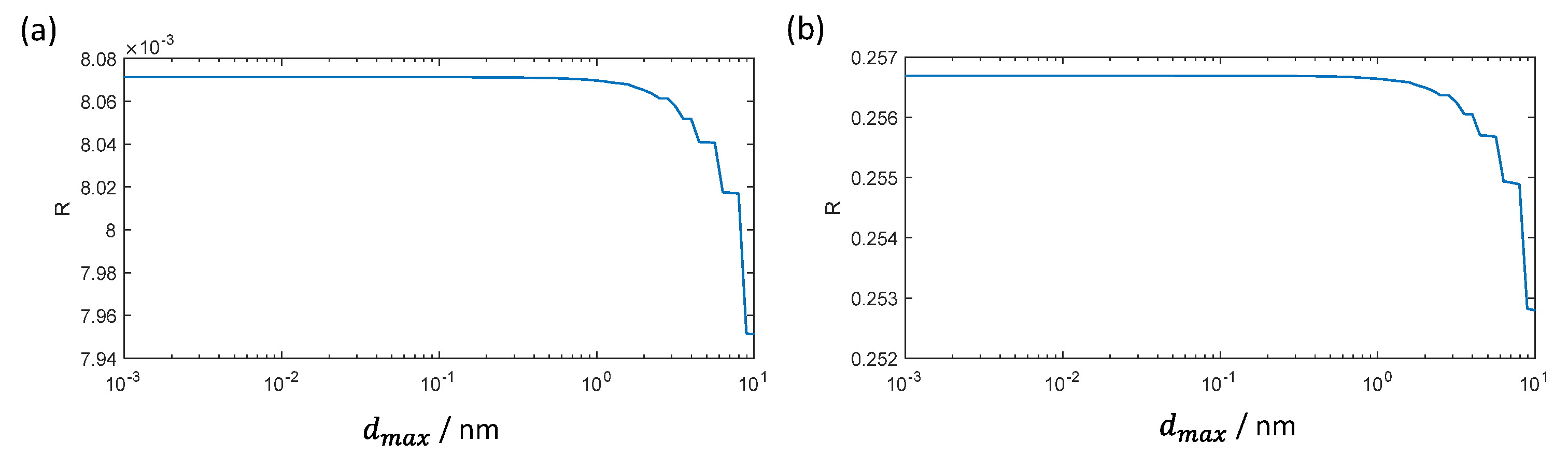
Figure 10.
Interim values during iterative calculation of a conventional V-Coating for 532 nm at 1011 W/cm2 (a) and 1012 W/cm2 (b).
Figure 10.
Interim values during iterative calculation of a conventional V-Coating for 532 nm at 1011 W/cm2 (a) and 1012 W/cm2 (b).
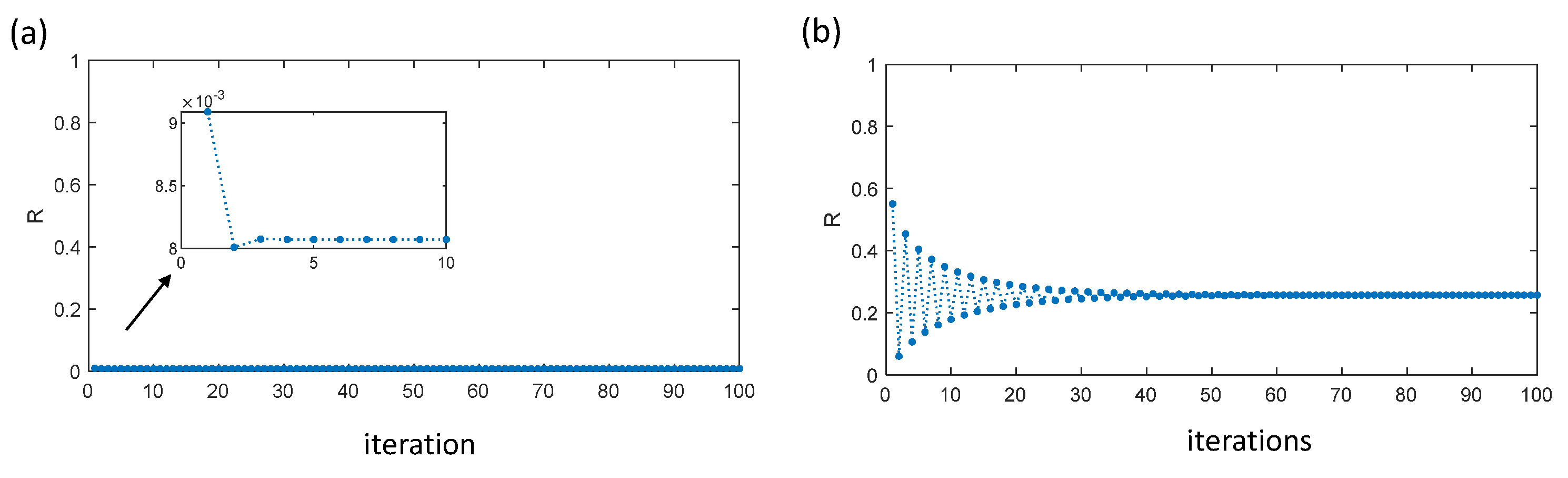
Figure 11.
Reflectance (a) and transmittance of a conventional V-coating (black) and optimized designs for minimum reflectance (red) and maximum transmittance (green) at 1011 W/cm2.
Figure 11.
Reflectance (a) and transmittance of a conventional V-coating (black) and optimized designs for minimum reflectance (red) and maximum transmittance (green) at 1011 W/cm2.
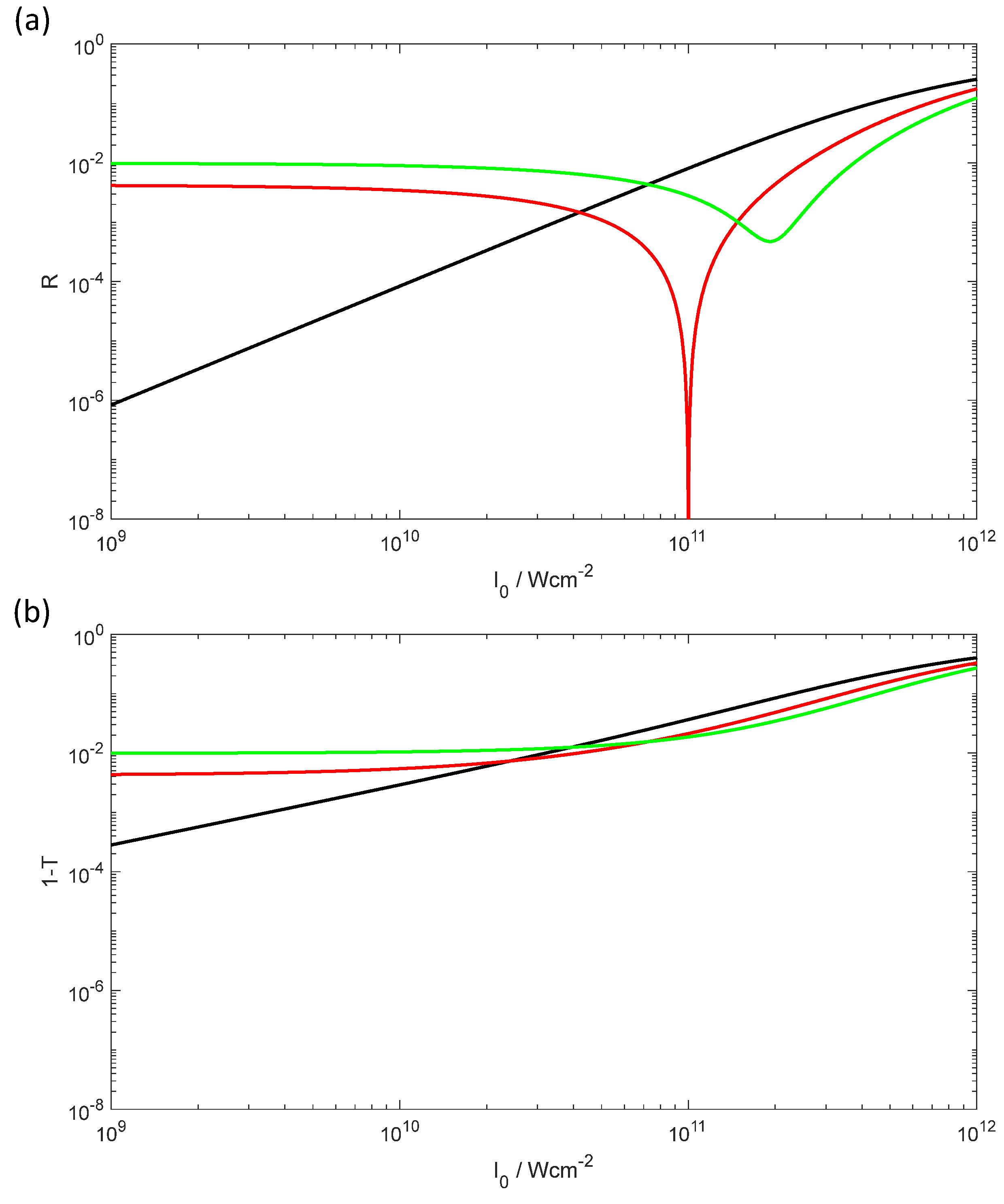
Figure 12.
Conventional V-Coating (left column) and optimized design (right column) for minimum reflectance at 1011 W/cm2 for 532 nm wavelength at different intensities: 1011 W/cm2 (blue) and 1012 W/cm2 (red) (a) and (b): normalized electric field strength, (c) and (d): effective refractive index, (e) and (f) effective extinction coefficient.
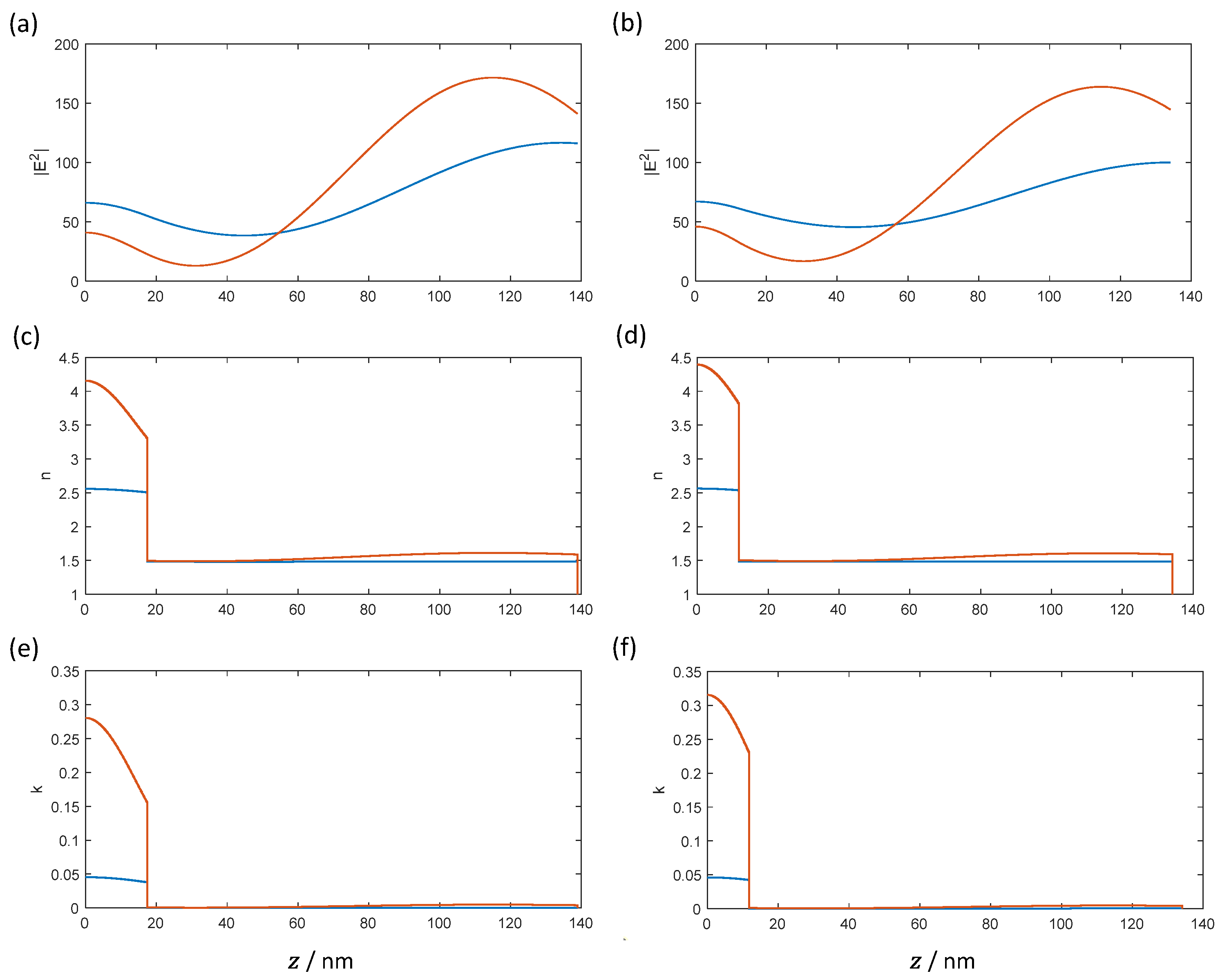
Figure 13.
Reflectance of a 4-layer normal incidence AR-coating optimized for intensities 109 W/cm2 and 1011 W/cm2.
Figure 13.
Reflectance of a 4-layer normal incidence AR-coating optimized for intensities 109 W/cm2 and 1011 W/cm2.
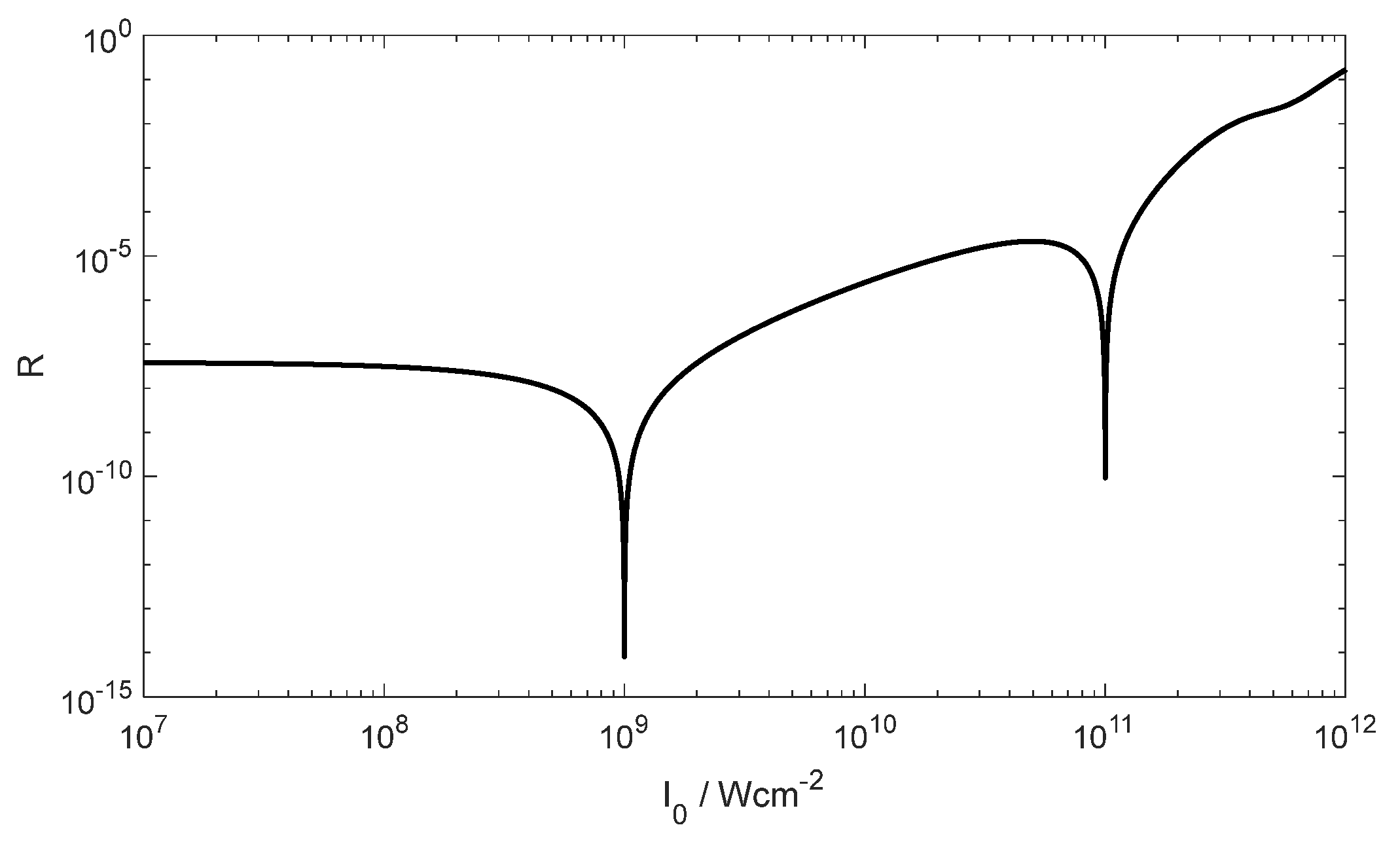
Figure 15.
Reflectance (left column) and electric field strength distribution (right column) of normal incidence AR-coating optimized for intensities in the range from 109 W/cm2 (orange line) to 1011 W/cm2 (blue line).
Figure 15.
Reflectance (left column) and electric field strength distribution (right column) of normal incidence AR-coating optimized for intensities in the range from 109 W/cm2 (orange line) to 1011 W/cm2 (blue line).
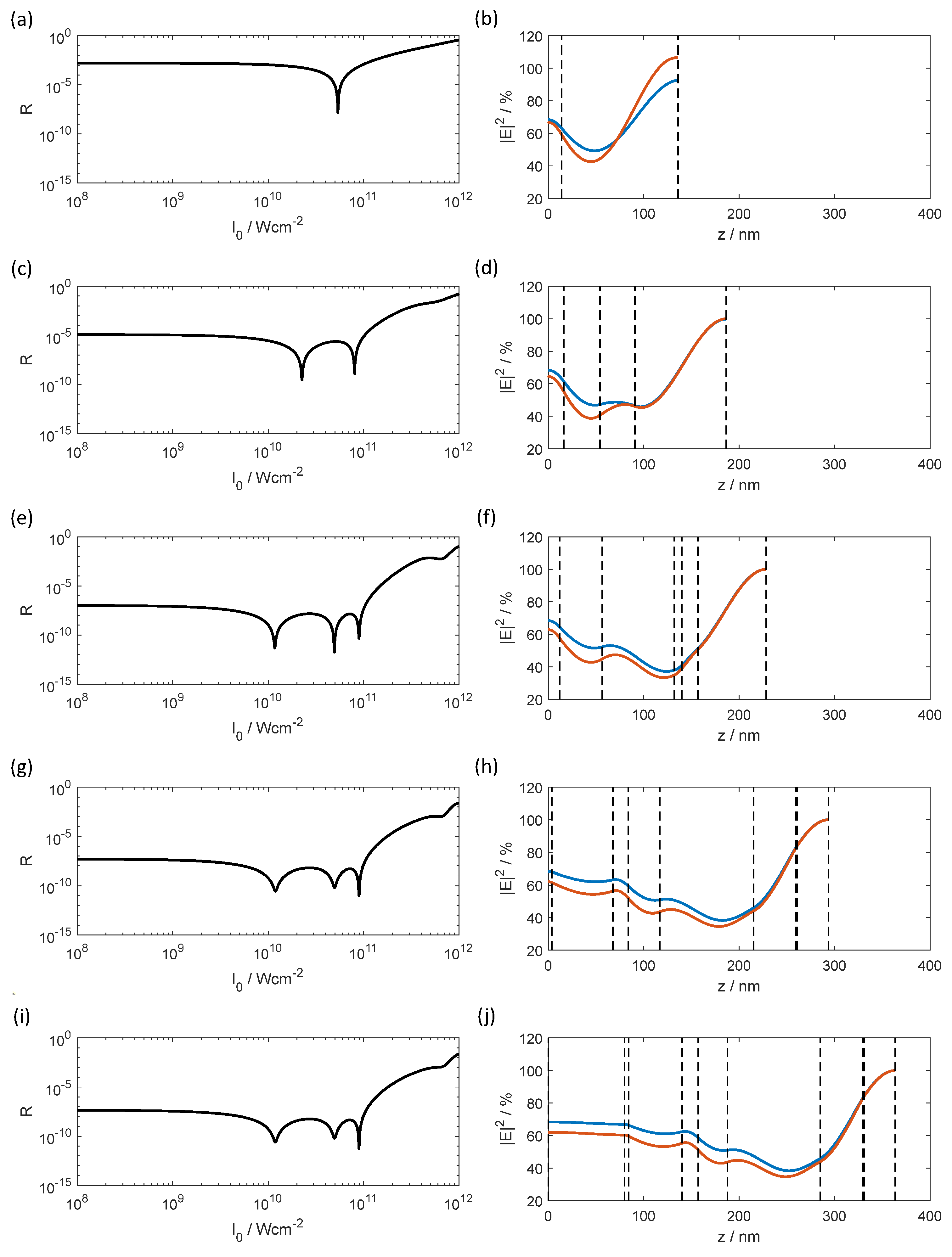
Figure 16.
Dependency of the discrepancy function of the average reflected intensity from the underlying number of layers for designs from Table 4.
Figure 16.
Dependency of the discrepancy function of the average reflected intensity from the underlying number of layers for designs from Table 4.
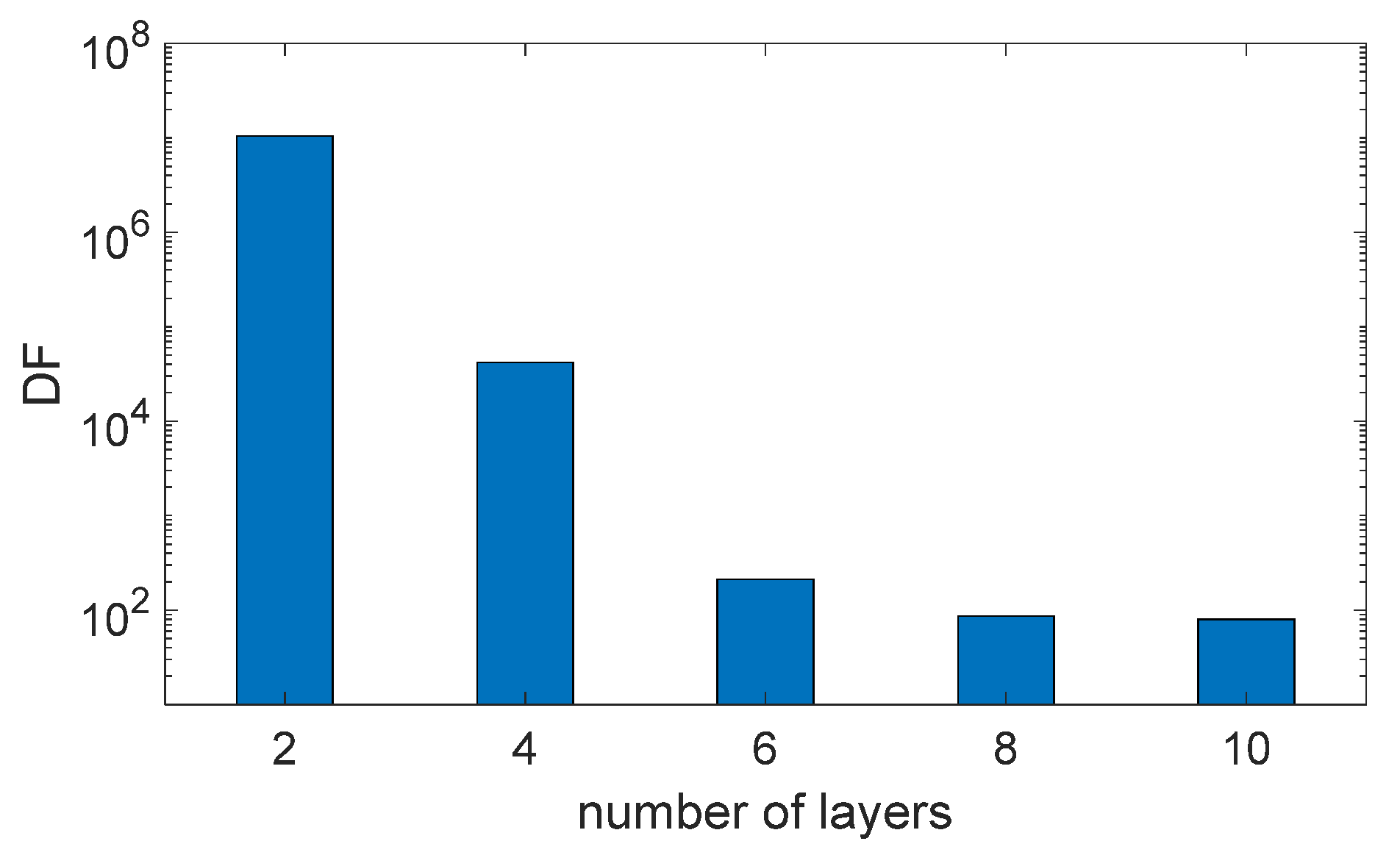

Table 1.
Assumed linear optical constants and and real and imaginary part of the cubic susceptibility of the underlying materials for the target wavelength 532 nm.
Table 1.
Assumed linear optical constants and and real and imaginary part of the cubic susceptibility of the underlying materials for the target wavelength 532 nm.
| Material | n | K | Re χ(3) / m2V−2 | Im χ(3) / m2V−2 |
|---|---|---|---|---|
| Substrate | 1.4607 | 0 | 0 | 0 |
| H | 2.249 | 0 | 1.86·10−20 | 2.74·10−21 |
| L | 1.477 | 0 | 2.05·10−22 | 7.32·10−24 |
| Ambient | 1 | 0 | 0 | 0 |
Table 2.
Layer thicknesses for the calculated 2-layer coating.
| Layer number |
Material | / nm | ||
|---|---|---|---|---|
| V-Coating |
R-Optimized Design (target ) |
-Optimized Design (target ) |
||
| 1 | H | 17.5 | 11.7 | 8.4 |
| 2 | L | 121.5 | 122.4 | 125.8 |
Table 3.
Layer thicknesses for the calculated 4-layer coating.
| Layer number | Material | / nm |
|---|---|---|
| 1 | H | 16.5 |
| 2 | L | 37.3 |
| 3 | H | 37.3 |
| 4 | L | 95.6 |
Table 4.
Layer thicknesses for the calculated design solutions.
| Layer number | Material | Number of layers | ||||
|---|---|---|---|---|---|---|
| 2 | 4 | 6 | 8 | 10 | ||
| / nm | / nm | / nm | / nm | / nm | ||
| 1 | H | 13.9 | 16.3 | 11.9 | 3.6 | 0.005 |
| 2 | L | 122.1 | 37.8 | 44.5 | 64.1 | 79.8 |
| 3 | H | 36.8 | 75.6 | 16.2 | 4.3 | |
| 4 | L | 95.6 | 7.9 | 32.8 | 56.1 | |
| 5 | H | 16.9 | 98.3 | 16.7 | ||
| 6 | L | 71.6 | 44.1 | 30.9 | ||
| 7 | H | 1.5 | 97.2 | |||
| 8 | L | 32.7 | 44.5 | |||
| 9 | H | 1.6 | ||||
| 10 | L | 32.3 | ||||
| Figure 15 | (a), (b) | (c), (d) | (e), (f) | (g), (h) | (i), (j) | |
Disclaimer/Publisher’s Note: The statements, opinions and data contained in all publications are solely those of the individual author(s) and contributor(s) and not of MDPI and/or the editor(s). MDPI and/or the editor(s) disclaim responsibility for any injury to people or property resulting from any ideas, methods, instructions or products referred to in the content. |
© 2025 by the authors. Licensee MDPI, Basel, Switzerland. This article is an open access article distributed under the terms and conditions of the Creative Commons Attribution (CC BY) license (http://creativecommons.org/licenses/by/4.0/).
Copyright: This open access article is published under a Creative Commons CC BY 4.0 license, which permit the free download, distribution, and reuse, provided that the author and preprint are cited in any reuse.


