
Submitted:
04 May 2025
Posted:
06 May 2025
You are already at the latest version
Abstract
Spherical tanks represent key infrastructure in the petrochemical industry, playing a vital role in the safe and efficient storage of a wide range of products. These products can range from highly volatile hydrocarbons such as liquefied petroleum gas (LPG) and liquefied natural gas (LNG) to various other chemicals essential for industrial processes. The very geometry of a sphere offers inherent advantages for such applications. Its uniform curvature allows for even distribution of internal pressure across the entire surface, making it an inherently strong and stable shape for containing pressurized fluids. This optimal stress distribution leads to the need for a thinner shell compared to other tank geometries for the same volume and pressure, potentially leading to material savings. Loads can arise from the internal pressure of the stored liquid, external factors such as wind and seismic activity, thermal gradients, and even localized loads at support points or connections. However, despite these advantages, spherical tanks are still susceptible to various external and internal loads that can cause stress and deformation.
Keywords:
spherical tanks
; petrochemical industry
; numerical simulation
; stresses
; deformation
; membrane
; internal gas pressure
; forces
; fem
; mathematical modeling
; measuring points
; experimental verification
0. Introduction
Understanding the magnitude and distribution of stresses and deformations that arise is paramount for several critical reasons. Excessive deformation can compromise the functionality of the tank, potentially affecting its capacity, the operation of connected equipment, and overall process efficiency. Predicting and mitigating deformations ensures long-term reliable operation. Precise stress and deformation analysis allows engineers to optimize the design of spherical tanks. This includes determining appropriate material thicknesses, weld configurations, and support structures to meet safety requirements while minimizing material usage and construction costs [1,2]. Understanding areas of high stress concentration or potential deformation can inform inspection protocols, enabling targeted non-destructive testing and early detection of potential issues, thereby preventing costly downtime and ensuring continuous safe operation. The petrochemical industry operates under stringent safety regulations and standards [3]. Comprehensive stress and deformation analysis, often validated experimentally, is crucial for demonstrating compliance and obtaining necessary certifications. By employing numerical simulation techniques, engineers can create detailed models to predict structural behavior under various loading conditions. Supplementing these simulations with experimental verification provides crucial validation of the numerical models, increasing confidence in their predictive capabilities and ultimately contributing to the safer and more efficient design and operation of these critical storage tanks [4,5,6]. In the numerical simulation of stresses and deformations in complex engineering structures, such as spherical tanks, the finite element method (FEM) is an indispensable tool. Figure 1 shows the distribution of equivalent stress values of a spherical tank using an FEM model in this work.
The continuous structure of the spherical tank is divided into a mesh of smaller, simpler elements (e.g., triangular or quadrilateral shell elements, or even three-dimensional solid elements for thicker sections or complex geometries like support connections). The material properties of the steel used for the tank (e.g., Young’s modulus, Poisson’s ratio, yield strength) are defined and assigned to these elements [7]. The tank supports are modeled by defining appropriate boundary conditions that restrict movement in certain directions. Different support configurations will influence the stress and deformation patterns. Various loads acting on the tank are applied to the model. This would primarily include the internal pressure exerted by the stored fluid, which is a critical design factor for pressure vessels. Other loads such as hydrostatic pressure (if the tank is partially filled), self-weight, and potentially external loads like wind or seismic forces (depending on the scope of your study and the tank’s location) would also be considered. The FEM software uses numerical algorithms to solve the system of algebraic equations derived from the principles of structural mechanics and the defined boundary conditions and loads [8]. These equations relate the displacements at the nodes of the elements to the applied forces. Once the displacements are calculated, the software can determine the deformation within each element using the element’s shape functions [9,10,11]. From the deformation, the stress distribution within the tank can be calculated using the material’s constitutive laws. Spherical shapes are relatively straightforward for FEM to model accurately compared to analytical methods that may require significant simplifications. FEM provides a comprehensive picture of the stress and deformation distribution throughout the tank structure, including areas of stress concentration that might be difficult to predict using analytical formulas alone (e.g., around support connections, nozzles, or welds). Numerical simulation allows for easy exploration of different loading scenarios, material properties, and design modifications without the need for expensive and time-consuming physical prototypes. For example, simulating the tank under different filling levels or with different support configurations. FEM software typically offers powerful visualization tools that allow you to see stress and deformation patterns through color-coded diagrams and animations, providing valuable insight into the structural behavior of the tank. Numerical simulation using FEM provides a theoretical prediction of stresses and deformations in a spherical tank under specific conditions. Experimental verification plays a crucial role in validating the numerical model. By comparing the results obtained from the FEM simulation (e.g., stress values at specific points, overall deformation patterns) with experimental measurements performed on a physical spherical tank (either in a scaled model or a full-scale tank), the accuracy and reliability of the numerical model can be assessed. Discrepancies between numerical and experimental results can highlight limitations in the FEM model, such as oversimplifications in geometry, material properties, boundary conditions, or loading [12]. This can lead to refinements of the numerical model to improve accuracy. A well-validated FEM model can be used with greater confidence to predict the structural behavior of similar spherical tanks under different operating conditions or design modifications, reducing the need for extensive physical testing in the future [13].
1. Mathematical Modeling
The state of stress in shell elements in the form of a rotating surface can be determined by the equilibrium equations for shell elements. The forces acting on an element that is part of a shell in the form of a rotating surface are shown in Figure 2. The element is defined by two parallel circles, with radii and , and two adjacent meridians determined by angles θ and θ+dθ. The position of the element belonging to the shell in the form of a rotating surface for a spherical tank is shown in Figure 2a, as well as the components of the external surface load X, Y, Z. The internal forces acting on this element are shown in Figure 2b [14,15,16]. The tank operates in moderate climatic conditions, so the influence of temperature can be neglected.
The equation represents the equilibrium of a small element of the spherical tank in the meridional direction
- - contribution of the change in the meridional membrane force to the equilibrium in the meridional direction
- - meridional membrane force per unit length in the spherical shell
- - is the meridional angle, measured from the pole of the sphere
- - represents the rate of change of the meridional membrane force with respect to the meridional angle
- - is likely the radius of curvature with respect to the meridional direction.
- - contribution of the in-plane shear membrane force to the equilibrium in the meridional direction .
- () - represents the in-plane shear membrane force per unit length in the spherical shell. This force acts in the plane of the shell, with one component along the meridional direction and the other along the circumferential direction.
- s the circumferential angle (or longitudinal angle)
- suggests a component of the shear force acting in the meridional direction due to curvature.
- - represents the rate of change of the circumferential component of the in-plane shear membrane force with respect to the circumferential angle. This term represents the contribution of the change in the in-plane shear membrane force to the equilibrium in the meridional direction.
- - presents the other radius of curvature which relates to the circumferential direction. For a sphere,=.
- - represents the external force per unit area acting on the spherical shell in the meridional direction.
Equation of change in internal forces (shear and normal) along the meridional and circumferential directions with external loading acting on the element:
- - shear force acting on a surface element of a spherical tank
- - rate of change of the resultant shear force with respect to the circumferential angle
- - radius of curvature of the spherical tank in the meridional direction
- - normal force acting in the circumferential direction on the surface element.
- = r \sin - radius of the parallel circle at a given meridional angle
- - normal force acting in the meridional direction on the surface element
- rate of change of the product of the meridional normal resultant (Nφ) and the radius of the parallel circle (Rsinφ) with respect to the meridional angle (φ)
- represents the external force per unit area acting on the surface of the spherical tank. The direction of this force is determined based on the overall equilibrium equation.
- - this product refers to a surface element on the surface of the spherical tank in spherical coordinates
The membrane equilibrium equation in the radial direction for a thin-walled spherical tank subjected to internal or external pressure.
- - resultant circumferential membrane force. It is a force per unit length acting in the tangential direction along the parallel circle of the sphere
- - radius of curvature in the circumferential direction. For a perfect sphere, () it is equal to the constant radius of the sphere, which is denoted as ( and therefore ( = = )
Total vertical component of the meridional membrane forces
Figure 3.
Equilibrium of the shell section.
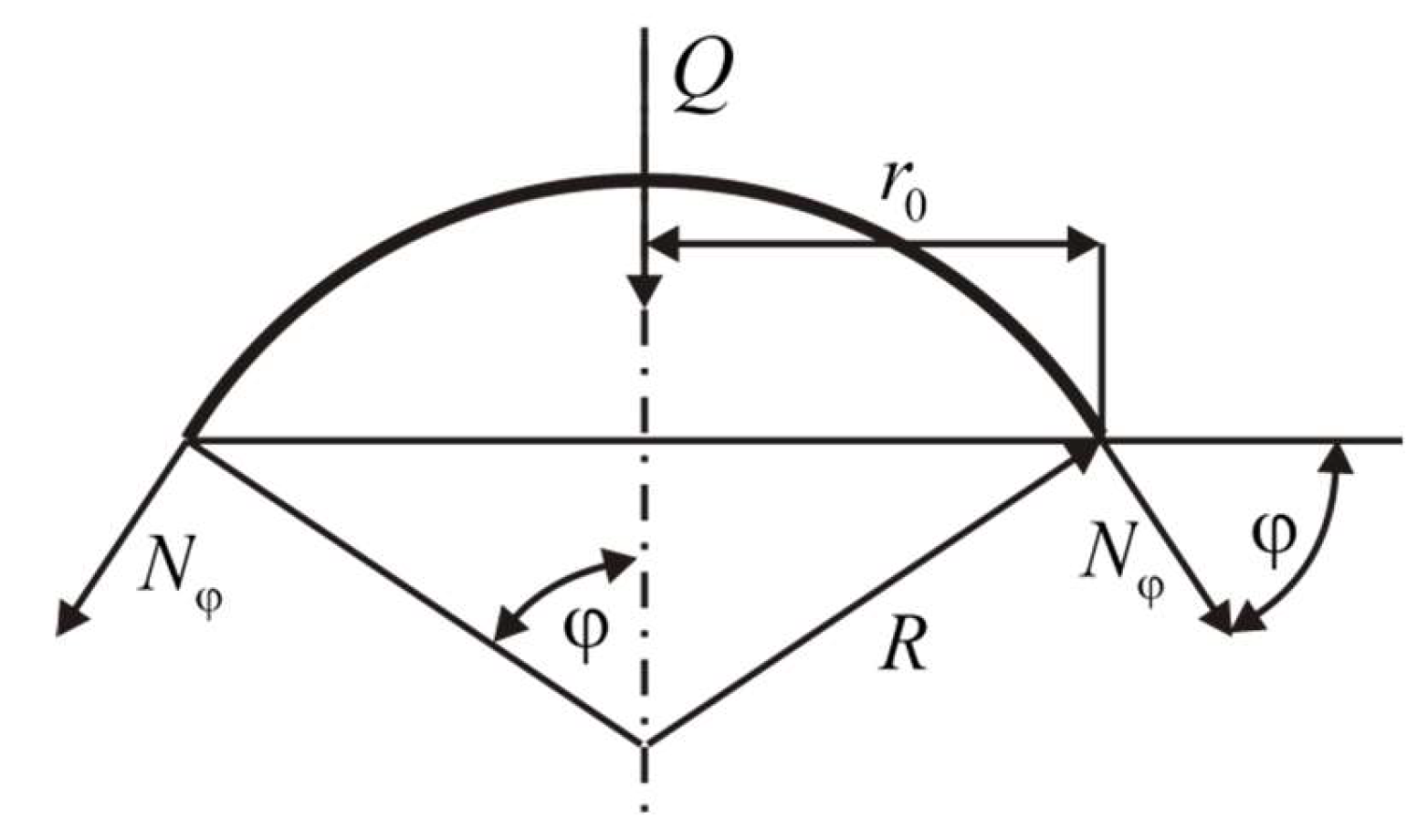
- circumference of the parallel circle on the sphere at a meridional angle φ
Equation (4) represents the external vertical force acting on the portion of the spherical tank above (or below) the parallel circle at an angle (φ) [17,18]. This force can be a result of the weight of the fluid in the tank up to that level, the weight of the tank material itself, or other external loads. Putting it all together, it expresses the equilibrium of vertical forces for the part of the spherical tank bounded by the apex(or bottom) and the parallel circle at an angle (φ). It states that the total vertical component of the internal meridional membrane forces must balance the external vertical force (Q) [19].
Figure 4.
Membrane forces (Nφ) at a specific angle (φ) if the external vertical load (Q) is known.
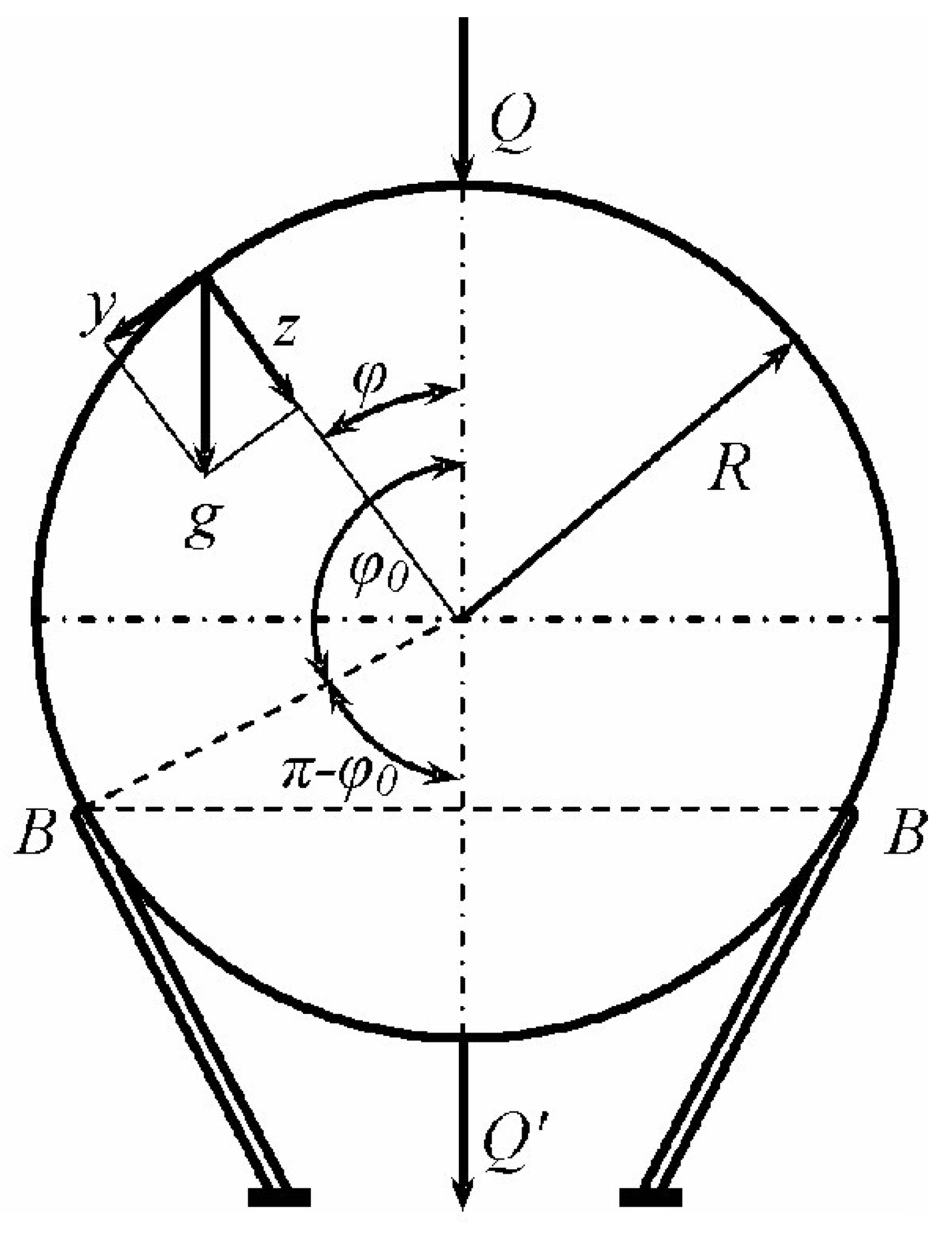
- - resultant meridional membrane force, which represents the force per unit length acting tangentially along the meridian,
- - acceleration due to gravity,
- - radius of the spherical tank,
- - meridional angle (φ), which is usually measured from the top or bottom pole of the sphere.
- - this term in the denominator shows how the meridional force varies with the angle (φ)
The negative sign in front suggests that the meridional force is compressive. This makes sense because the weight of the material above a certain part of the sphere will tend to compress the material along the meridian to support it.
Formula (5) states that the meridional membrane force at a given meridional angle (φ) is:
- a)
- proportional to the weight per unit area of the tank material (implicitly through (g)) and the density of the material, which is assumed constant and built in. Heavier material will result in higher internal forces. It is proportional to the tank radius (R). Larger tanks will generally experience higher membrane forces due to the increased material weight. At the top of the tank (φ = 0), (cosφ = 1), so . The compressive force is finite at the top. It is inversely proportional to (1+cosφ). It is shown how the meridional force changes with the angle (φ). As the angle (φ) increases towards the supports (which would be at some angle (φ < π/2) if the tank were supported around a circular base), the value of (cosφ) decreases, and (1+cosφ) also decreases, leading to an increase in the magnitude of the meridional pressure force) (). If we were to theoretically consider the equator (φ = π/2), (cosφ = 0) and (= - gR). As (φ) approaches (π) (the lower pole), (cosφ) approaches -1, and the denominator (1+cosφ) approaches 0. This suggests a theoretical singularity in the lower hemisphere if the weight of the entire sphere is taken into account and if there are no supports to directly take the load. However, in a real supported tank, this region would not be part of the “above the supports” consideration in the same way.
- b)
- Formula (5) specifically gives the meridional component of the internal membrane forces that are necessary to maintain equilibrium with the weight of the portion of the spherical tank material located above the parallelogram defined by the angle (φ). As we move down the tank (increasing (φ) this portion becomes larger and heavier, requiring greater internal compressive forces along the meridian to support it. To get a complete picture of the internal forces, one should also determine the circumferential (rim) membrane force () under this loading condition. The analysis of a spherical shell under its own weight usually involves solving the membrane equilibrium equations in both the meridional and circumferential directions. This formula provides a distribution of the meridional membrane compression force in a spherical tank due to the weight of the material over a given latitude, characterized by the angle (φ). The force increases as we move towards the supports (increasing (φ) reflecting the need to support more weight.
- - is the resultant of the circumferential (or hoop) membrane force. It is the force per unit length acting tangentially along a parallel circle at an angle (φ).
- g - Acceleration due to gravity.
- R - Radius of the spherical reservoir.
- φ - Meridional angle, usually measured from the top pole.
- 1/(1+cosφ) - This term is related to the meridional force distribution we saw earlier.
Formula (6) shows that the circumferential membrane force at a given angle (φ) is affected by two parts:
- -gRcosφ - This part suggests the contribution related to the vertical component of the meridional forces and the geometry of the sphere.
- (cosφ) denotes how the angle affects this contribution. At the top (φ = 0), (cosφ = 1), which leads to a compressive contribution. As (φ) increases, (cosφ) decreases, reducing this compression effect and potentially leading to tension at larger angles.
- gR/(1+cosφ)) - This part is directly related to the meridional force (). Since (= -gR/(1+cosφ)), the term gR/(1+cosφ) can be written as (-). It represents the contribution of the meridional tension (or compression) acting around the parallel circle, which has a radial component that needs to be balanced by the hoop stress.
The combination of these two terms determines whether the circumferential force () is tensile or compressive at a given angle (φ).
The circumferential force at the top is compressive and equal to the meridional force.
As (φ) increases: The behavior of () becomes more complex as (cosφ) decreases. The first term (-gR cosφ) becomes less compressive (or even tensile), while the second term (+gR 1/(1+cosφ)) (which is () becomes more compressive (since () is compressive and its magnitude increases).
Around supports (at some angle φ < π/2): The value of () will depend on the specific angle of the support. It is possible for () to change sign (from compressive to tensile) depending on the geometry and self-weight distribution.
The force due to the greater self-weight of the tank above the supports emphasizes that the internal forces, both () and (), arise from the need to support the weight of the tank material above the level considered (defined by (φ)). As we move down the tank, the amount of material above increases, resulting in a greater load that must be carried by the internal membrane forces [20,21,22]. The specific shape of () reflects how this weight is distributed and resisted in the circumferential direction, taking into account the meridional forces and the curvature of the shell.
In short, the formula for () gives the force distribution of the circumferential membrane in a spherical tank under its own weight above the supports. Its shape indicates a balance between geometric effects and the contribution of meridional forces, resulting in a stress state that varies with the meridional angle (φ). Understanding both () and () is crucial for the structural analysis and design of spherical tanks.
Formula components (7):
- - Resultant of the circumferential (rim) membrane force.
- - Acceleration due to gravity.
- - Radius of a spherical tank.
- - Meridional angle, usually measured from the upper pole (0 to π).
- - cosine of the meridional angle.
- () : This term will have a significant impact on the behavior of () with the variable (φ).
Formula (7) now suggests that the force of the circumferential membrane is affected by:
- ( ) - contributing to the pressure at the top (φ approximately 0)) and moving towards tension as (φ) increases.
- (+ ) - As (φ) approaches 0 (the top of the tank), (cosφ) approaches 1, and the denominator (1-cosφ) approaches 0. This means that the magnitude of this term will become very large and positive, indicating a large tensile bulk force near the top. This is in stark contrast to the previous formula where () was compressive at (φ = 0).
As (φ) increases, (cosφ) decreases, and the denominator (1-cosφ) increases, causing the magnitude of this positive term to decrease.
At (φ = π/2) (the equator), (cosφ = 0), and the term becomes (gR 1/(1-cosφ)) = gR.
As (φ) approaches (π) (the lower pole), (cosφ) approaches -1, and the denominator (1-cosφ) approaches (1 - (-1) = 2), the term (gR 1/(1-cosφ)) approaches 1/2 gR
At the top of the tank (φ approximately 0): The term (gR 1/(1-cosφ)) dominates and becomes very large and positive, indicating a large tensile bulk force. This is a critical difference from the previous formula.
As (φ) increases: the value of () will be determined by the balance between the -gRcos term (which initially tends to be compressive) and the (+gR/(1-cosφ)) term (which is tensile and decreases in size). There will come a point where () changes sign.
The behavior near the support will depend on the specific angle of support and will differ from the previous case due to the modified formula.
Similar to the previous case, this formula aims to capture the circumferential forces resulting from the need to support the weight of the tank material above a given latitude. However, the form of this equation suggests a different way in which these loads are distributed and resisted in the circumferential direction [23]. The singularity at (φ = 0) is particularly noteworthy and may indicate a specific type of support condition or a different set of assumptions in the derivation of this formula compared to the previous one.
The (1-cosφ) term in the denominator often occurs when considering geometries or force resolutions that are related to the distance from the pole or a specific axis. This particular pattern can occur if:
The meridian angle (φ) is defined differently (e.g., from the bottom pole instead of the top). However, the standard convention is from the top.
There are specific boundary conditions or support mechanisms at the top of the tank that cause the tension hoop.
The weight distribution or the way the load is transmitted through the shell is modeled differently.
The formula =-gR(cosφ- 1/(1-cosφ)) predicts a significantly different distribution of the bulk membrane forces compared to the previous formula, especially near the top of the tank where it suggests a large tension force. This difference arises from variations in the assumed loading conditions, support mechanisms, or the coordinate system used in the derivation.
- p=-Z – shows that the total pressure (p) is equal to the negative value of the external load per unit area (Z). In the context of a pressure vessel, the negative sign usually means that (Z) represents the internal pressure acting externally on an element of the vessel’s surface. Therefore, (p) is the internal pressure.
- γR (1-cosφ) - represents the hydrostatic pressure in the fluid at a depth corresponding to the meridian angle (φ).
- γ - specific gravity of the liquid (density times gravity, (γ=ρgh_0).
- R - radius of the spherical tank.
- (1 - cosφ) - a factor that determines the depth of the liquid depending on the angle (φ), usually measured from the top of the tank. When (φ= 0) (top), (1 - cos 0 = 1 - 1 = 0), so the hydrostatic pressure is zero. As (φ) increases, (cos φ) decreases, so (1 - cos φ) increases, which means that the depth increases, and therefore the hydrostatic pressure. At the bottom of the tank (φ = π), (1 - cos π = 1 - (-1) = 2), so the hydrostatic pressure is maximum and is (2γR) (if the tank is full to the bottom).
- - This part represents the uniform pressure that is superimposed (added) to the hydrostatic pressure. “Uniform” means that this pressure that is constant over the entire surface of the tank and does not depend on the meridian angle (φ). This pressure may come from the gas above the liquid in the tank or from some other external uniform load.
Adding these components gives the total internal pressure (p) at any point in the spherical tank defined by the angle (φ).
In short, the formula (p=-Z=γR(1-cosφ)+ ) describes that the total internal pressure on a spherical tank is composed of two parts:
The hydrostatic pressure of the liquid, which varies with depth (and therefore with angle (φ), and
The uniform pressure, which is constant over the entire internal surface of the tank.
This formula is important for analyzing the stresses and strains in the walls of a spherical tank under the action of an internal pressure that is not only hydrostatic, but also has a constant component. Using this formula for (p) (or (-Z)), the equilibrium equations can be further solved.
In the context of a spherical tank, the formula refers to the bearing capacity or stability analysis of a spherical tank foundation.
- γ -represents the unit weight of the soil supporting the spherical tank.
- R -represents the radius of the spherical tank
- φ - the angle of internal friction of the soil under the tank foundation.
- - the internal gas pressure inside the spherical tank.
- - refers to the shear strength properties of the soil and how they contribute to the bearing capacity under the load imposed by the tank.
- - involves the internal gas pressure of the tank and its radius. The factor 2 directly multiplied by the radius suggests that this could be related to the increasing force or stress distribution caused by this internal pressure acting on the tank foundation or supports.
Hydrostatic pressure for a spherical tank is primarily relevant in two ways:
The pressure exerted by any liquid contents within the tank: If a spherical tank is filled with liquid, the pressure at any point within the liquid (and therefore on the inside surface of the tank) will depend on the depth of the liquid at that point and the density of the liquid. This internal hydrostatic pressure acts outwardly on the tank walls [24].
Pore water pressure in the supporting soil: If the foundation of a spherical tank is below the water table, the soil pores will be filled with water, exerting hydrostatic pressure. As mentioned earlier, this pore water pressure affects the effective stress in the soil, which in turn affects the bearing capacity.
Internal gas pressure : This refers to the pressure exerted by any gas contained within the spherical tank.
The internal gas pressure inside the tank will exert an outward force on the tank walls. This force will be transmitted through the tank structure to its supports and then to the foundation. The term in the formula suggests that this internal gas pressure contributes to the total bearing demand on the soil. A higher internal gas pressure would likely increase the foundation load.
Formula (10) can be used to determine a factor tht, when multiplied by other bearing capacity terms (such as cohesion and fill), gives the ultimate bearing capacity of the soil beneath the spherical tank [25]. The inclusion of the term internal gas pressure indicates that the force or stress caused by this pressure is taken into account in the stability analysis.
Hydrostatic pressure can be relevant both internally (from the liquid content) and externally (as the pressure of water in the soil pores), only the effects of internal gas pressure are directly included in the given formula (10).
The internal gas pressure () inside the spherical tank exerts an external force, increasing the load transmitted to the foundation, which is reflected in the term .
- - represents the hoop force or circumferential normal force in a structural element at a given angle φ. It is a measure of the tension or compression acting along the circumference.
- - denotes the specific gravity (weight per unit volume) of the fluid exerting hydrostatic pressure. If the structure is submerged in water, γ would be the specific gravity of the water.
- - represents the radius of curvature of the structural element (assuming it is curved, such as an arch or cylindrical shell).
- φ - is an angular coordinate that defines the location on a structural element where the internal force is calculated. It is usually measured from a reference point, often a crown or support.
- ⌊ ⌋ - The expression enclosed in the floor function symbols (although it may be just regular parentheses depending on the context) represents the distribution of the hoop force due to hydrostatic pressure as a function of the angle φ. The trigonometric functions (cosφ) show how the depth, and hence the hydrostatic pressure, varies with angle. The term (1+cosφ) in the denominator, which suggests the angle φ is measured from above or below where cosφ = − 1 may be a special case.
- - represents the internal gas pressure acting above the support. This pressure is uniform in the area it acts on.
- This expression represents the contribution of the internal gas pressure to the hoop force. It is the direct tensile force caused by the internal pressure acting on the curved surface. It directly gives the force per unit length (the hoop force ).
The formula essentially calculates the total hoop force () at a specific angular location (φ) in the structure by adding two contributions:
- represents the hoop force resulting from the hydrostatic pressure exerted by the fluid. The magnitude of this force depends on the specific gravity of the fluid (γ), the geometry of the structure (radius R), and the angular position (φ). A complex trigonometric function captures the uneven distribution of hydrostatic pressure with depth [26]t.
In simpler terms, the formula tells how much volumetric tension or compression exists at various points in a curved structure (such as a submerged arch or a pressurized tank with a specific geometry) due to the combined effects of the weight of the fluid pressing on it and the pressure of any gas trapped inside above the water level.
Directly gives the force per unit length (the hoop force).
Key differences and similarities compared to the previous formula:
- - This term describes the distribution of the meridional force due to hydrostatic pressure as a function of the angle φ. The form of this expression reflects how hydrostatic pressure and geometry contribute to the forces in the meridional direction. 1-cosφ , in the denominator suggests that the forces could become very large near the bottom (if φ is measured from the top)
- - represents the contribution of internal gas pressure to the meridional force . Similar to the hoop force, it adds a tension component due to internal pressure.
Formula (12) calculates the total meridional normal force () at a specific angular location (φ) in the structure, taking into account the combined effects of the hydrostatic pressure from the fluid below the support and the pressure of any gas trapped inside below the support.
The change in the trigonometric term, especially the denominator 1-cosφ, strongly suggests a different physical scenario compared to the first formula. This could imply:
A submerged structure where the angle φ is measured from the bottom. In this case, for φ = 0∘ (bottom only), cosφ=1, and the term can become very large, indicating high meridional forces at the lowest point due to hydrostatic pressure.
In short, formula (12) provides the meridional (or similar longitudinal) internal force in a curved structure that is subjected to hydrostatic pressure from below and internal gas pressure under the support.
The mathematical form indicates that the distribution of this force with angle φ is different from the hoop force and reflects the specific way in which these pressures act on the geometry in the meridional direction.
To gain a more precise understanding, knowledge of the exact geometry of the structure and the definition of angle φ would be very helpful.
Formula (13) deals with the analysis of internal forces in a structural element, a shell or arch, subjected to both hydrostatic pressure and internal gas pressure
- - represents the meridional normal force at a certain angle φ in the structural element.
- - this term is related to hydrostatic pressure.
- γ - this is typically the specific gravity of the fluid exerting the hydrostatic pressure (weight per unit volume).
- R- represents a characteristic linear dimension or radius associated with the structure. The fact that it is square suggests that it is associated with an area or distributed load.
The division by 6 is a geometric factor resulting from the integration of the pressure distribution over the area.
- - this dimensionless term is a function of the angle φ describing the distribution of the meridional normal force due to hydrostatic pressure along the structure.
- φ -This is the angle defining the location on a curved structure, measured from a reference
The cosine function shows that the force component varies with this angle.
The complexity of this expression arises from the geometry of the structure and the way in which hydrostatic pressure acts on its curved surface. The term probably originates from the integration of the pressure component along the meridian.
- - this term is related to the internal gas pressure .
- R- the characteristic linear dimension of the structure.
- - represents the internal gas pressure acting on the structure.
Formula (13) calculates the total meridional normal force () at a given angle (φ)
The first term includes the forces resulting from the pressure exerted by a fluid (such as water) acting on the submerged surface of the structure. This contribution depends on the specific gravity of the fluid (γ), the characteristic dimension of the structure (R), and the location on the structure defined by the angle φ.
The second term takes into account the forces resulting from the uniform internal gas pressure () acting on the internal surface of the structure. This contribution also depends on the characteristic dimension R,.
2. Finite Element Simulation and Experimental Verification
The finite element method was used to calculate a spherical tank with a volume of V=1000 m3, an outer diameter of D=12500 mm, and a wall thickness of δ=30 mm. The spherical tank is made of steel segments with a yield stress of:The working pressure in the tank is: =16.7MPa. Experimental testing was performed with water (γv=1000 N/m3 ) instead of a propane-butane gas mixture. Using expressions (7-13) and the expressions for stresses:
The corresponding values of forces and stresses for different angles are obtained. The total value of the stress can be calculated by adding the components of self-weight and internal pressure. The obtained values are shown in Table 1 and Figure 5.
For the purpose of creating the FEM model, a tetrahedral element with 10 nodes was selected. The 3D model of the spherical tank was formed by synthesizing the 3D models of all structural parts. The model represents a continuum of discredited (45124 nodes. 25016 elements). The equivalent stress field is shown in Figure 1. The distribution of equivalent stresses of the FEM analysis corresponds to the distribution of stresses obtained by analytical calculation.
The highest stress values were obtained at the support points of the spherical tank (Figure 6)
The deformations of the spherical tank are shown in (Figure 7). Since the FEM analysis identified hazards in the proposed design, experimental verification was required to be absolutely certain that the plastic deformations in the supports would not cause structural failure. These values are higher than the yield stress and may cause deformation of the tank supports. Since the area of this high stress concentration is very small, it is concluded that the overall strength of the supports will not deteriorate over time due to the accumulation of plastic deformation.
Experimental testing of the spherical tank was performed to verify the results of the analytical and FEM models. For safety reasons, the experiment was performed with water instead of a propane-butane gas mixture. Stress measurements were performed at 7 measurement points using the HBM UPM 100 measuring equipment. The arrangement of the measurement points is shown in Figure 8. and this type of strain gauge setup facilitates measurement and does not require knowledge of the direction of the principal stresses.
The strain gauges placed on spherical tank are shown in Figure 9.
3. Results and Discussion
Table 2 gives comparative stress values for a working pressure of 1.67 MPa obtained at characteristic points: analytically, by FEM model and experimentally.
Table 3 shows the deviation of the equivalent stresses obtained analytically and by the FEM model.
The experimentally obtained stress values for some measurement points are higher than the analytical or FEM calculated stress values in the point shown in Table 2, while for these 2 tables they have a lower value. The discrepancy requires experimental verification to ensure that the proposed design will meet all safety requirements. The equivalent stress values for the test pressure of 2.5 MPa are shown in Table 4, and the deviations from the results obtained analytically and using the FEM model in relation to the results obtained experimentally are shown in Table 5.
Compared to the experimental values in Table 3 and Table 5, it can be clearly seen that the FEM results are more accurate than the analytical results. FEM analysis is also much cheaper than prototype construction and testing, it can identify critical areas and, if necessary, design modifications are easily and quickly implemented. No further modifications to the tank design are required to verify the design. In the example of the analyzed spherical tank, the equivalent stress values at point MM4 were higher than the yield stress values, but not over the entire cross section (Figure 7). The areas of local plastic deformation associated with the stress concentrations are small enough so that there is no significant permanent deformation when the load is removed. The stress concentration predicted by FEM was also recorded by the experimental test. The design of the reservoir proved to be reliable, as the measured values of equivalent stresses after eight months of operation (Table 2 and Table 4) were identical to the original values after the installation of the spherical reservoir and its commissioning.
4. Conclusion
The methodology presented in this paper, which uses the advantages of analytical, numerical and experimental procedures, ensures fast design time, optimal dimensioning and, most importantly, safety in the envisaged operating conditions.
The conducted research has shown a high degree of correspondence of the results obtained analytically and by the FEM model with the results of experimental testing of spherical tanks. This correspondence of the results allows analytical expressions to be used for the dimensioning of spherical tanks. This is especially important because in a short period of time, in the initial design phase, the basic dimensions of a spherical tank can be obtained without performing experiments and without FEM modeling.
After the initial design phase, when all the dimensions of the tank are known, a more precise FEM analysis is used to identify areas of high stress concentration. In the case of the analyzed tank for a test pressure of 2.5 MPa, the equivalent stress exceeds the yield point at the points of connection of the tank with the supports. Given that this large stress is concentrated on a small area of the connection surface, the plastic deformations are small enough that we conclude that this stress value is not critical and that the construction of the spherical tank can continue.
After the construction of the spherical tank, the FEM results were verified by experiments. The experiments were repeated after 8 months, which confirmed the validity of the FEM conclusion that it is not necessary to strengthen the spherical tank at the points of its connection with the supports, despite the fact that minor plastic deformations occur.
Author Contributions
Conceptualization, H.O.S.A., V.D., J.Ž., N.T. and R.P.; methodology, H.O.S.A., V.D., J.Ž., N.T. and R.P.; software, H.O.S.A., V.D., J.Ž., N.T. and R.P.; validation, H.O.S.A., V.D., J.Ž., N.T. and R.P.; formal analysis, H.O.S.A., V.D., J.Ž., N.T. and R.P.; investigation, H.O.S.A., V.D., J.Ž., N.T. and R.P.; resources, H.O.S.A., V.D., J.Ž., N.T. and R.P.; data curation, H.O.S.A., V.D., J.Ž., N.T. and R.P.; writing—original draft preparation, H.O.S.A., V.D., J.Ž., N.T. and R.P.; writing—review and editing, H.O.S.A., V.D., J.Ž., N.T. and R.P.; visualization, H.O.S.A., V.D., J.Ž., N.T. and R.P.; supervision, J.Ž., N.T. and R.P.; project administration, J.Ž., N.T. and R.P.; funding acquisition, J.Ž., N.T. and R.P. All authors have read and agreed to the published version of the manuscript.
Funding
This research received no external funding.
Conflicts of Interest
The authors declare no conflicts of interest.
References
- Su, W.; Feng, X. Numerical Simulation of Failure Analysis of Storage Tank with Partition Plate and Structure Optimization. Mathematics 2021, 9, 3230. [Google Scholar] [CrossRef]
- Shiromani, R.; Shanthi, V.; Das, P. A higher order hybrid-numerical approximation for a class of singularly perturbed two-dimensional convection-diffusion elliptic problem with non-smooth convection and source terms. Computers & Mathematics with Applications. 2023, 142, 9–30. [Google Scholar]
- Chen, C.; Chen, H.; Mo, L.; Xiao, S.; Li, C.; Yang, M.; Reniers, G. Buckling failure analysis of storage tanks under the synergistic effects of fire and wind loads. Journal of Loss Prevention in the Process Industries. 2024, 87, 105208. [Google Scholar] [CrossRef]
- Tabish, F. N. U.; Mamaghani, I. H. P. Buckling Analysis of Cylindrical Steel Fuel Storage Tanks under Static Forces. International Conference on Civil Structural and Transportation Engineering (ICCSTE’22), Canada, 2022.
- Li, X.; Chen, G.; Khan, F.; Lai, E.; Amyotte, P. Analysis of structural response of storage tanks subject to synergistic blast and fire loads. Journal of Loss Prevention in the Process Industries 2022, 80, 104891. [Google Scholar] [CrossRef]
- Lopes, M. A.; Soeiro, F. J. C. P.; Silva, J.G.S. Nonlinear buckling behavior and stress and strain analyses of atmospheric storage tank aided by laser scan dimensional inspection technique. Journal of the Brazilian Society of Mechanical Sciences and Engineering 2022, 44, 10, 443. [Google Scholar] [CrossRef]
- Brunesi, E.; Nascimbene, R.; Pagani, M.; Beilic, D. Seismic performance of storage steel tanks during the May 2012 Emilia, Italy, earthquakes. Journal of Performance of Constructed Facilities. 2015, 29, 5, 04014137. [Google Scholar] [CrossRef]
- Pan, J.; Liang, S. Buckling analysis of open-topped steel tanks under external pressure. SN Applied Sciences. 2020, 2, 535. [Google Scholar] [CrossRef]
- Agboola, O.O.; Akinnuli, B. O.; Kareem, B.; Akintunde, M.A. Optimum detailed design of 13,000 m3 oil storage tanks using 0.8 height-diameter ratio. Materials Today: Proceedings 2021, 44, 2837–2842. [Google Scholar] [CrossRef]
- Godoy, L.A. Buckling of vertical oil storage steel tanks: Review of static buckling studies. Thin-Walled Structures. 2016, 103, 1–21. [Google Scholar] [CrossRef]
- Min, H.; Chen, G.; Yang, P.; Hu, K.; Zhou, L.; Men, L.; Zhao, J. Multi-hazard coupling vulnerability analysis for buckling failure of vertical storage tank: Floods and hurricanes. Process Saf. Environ. Prot. 2022, 161, 528–541. [Google Scholar]
- Li, Q.; Zhao, D.; Yin, j.; Li, Y.; Chi, P.; Han, Y.; Ansari, U.; Cheng, U. Sediment Instability Caused by Gas Production from Hydrate-bearing Sediment in Northern South China Sea by Horizontal Wellbore: Evolution and Mechanism. Nat. Resour. Res. 2023, 32, 1595–1620. [Google Scholar] [CrossRef]
- Shervin, M.; Alireza, M. 3D wind buckling analysis of steel silos with stepped walls. Thin-Walled Struct. 2019, 142, 236–261, 33. Shi, L. A Study on Strength and Stability of Large Scale Crude Oil Storage Tanks. Ph.D. Thesis, China University of Petroleum,Beijing, China, 2016. [Google Scholar]
- Grget, G.; Ravnjak, K.; Szavits, A. Analysis of results of molasses tanks settlement testing. Soils Found. 2018, 58, 1260–1271. [Google Scholar] [CrossRef]
- Sina, N.; Hossein, S. Experimental Investigation to local settlement of steel cylindrical tanks with constant and variable thickness. Eng. Fail. Anal. 2020, 118, 104916. [Google Scholar]
- Fan, H.; Chen, Z.; Shen, J.; Cheng, J.; Chen, D.; Jiao, P. Buckling of steel tanks under measured settlement based on Poisson curve prediction model. Thin-Walled Struct. 2016, 106, 284–293. [Google Scholar] [CrossRef]
- Chen, Z.; Fan, H.; Cheng, J.; Jiao, P.; Xu, F.; Zheng, C. Buckling of cylindrical shells with measured settlement under axial compression. Thin-Walled Struct. 2018, 123, 351–359. [Google Scholar] [CrossRef]
- Suranga, G.; Hoyoung, S.; William, D.L.; Priyantha, W.J. Analysis of edge-to-center settlement ratio for circular storage tank foundation on elastic soil. Comput. Geotech. 2018, 102, 136–147. [Google Scholar]
- Hamid, N.; Hossein, S.; Tadeh, Z. Experimental investigation of geometrical and physical behaviors of thin-walled steel tanks subjected to local support settlement. Structures 2021, 34, 413–422. [Google Scholar]
- Yannis, K.C.; Panagiota, T.; Takis, G.; Amalia, G.; Jacob, C.; Stéphan, U. 3D Effective stress analyses of dynamic LNG tank performance on liquefiable soils improved with stone columns. Soil Dyn. Earthq. Eng. 2023, 174, 108170. [Google Scholar]
- Manik, M.; Sabarethinam, K. Fragility assessment of bottom plates in above ground storage tanks during flood events. J. Loss Prev. Process Ind. 2023, 282, 104579. [Google Scholar]
- Xue, M.A.; Chen, Y.; Zheng, J.; Qian, L.; Yuan, X. Fluid dynamics analysis of sloshing pressure distribution in storage vessels of different shapes. Ocean Eng. 2019, 192, 106582. [Google Scholar] [CrossRef]
- Felix-Gonzalez, I.; Sanchez-Mondragon, J.; Cruces-Giron, A. Sloshing study on prismatic LNG tank for the vertical location of the rotational center. Comput. Part. Mech. 2022, 9, 843–862. [Google Scholar] [CrossRef]
- Merino, R.J.; Brunesi, E.; Nascimbene, R. Derivation of floor acceleration spectra for an industrial liquid tank supporting structure with braced frame systems. Eng. Struct. 2018, 171, 105–122. [Google Scholar] [CrossRef]
- Nascimbene, R.; Rassati, G.A. Seismic Design and Evaluation of Elevated Steel Tanks Supported by Concentric Braced Frames. CivilEng 2024, 5, 521–536. [Google Scholar] [CrossRef]
- Nascimbene, R.; Fagà, E.; Moratti, M. Seismic Strengthening of Elevated Reinforced Concrete Tanks: Analytical Framework and Validation Techniques. Buildings 2024, 14, 2254. [Google Scholar] [CrossRef]
Figure 1.
Distribution of values of the equivalent stress of the spherical tank by using the FEM model.
Figure 1.
Distribution of values of the equivalent stress of the spherical tank by using the FEM model.
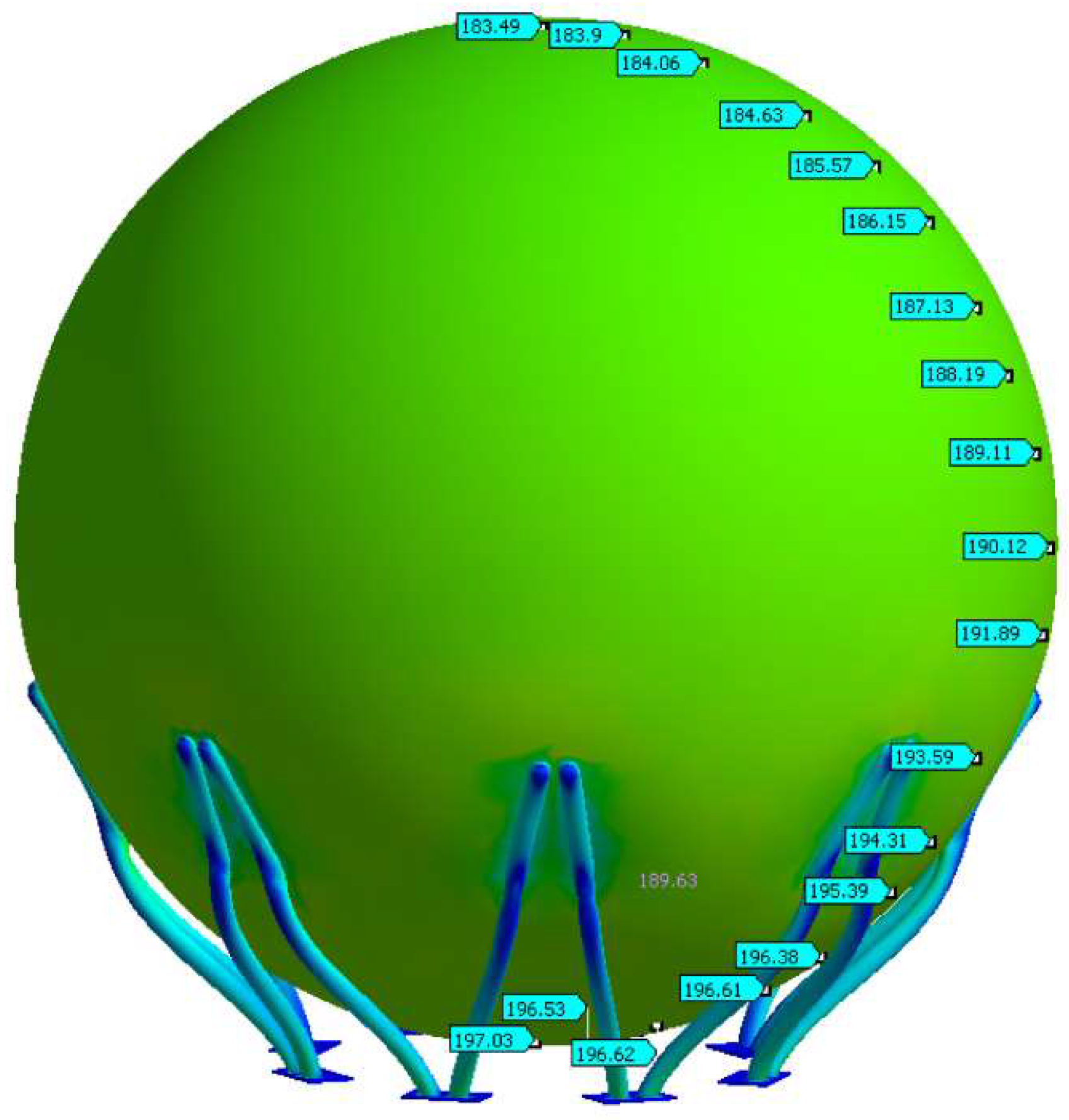
Figure 2.
a) Position of the shell in the form of surface of revolution element, b) Internal forces in the element of the shell in the form of surface of revolution.
Figure 2.
a) Position of the shell in the form of surface of revolution element, b) Internal forces in the element of the shell in the form of surface of revolution.
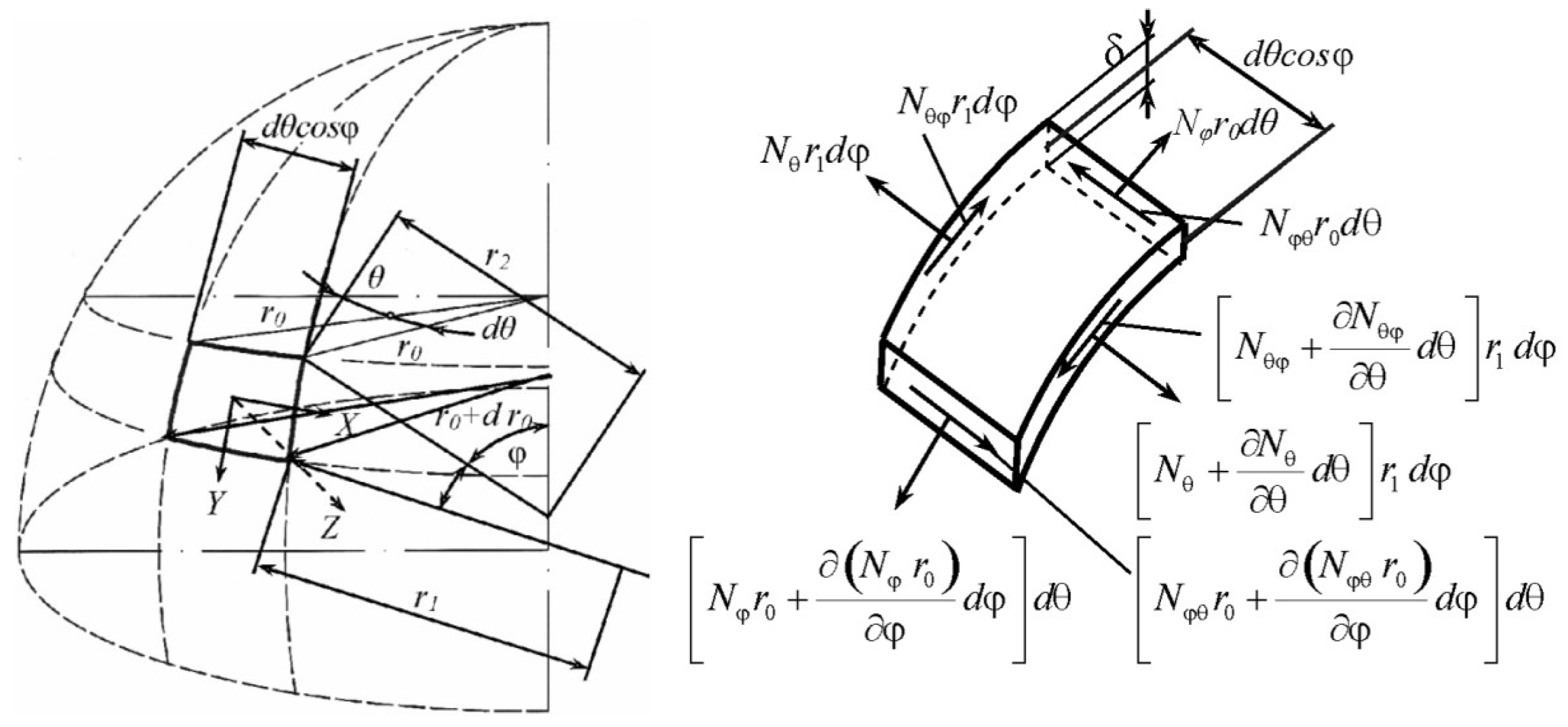
Figure 5.
Equivalent stress values of a spherical tank obtained by applying formulas (7-13).
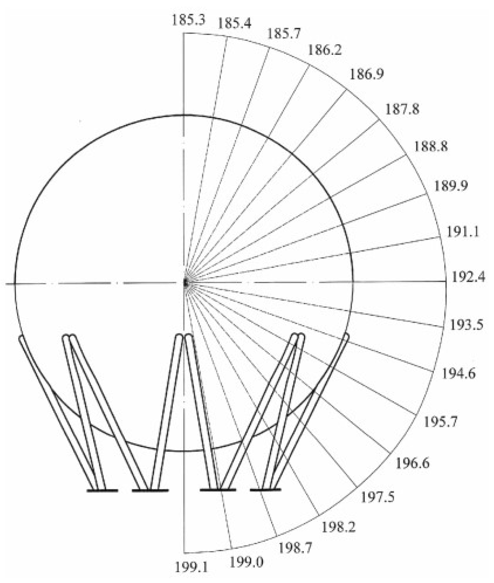
Figure 6.
Equivalent stress distribution of a spherical tank at the support points.
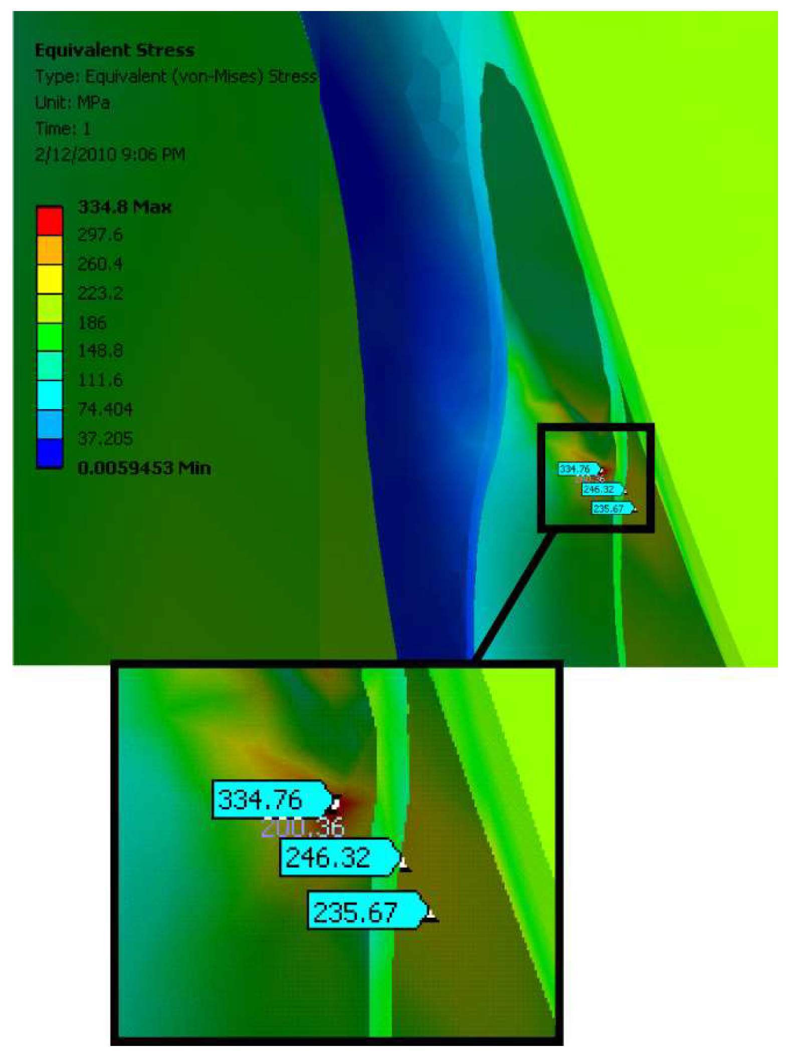
Figure 7.
Deformations of the spherical tank.
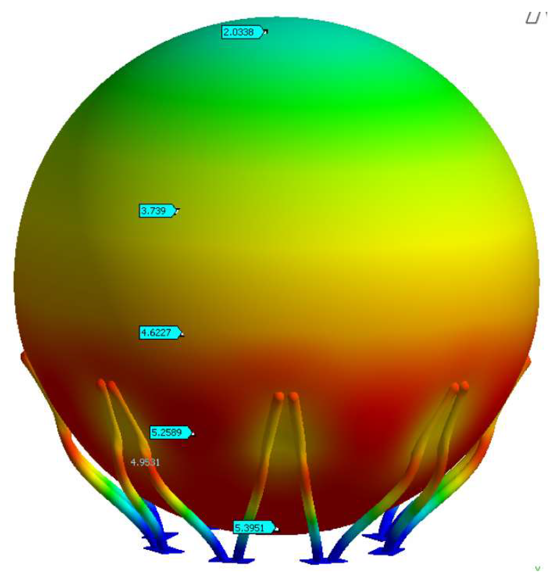
Figure 8.
Arrangement of measuring points.
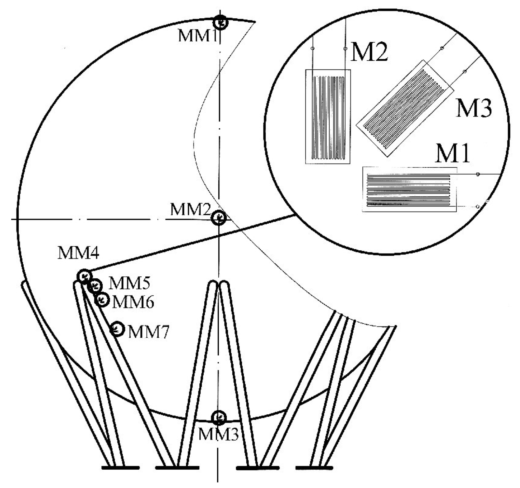
Figure 9.
Strain gauges placed on measuring points MM4÷MM7.

Table 1.
Stresses due to internal pressure and self-weight.
|
Angle φ (º) |
σφ (N/mm2) |
σθ (N/mm2) |
σe (N/mm2) |
| 0 | 185.3 | 185.3 | 185.3 |
| 10 | 185.4 | 185.5 | 185.4 |
| 20 | 185.5 | 185.9 | 185.7 |
| 30 | 185.8 | 186.7 | 186.2 |
| 40 | 186.1 | 187.8 | 186.9 |
| 50 | 186.5 | 189.1 | 187.8 |
| 60 | 186.8 | 190.7 | 188.8 |
| 70 | 187.2 | 192.5 | 189.9 |
| 80 | 187.5 | 194.5 | 191.1 |
| 90 | 187.6 | 196.8 | 192.4 |
| 100 | 196.9 | 189.9 | 193.5 |
| 110 | 197.2 | 191.9 | 194.6 |
| 120 | 197.6 | 193.7 | 195.7 |
| 130 | 198.0 | 195.3 | 196.6 |
| 140 | 198.3 | 196.6 | 197.5 |
| 150 | 198.6 | 197.7 | 198.2 |
| 160 | 198.9 | 198.5 | 198.7 |
| 170 | 199.0 | 198.9 | 199.0 |
| 180 | 199.1 | 199.1 | 199.1 |
Table 2.
Comparative stress values obtained analytically, by FEM model and experimentally.
| Measuring site |
σe (N/mm2)Analytical |
σe (N/mm2) FEM |
σe (N/mm2) Experiment |
| MM1 | 185.3 | 183.5 | 169.6 |
| MM2 | 192.4 | 190.1 | 175.6 |
| MM3 | 199.1 | 197.0 | 182.3 |
| MM4 | - | 334.8 | 343.1 |
| MM5 | 194.6 | 199.5 | 201.0 |
| MM6 | 195.7 | 194.3 | 180.1 |
| MM7 | 196.6 | 195.4 | 182.3 |
Table 3.
Percentage deviation of equivalent voltages.
| Measuring site |
Deviation of results obtained analytically (%) |
Deviation of results obtained by FEM (%) |
| MM1 | 9.3 | 8.2 |
| MM2 | 9.6 | 8.3 |
| MM3 | 9.2 | 8.1 |
| MM4 | - | 2.4 |
| MM5 | 3.2 | 0.7 |
| MM6 | 8.7 | 7.9 |
| MM7 | 7.8 | 7.2 |
Table 4.
Stress values for test pressure.
| Measuring site |
σe (N/mm2) Analytical |
σe (N/mm2) FEM |
σe (N/mm2) Experiment |
| MM1 | 277.4 | 274.1 | 256.9 |
| MM2 | 284.4 | 250.3 | 262.9 |
| MM3 | 291.2 | 288.5 | 272.9 |
| MM4 | - | 444.1 | 483.4 |
| MM5 | 287.8 | 265.5 | 282.3 |
| MM6 | 289.6 | 257.9 | 257.3 |
| MM7 | 290.8 | 259.6 | 261.6 |
Table 5.
Deviation of equivalent stresses obtained analytically and by the FEM model in relation to the results obtained experimentally for the test pressure.
Table 5.
Deviation of equivalent stresses obtained analytically and by the FEM model in relation to the results obtained experimentally for the test pressure.
| Measuring site |
Deviation of results obtained analytically (%) |
Deviation of results obtained by using FEM (%) |
| MM1 | 8.0 | 6.7 |
| MM2 | 8.2 | 4.8 |
| MM3 | 6.7 | 5.7 |
| MM4 | - | 8.1 |
| MM5 | 1.9 | 6.0 |
| MM6 | 12.6 | 0.2 |
| MM7 | 11.2 | 0.8 |
Disclaimer/Publisher’s Note: The statements, opinions and data contained in all publications are solely those of the individual author(s) and contributor(s) and not of MDPI and/or the editor(s). MDPI and/or the editor(s) disclaim responsibility for any injury to people or property resulting from any ideas, methods, instructions or products referred to in the content. |
© 2025 by the authors. Licensee MDPI, Basel, Switzerland. This article is an open access article distributed under the terms and conditions of the Creative Commons Attribution (CC BY) license (http://creativecommons.org/licenses/by/4.0/).
Copyright: This open access article is published under a Creative Commons CC BY 4.0 license, which permit the free download, distribution, and reuse, provided that the author and preprint are cited in any reuse.


