
Submitted:
29 April 2025
Posted:
30 April 2025
You are already at the latest version
Abstract
Aerial craft against the sky are visible in the ultraviolet (UV) range as dark objects. The properties of negative UV contrast differ from the properties of positive thermal contrast. The use of a UV channel in observation devices increases their detection and selection ca-pabilities. The paper analyses the influence of individual components of UV radiation on the signature of an airborne objects and presents the results of calculations of UV radiance and negative contrast depending on the object-observer distance for selected geographical locations and times of day and year as well as on the range of visibility. It was found that UV radiance mostly depends on the sun's elevation, while the contrast depends almost only on the range of visibility, i.e., aerosol’s type and density. A case of negative contrast in atmosphere was measured and the measured data are compared with calculations.
Keywords:
UV negative contrast
; UV background
; UV path radiation
Highlights
UV negative contrast of aircraft in the spectral range 300-400nm depends mostly on aerosols’ scattering just as the extinction of UV radiation during propagation through atmosphere. Therefore the values of negative contrast are close to the values of UV transmittance of the atmosphere and the detection ranges of airborne targets for UV observation devices are close to the visibility ranges.
1. Introduction
The primary source of natural ultraviolet radiation that propagates in the atmosphere is solar radiation which has a temperature of about 5800K. This is the largest UV emitter in nature. Other objects in the atmosphere and on Earth produce small and insignificant radiation. Some artificial sources of interest include emissions from rocket engines, forest fires, etc. [1,2]. Due to the absorption and scattering of oxygen, ozone, and aerosols present in the atmospheric composition [3], only UV-A and UV-B radiation reaches the earth’s surface, UV-C radiation is almost totally absorbed [4]. Emission of radiation in the UV spectrum needs so high temperatures that even aircraft engines and its plumes emit negligible UV radiation [5,6]. The above results in the aircrcraft’s black silhouettes on a UV solar background (negative contrast). The negative contrast appears because the target blocks the part of UV path radiation [7].
The paper focuses on calculating the target’s negative UV contrast by taking into consideration such factors as a target silhouette, background, and solar path radiation. The UV radiance was calculated using PCModwin software (a version of the Moderate Resolution Atmospheric Transmission – (MODTRAN) on the Windows platform). MODTRAN resolution is sufficient as the radiation in wide UV spectral regions is calculated and integrated. First background and object-observer path radiance has been calculated for the selected targets, next the contrast has been found and finally signal-to-noise ratio (SNR) for the selected target and UV camera has been determined.
2. Modeling the Negative Contrast
Optical signatures are referred to as the radiometric characteristics of an object. The optical signature of an object is characterized by the self-emitted radiant flux, the transmitted flux, and the flux reflected from the object’s surface [8]. The optical signatures of the target depend on many factors specific for the objects (targets) and the atmosphere. The main factors are:
- Object properties: Size, shape, surface temperature, texture, emissivity, reflectivity,
- Environmental conditions: solar zenith angle, geographical location, time of a day and season of the year, density and specification of aerosols, etc.
C.J. Willers et al. have provided a scene simulation model for optoelectronic devices covering the 0.2-20 μm spectral region [9,10,11]. The radiation components taken into account in the above model include (Figure 1):
- Direct sunlight, cloud scattered sunlight, thermal and scattered skylight,
- Ambient reflection and thermal radiation.
- Atmospheric thermal self-exitance, atmospheric scattered sunlight (molecular and aerosol scattering).
- Thermal radiation of the target, radiation reflected by the target (sunlight, skylight, and ambient light).
In the short wavelength range (300nm-400nm) diffusely reflected skylight, reflected sunlight, ambient, and thermal radiation are negligible so they can be ignored [6]. Only the atmospheric path radiance becomes important and is calculated. The substantial difference in the UV region between path radiance and target thermal radiance is presented in Figure 2.
The horizontal visibility is limited by the composition of the atmosphere, and the specification of aerosol particles, clouds, and water vapor. We assume that a target not emitting UV radiation is located against the background (EB) at a distance R from the observer searching for objects through the background (Figure 3) [12].
Weber contrast C between target and background is defined as:
The negative contrast is equal to ( :
where EB - the background radiance,
ET - the path radiance between a target and a sensor.
If a target perfectly absorbs UV radiation and is too cold to emit UV radiation, it is no reflection and emission from it. At a short distance, the target is seen as black by the observer. As the distance between the target and the observer grows, the UV radiation is scattered into the observer’s field of view, decreasing the contrast between the target and the background. The further away, the more intense this scattered light is, and at a certain distance from the object the observer can barely distinguish between the target and the background.
3. Results and Discussion
In the study, PcModWin software (Modtran code) is used to compare various seasonal and atmospheric conditions and locations [13]. The selected locations for calculation are Warsaw (Poland) with latitude and longitude coordinates 52.2 and 21 respectively, and Hanoi (Vietnam) with latitude 21 and longitude 105.8.
Due to the difference in geographical locations, atmospheric models must be selected accordingly. In PcModWin the Mid-latitude Summer and MID-Latitude Winter atmospheric models are used to calculate the radiation in Warsaw area and respectively Tropical model is used for Hanoi area.
In UV and VIS regions scattering caused by aerosols is a main reason for reduced visibility. Therefore, in the survey, we conducted simulations for four various aerosol models: rural with 23km visibility, rural with 5km visibility, urban with 5km visibility, urban with 2 km visibility. Radiance is calculated at noon on summer and winter solstice. The observer looks along a slant-path with zenith angle 850 (near horizon, elevation 50). The 300nm-400nm radiance function versus observer-object distance is calculated for two selected locations and the selected aerosols (rural and urban) and visibilities. The results are presented in Figure 4.
The results presented in Figure 4 show that the radiation at the observer’s location increases with the distance to the target. The total value of UV radiation computed for Hanoi is higher than in Warsaw due to its proximity to the equator and the higher position of the Sun. The results of calculations show also that the level of path UV radiation is defined by two main factors, which are the elevation of the Sun (Figure 5) and visibility (aerosol density and size of the particles).
Next, Weber’s contrast between the target and the background has been calculated according to formula (2). The results are shown in Figure 6.
It is noticeable that the contrast curves are almost the same and overlap for Hanoi and Warsaw (Figure 6) despite much higher UV radiation in Hanoi than in Warsaw (Figure 4). It proves that the UV contrast depends almost only on meteorological visibility defined by aerosol and molecular scattering. Even a type of aerosol has little influence on UV negative contrast, that is noticeable if one compares the contrast curves for atmospheres with rural and urban aerosols of the same 5km visibility.
The calculations were compared with some measurements of negative contrast given by a few buildings in Warsaw located at various distances. The contrast was measured with a Si Avalanche Photodiode with a UV filter as it is shown in the below photo (Figure 7). Measurements were performed on a partly cloudy summer day at 10 a.m. Relatively good agreement was found between measurements and calculations for summer atmosphere with urban aerosol and for 3km visibility (Figure 8).
It can be noticed that the shape of the contrast and transmittance curves are similar (Figure 6 and Figure 9) for the same aerosol model as both contrast and transmittance depend mainly on aerosol scattering. Transmittance is decreasing with propagation distance as the source radiation is scattered out of the observer’s field of view, while contrast is also decreasing with distance between object and observer as radiation propagating in atmosphere is scattered into observer’s field of view.
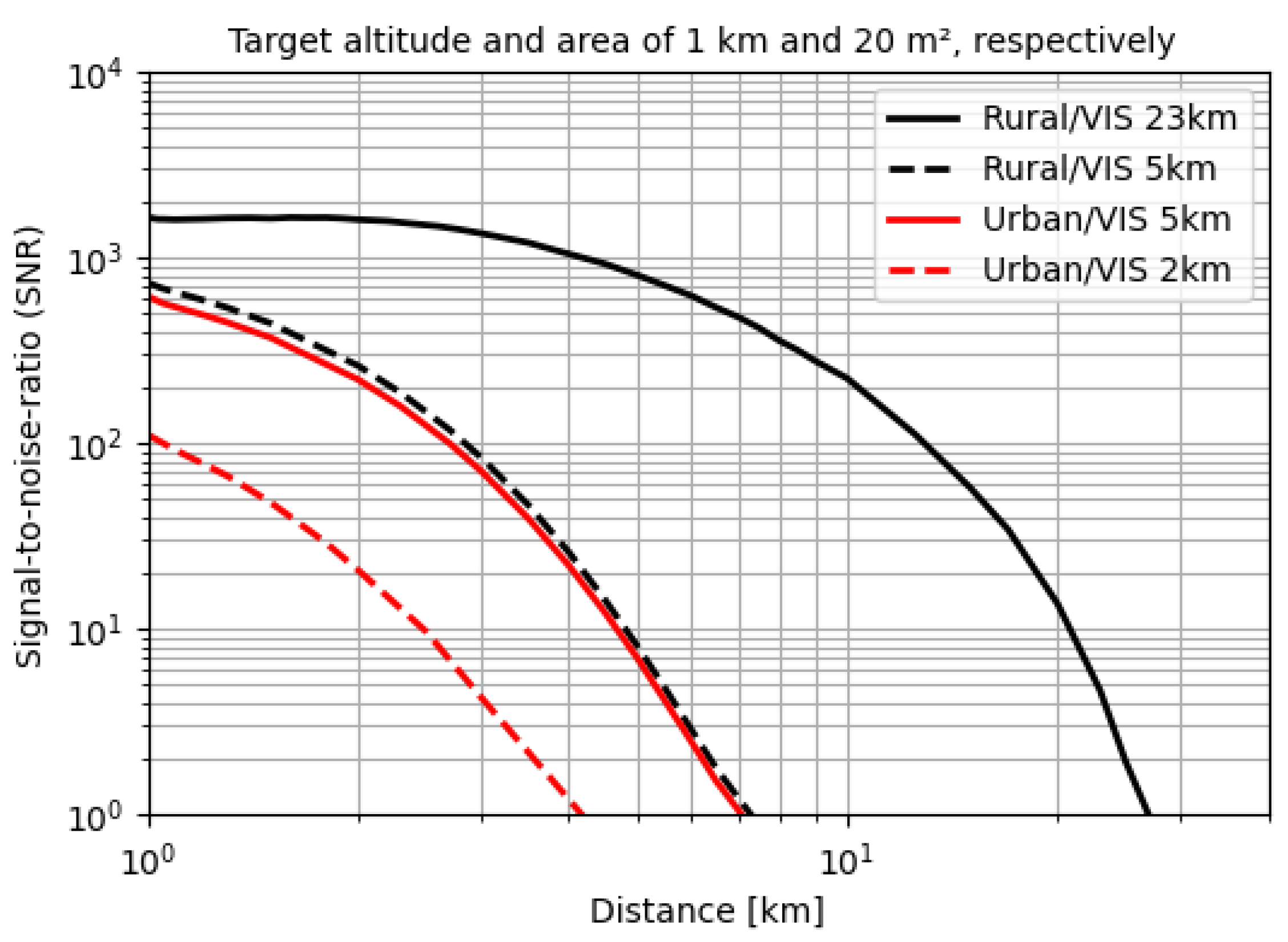
Target detection range can be determined based on signal-to-noise ratio (SNR). In general, the limit of performance of a photon detector depends on the photon noise, which appears as a random voltage or current at the detector’s output terminals. The total noise from the detector is the root mean square (rms) sum of the detector’s intrinsic noise plus the photon noise [14].
Φts and Φb are the radiant flux from a target silhouette area and from background at a pixel, η is the quantum efficiency of the detector, h is the Planck constant, c is the speed of light in vacuum, τ is the integration time of image acquisition, λ is the central wavelength, NEP is the equivalent power of the dark current noise of the pixel. Coefficient γ depending on the ratio of solid angles of a target silhouette (Ωts) and a single pixel (Ωp) is equal to
The signal-to-noise ratio (SNR) was calculated for an observation device (UV camera) with the following parameters: spectral band 320-400 nm, pixel size 15x15µm, quantum efficiency η=0.5, integration time τ equal to 20ms (bandwidth 25Hz), specific detectivity D*=5∙1010 cm·Hz1/2·W-1 (that corresponds to NEP of 1.5∙10-13W). The parameters of the objective lens are focal length 50 mm, aperture 20mm (F/2.5, NA=0.196) and optics’ transmittance Topt = 90%.
The radiant flux Φts and Φb on a single pixel are equal to
where Lb/s is radiance from a target silhouette or background and Sp is a pixel area. The radiances were calculated using PCMODWIN for the noon of spring equinox, cloudless sky, rural aerosols of visibilities 23km and 5km and urban aerosols of visibilities 5km and 2km.
The calculations were performed for a target of 20m2 area and flying at 1km altitude.
It can be noticed that SNRs (and therefore detection ranges) for the defined target depends mostly on visibility and only slightly on the type of aerosol. It results also from the above diagram (Figure 10) that the range of detection for the selected device is close to ranges of atmosphere visibilities as scattering is dominant in both UV and VIS bands.
4. Conclusion
The general model for UV signatures of airborne objects includes many factors: radiation from the target, background, solar path radiation, and others. However, only the solar path radiation plays a major role in the total radiance at the sensor. The remaining components of the UV signature are insignificant.
The airborne target blocks the radiation path behind it that produces a negative contrast. Calculating the negative contrast for various environmental conditions is important for the prediction of detection, recognition and/or identification ranges of optoelectronic devices.
Comparing simulation results under different conditions, it has been found that:
- background radiation depends mainly on the level of insolation i.e., elevation of the Sun, cloudiness, aerosol density and factors impacting visibility, etc.
- contribution of thermal emission to UV signatures of airborne targets is negligible
- negative contrast of airborne targets does not depend on the level of insolation but only on visibility (cloudiness, aerosol density and characteristics, etc.)
- as the level of direct sunlight is much higher than scattered one, sunlight blinks (sunlight reflected by the target) may significantly disturb the process of detection
- detection ranges of airborne targets for the selected UV observation device are close to visibility ranges (Figure 10).
Author Contributions
Conceptualization: K.Kopczyński and M.Zygmunt, Metodology: Z.Zawadzki, Software: D.N.Hiep and Z.Zawadzki, Computation and Analysis: D.N.Hiep and Z.Zawadzki, Measurements of UV Radiance: D.Wróblewski, Writing – Original Draft: D.N.Hiep and Z.Zawadzki, Writing – Review: K.Kopczyński and M.Zygmunt, Project Administration and Supervision: K.Kopczyński
Funding
This research received no external funding.
Conflict of interests
The authors declare no conflict of interest.
References
- Zheng D, Huang D-G, De-Yin Z. Investigation of Ultraviolet Transmission Characteristics of Detecting Window in Ultraviolet Fire Detector. Journal of Electronic Science and Technology of China. 2006 Jun; 4(2): 144-147.
- Huang H, Jia H, Yin H, Chang S, and Yang J. Analysis of transmission and application of UV radiance of missile plume. 6th International Symposium on Advanced Optical Manufacturing and Testing Technologies: Optical Test and Measurement Technology and Equipment, SPIE. 2012 Oct 15; 8417, 84172U. [CrossRef]
- Forster P. M. D. F. Modeling ultraviolet radiation at the Earth’s surface. Part I: The sensitivity of ultraviolet irradiances to atmospheric changes. Journal of Applied Meteorology and Climatology. 1995 May; 34(11):2412-2425. https://journals.ametsoc.org/view/journals/apme/34/11/1520-0450_1995_034_2412_murate_2_0_co_2.xml.
- Diffey B. L. Sources and measurement of ultraviolet radiation. Methods. 2002 Jun; 28(1):4-13. [CrossRef]
- Kumar D, Smith L, Richardson M, Ayling R, Barlow N. Modelling a man-portable air-defence (MANPAD) system with a rosette scan two-color infrared (IR) and ultraviolet (UV) seeker. Technologies for Optical Countermeasures XI; and High-Power Lasers 2014: Technology and Systems, SPIE. 2014 Oct; Vol. 9251: 137-150). [CrossRef]
- Smith L, Richardson M, Walmsley R. Comparison of MODTRAN5 to measured data in the UV band. Technologies for Optical Countermeasures X; and High-Power Lasers 2013: Technology and Systems, SPIE. 2013 Oct; Vol. 8898, 88980F. [CrossRef]
- James L. Physics-based performance model of a UV missile seeker. Technologies for Optical Countermeasures XIV, SPIE. 2017 Oct; Vol. 10435: 86-102. [CrossRef]
- Birchenall R, Richardson M, Butters B, Walmsley R. Modelling the infrared ManPAD track angle bias missile countermeasure. Infrared Physics & Technology. 2011 Sep; 54(5): 12-421. [CrossRef]
- Willers CJ. Electro-optical system analysis and design: a radiometry perspective. Society of Photo-Optical Instrumentation Engineers, 2013. [CrossRef]
- Willers MS and Van Den Bergh JSH. Optronics sensor development using an imaging simulation system. 2011 Saudi International Electronics, Communications and Photonics Conference (SIECPC). 2011. [CrossRef]
- Willers CJ, Willers MS, Fabian Lapierre. Signature modelling and radiometric rendering equations in infrared scene simulation systems. Technologies for Optical Countermeasures VIII. SPIE. 2011 Oct; Vol 8187: 173-188. [CrossRef]
- James I. Modelling ultraviolet threats. Technologies for Optical Countermeasures XIII, SPIE. 2016 Oct; Vol 9989(998909): 23-31. [CrossRef]
- Berk A et al. MODTRAN ® 6.0.0 User’s Manual (revision 5). Spectral Sciences. Inc., Burlington. SSI-TR-685, 2016.
- Rogalski, A.; Bielecki, Z.; Mikołajczyk, J.; Wojtas, J. Ultraviolet Photodetectors: From Photocathodes to Low-Dimensional Solids. Sensors 2023, 23, 4452. https://www.mdpi.com/1424-8220/23/9/4452.
Figure 1.
Radiation components in the scene.
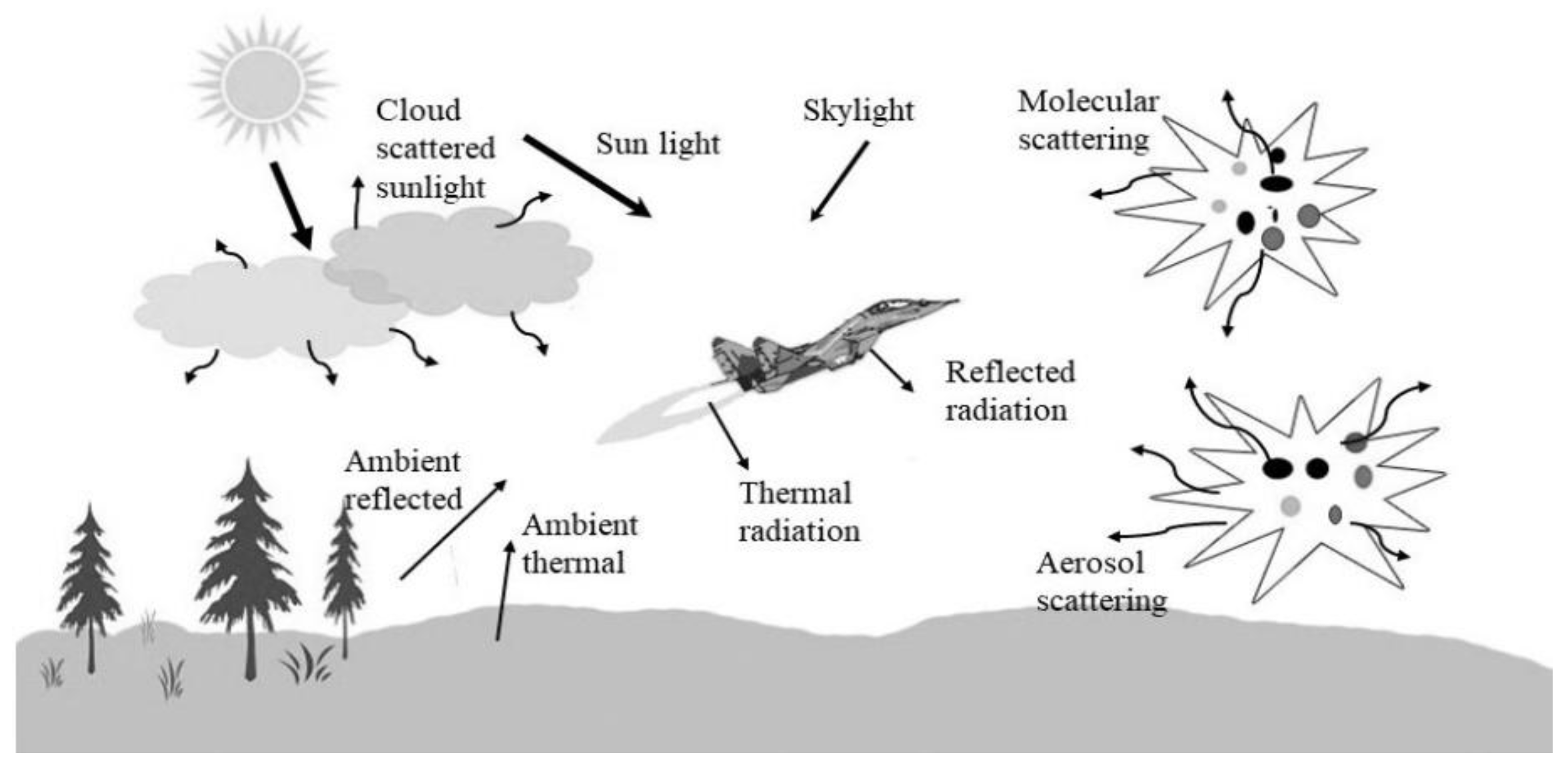
Figure 2.
Thermal radiation of the target and path radiation (300-400nm)
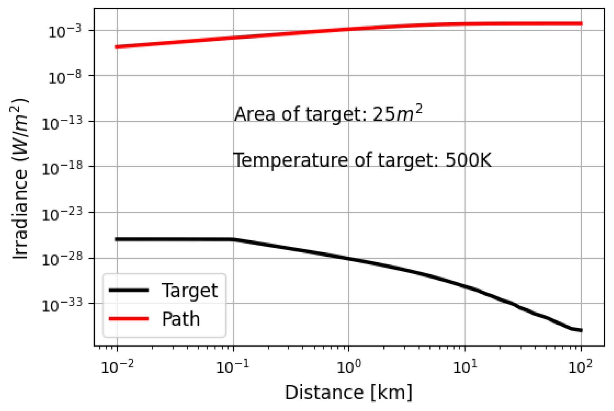
Figure 3.
The visibility of the target depends on the distance between the target and the observer. (a) R=0.5km, Cneg=0.8; (b) R=1.5km, Cneg=0.6; (c) R=4.5km, Cneg=0.22.
Figure 3.
The visibility of the target depends on the distance between the target and the observer. (a) R=0.5km, Cneg=0.8; (b) R=1.5km, Cneg=0.6; (c) R=4.5km, Cneg=0.22.
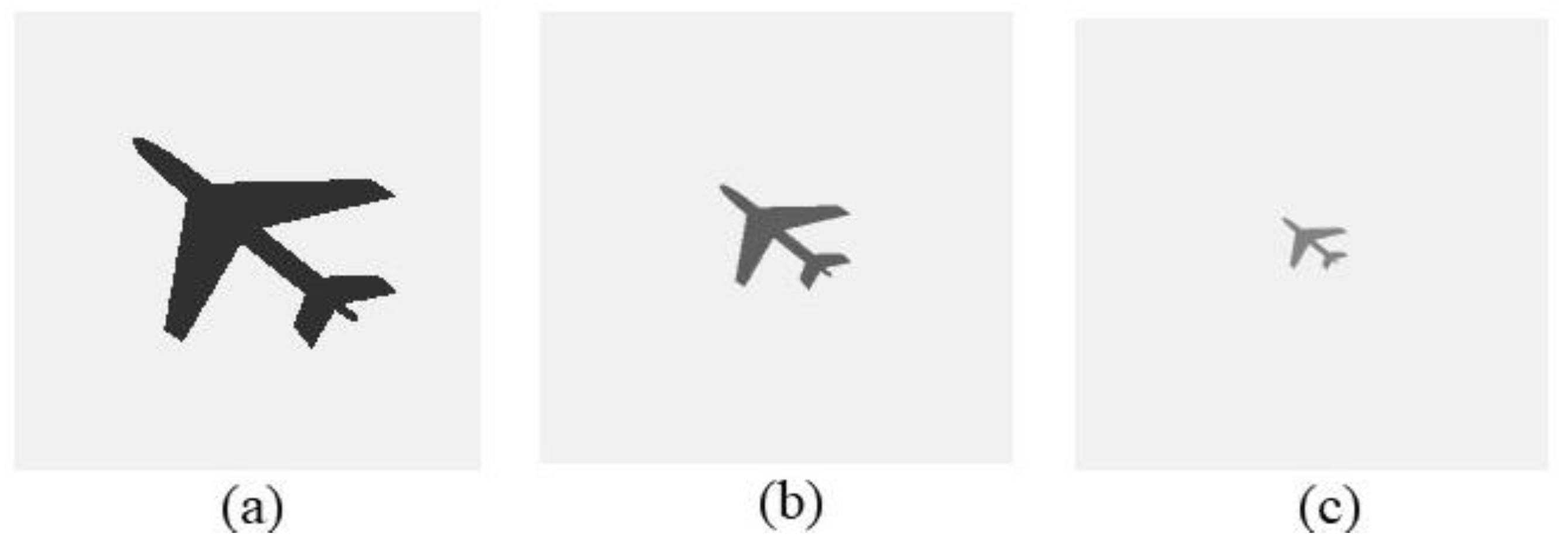
Figure 4.
Path UV (300÷400nm) radiance in Warsaw and Hanoi (ground situated observer), rural aerosol with 23km and 5km visibility on summer (a) and winter (b) solstice, urban aerosol with 5km and 2km visibility on summer (c) and winter (d) solstice.
Figure 4.
Path UV (300÷400nm) radiance in Warsaw and Hanoi (ground situated observer), rural aerosol with 23km and 5km visibility on summer (a) and winter (b) solstice, urban aerosol with 5km and 2km visibility on summer (c) and winter (d) solstice.
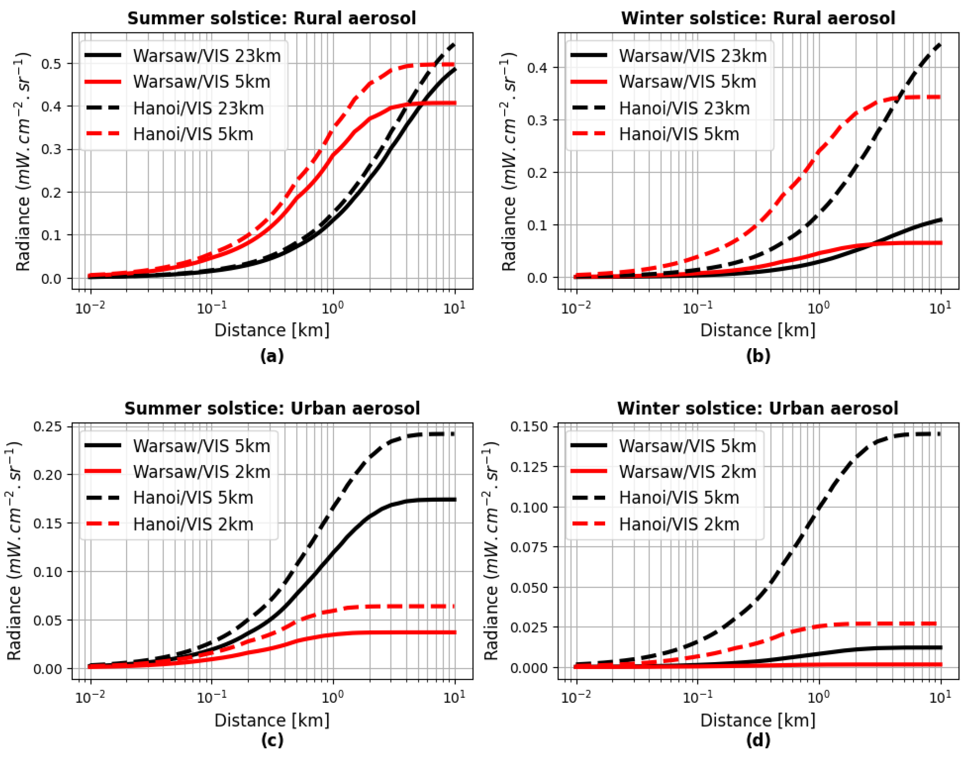
Figure 5.
Radiance dependence on the daytime (61.2o maximum solar elevation angle).
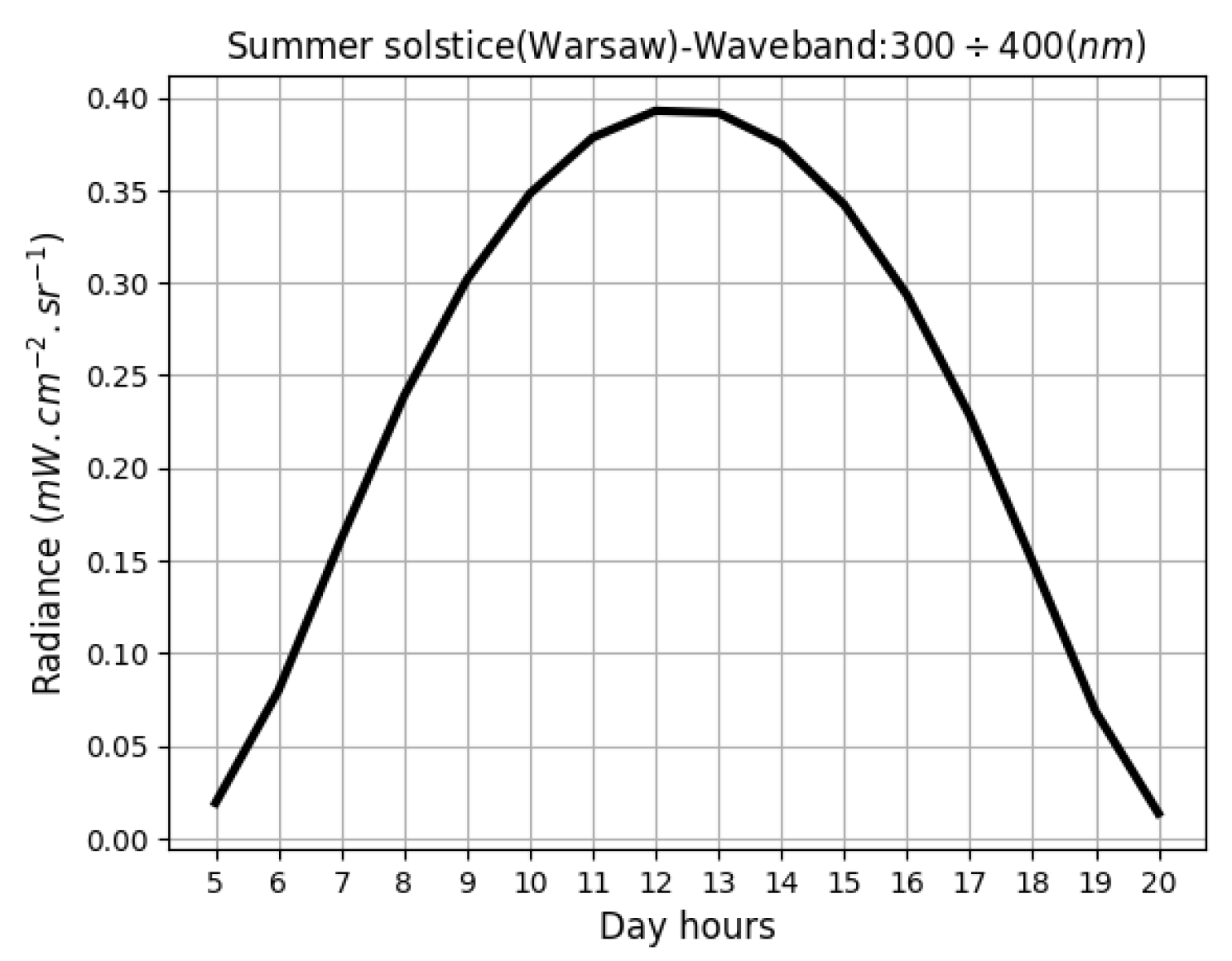
Figure 6.
Figure 6. Negative contrast versus range, rural aerosol with 23km and 5km visibility on summer (a) and winter (b) solstice, urban aerosol with 5km and 2km visibility on summer (c) and winter (d) solstice.
Figure 6.
Figure 6. Negative contrast versus range, rural aerosol with 23km and 5km visibility on summer (a) and winter (b) solstice, urban aerosol with 5km and 2km visibility on summer (c) and winter (d) solstice.
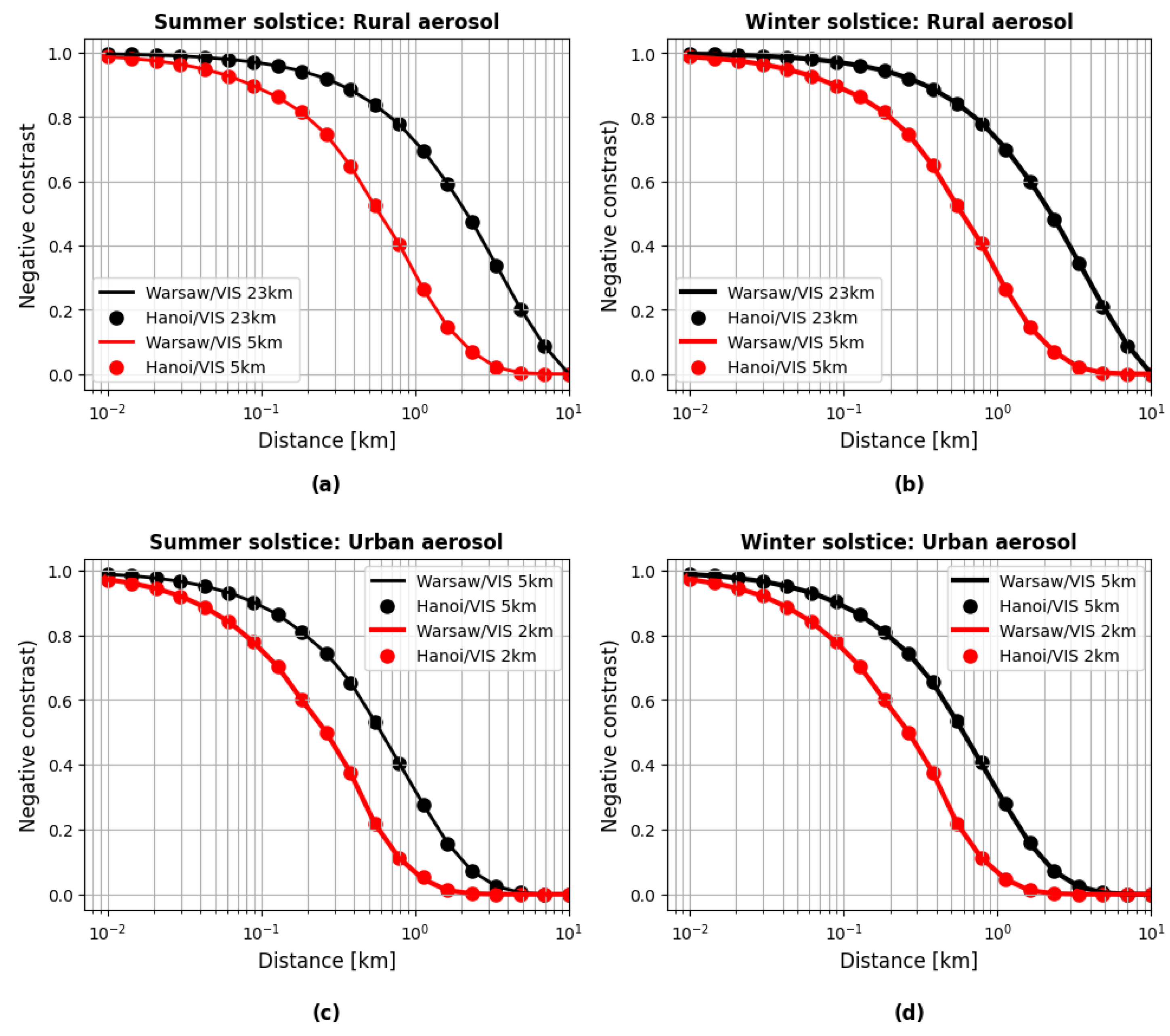
Figure 7.
Measuring device: Si Avalanche Photodiode with a UV filter (upper) with visible sight camera (lower).
Figure 7.
Measuring device: Si Avalanche Photodiode with a UV filter (upper) with visible sight camera (lower).
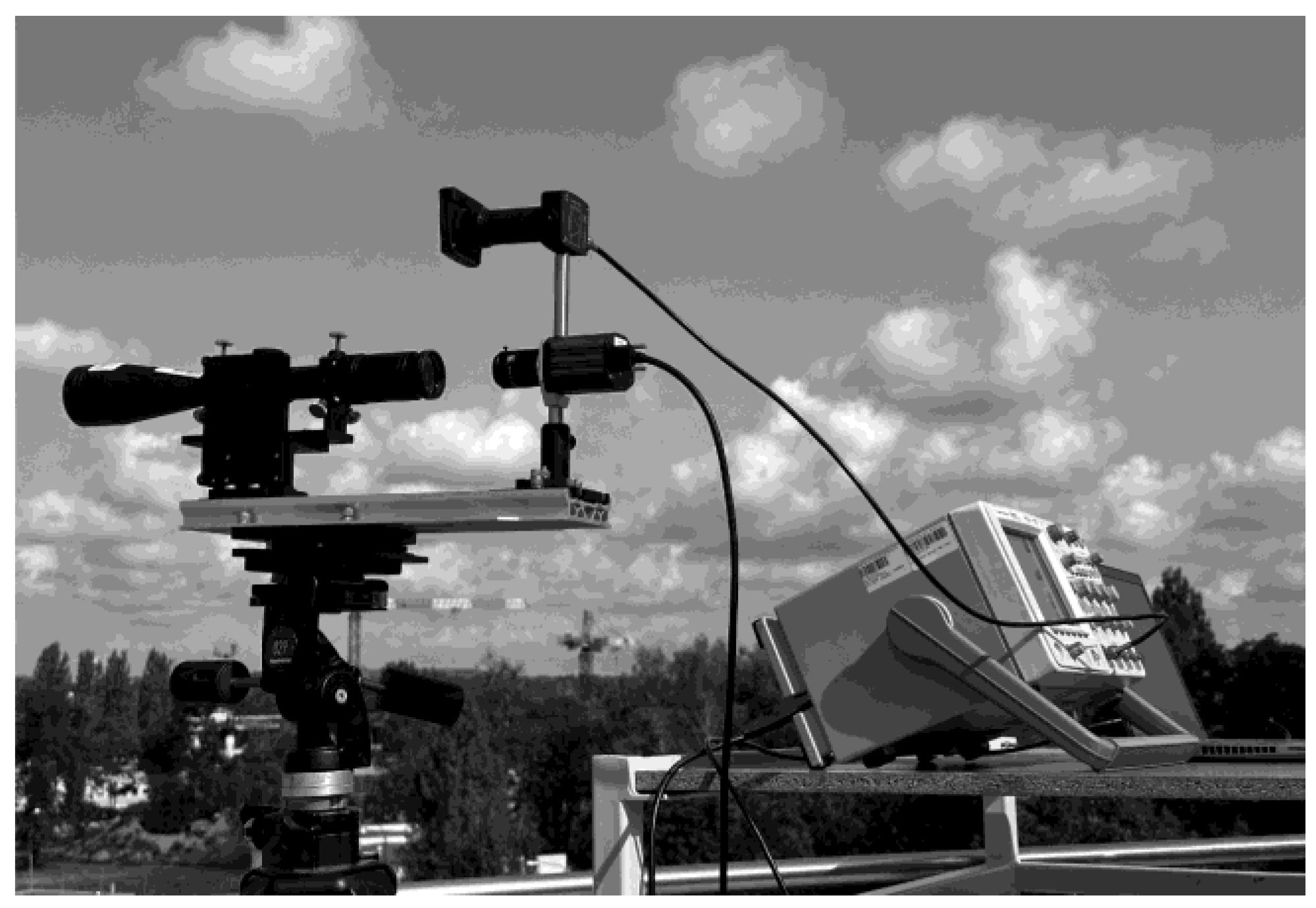
Figure 8.
The measured (red points) and calculated (black curve) negative contrast.
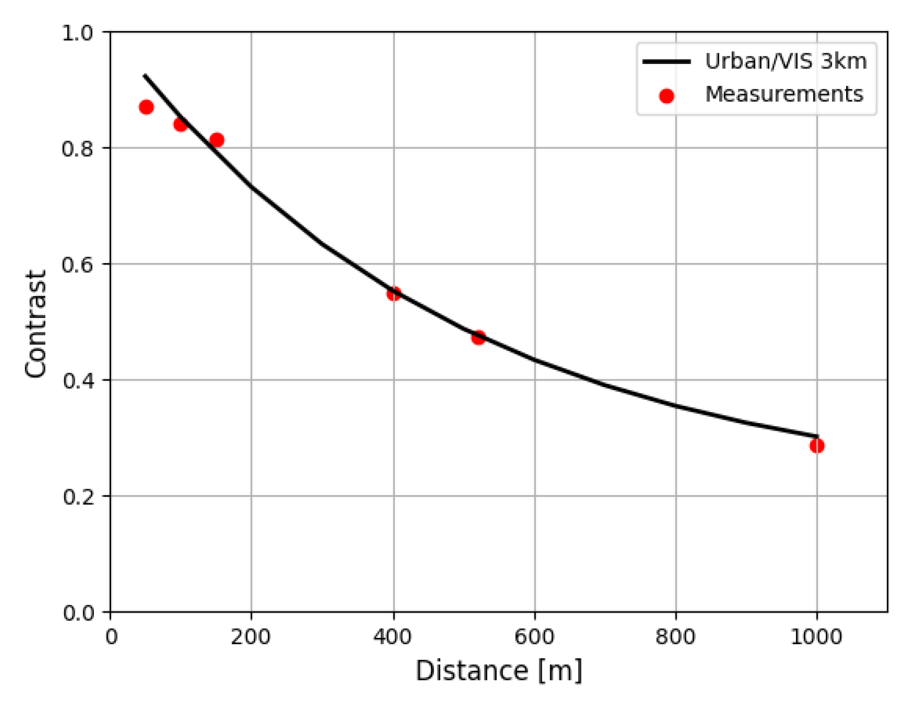
Figure 9.
Transmittance in the atmosphere.
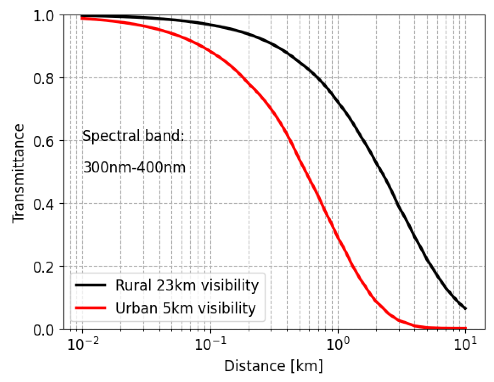
Figure 10.
SNR as a function of distance of various visibilities.
Disclaimer/Publisher’s Note: The statements, opinions and data contained in all publications are solely those of the individual author(s) and contributor(s) and not of MDPI and/or the editor(s). MDPI and/or the editor(s) disclaim responsibility for any injury to people or property resulting from any ideas, methods, instructions or products referred to in the content. |
© 2025 by the authors. Licensee MDPI, Basel, Switzerland. This article is an open access article distributed under the terms and conditions of the Creative Commons Attribution (CC BY) license (http://creativecommons.org/licenses/by/4.0/).
Copyright: This open access article is published under a Creative Commons CC BY 4.0 license, which permit the free download, distribution, and reuse, provided that the author and preprint are cited in any reuse.


