
Submitted:
28 April 2025
Posted:
29 April 2025
You are already at the latest version
Abstract
Integration of ground-penetrating radar (GPR) with unmanned aerial vehicles (UAVs) promises new possibilities for non-invasive archaeological site identification, especially where areas are hard to reach or sensitive to disturbance. This research investigates utilization of GPR technology mounted on a UAV to identify a World War II hiding place of significance, the 'Onderduikhol,' next to Bornerbroekseweg, Wierden municipality, the Netherlands. During aerial surveys, a Compact Broadband Detector (CBD) GPR system was placed on a DJI Matrice 600 Pro UAV, supplemented by ground measurements with GPR for validation. No conclusive indications of the hiding structure were observed, but a number of shallow planar reflection anomalies were recognized, indicative of possible areas of historical subsurface disturbance. This work proves the promise of rapid archaeological prospection using UAV-GPR while identifying main issues, such as soil water effects, flight stability, as well as interpretation uncertainties. By integrating drone-based with conventional survey techniques, this research provides rich insight into the advantages, constraints, and opportunities of UAV-GPR for cultural heritage management.
Keywords:
Ground-Penetrating Radar (GPR)
; UAV Drone-Based sensors
; Remote Sensing
; Cultural Heritage Preservation
; Anomaly Detection
; Radargram
; Non-Invasive Prospection
1. Introduction
Non-invasive geophysics techniques have transformed the conduct of archaeological investigations by making it possible to detect and characterize subsurface features without tampering with sensitive or protected areas. Ground-penetrating radar (GPR) is a versatile and widely used method of archaeological prospection within these techniques. GPR operates by transmitting electromagnetic waves into the ground and records reflections from subsurface structures with contrasting dielectric properties. This makes GPR a valuable method for the determination of buried walls (archeological structures, unknown objects and graves, foundations, voids, and stratigraphic discontinuities [1,2]
Traditionally, GPR surveys were performed manually with handheld or cart-mounted units, with researchers having to walk across systematically over survey areas. While effective, there are several drawbacks with such a method: physical access to the site, time constraints for larger survey areas, and possible interference with delicate surfaces [3]. Additionally, on densely vegetated, marshy, or otherwise hazardous ground, ground-based GPR surveys can prove not feasible at all.
The combination of GPR technology with unmanned aerial vehicles (UAVs) provides a viable alternative to existing practices. UAV-mounted GPR technology can cover extensive areas using a minimally ground-disturbing approach with high speed, yielding new chances for the detection of archaeologically significant features within demanding topography [4,5,6]. New problems are, however, introduced with the technology, including the need for a stable flight altitude to produce high-quality data, signal loss through variations in the soil, as well as a reduction compared to ground-based technology in achievable spatial resolution [7,8,9]
Despite these challenges, UAV-based GPR is proving to be a valuable tool for remote sensing archaeology, especially for reconnaissance surveys, risk assessments, and the identification of areas for more extensive excavation. Nonetheless, there are few documented uses of UAV-GPR systems for real archaeological case studies, and more work is necessary to test their performance under a wide range of field conditions [10]
The subject of the current research is the application of UAV-based GPR for detecting archaeological sites by means of a case history of finding a WWII hiding place, the “Onderduikhol,” situated near Bornerbroekseweg, Wierden municipality, the Netherlands. Several Jewish families hid during World War II under the German occupation inside such improvised shelters as the Onderduikhol. Many of these locations were hidden purposely, and their exact positions have now been lost to history.
Based on historical records and testimonies, the suspected hiding place was believed to be located in agricultural fields bordered by Bornerbroekseweg, Huttemansweg, and Entelerweg. The structure, a buried chicken coop modified for camouflage, was estimated to have a size of around 4 × 7 meters with a depth of around 60 centimeters.
To identify possible remnants of the Onderduikhol, a comprehensive geophysical survey was conducted with a drone- mounted Compact Broadband Detector (CBD) [11] GPR system combined with a DJI Matrice 600 Pro [12] Unmanned Aerial Vehicle (UAV), supplemented by a handheld ground-based survey for validation. This article outlines the methodology, results, and reflections from the survey, as well as considers the wider implications of the application of UAV-based GPR for archaeological and heritage contexts.
By bringing actual field data and insights to bear, the research strives to improve the knowledge of UAV-GPR applications within archaeological prospection as well as identify its strengths and weaknesses when applied to sensitive historic investigations.
Scientific Contribution
Scientifically, the research contributes to the validation of GPR conducted with a UAV for heritage archaeology, with a strong focus on identifying small-scale historic structures under complex soils. It presents a critical examination of the performance and interpretation constraints of operating a UAV-GPR system within real-life heritage applications.
Practical Contribution
Practically, the research supports cultural heritage preservation efforts by proposing efficient, non-invasive methods that can help historians, archaeologists, as well as municipalities, identify hidden or lost history sites without actual excavation.
In this paper, Section 2 outlines materials, equipment, and data acquisition protocols employed while conducting the UAV and ground-based surveys. Section 3 provides results, including the most pronounced subsurface anomalies that were found. Section 4 addresses interpretation of results encountered limitations, as well as wider implications for applications of UAV-GPR to archaeology and other fields, like crime investigation [13,14,15]. Finally, Section 5 concludes with a summary of insights gained and recommendations for future research and heritage investigations.
2. Materials and Methods
2.1. Overview of Ground-Penetrating Radar Technology
Ground-penetrating radar (GPR) is a geophysical method that relies on the propagation of electromagnetic waves to image and detect subsurface features. GPR works by emitting short bursts of high-frequency radio waves into the ground and measuring the reflections from subsurface structures due to contrasted dielectric properties [16]. Radargrams resulting therefrom exhibit layering, voids, buried structures, and other anomalies, which renders GPR a proven method of archaeological prospection [17]
The penetration depth and the level of detail of GPR data are governed by a number of controlling factors such as the frequency of the antenna, composition of the ground, groundwater content, and the electrophysical characteristics of the surveyed material [1] Low-frequency antennae (e.g., 100–400 MHz) can provide deep penetration but lose detail, while high-frequency antennae (e.g., 500–1000 MHz) can offer more detail but less penetration. A trade-off between penetration depth and detail is desirable for archaeological applications, particularly where buried small-scale structures are at reasonably shallow levels.
Application of GPR-based platforms using UAVs was recently designed to address constraints inherent with conventional surveys, including restricted access to sensitive zones, fatigue of surveyors, and the need to cover extensive ground areas [18]. Installation of GPR equipment on a UAV provides for fast, regular, and non-intrusive surveying, while issues of maintaining a constant flight height and signal weakening due to conductivity of the ground need to be overcome for effective application [19]
2.2. Equipment and Data Collection
2.2.1. UAV Platform
An aerial survey was performed using a DJI Matrice 600 Pro (M600 Pro) [12] unmanned aerial vehicle (UAV), a heavy-lifting, professional hexacopter designed for high-stability flight with heavy payloads. M600 Pro incorporates a six-rotor platform, a GNSS/RTK positioning system for true precision positioning, and the A3 Pro flight controller for repeatable, accurate flight trajectories even under moderate wind speeds. M600 Pro can carry a maximum payload of around 6 kg with a standard flight duration of 16–30 minutes under varying payload and battery configurations.
The UAV was operated at around 2 meters above ground level for this research. This was chosen to maximize the trade-off between signal penetration and resolution. Altitude changes of a small magnitude were present while flying due to ground effects as well as environmental factors, a common problem for GPR applications using drones [20,21]. Future development can involve the inclusion of real-time altitude control devices, for example, laser rangefinders or downward-pointing radar altimeters, to improve data consistency.
2.2.2. GPR Sensor
The GPR device utilized was the Compact Broadband Detector (CBD) GPR produced by Radarteam Sweden AB [11]. This lightweight, UAV-mounted GPR device is optimized for hard-to-reach area geophysical imaging.
Operating within a wide frequency range of around 400 to 800 MHz, the CBD GPR provides a reasonable compromise between penetration depth and resolution for finding archaeological objects within the top 2–3 meters of the subsurface.
- Key specifications of the CBD GPR include:
- Antenna frequency range: 400–800 MHz
- Penetration depth: up to ~3 meters, depending on soil conditions
- Weight: approximately 3–4 kg
- Data acquisition: high-speed radargram collection with GNSS-tagged coordinates
- Software compatibility: Prism2 platform for data processing and visualization
The CBD GPR unit was mounted beneath the UAV using a custom suspension system designed to minimize vibrations and mechanical interference during flight.
2.2.3. Data Collection Protocol
Data collection was conducted during two dedicated field campaigns:
- March 31, 2025 - Initial UAV-based survey covering both left and right sections of the test field.
- April 9, 2025 - Ground-based survey of the right section of the test field using the same GPR sensor mounted on a wheeled cart for comparative analysis.
The survey using the UAV employed predetermined flight lines with overlapping passes to obtain complete coverage of the area of concern. Eight individual flights (Flight 1–8) were conducted with attention to both extensive field coverage as well as specific high-probability areas derived from preliminary results. Each radargram was geotagged with GNSS data to allow spatial correlation with aerial imagery and ground features.
At the same time, a ground-based survey was conducted using the same GPR mounted on a manually operated cart. Three paths (Path 1–3) were surveyed, with a focus on the right half of the field, which was recognized as the most likely place for the Onderduikhol due to records. All the GPR data were captured as binary data and later processed with Prism2 software for visualization, filtering, and interpretation.
2.3. Data Processing and Analysis
Preprocessing and interpretation were performed using Prism2 [22], a specialized software suite designed for GPR data handling. The following standard preprocessing steps were applied:
- Time-Zero Correction - Aligning the start of each radargram to a common reference point to ensure consistent depth scaling.
- Background Removal - Eliminating constant reflections from the surface and background noise to enhance subsurface anomaly visibility.
- Gain Adjustment - Applying signal amplification functions to compensate for attenuation with depth, allowing clearer visualization of deeper layers.
- Migration (where necessary) - Correcting hyperbolic reflections to better localize point targets.
Analysis was targeted towards the identification of planar reflections, hyperbolic signatures, and localized anomalies that are indicative of possible anthropogenic structures. Special attention was directed towards depths within the range of 0.2 meters to 3 meters, consistent with the predicted burial depth of the Onderduikhol and associated features.
3. Results
3.1. Drone-Based Survey Results
Eight UAV-based GPR flights were conducted over the study area, targeting both the left and right sections of the field near Bornerbroekseweg. The primary aim was to detect planar reflections, localized disturbances, and hyperbolic features that could indicate the presence of anthropogenic structures, such as the historical WWII hiding place known as the “Onderduikhol.”
3.1.1. Flights 1–3: Left Field Survey
The first three flights focused on the left portion of the field, which was initially considered less likely to contain structural remains based on historical accounts.
Flights 1 and 2 (Near-Wall Passes):
The radargrams generated from Flights 1 and 2 displayed continuous, uniform horizontal layering throughout the upper ~2.5 meters of the subsurface. A prominent planar reflection was consistently observed at approximately 1.5 to 1.7 meters depth across both flights, suggesting a natural soil boundary or a denser geological layer.
Importantly, no hyperbolic reflections, which could indicate discrete buried objects (such as voids, stones, or constructed features), were detected. The consistency between Flights 1 and 2, presented in Figure 1 and Figure 3, suggests the subsurface conditions in this area are stable and relatively undisturbed.
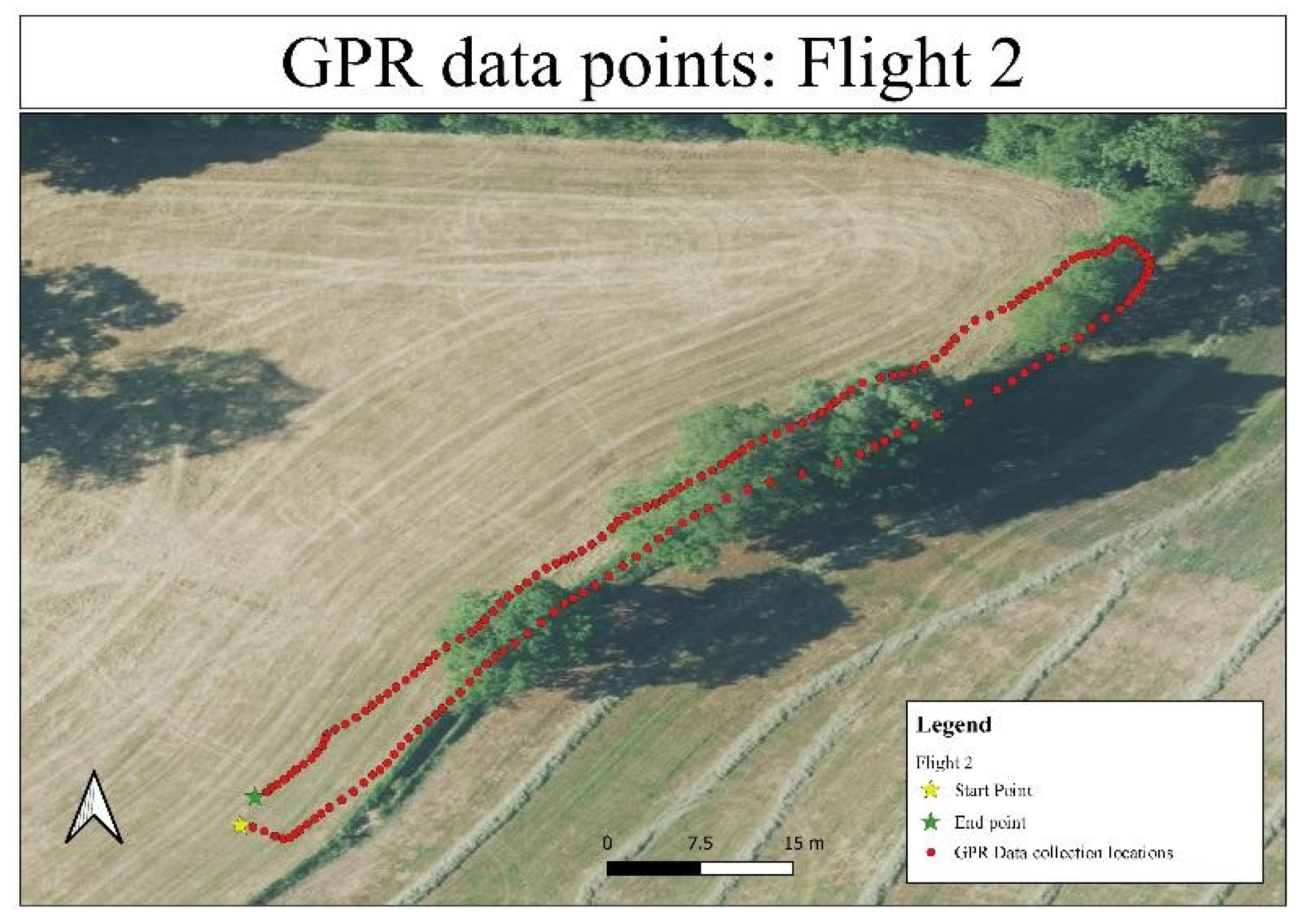
Figure 2 and Figure 4 show the spatial layout of the drone’s survey paths over the left field section, visualized on an aerial orthoimage. Red dots represent individual GPR data collection points, with a clear linear trajectory indicating a stable flight path. The yellow star marks the starting point, and the green star indicates the endpoint of the flight. The two parallel lines represent the outbound and return passes of the drone during the near-wall survey, ensuring data consistency through repeated coverage of the same area.
Figure 1.
Radargram of Flight 1 showing planar reflections between traces 7641 and 8786.
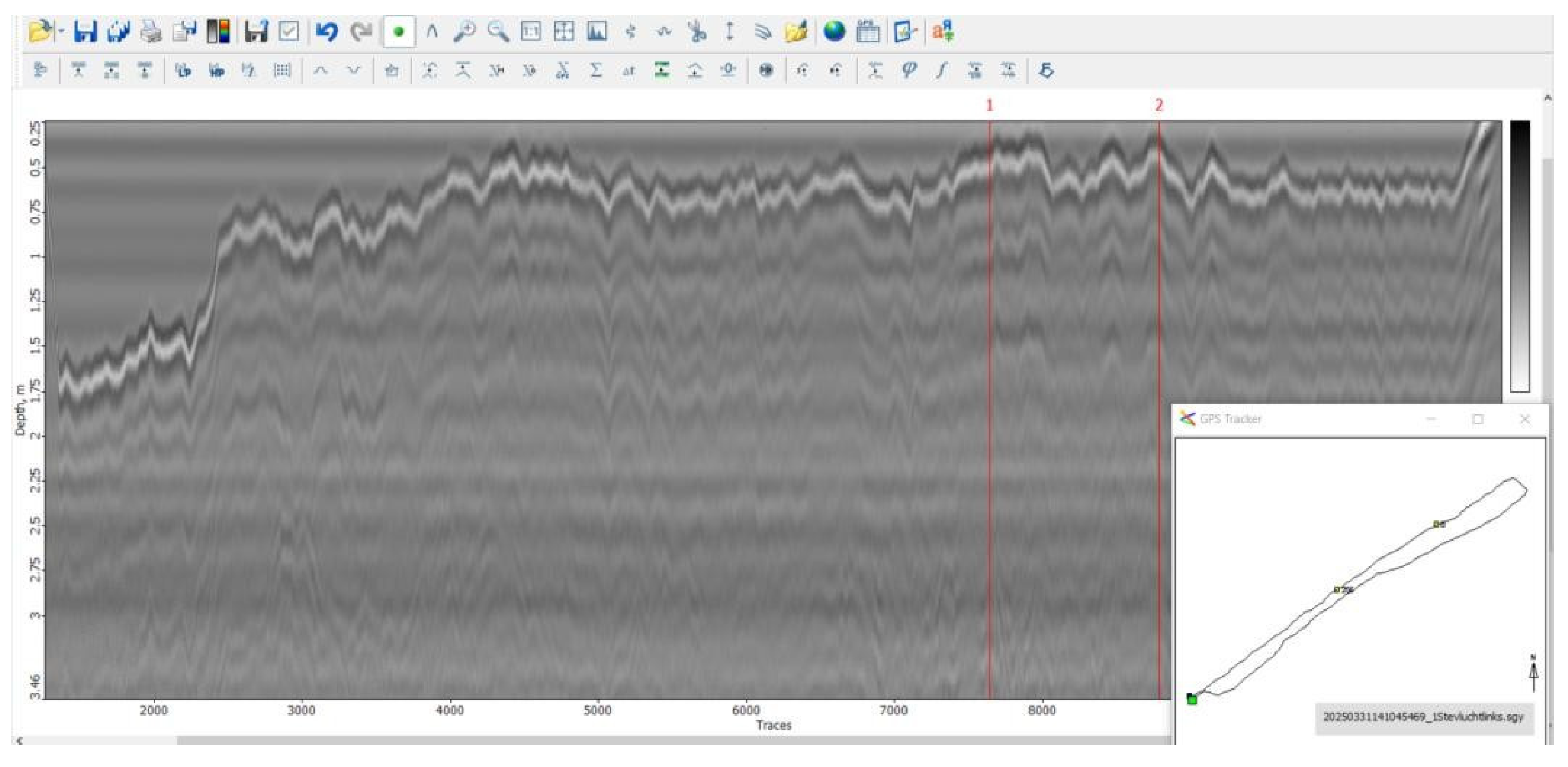
Figure 2.
Flight path and GPR data points for Flight 1.
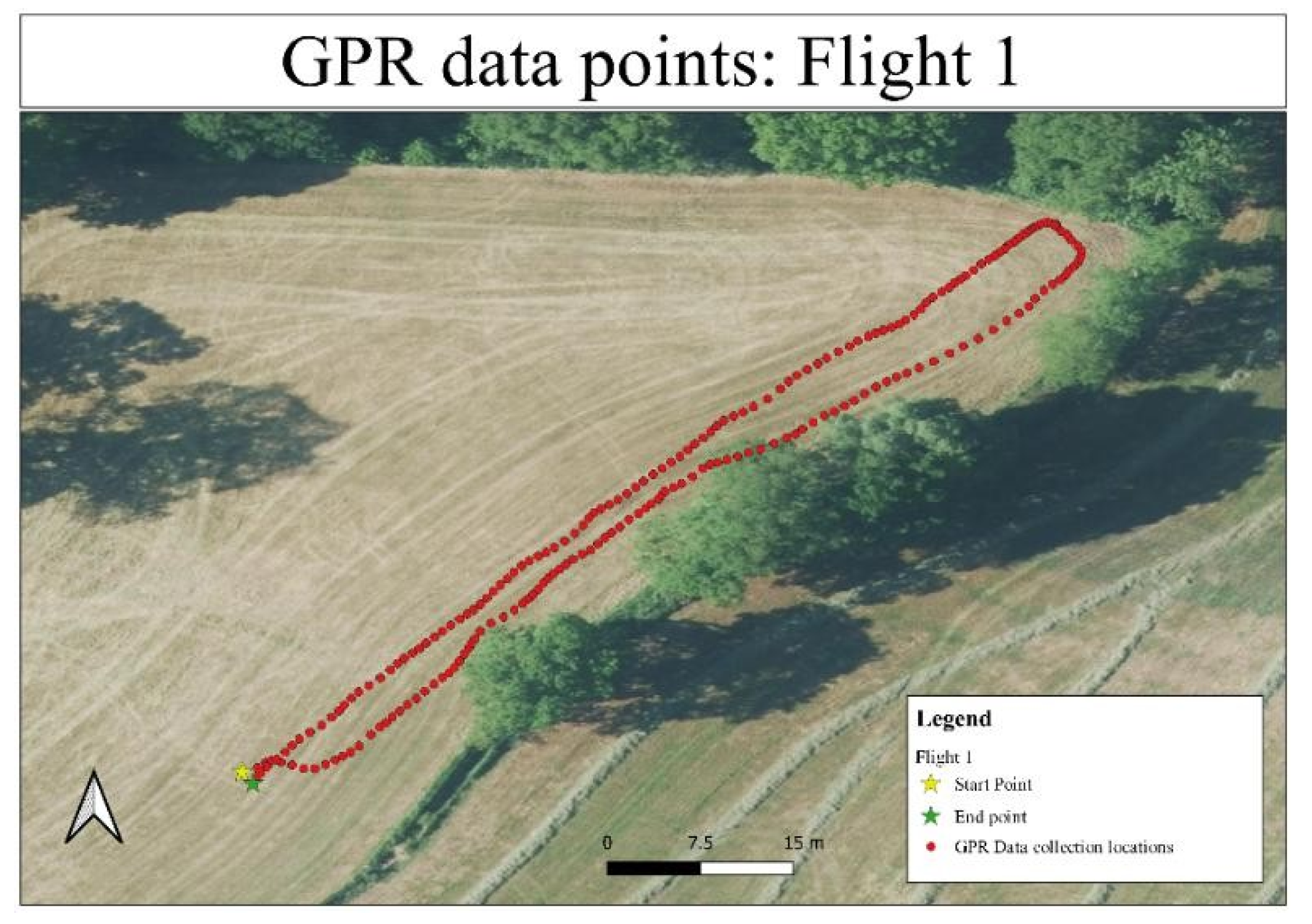
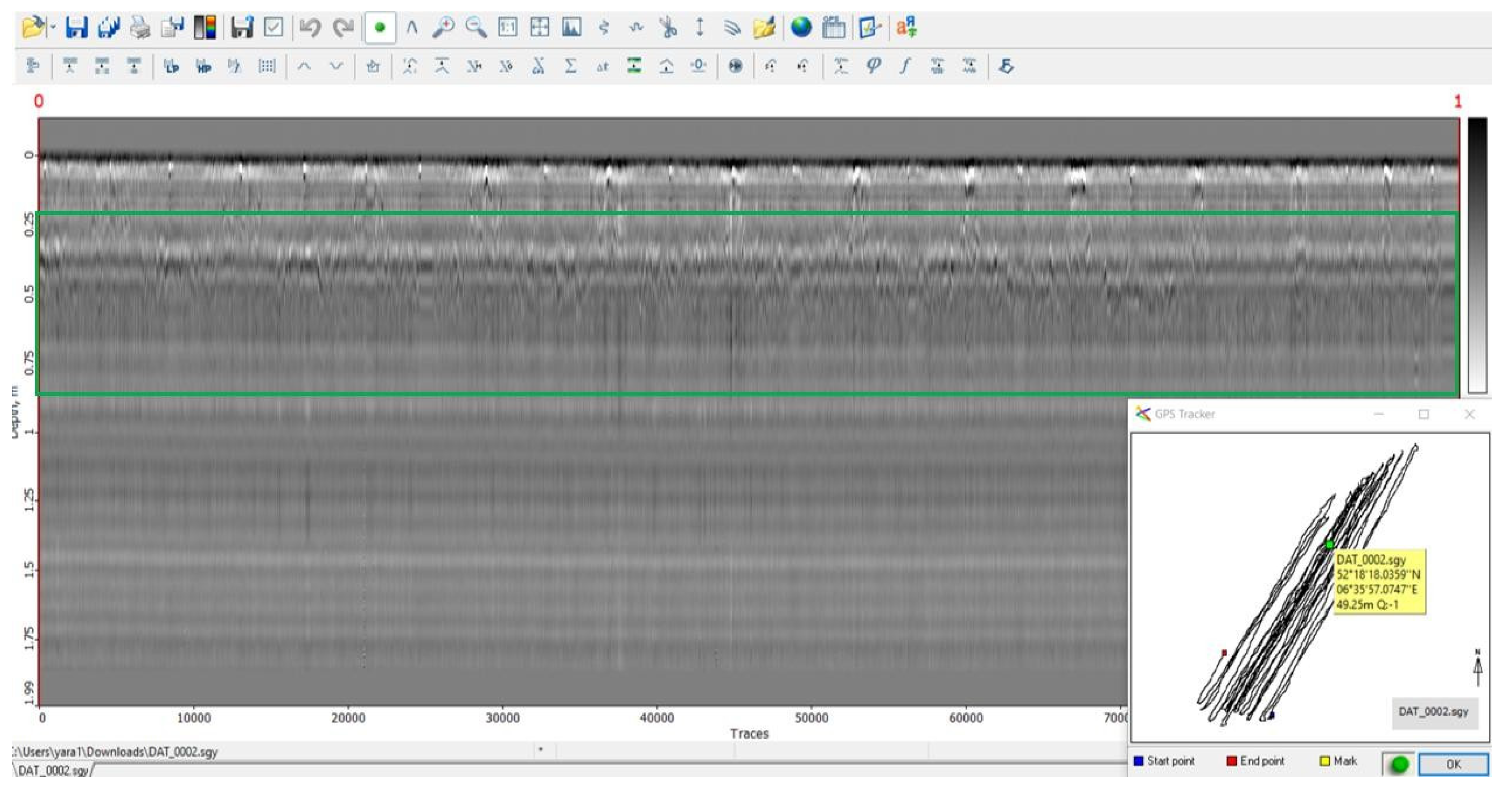
Figure 3.
Radargram of Flight 2 showing similar planar reflections.
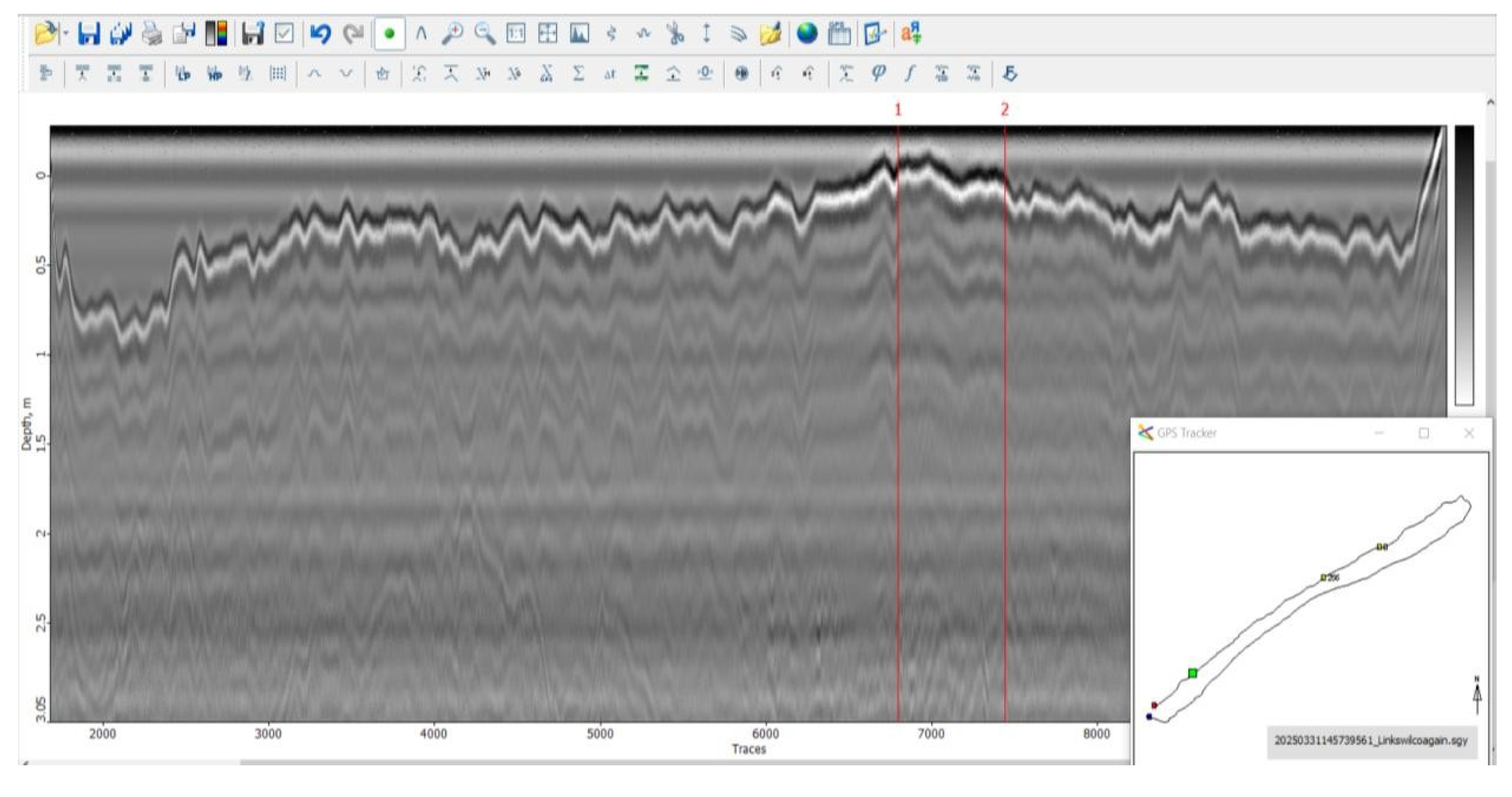
Figure 4.
Flight path and GPR data points for Flight 2.
Flight 3 (Offset Survey 2m/6m from Wall):
Flight 3, showed in Figure 5 and Figure 6, expanded the survey coverage outward from the wall. The radargram again revealed mostly uniform stratigraphy, with a slight increase in reflection amplitude between traces 4934 and 5525 at around 1.5 meters depth. This localized planar reflection may indicate subtle subsurface heterogeneity but showed no clear evidence of human-made structures.
Overall, the left field surveys indicated a geologically homogeneous area, with no strong indications of buried archaeological features.
3.1.2. Flights 4–8: Right Field and Targeted Zones
Based on historical information suggesting a higher probability for the hiding place location on the right side of the field, Flights 4 through 8 concentrated efforts in this area.
Flight 4 (Right Field Near-Wall Pass):
As presented in Figure 7 and Figure 8, two distinct planar reflection zones were detected between traces 7247 and 7842, within a shallow depth range of 0.2 to 0.6 meters. These strong, coherent reflections stand out against the surrounding stratigraphy and suggest localized subsurface anomalies potentially related to past disturbances or buried materials.
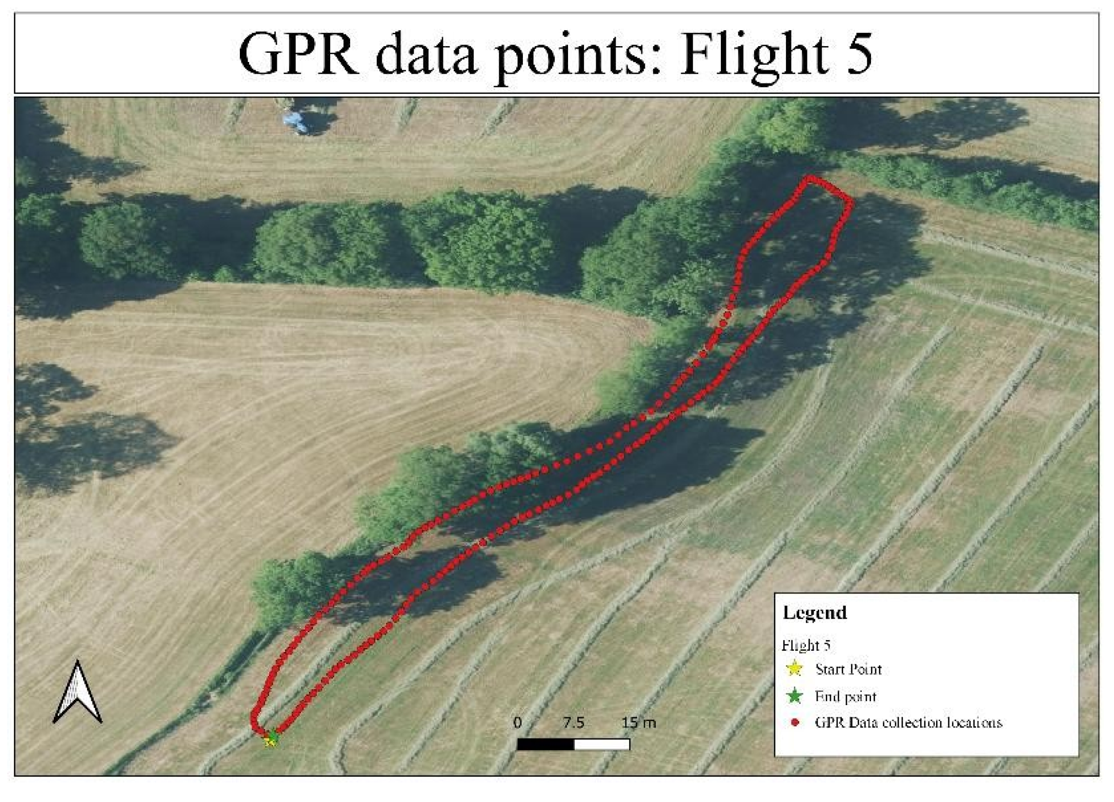
Flight 5 (Repeated Flight 4):
A second flight, as shown in Figure 10, over the same trajectory produced radargrams that lacked the clear anomalies observed in Flight 4. The data, presented in Figure 9, primarily exhibited regular stratification without distinct localized features. This discrepancy could be due to slight lateral shifts in flight path, variable soil moisture content, or natural subsurface variability.
Figure 9.
Radargram of Flight 5 with general stratification.
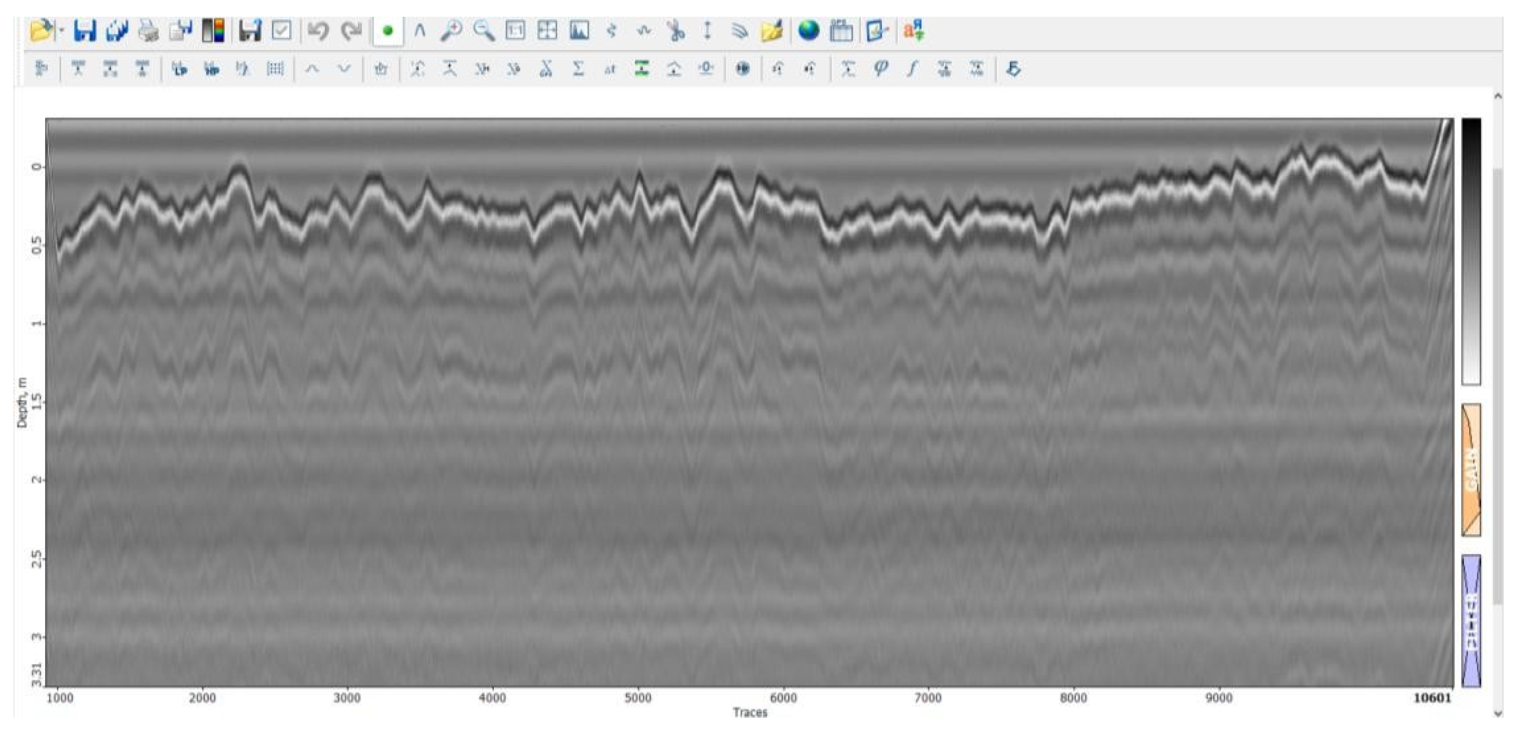
Figure 10.
Flight path and GPR data points for Flight 5.
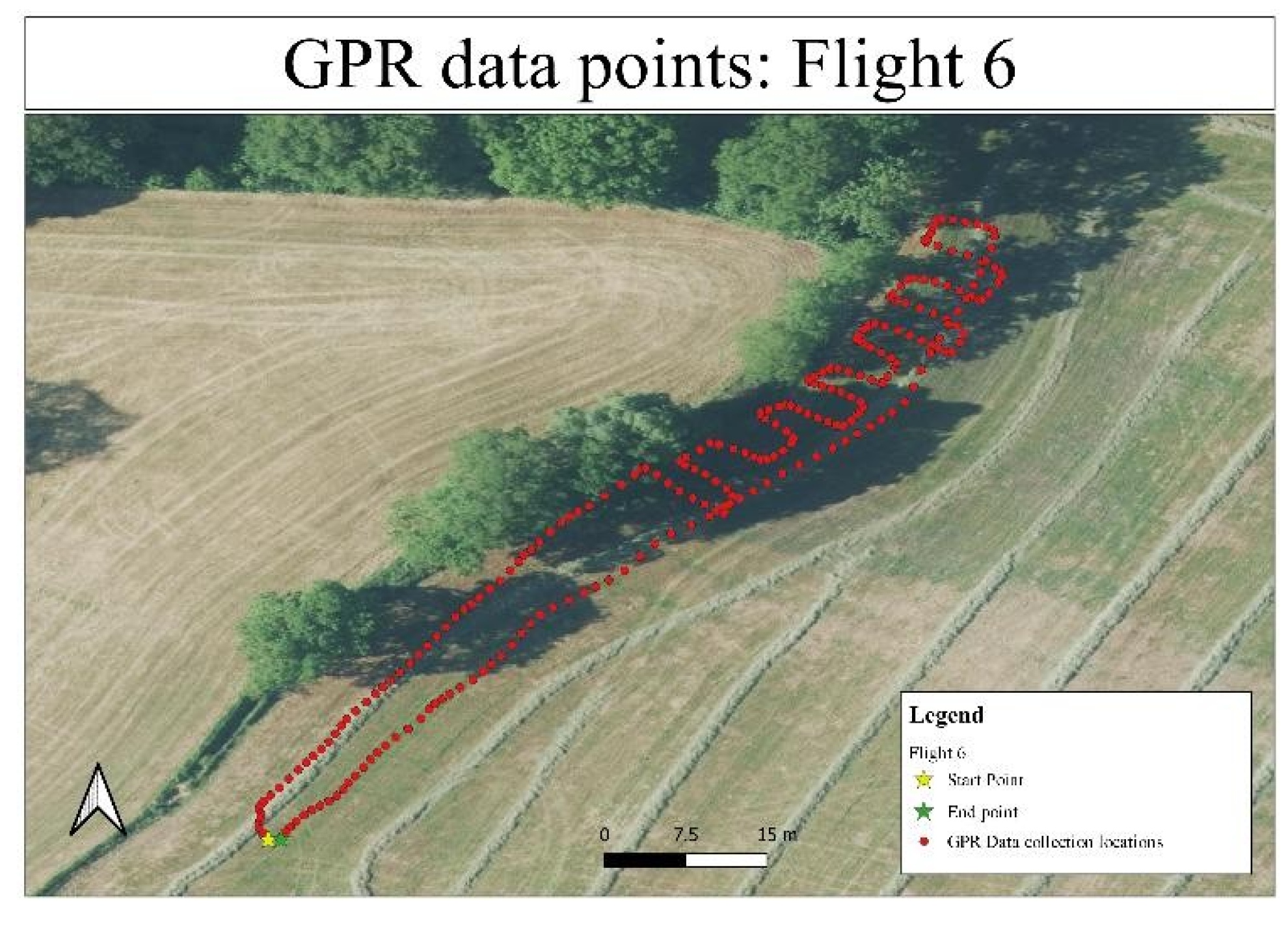
Flight 6 (Offset 2m/6m Right Field):
Offset passes, showed in Figure 12, aimed at expanding the search perimeter revealed no significant anomalies. Radargrams in Figure 11 showed continuous stratified layers, reinforcing the localized nature of the disturbances seen in Flight 4.
Figure 11.
Radargram of Flight 6 with GPS overlay.
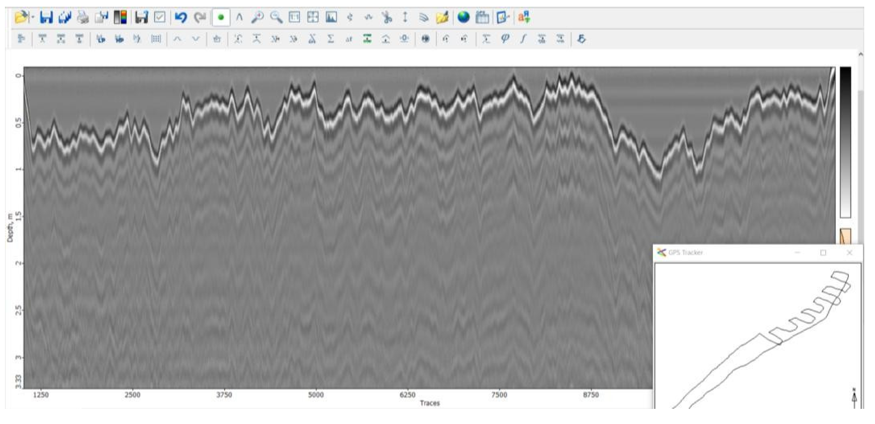
Figure 12.
Flight path and GPR data points for Flight 6.
Flight 7 (Targeted High-Probability Zone 1):
In Flight 7, presented in Figure 14, focusing on a previously identified area of interest, shallow linear reflection anomalies were observed between traces 7000 and 10,500. This can be seen in Figure 13. Although these anomalies lacked the parabolic geometry typical of voids or compact buried structures, they may indicate subtle soil disturbances or slight changes in material composition.
Figure 13.
Radargram of Flight 7 showing localized planar reflections.
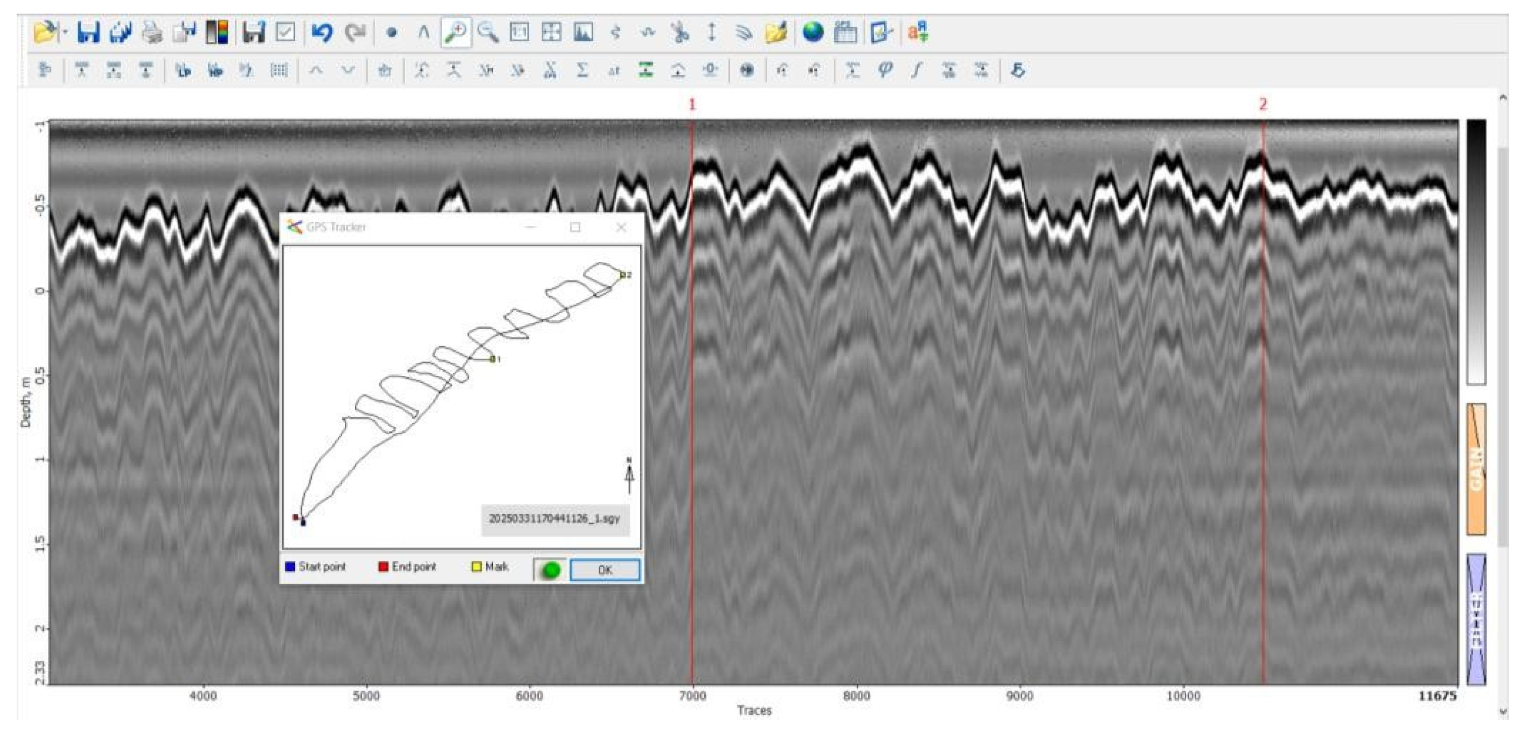
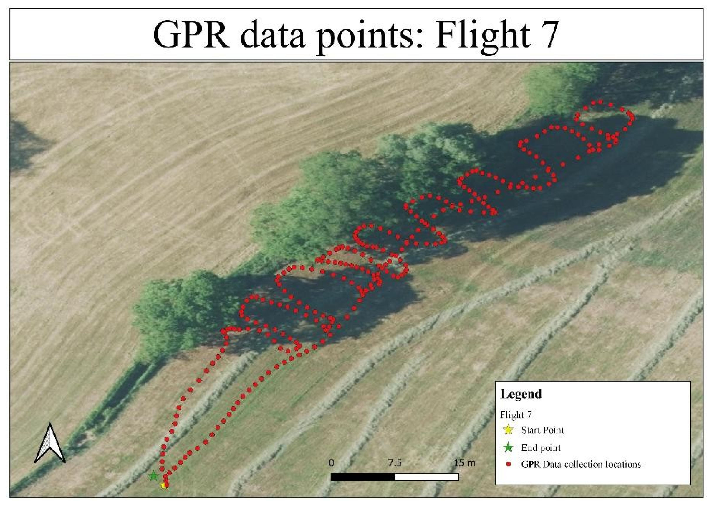
Figure 14.
Flight path and GPR data points for Flight 7.
Flight 8 (Targeted High-Probability Zone 2):
Radargrams from Flight 8, in Figure 15, were heavily attenuated, with signal strength diminishing rapidly with depth. The blurry and noisy data suggest high soil conductivity or moisture saturation, limiting the ability to detect any subsurface features. Flight path and GPR data points for Flight 8 can be seen in Figure 16.
The drone-based survey findings revealed several important observations. The surveys conducted over the left side of the field confirmed a homogeneous and undisturbed subsurface, with no significant anomalies detected throughout the investigated area. In contrast, the right side of the field produced more promising results. In particular, Flights 4 and 7 identified localized shallow planar anomalies that warrant further attention, as they may correspond to zones of historical subsurface disturbance or potential anthropogenic features. Additionally, environmental conditions significantly impacted data quality during certain flights. Flight 8, in particular, exhibited heavy signal attenuation likely due to elevated soil moisture or conductivity, highlighting the sensitivity of UAV-GPR surveys to environmental variability.
3.2. Ground-Based Survey Results
Ground-based GPR surveys were conducted to complement the UAV data and to achieve higher resolution, especially in zones where anomalies had been detected.
3.2.1. Path 1: Far Right Side
Radargrams from Path 1 in Figure 17 indicated relatively high background noise, horizontal stratification, and periodic data loss at turning points. No clear anomalies or hyperbolic reflections were detected. This suggests that, at least in this sector, the subsurface remains undisturbed.
3.2.2. Path 2: Middle Section
Path 2 radargrams in Figure 18 revealed multiple repetitive shallow hyperbolas, reaching depths of approximately 0.75 meters. The uniformity and distribution of these features strongly suggest they are associated with historical agricultural ploughing activities, rather than buried man-made structures.
3.2.3. Path 3: Tree Line Area
Surveying near the tree line in Path 3 revealed two concentrated zones of stronger reflections:
- Between traces 14,572 and 15,024.
- Between traces 17,689 and 18,130.
Both reflection zones were found at a depth of approximately 1 meter and appeared more localized and coherent than surrounding stratigraphy. These anomalies may indicate buried objects, soil disturbances, or the remnants of anthropogenic features, although confirmation would require additional methods such as coring or targeted excavation. This can be seen in Figure 19.
3.3. Summary of Findings
The combined analysis of UAV-based and ground-based GPR surveys yielded several key observations. In the left section of the field, covered by Flights 1 to 3, the subsurface stratigraphy appeared continuous and undisturbed, with no evidence of anthropogenic features detected. In contrast, the right side of the field, investigated through Flights 4 to 8, revealed more variability. Two shallow planar reflection zones detected during Flight 4, along with minor shallow anomalies observed in Flight 7, were identified as potential zones of interest for future investigation. Furthermore, Flight 8 highlighted significant limitations related to highly conductive or waterlogged soils, which caused strong signal attenuation and limited the depth of subsurface visibility.
The ground-based survey supported these findings. In the central part of the field, corresponding to Path 2, characteristic agricultural disturbance patterns were confirmed, likely resulting from historical ploughing activities. In Path 3, located adjacent to the tree line, localized subsurface anomalies were identified that differ from the surrounding stratigraphy, suggesting the presence of disturbed soil or buried features that may warrant further archaeological examination.
Although definitive evidence of the “Onderduikhol” hiding place was not found, the survey successfully delineated areas of interest for future, more invasive archaeological methods.
4. Discussion
4.1. Interpretation of Findings
The UAV-based and ground-based GPR surveys conducted near Bornerbroekseweg provided important insights into the capabilities and challenges of applying aerial geophysics for archaeological prospection. Although no definitive structural remains of the “Onderduikhol” were detected, the surveys revealed several localized anomalies that merit further investigation.
Especially noteworthy are the planar reflections detected in Flight 4 at shallow depths (0.2–0.6 meters), which are potential markers for buried features or disturbed soils. Localized, high-amplitude features are indicative of a material contrast or break in the natural stratigraphy, as might be due to the possible remain of old structures. Likewise, the minor linear patterns of reflections evident for Flight 7 as well as the two concentrated reflection bands that are present for Path 3 provide evidence for the likelihood of man-made disturbances surrounding the area of suggested historical presence.
The lack of strong hyperbolic reflections classically associated with buried objects or voids can be suggestive that if structure of the hiding place still existed, it has collapsed, was severely degraded, or was built of a type (e.g., wood, organic material) that does not yield strong GPR responses. Another possibility is that post-war land use activities, such as ploughing or reforestation, may have altered or obscured subsurface evidence.
Left field surveys (Flights 1–3) all revealed a stable, unperturbed subsurface with regular stratification. This finding corresponds with previously recorded history, which indicated lower chances of finding remains there, which consolidates the need for combining history data with the design of the surveys.
Overall, the GPR system from the UAV proved capable of identifying subtle subsurface variation over a fairly extensive area with minimal ground disturbance. Its complementary integration with a ground GPR survey provided increased spatial resolution, especially around complicated boundaries like the tree line.
4.2. Broader Implications for Archaeological UAV-GPR Surveys
The case study makes a significant contribution to the new research area of UAV-based archaeological prospection. It proves that GPR can successfully be applied from a UAV to detect shallow subsurface anomalies under optimal circumstances, offering a fast, non-destructive preliminary assessment of potential archaeological locations.
However, the study also highlights that GPR signals captured from UAV platforms can be susceptible to several environmental and operational factors, including:
- Soil composition and moisture levels influencing signal penetration and attenuation.
- Minor altitude fluctuations during flight, affecting data consistency.
- Vegetation density and surface irregularities limiting survey access or causing signal scattering.
Therefore, although UAV-GPR can be a valuable reconnaissance tool, it must be considered as part of a comprehensive multiple-method archaeological toolkit, augmenting but complemented by conventional methods such as core sampling and excavation.
4.3. Limitations
A number of constraints impacted the survey results and must be considered with caution when interpreting the results. Environmental conditions were the first of these. High conductivity and soil moisture, as noted notably with Flight 8, generated heavy signal loss and a loss of significant subsurface visibility. It is generally known that waterlogged soils or soils rich in clay have a strong ability to absorb electromagnetic signals, which reduces the effectiveness and range of GPR surveys [27,28,29,30].
Secondly, there were inherent resolution constraints within the equipment. Although the broadband nature of the Compact Broadband Detector (CBD) GPR antenna delivered a compromise between penetration depth and resolution, it may have been insufficient to resolve small-scale or deeply buried features, such as those typical of makeshift World War II hiding places.
Third, minor fluctuations in UAV altitude throughout data acquisition, even with rigorous flight planning, introduced heterogeneity in signal strength and resolution. These variations impacted inter-flight comparability and conceivably had effects on the detectability of subtle subsurface anomalies.
Finally, there is always a degree of ambiguity inherent to interpreting data. It is impossible to absolutely ascertain the nature of the detected anomalies with certainty without ground-truthing through means of soil core sampling or focused excavation. GPR is extremely useful for recognizing changes within material structure, but it cannot of its own initiate the identification of the detected changes as having an archaeological, as much as a physical, significance without additional investigative techniques.
4.4. Future Work
Based on the results of this research, we offer several directions for future research that could improve the efficacy of UAV-based GPR for detecting archaeological sites. First, targeted high-resolution scanning should be the focus of future UAV-GPR surveys, with denser, smaller-scale flight grids over areas of interest, such as the Flight 4 Path 3 anomalies. Advanced altimeters or laser-based height control technology would assist with maintaining a constant flight altitude, further enhancing quality and resolution of data.
Additionally, focused soil core sampling and stratigraphic examination of areas of detected anomalies would offer direct ground-truth validation. This is a method that would help to properly correlate GPR signals with physical subsurface features to improve the reliability of data interpretation.
Thirdly, surveys repeated at various times of year may provide some insight into the effect of seasonal variations of soil moisture content on GPR signal performance. Surveying when ground conditions are drier may minimize signal attenuation as well as improve the detectability of minor anomalies.
Lastly, combining UAV-GPR surveys with other remote sensing technologies, for example, magnetometry or electrical resistivity tomography (ERT), could substantially enhance interpretative reliability. Multi-method approaches reduce the inherent constraints of single-method surveys and provide a more comprehensive interpretation of the subsurface environment. By means of these approaches, subsequent studies can improve the practicality and effectiveness of UAV-GPR as a means of cultural heritage conservation and archaeology research.
5. Conclusions
The research involved the utilization of UAV-based ground-penetrating radar (GPR) technology for the identification of a historically valuable World War II hiding site, the “Onderduikhol,” located near Bornerbroekseweg within the municipality of Wierden, the Netherlands. Using a methodical integration of drone-borne as well as ground-based GPR surveys, the project sought to detect subsurface anomalies reflecting man-made features of the hiding structure.
Even though no conclusive evidence for the hiding place was found, the surveys were successful in identifying several localized anomalies, notably within the right portion of the field. Two shallow planar reflection zones found with the UAV survey work (Flight 4) as well as two focused reflection bands with the ground-based survey (Path 3) are areas of interest where more targeted excavation or core sampling work may be conducted.
At the same time, the research emphasized several of the inherent limitations of UAV-based GPR applications, such as susceptibility to soil conductivity and water content, difficulty in controlling flight altitude, and the problem of interpreting subtle anomalies without ground-truthing. Such challenges underscore the value of incorporating UAV-GPR within a more comprehensive, multi-method archaeology.
In conclusion, this case study presents valuable practical data regarding the possibilities and constraints of using GPR from a UAV for detecting cultural heritage sites. The experiences gained from this project lay the groundwork for the development of refined survey methods, enhancing data interpretation, and enabling the responsible conservation of cultural heritage through non-invasive means. It is recommended that future research combines high-resolution scanning, core sampling, and fusion of multiple sensors to advance the efficacy of UAV-GPR technology for application within challenging cultural heritage contexts.
Author Contributions
Conceptualization, D.R. and T.Y.K.; methodology, D.R. and T.Y.K.; software, D.R., T.Y.K., N.S., and E.G.; validation, D.R., T.Y.K., N.S., and E.G.; formal analysis, D.R., T.Y.K., N.S., and E.G.; investigation, D.R., T.Y.K., J.J., K.W., and L.L.à.N.; resources, D.R.; data curation, T.Y.K., J.J., K.W., and L.L.à.N.; writing—original draft preparation, D.R.; writing—review and editing, D.R. and T.Y.K.; visualization, N.S. and E.G.; supervision, J.K.; project administration, S.M.; funding acquisition, T.Y.K and J.K. All authors have read and agreed to the published version of the manuscript.
Funding
This research received financial support from the research group Technologies for Criminal Investigations, part of Saxion University of Applied Sciences and the Police Academy of the Netherlands. The main funding source is the KIEM scheme of Regieorgaan SIA, within the project KIEM: Integratie van Robotica en Radar.
Institutional Review Board Statement
Not applicable.
Informed Consent Statement
Not applicable.
Data Availability Statement
Data is contained within the article.
Acknowledgments
Special gratitude to Saxion University of Applied Sciences – Sustainable Areas and Soil Transitions (SAST), the Technology for Criminal Investigations (TCI) research group, and the Police Academy in the Netherlands for their collaboration and support. Special thanks to Wilko van Zijverden from SAST Saxion for providing the case and continuous support, Gerrit Allink for assisting with the initiative and coordinating all field tests, and John Altnea for contributing valuable historical insights that guided the investigation.
Conflicts of Interest
The authors declare no conflicts of interest.
References
- H. Jol, “Ground Penetrating Radar Theory and Applications | ScienceDirect.” Accessed: Apr. 27, 2025. [Online]. Available: https://www.sciencedirect.com/book/9780444533487/ground-penetrating-radar-theory-and-applications.
- L. Conyers, “Vol. 29, No. 2, 2005 of Canadian Journal of Archaeology / Journal Canadien d’Archéologie on JSTOR.” Accessed: Apr. 27, 2025. [Online]. Available: https://www.jstor.org/stable/i40048428.
- E. Utsi, “Ground-penetrating radar time-slices from North Ballachulish Moss,” Archaeol Prospect, vol. 11, no. 2, pp. 65–75, Apr. 2004. [CrossRef]
- I. Catapano, G. Ludeno, G. Gennarelli, G. Esposito, L. Crocco, and F. Soldovieri, “Ground Penetrating Radar Tomography for Cultural Heritage,” Ground Penetrating Radar: From Theoretical Endeavors to Computational Electromagnetics, Signal Processing, Antenna Design and Field Applications, pp. 97–122, Jan. 2024. [CrossRef]
- A. Arato, F. Garofalo, G. Sammartano, and A. Spanò, “Gathering GPR inspections and UAV survey in Cultural Heritage documentation context,” GISTAM 2016 - Proceedings of the 2nd International Conference on Geographical Information Systems Theory, Applications and Management, pp. 85–91, 2016. [CrossRef]
- “Remote Sensing | Special Issue: Implementation of UAV Systems for Cultural Heritage.” Accessed: Apr. 27, 2025. [Online]. Available: https://www.mdpi.com/journal/remotesensing/special_issues/E807A3WE0J.
- E. Valence, M. Baraer, E. Rosa, F. Barbecot, and C. Monty, “Drone-based ground-penetrating radar (GPR) application to snow hydrology,” Cryosphere, vol. 16, pp. 3843–3860, 2022. [CrossRef]
- D. Alexakis, R. Linck, M. Kale, A. Stele, and J. Schlechtriem, “Testing the Applicability of Drone-Based Ground-Penetrating Radar for Archaeological Prospection,” Remote Sensing 2025, Vol. 17, Page 1498, vol. 17, no. 9, p. 1498, Apr. 2025. [CrossRef]
- M. Frid and V. Frid, “A Case Study of the Integration of Ground-Based and Drone-Based Ground-Penetrating Radar (GPR) for an Archaeological Survey in Hulata (Israel): Advancements, Challenges, and Applications,” Applied Sciences 2024, Vol. 14, Page 4280, vol. 14, no. 10, p. 4280, May 2024. [CrossRef]
- A. N. Jannah, E. G. K. Paramita, S. Z. Zukhrufah, J. P. G. N. Rochman, and F. M. Azhali, “A Comparative Study of Ground-Based and Drone-Based GPR: Opportunities, Challenges, and Applications in Bromo, Indonesia,” BIO Web Conf, vol. 157, p. 05004, Feb. 2025. [CrossRef]
- “Radarteam.” Accessed: Apr. 27, 2025. [Online]. Available: http://www.radarteam.se/index.html.
- “Support for Matrice 600 Pro - DJI.” Accessed: Apr. 27, 2025. [Online]. Available: https://www.dji.com/bg/support/product/matrice600-pro.
- L. Lijcklama à Nijeholt et al., “Utilizing Drone-Based Ground-Penetrating Radar for Crime Investigations in Localizing and Identifying Clandestine Graves,” Sensors 2023, Vol. 23, Page 7119, vol. 23, no. 16, p. 7119, Aug. 2023. [CrossRef]
- M. Fisher, “Ground-Penetrating Radar Used to Uncover Mysteries beneath Our Feet,” Soil Horizons, vol. 54, no. 6, pp. 1–4, Nov. 2013. [CrossRef]
- T. B. Kelly, M. N. Angel, D. E. O’Connor, C. C. Huff, L. E. Morris, and G. D. Wach, “A novel approach to 3D modelling ground-penetrating radar (GPR) data – A case study of a cemetery and applications for criminal investigation,” Forensic Sci Int, vol. 325, p. 110882, Aug. 2021. [CrossRef]
- D. Daniels, “Ground Penetrating Radar,” Jan. 2004. [CrossRef]
- D. Goodman and S. Piro, “GPR remote sensing in archaeology,” GPR Remote Sensing in Archaeology, pp. 1–233, Jan. 2013. [CrossRef]
- C. Noviello et al., “An Overview on Down-Looking UAV-Based GPR Systems,” Remote Sensing 2022, Vol. 14, Page 3245, vol. 14, no. 14, p. 3245, Jul. 2022. [CrossRef]
- Y. Á. López, M. García-Fernández, G. Álvarez-Narciandi, and F. L. H. Andrés, “Unmanned Aerial Vehicle-Based Ground-Penetrating Radar Systems: A review,” IEEE Geosci Remote Sens Mag, vol. 10, no. 2, pp. 66–86, Jun. 2022. [CrossRef]
- “Altimeter for precise terrain following to enable drone flight at low and constant AGL.” Accessed: Apr. 27, 2025. [Online]. Available: https://www.sphengineering.com/news/altimeter-for-precise-terrain-following-to-enable-drone-flight-at-low-and-constant-agl.
- A. R. Tjoelker et al., “Drone-Based Ground-Penetrating Radar with Manual Transects for Improved Field Surveys of Buried Ice,” Remote Sens (Basel), vol. 16, no. 13, p. 2461, Jul. 2024. [CrossRef]
- “Prism2 software.” Accessed: Apr. 27, 2025. [Online]. Available: https://www.radsys.lv/en/products-soft/prism2.5+software/.
- I. Gabriela, G. Jitareanu, I. Motrescu, F. Adão, L. Pádua, and J. J. Sousa, “Evaluating Soil Degradation in Agricultural Soil with Ground-Penetrating Radar: A Systematic Review of Applications and Challenges,” Agriculture 2025, Vol. 15, Page 852, vol. 15, no. 8, p. 852, Apr. 2025. [CrossRef]
- S. Pathirana, S. Lambot, M. Krishnapillai, M. Cheema, C. Smeaton, and L. Galagedara, “Integrated ground-penetrating radar and electromagnetic induction offer a non-destructive approach to predict soil bulk density in boreal podzolic soil,” Geoderma, vol. 450, p. 117028, Oct. 2024. [CrossRef]
- Z. Li et al., “Study on Rapid Inversion of Soil Water Content from Ground-Penetrating Radar Data Based on Deep Learning,” Remote Sensing 2023, Vol. 15, Page 1906, vol. 15, no. 7, p. 1906, Apr. 2023. [CrossRef]
- Q. Lu et al., “Estimation of the Soil Water Content Using the Early Time Signal of Ground-Penetrating Radar in Heterogeneous Soil,” Remote Sensing 2023, Vol. 15, Page 3026, vol. 15, no. 12, p. 3026, Jun. 2023. [CrossRef]
- “TIPS: Estimating GPR Penetration.” Accessed: Apr. 27, 2025. [Online]. Available: https://www.sensoft.ca/blog/estimating-gpr-penetration-depth/?utm_source=chatgpt.com.
- “Factors Affecting GPR Accuracy | GPRS.” Accessed: Apr. 27, 2025. [Online]. Available: https://www.gp-radar.com/article/factors-affecting-gpr-accuracy.
- C. S. Bristow, P. C. Augustinus, I. C. Wallis, H. M. Jol, and E. J. Rhodes, “Investigation of the age and migration of reversing dunes in Antarctica using GPR and OSL, with implications for GPR on Mars,” Earth Planet Sci Lett, vol. 289, no. 1–2, pp. 30–42, Jan. 2010. [CrossRef]
- S. Pathirana, S. Lambot, M. Krishnapillai, M. Cheema, C. Smeaton, and L. Galagedara, “Ground-Penetrating Radar and Electromagnetic Induction: Challenges and Opportunities in Agriculture,” Remote Sensing 2023, Vol. 15, Page 2932, vol. 15, no. 11, p. 2932, Jun. 2023. [CrossRef]
Figure 5.
Radargram of Flight 3 with highlighted planar reflections.
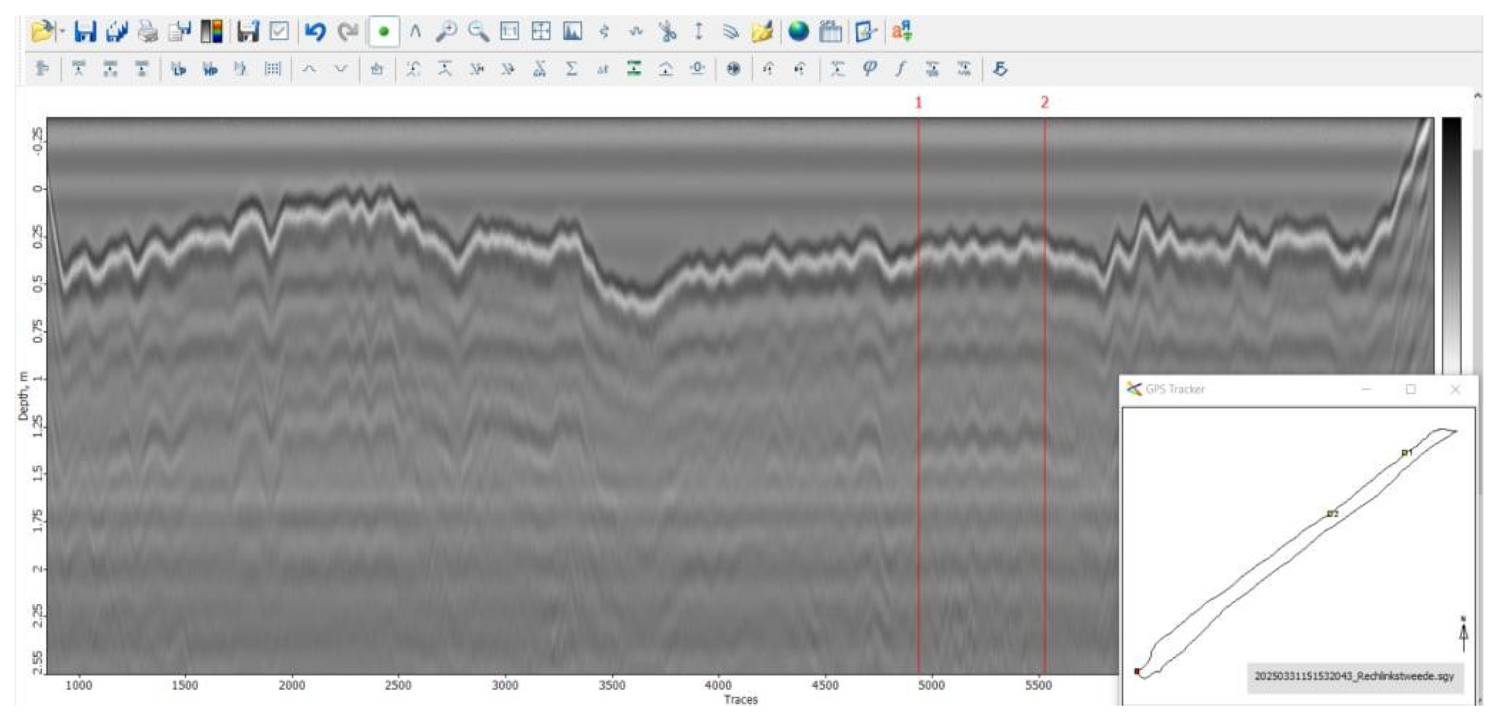
Figure 6.
Flight path and GPR data points for Flight 3.
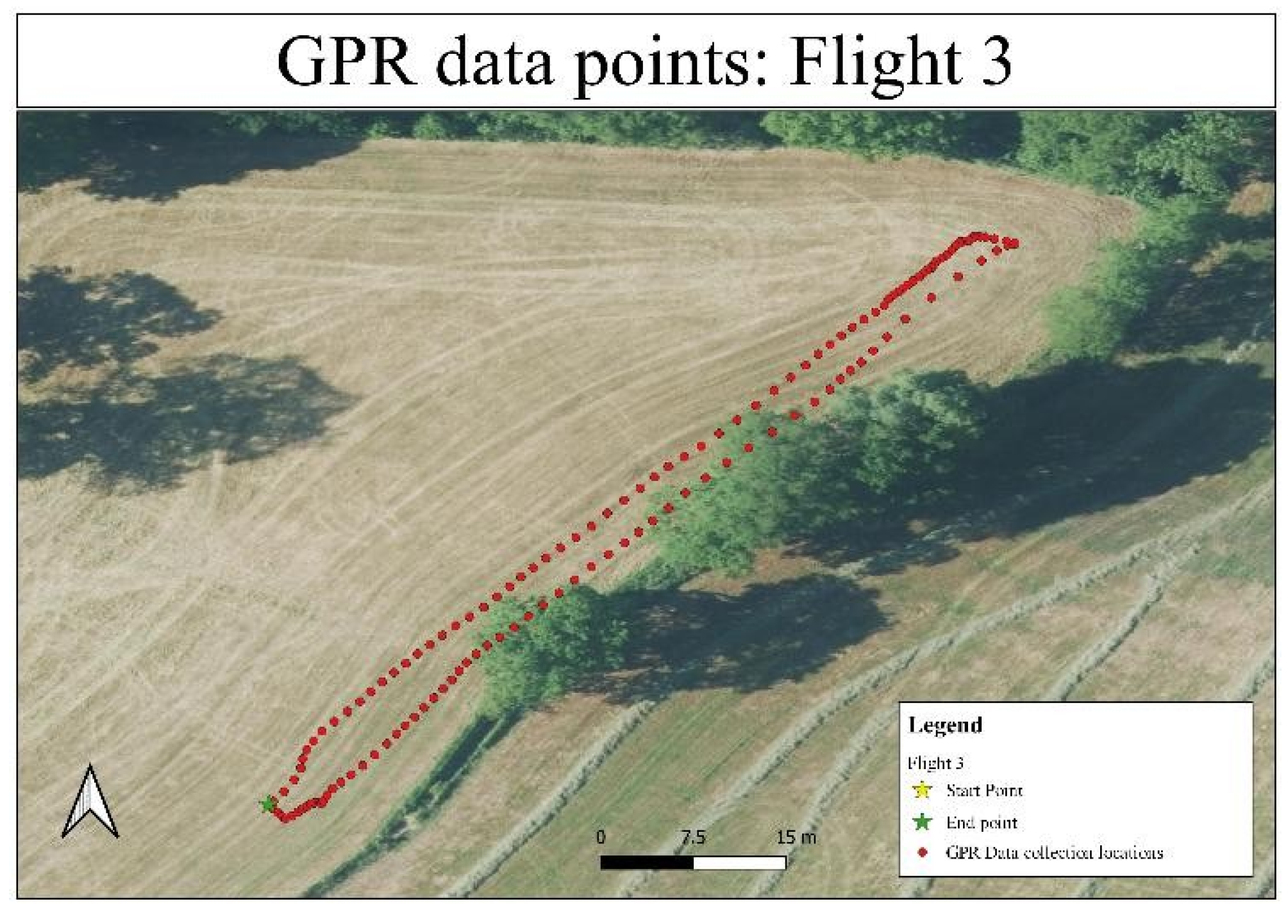
Figure 7.
Radargram of Flight 4 highlighting planar reflections at marks 1 and 2.
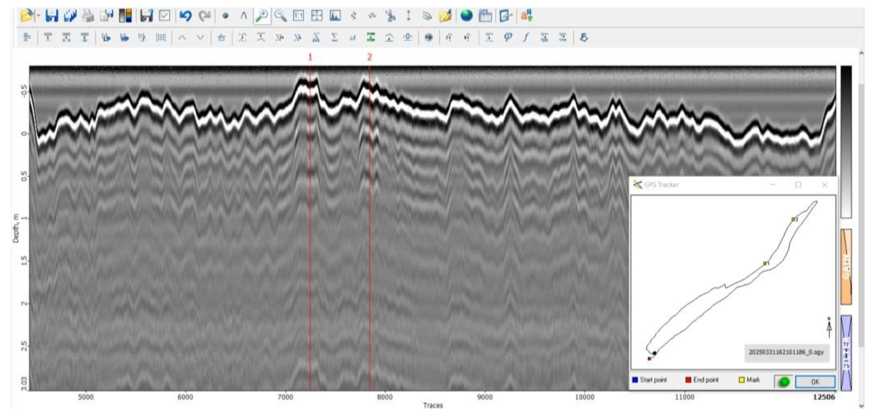
Figure 8.
Flight path and GPR data points for Flight 4.
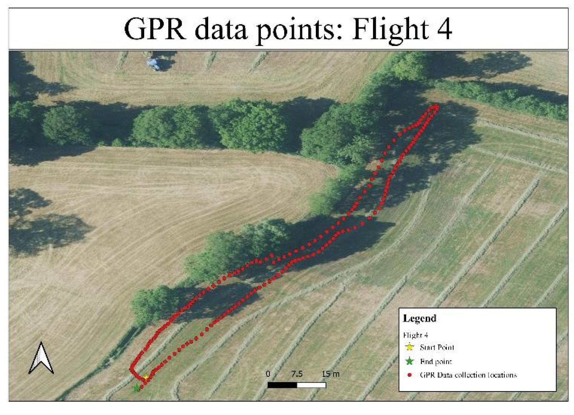
Figure 15.
Radargram of Flight 8 showing heavy signal attenuation.
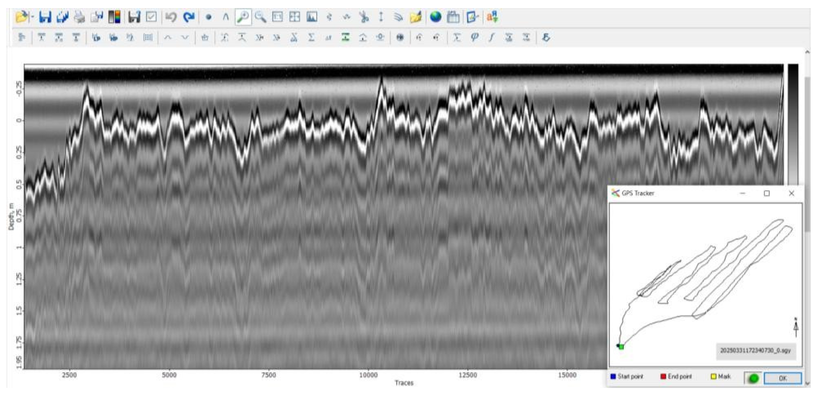
Figure 16.
Flight path and GPR data points for Flight 8.
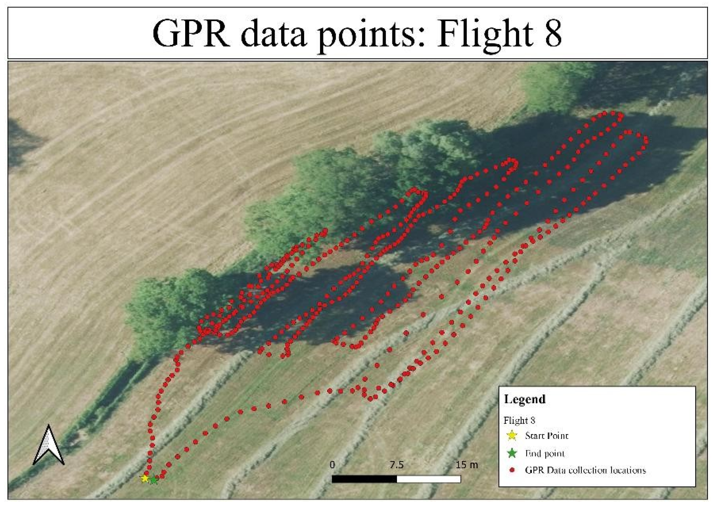
Figure 17.
Radargram of Path 1 showing background noise and data gaps.
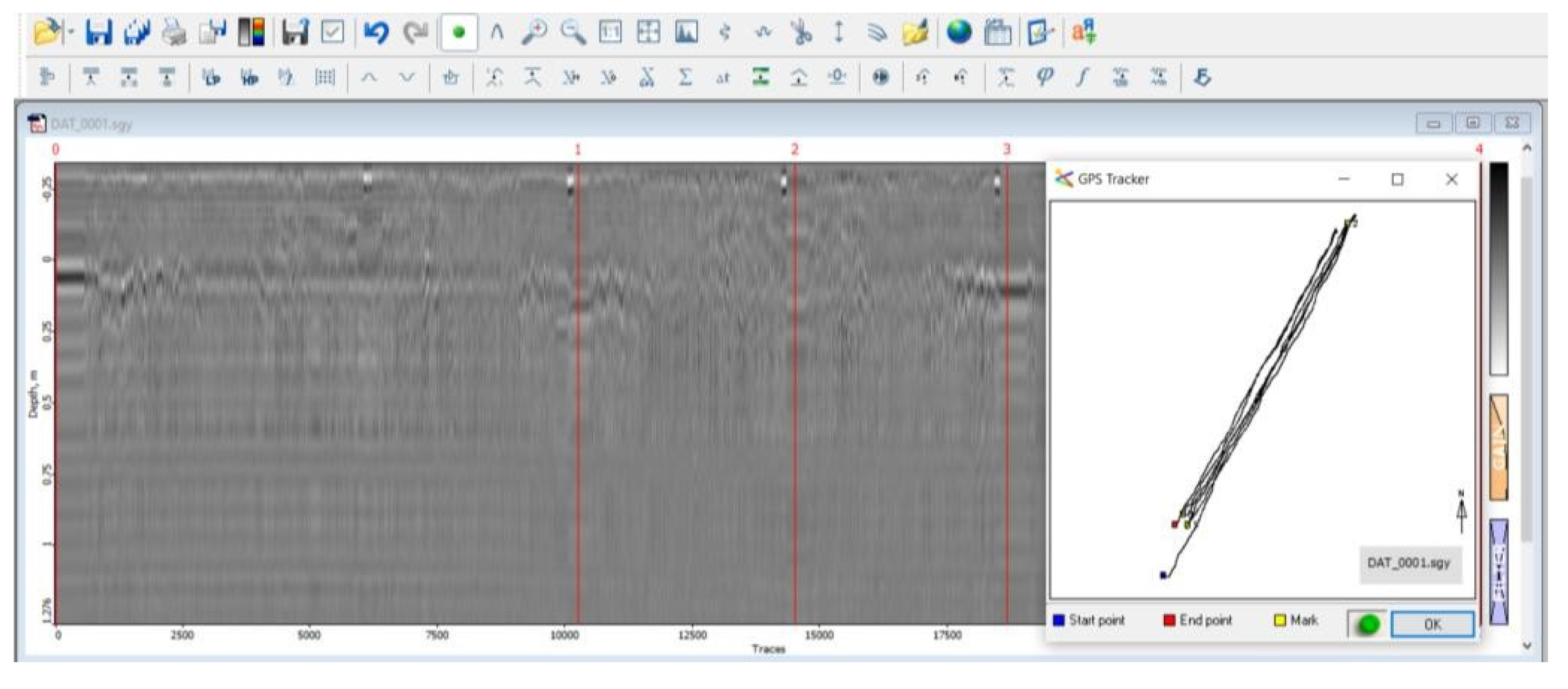
Figure 18.
Radargram of Path 2 showing hyperbolic patterns.
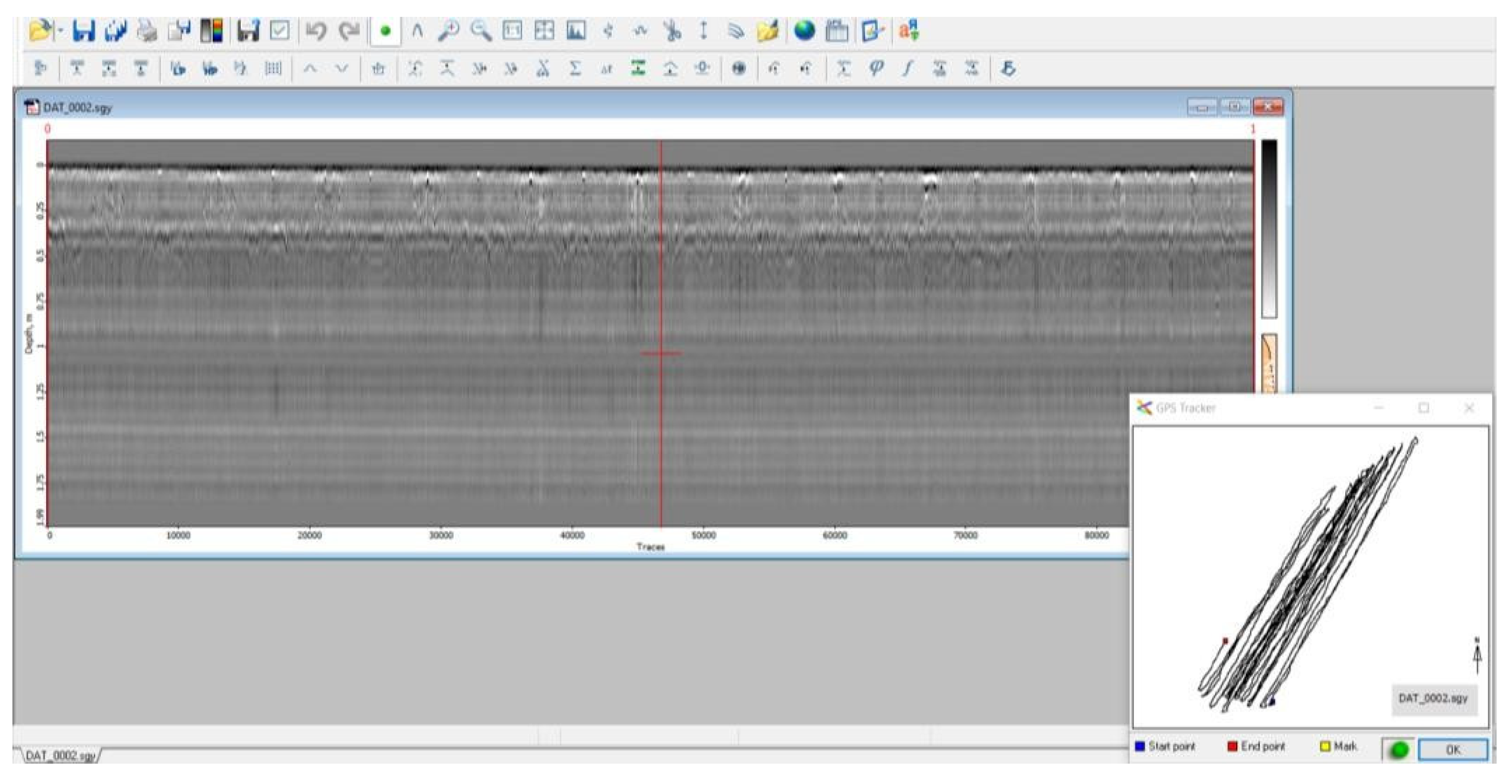
Figure 19.
Radargram of Path 3 highlighting localized reflection zones.
Disclaimer/Publisher’s Note: The statements, opinions and data contained in all publications are solely those of the individual author(s) and contributor(s) and not of MDPI and/or the editor(s). MDPI and/or the editor(s) disclaim responsibility for any injury to people or property resulting from any ideas, methods, instructions or products referred to in the content. |
© 2025 by the authors. Licensee MDPI, Basel, Switzerland. This article is an open access article distributed under the terms and conditions of the Creative Commons Attribution (CC BY) license (http://creativecommons.org/licenses/by/4.0/).
Copyright: This open access article is published under a Creative Commons CC BY 4.0 license, which permit the free download, distribution, and reuse, provided that the author and preprint are cited in any reuse.


