
Submitted:
27 April 2025
Posted:
28 April 2025
You are already at the latest version
Abstract
Recovering oil and water from palm oil mill effluent (POME) reduces environmental pollution and promotes sustainable practices. To assess the most effective recovery method, an experimental comparison was conducted between PVDF and α-Al2O3 ultrafiltration (UF) membranes at constant permeate of 20-50 LMH for PVDF and 20-70 LMH for α-Al2O3 membranes. Both membranes achieved 99.8 % chemical oxygen demand (COD) rejection, with oil concentration factor (Fo) of 186.8 % and 253.0 %, and water recovery (Rw) of 46.6 % and 60.5 %, respectively. The permeate water quality was superior to the Malaysian discharge standards, and the fat, oil, and grease (FOG) content was suitable for phase separation processes. The optimal permeate fluxes, with stable transmembrane pressures (TMP), were observed at 40 LMH (PVDF) and 60 LMH (α-Al2O3). Total resistance (Rt) values were 1.30 ×10¹² m-1 (PVDF) and 1.59 ×10¹² m-1 (α-Al2O3). The ratio of irreversible to total resistances (Rir/Rt) was 0.02 (PVDF) and 0.06 (α-Al2O3), indicating minimal irreversible fouling. Overall, the α-Al2O3 membrane demonstrated superior performance for oil and water recovery with more stable operation compared to the PVDF membrane. UF membrane technology emerges as an efficient technique for recovering oil and water compared to conventional methods.
Keywords:
Palm oil mill effluent
; Polymeric membranes
; Ceramic membranes
; Oil recovery
; Water recovery
1. Introduction
The global concern for the recovery of industrial effluents is increasing due to freshwater scarcity and environmental protection agreements [1,2,3,4]. Recently, more attention has been directed toward the discharge of oily wastewater, a major pollutant of the aquatic environment [4,5,6,7,8]. In this context, the removal of oil from palm oil industry waste streams is a major challenge, particularly in countries like Malaysia and Indonesia. Addressing this issue is crucial for developing more sustainable industrial practices [6,9]. Palm oil, identified as one of the rapidly growing industries due to its numerous product applications, continues to experience high demand [10,11]. Since 2016, global palm oil production has achieved continuous growth every year [10,12], simultaneously increasing its main brownish palm oil mill effluent (POME) [13,14].
POME is the primary waste stream generated during the processing of oil palm fresh fruit bunches (FFB) [15]. The latest reports show that global crude palm oil (CPO) production exceeded 79 million metric tons per year [16], which can be visualized by filling approximately 31,600 Olympic-sized swimming pools [17]. For every 1 ton of CPO produced, approximately 2.5 tons of POME is discharged [13]. POME typically contains 2.2 g/L - 27.2 g/L of oil and grease [18], 11.5 g/L- 79.0 g/L of total solids [18], and 894 g/L-986 g/L of water. The presence of residual oil and high organic matter in POME poses a serious environmental threat to receiving ecosystems [11]. The high organic matter content leads to elevated biological oxygen demand (BOD) and chemical oxygen demand (COD) levels in recipient surface waters. The discharge of water with high BOD and COD results in rapid microbial consumption of dissolved oxygen, leading to the formation of anaerobic, or dead, zones in the surface water [11,19]. Further information on POME generation can be found in the literature [14,20,21].
The traditional ponding system, consisting of anaerobic or aerobic ponds, is insufficient in treating POME, as it requires a large open area and fails to meet discharge requirements or prevent environmental damage caused by oil adsorption and oxygen depletion [10,22]. For instance, the open ponding system can only remove approximately 95 % of COD and BOD after a lengthy treatment period of 60 days or more [23], while the discharge requirements demand 99 % and 99.5 % removal of POME COD and BOD, respectively [14]. Moreover, the adsorption of oil residues on microbial surfaces leads to inhibition, biomass flotation, and washout of suspended solids [24]. Therefore, the presence of residual palm oil in rivers needs to be considered as a hazardous material for the environment that requires proper management [6,25,26]. At the same time, the oil content of POME holds potential value as it can serve as a raw material for products such as cosmetics, pharmaceuticals, and soap [27]. Recovered oil from POME can also be utilized as cooking oil or as concentrated feed for bioreactors, which reduces the reactor volume and surface area required for POME treatment.
The residual oil in POME can be categorized into four different particle size distributions (PSDs): free oil (>150 µm), dispersed oil mixture (20–150 µm), emulsified oil (5–20 µm), and soluble oil mixture (<5 µm) [11]. Free oil, which floats on the surface, can be easily removed using skimming or gravitational recovery technologies [11]. However, these conventional methods are insufficient for recovering oil from wastewater with low oil concentrations (i.e., < 400 ppm) and smaller oil droplets (i.e., < 20 μm) [6,28].
In addition to conventional open ponding systems [10,22], extensive research has been conducted on various technologies for treating POME, including biological wastewater treatment methods [10,22], Fenton-oxidation [29], coagulation and flocculation [30], and electrocoagulation [31,32]. Recent studies have also focused on resource recovery from POME, such as water reuse [14,33], residual oil recovery using an oil trap tank [34], and oil adsorption using polypropylene micro/nanofiber adsorbents [11]. However, the oil concentration in the effluent from these methods often exceeds the allowable discharge limits, making them unsuitable for disposal [6]. In addition, these techniques are not effective in separating low oil concentration wastewater (< 400 ppm) and smaller oil droplets (< 20 μm) [6,28]. Furthermore, these methods have limitations, including the requirement for a large operating surface area [6].
Membrane technology has proven to be a highly efficient method for recovering residual oil, achieving removal rates as high as 99.7 %, significantly outperforming conventional approaches [4,6,7,14,35,36]. Among these technologies, ultrafiltration (UF) membranes are widely used as a standalone process for wastewater treatment and recovery [6,37]. UF operates at low pressure, resulting in lower capital and operational costs compared to high-pressure membrane systems [6]. While several studies have demonstrated the effectiveness of UF in treating oily wastewater, challenges such as membrane fouling remain a concern [1,6,38]. The surface properties of the membrane play a crucial role in its antifouling performance [39]. In this line, Zhu et al. [40] demonstrated that using a hydrophilic and oleophobic hollow fiber membrane significantly enhanced UF performance in recovering oil and water from POME.
While many studies have focused on reducing the fouling of UF membranes when treating oily wastewater, fewer studies have explored the oil and water recovery efficiency across different types of UF membranes. Polymeric membranes are commonly used in oily wastewater treatment due to their low manufacturing cost, ease of processing, and low energy requirements [1,7,41]. However, they are more prone to fouling compared to ceramic membranes [1,7,41]. Ceramic membranes, on the other hand, exhibit greater resistance to fouling, easier cleaning, lower maintenance, higher thermal resistance, and greater mechanical strength compared to their polymeric counterparts [37,42,43,44]. Moreover, ceramic membranes have a longer lifespan of around 20 years, whereas polymeric membranes typically last 7 years -10 years, resulting in lower life-cycle costs [7,41]. Therefore, ceramic membranes are used in various industrial applications, not only when polymeric membranes cannot perform properly, but also where high system integrity is needed [43]. However, the higher initial capital costs of ceramic membranes have limited their adoption in certain industrial sectors, such as food and beverage and oil and gas produced waters [41]. Despite this, the water industry is increasingly recognizing ceramic membranes as a viable and cost-competitive option in the long run, leading to growing industrial interest in their applications [41,43].
Most industrial UF systems operate at a constant permeate flux to maintain a consistent production rate of permeate water [45]. This approach allows for the adjustment and control of permeate flux to maximize water production, oil concentration, and recovery while minimizing fouling [45]. Besides, UF membranes are more stable and require less frequent cleaning when operated in constant permeate flux mode compared to constant transmembrane pressure (TMP) mode [45,46]. Therefore, this study adopts the constant permeate flux mode of filtration.
While some research has been conducted on ceramic UF membranes for oily wastewater treatment [6,47], there remains a critical gap in quantitative data on the recovery of oil and water and the operational performance of POME UF using ceramic membranes compared to their polymeric counterparts. In this regard, the objectives of the present study are to (i) analyze the performances of PVDF and α-Al2O3 membranes in terms of permeate flux, rejection capacity, fouling tendency, and the efficiency of membrane cleaning to recover hydraulic permeability. (ii) determine the optimal operating conditions for both membranes within the specified range of variables, and (iii) evaluate the quality of the recovered oil and permeate water for potential reuse applications, comparing them to relevant standards.
Ceramic membranes are typically capable of operating at higher temperatures [42], presenting an opportunity for thermal energy recovery, considering that POME is typically discharged at temperatures between 80 °C - 90 °C [48]. With the collective efforts towards enhancing the sustainable practices of palm oil production and maximizing the utilization of resources in waste streams, this study serves as a foundation for future POME treatment and resource recovery.
2. Materials and Methods
2.1. POME Emulsion Preparation
In the laboratory, POME emulsion was synthesized to replicate the main characteristics, including the particle size distribution (PSD) of oil droplets and the oil content. The PSD of oil droplets in oily wastewater has been reported to have an average range of 0.8 µm -1.4 µm [49], while the oil content in POME was measured on-site and found to be in the range of 2.2 g/L - 27.2 g/L [18]. To achieve similar properties, unrefined palm oil (UPO) (KTC Edibles, United Kingdom) was mixed with demineralized water at an initial concentration of 6 g UPO/L. The mixture was heated at 55 °C and simultaneously shaken at 150 RPM using an incubator shaker (New Brunswick Innova 43, Canada) for 24 hours. To enhance the emulsion process and minimize the hydrophobic characteristics of the unrefined palm oil, the mixture was further sonicated using an energy-intensive sonifier (Branson Digital Sonifier 450, Branson Ultrasonics, United States) for 30 minutes at 40 % intensity. The mixture was left to cool down to room temperature, then sieved using a 0.103 mm sieve (INTERLAB-BV, The Netherlands) to remove large oil aggregates. The oil content was measured via COD kits (Hach Lange, United States), and the PSD of oil droplets was analyzed with a particle size analyzer (Bluewave, Microtrac, United States). POME emulsion was placed in a 10 L feed container prior to the experiments. It was used fresh for the UF experiments, after being cooled to room temperature for 2 hours - 4 hours, to prevent any degradation or alteration of its physicochemical properties.
In this study, the prepared POME emulsion represents a solids-free, pretreated version of POME to prevent rapid membrane fouling caused by the high solids content present in raw POME. Pretreatment is essential to remove solids, protect longevity and integrity of the membrane system [14,50,51,52], and focus on the recovery of oil and water during UF experiments.
2.2. Experimental Setup
Two types of tubular UF membranes were used in the present study: polymeric PVDF (Pentair, Minnesota, United States) and ceramic α-Al2O3 (Inopor, Germany). Table 1 illustrates the properties of the membranes. PVDF and α-Al2O3 membranes were installed in thermoplastic PVC-C and stainless-steel housings, respectively. Both membranes were operated in an inside-out configuration.
A laboratory-scale constant permeate flux system, compatible with both PVDF and α-Al2O3 membrane modules, was used for the experiments (Figure 1). In all cases, the POME emulsion was pumped from the feed container into the filtration system through a compact positive displacement diaphragm dosing pump (DDA12-10, Grundfos, Denmark). The permeate flux was also controlled by the same dosing pump. Crossflow velocity was regulated by an internal rotary gear circulation pump (VerderGear R, Verder B.V., the Netherlands), and monitored by a flowmeter (YF-S402, Zhongjiang energy-efficient electronics, China). After each filtration cycle, backwashing was performed for 30 seconds at a fixed pressure of 3 bar using demineralized water from a vessel connected to a compressed air system. Two pressure transducers (GS4200-USB, ESI, United Kingdom) were connected to the two sides of the membrane module to monitor the filtration pressure. The permeate water was weighed using an online digital balance (EWJ 600, Kern & Sohn GmbH, Germany). Pressure transducers and the flow rate sensor were logged during the experiments, and data were monitored and recorded in real-time using DASYLab software (version 13.0). Since the permeate pressure was under atmospheric pressure, the values displayed by the transducers were taken as the transmembrane pressure (TMP), as described in the literature [55]. Further operational details of the setup can be found in [55].
2.3. Experimental Design
2.3.1. Constant Permeate Flux Crossflow Experiments
Filtration experiments were conducted at room temperature (~22 °C) with a constant permeate flux for each test. The steady-state TMP was typically reached within 1.5 minutes-2 minutes after the start of the filtration cycle. For the PVDF membrane, the permeate flux was incrementally increased starting from 20 LMH to 50 LMH. Due to its larger pore size of 70 nm, it was expected that the α-Al2O3 membrane would exhibit higher hydraulic permeability in comparison to the PVDF membrane. Consequently, the α-Al2O3 membrane was also expected to achieve a higher optimal permeate flux. Therefore, the α-Al2O3 membrane was tested at permeate fluxes ranging from 20 LMH to 70 LMH. The maximum flux for both membranes was determined based on the stability of TMP and the maximum pressure endured by the feed pump. Table 2 provides a summary of the operational parameters for each membrane.
To determine the optimal permeate flux within the test range, the following criteria were considered: 1) maintaining the maximum TMP between 1 bar and 1.5 bar, 2) achieving the highest stable permeate flux that yields the maximum oil concentration factor (Fo) and water recovery (Rw), 3) minimizing TMP variation and irreversible fouling to reduce the frequency of chemical cleaning and extend membrane lifespan, and 4) ensuring a minimum irreversible resistance over filtration time, expressed as the ratio of irreversible to total resistances (Rir/Rt) of ≤ 0.1.
Each UF experiment consisted of three filtration cycles and two hydraulic permeability tests using demineralized water, with the first test conducted before the first filtration cycle and the second test performed after the third filtration cycle. Further details on the filtration phases and hydraulic permeability tests are available in the Supplementary Material (Section 1). Permeate water samples of the optimum UF condition were characterized. These characteristics of permeate water collected during the filtration cycles were measured in triplicates, and standard deviation was reported (Table 4).

Table 2.
Operational parameters of PVDF and α-Al2O3 membranes.
| Parameter / membrane | CFV(m/s) | Flux 1 (LMH) |
Flux 2 (LMH) |
Flux 3 (LMH) |
Flux 4 (LMH) |
| PVDF | 0.8 | 20 | 40 | 50 | - |
| α-Al2O3 | 0.8 | 20 | 40 | 60 | 70 |
2.3.2. Membrane Conditioning and Cleaning
Prior to the experiments, both PVDF and α-Al2O3 membranes were soaked in a 25 % v/v ethanol solution (Sigma-Aldrich, United States) for two hours to remove any residuals in the membrane wall and pores [56]. They were then washed with demineralized water [56].
After each UF experiment, the membranes underwent both physical and chemical cleaning. Physical cleaning involved flushing the filtration loop with demineralized water at the same crossflow velocity (CFV) used during the UF experiment until the water discharged from the outlet was clean.
For the PVDF membrane, chemical cleaning involved soaking the membrane in a 0.1 M NaOH solution (Sigma-Aldrich, United States) for 12 hours - 15 hours [56]. For the α-Al2O3 membrane, chemical cleaning was done by soaking it in a 0.75 M NaOH solution (Sigma-Aldrich, United States) while heating it at 40 °C for 12 hours -15 hours [57]. After each chemical cleaning step, the membranes were washed with demineralized water. The effectiveness of the cleaning processes in restoring the membranes’ original hydraulic permeability was analyzed and reported.
2.3.3. Membrane Performance Evaluation Methods
2.3.3.1. Rejection Capacity (Rj)
The treatment efficiency of the membranes can be directly evaluated using the rejection rate, Rj, as shown in Equation 1.
where Cp, Cfare the concentrations of parameters of interest in permeate water and feed, respectively. In this study, the rejection capacity is calculated for chemical oxygen demand (COD), total solids (TS), turbidity, and electrical conductivity (EC) of feed and permeate water.
2.3.3.2. Oil Concentration Factor (Fo)
The oil concentration factor (Fo) measures the oil concentration and indirectly indicates the potential of oil recovery from the POME concentrate. Analyzing the quality of the recovered oil through Fo helps to determine any necessary applications or post-treatments. Fo is calculated by dividing the COD ratio of the oil in the POME concentrate by that in the POME emulsion feed (g concentrate COD/g POME emulsion COD feed) (Equation 2). The COD value of the POME concentrate (CODconc.) was determined by the equation of COD balance (Equation 3). The equation represents the total COD involved before and after the filtration experiment with CODconc. calculated based on the assumption of a homogeneous POME concentrate.
where CODf is the COD of POME emulsion feed (g POME COD/L), CODconc. is the COD of the POME concentrate discharged from the filtration system (g concentrate COD/L), and CODp is the COD of the permeate water (g permeate water COD/L). is the volumetric flowrate of POME emulsion fed into the filtration system (L/min). is the volumetric flowrate of the permeate water (L/min). Vloop is the total volume (L) of the filtration system, i.e., the total internal volume of the tubes, connections, and membrane. Vloop using PVDF and Al2O3 membranes was calculated at 0.12 L and 0.13 L, respectively. tcycle is the time for each filtration cycle (15 minutes).
2.3.3.3. Water Recovery (Rw)
Rw represents the ratio of permeate water volume to the total POME emulsion feed volume (L permeate water/L POME emulsion feed) (Equation 4).
2.3.3.4. Normalized Transmembrane Pressure (TMPn)
2.3.4. Membrane Fouling Evaluation
Resistance-in-series model [56,59], using Darcy’s law (Equations 6-8), was adopted to evaluate membrane fouling via membrane resistances. Further details on this method and the equations used are available in the Supplementary Material (section 3).
where Rt (m-1) is the total resistance comprising intrinsic membrane resistance (Rm, m-1), hydraulic reversible resistance (Rr, m-1), and irreversible resistance (Rir, m-1). TMP represents the transmembrane pressure of POME emulsion filtration, and J is the permeate flux (m/s). The dynamic viscosity of the permeate water (µ) is assumed to be the same as that of pure water, 9.544×10⁻⁴ Pa·s, at the filtration temperature of 22 °C [45]. TMPn,o is the demineralized water filtration pressure before the first UF cycle. Rt was calculated based on the final filtration pressure of POME emulsion (TMPn,1) as shown in Equation 7. After backwashing, the average TMPn during the hydraulic permeability test was recorded as TMPn,2, and Rir was determined from Equation 8.
The fouling from Rir due to POME emulsion filtration was defined as the irreversible deposition or adsorption of oil aggregates onto the membrane surface and internal pores, causing some partial blocking [59]. Rir/Rt ratio was used in this study to analyze and compare the degree of irreversible fouling that occurred under each UF condition.
2.3.4.1. Hydraulic Permeability
The hydraulic permeability (Lh) was calculated using Darcy’s Law (Equation 9).
where J is the permeate flux of demineralized water (LMH), and TMPo is the transmembrane pressure (Pa) using demineralized water.
2.4. Analytical Methods
POME emulsion feed and permeate water samples were characterized in triplicates. Total and soluble chemical oxygen demand (CODt, and CODs) were determined using Hach-Lange kits (Hach Lange, United States). Fat, oil, and grease (FOG) content was directly calculated based on the measured COD of POME emulsion using the theoretical ratio of 2.71 g COD/g FOG. More details on the ratio calculation can be found in the Supplementary Material (Section 2).
pH was measured using a multi-meter (Multi 3430, WTW inoLab_IDS, Xylem Analytics, Germany), whereas electrical conductivity (EC) was measured using a digital meter (Multi 9420, WTW inoLab_IDS, Xylem Analytics, Germany). Turbidity was analyzed using a digital turbidimeter (2100N, Hach Lange, United States).
The particle size distribution of the oil droplets was determined using a particle size analyzer (S3500 Bluewave, Microtrac MRB, Germany). Total nitrogen and ammoniacal nitrogen were characterized using Hach-Lange kits (Hach Lange, United States). The measurements of total solids (TS) and total suspended solids (TSS) were performed according to the standard methods [60], whereas total dissolved solids (TDS) were calculated from the difference between TS and TSS. The analysis of these parameters is essential to assess the efficiency of the UF experiments using PVDF and α-Al2O3 membranes. Additionally, these analyses allowed for a comparison of the permeate water quality with industrial water discharge standards [61,62].
3. Results and Discussion
A comparison between PVDF and α-Al2O3 membranes was made based on various performance variables, including the rejection capacity (Rj), oil concentration factor (Fo), water recovery (Rw), the effect of permeate flux on normalized TMP (TMPn) and fouling resistances (R), and the efficiency of membranes cleaning. The key results of this comparison are summarized in Table 5.
3.1. POME Emulsion Characteristics
The physicochemical characteristics of POME emulsion compared to raw POME are presented in Table 3. POME emulsion has an acidic pH of 5.4, which is consistent with the reported literature on raw POME pH ranging from 3.4 to 5.5 [18]. The high amount of organic matter in POME emulsion can be observed by CODt of 15.0 ± 0.2 gO2/L, which is solely attributed to unrefined palm oil. Similarly, the concentration of fat, oil, and grease (FOG) in POME emulsion was found to be 5.5 ± 0.1 g/L, falling within the range of raw POME FOG values of 2.2 g/L – 27.2 g/L [18]. COD of raw POME typically exhibits a higher COD range of 15 g/L – 100 g/L [18], compared to the POME emulsion prepared in this study. Raw POME also contains other constituents such as protein (0.5 g/L – 1.6 g/L), cellulose (4.0 g/L – 14.3 g/L), lignin (9.0 g/L – 15.2 g/L), extractives (4.4 g/L – 14.5 g/L), and ash (1.2 g/L – 5.9 g/L) [18].
The turbidity of POME emulsion was measured at 580.7 ± 9.0 NTU, which is lower than the turbidity of raw POME, ranging from (65.6 – 69.4) × 103 NTU [18]. Other physicochemical characteristics of POME emulsion were also quantitatively lower than those of raw POME. For instance, EC of POME emulsion was measured at 18.3 ± 0.1 µS/cm, which is less than 137 µS/cm of raw POME [63]. Similarly, total nitrogen and ammoniacal nitrogen of POME emulsion of (5.9 ± 0.1) × 10-3 g/L, and 0.2 × 10⁻³ g/L, respectively, were lower than the respective values in raw POME ranging 0.2 – 1.7 and (17 – 254) × 10-3 g/L, respectively [18].
The presence of TDS at 1.8 ± 0.1 g/L in POME emulsion, along with EC, was associated with monovalent and divalent ions, which could be from the dissociation of FOG [59]. Moreover, TSS of 1.9 ± 0.1 g/L in POME emulsion could be attributed to the colloids and suspended organic matter [59]. Furthermore, approximately two-thirds of the droplet size of the POME emulsion was 1.54 µm, which is consistent with the average particle size of oily wastewater [49]. The synthesis of POME emulsion with such a small particle size distribution of oil droplets is crucial for investigating the efficiency of oil and water recovery using PVDF and α-Al2O3 membranes, especially considering the challenges associated with recovering emulsified and soluble oil using conventional methods [6].
Table 3.
Physicochemical characteristics of POME emulsion.
| Parameters | POME emulsion | Raw POME [18,63] |
| pH | 5.4 | 3.4 – 5.5 |
| Electrical Conductivity (µS/cm) | 18.3 ± 0.1 | 137 |
| Turbidity (NTU) | 580.7 ± 9.0 | (65.6 – 69.4) × 103 |
| CODt (g/L) | 15.0 ± 0.2 | 15 – 100 |
| CODs (g/L) | 2.1 | - |
| TS (g/L) | 3.7 ± 0.1 | 11.5 – 79.0 |
| TDSa (g/L) | 1.8 ± 0.1 | 20.6 – 41.1 |
| TSS (g/L) | 1.9 ± 0.1 | 5 – 71.3 |
| FOGb (g/L) | 5.5 ± 0.1 | 2.2 – 27.2 |
| Total nitrogen (g TN/L) | (5.9 ± 0.1) × 10-3 | 0.2 – 1.7 |
| Ammoniacal nitrogen (g NH4-N/L) | 0.2 × 10⁻³ | (17 – 254) × 10-3 |
| Particle size distribution (PSD) (µm, % v/v) | 1.54 (61.5 %), 0.04 (38.5 %) |
- |
aValue of POME emulsion was calculated from the difference between TS and TSS. bValue of POME emulsion was calculated using the ratio of 2.71 g CODt/g FOG.
3.2. Comparison on the Quality of Oil and Water Recovery
3.2.1. Rejection Capacity (Rj)
Rejection capacity for COD, turbidity, TS, and EC was analyzed at the optimum UF conditions for each membrane, as shown in Figure 2. Both membranes achieved high rejection rates for the selected parameters. Specifically, COD rejection of 99.8 % was achieved with both membranes. Similarly, PVDF and α-Al2O3 membranes removed 99.6 % and 99.9 % of turbidity, respectively. The COD rejection obtained in this study was higher than that reported in the literature [59,64,65,66]. Hernández et al. [59] reported COD rejection of 80 %-85 % and turbidity rejection of 90 %-95 % using nanofiltration (NF) membranes. Moreover, Huang et al. [67] achieved a turbidity rejection of 98.3 % for raw surface water using UF membranes. The high COD and turbidity rejections observed in this study suggest that suspended particles and colloids larger than the membrane’s pore sizes may be the primary foulants, which aligns with the findings of Huang et al. [67].
Furthermore, PVDF and α-Al2O3 membranes removed 94.0 % and 86.1 % of TS, respectively. It can be inferred that some oil droplets were smaller (0.04 µm) than the α-Al2O3 membrane pore size (0.07 µm), allowing them to pass through the membrane pores. Additionally, oil droplets may have been distorted during filtration, breaking into smaller particles that passed through the membrane pores [58]. However, rejections higher than 80 % are considered adequate [59]. Furthermore, it was anticipated that the formation of an oil layer on the membrane surface would provide additional resistance to the passage of solutes [1]. This phenomenon was observed by the increasing values of rejection capacities from the first to the third filtration cycles using both membranes.
Rejection of EC was achieved at 32.2 % and 63.4 % using PVDF and α-Al2O3 membranes, respectively. The observed low EC rejection might be attributable to the fact that UF membranes have the ability to retain only insoluble suspended solids, colloids, and soluble macromolecular substances that are larger than the membrane pore size [58,59], but not mono acids such as volatile fatty acids (VFAs) [58]. Therefore, POME emulsion was analyzed for VFAs and found that it contained 2.2 g/L – 4.6 g/L acetic acid, 0.4 g/L – 1.2 g/L propionic acid, and 0.5 g/L – 1.2 g/L butyric acid. VFAs in POME emulsion could be formed due to the breakdown of lipids during the sonication of unrefined palm oil (UPO). Nonetheless, EC rejection achieved in this study was higher than some reported values of 20 % using NF membranes [59].
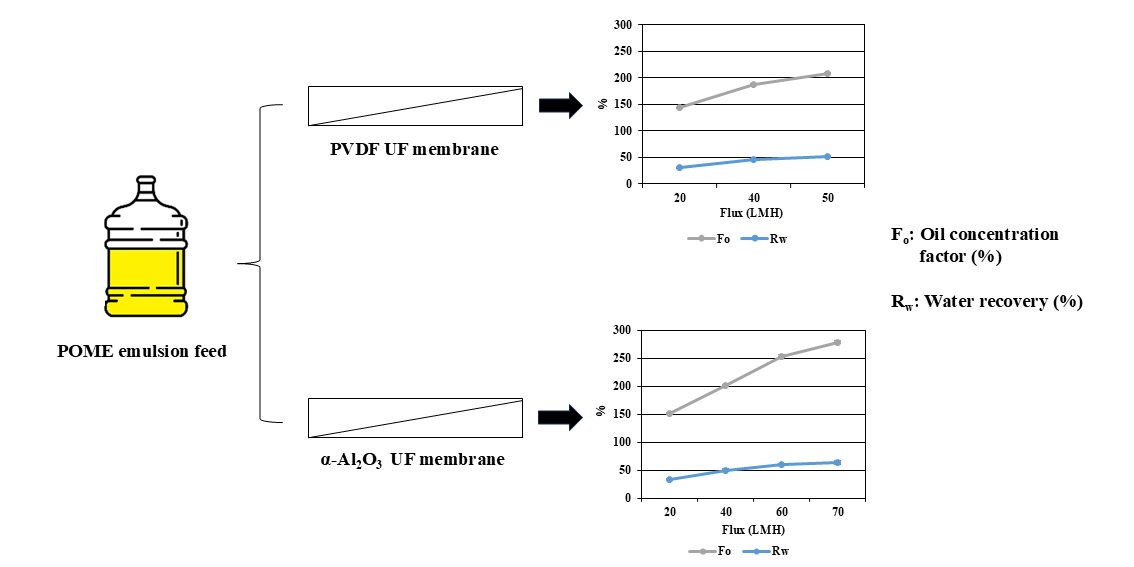
3.2.2. Oil Concentration Factor (Fo) and Water Recovery (Rw)
Fo and Rw were analyzed at the operating conditions chosen for PVDF and α-Al2O3 membranes. As illustrated in Figure 3, Fo is proportionally related to Rw for both membranes.
Figure 3 also illustrates that Fo and Rw are both influenced by the rejection of oil droplets and were found to be proportional to the permeate flux. PVDF membrane achieved Fo ranging from 143.4 % at 20 LMH to 208.6 % at 50 LMH. Consequently, Rw ranged from 30.4 % at 20 LMH to 52.2 % at 50 LMH. At the optimum condition of 40 LMH, the PVDF membrane achieved Rw of 46.6 %, resulting in Fo of 186.8 %.
Comparatively, α-Al2O3 membrane achieved Fo ranging from 150.7 % at 20 LMH to 278.6 % at 70 LMH, which resulted in Rw ranging from 33.8 % at 20 LMH to 64.1 % at 70 LMH. It can be observed that the α-Al2O3 membrane obtained higher Fo and Rw at similar UF conditions compared to the PVDF membrane. For instance, at 40 LMH, Fo and Rw of 186.8 % and 46.6 %, respectively, were achieved for the PVDF membrane and 200.9 % and 50.5 % for the α-Al2O3 membrane. At the optimum condition of 60 LMH, the α-Al2O3 membrane achieved Rw of 60.5 %, resulting in an Fo of 253.0 %. According to Ren, et al. [58], Fo of 500 % could be achieved, but it is on account of process stability i.e. constant TMPn and permeate flux over filtration time [68]. Furthermore, Fo is dependent on the feed and the membrane characteristics.
Under the optimum UF conditions, a CODconc. of 17.1 gO2/L and 20.4 gO2/L was calculated, corresponding to FOG content of 6.3 g/L and 7.5 g/L for PVDF and α-Al2O3 membranes, respectively. This observation indicates that the POME concentrate could be suitable for traditional phase separation processes (gravity separation, centrifugation, hydrocyclones, gas flotation, among others) since the oil concentration exceeds 400 ppm [6,28,37]. Another potential application for the recovered POME concentrate is biodegradation via anaerobic digestion to produce methane-rich biogas. Reducing the water content in POME emulsion by 46.6 % and 60.5 % for PVDF and α-Al2O3 membranes, respectively, can decrease the bioreactor volume and surface area, or membrane filtration area in case of membrane bioreactor application, and subsequently reduce capital and operational costs.
3.2.3. Permeate Water Characteristics
Permeate water quality characteristics at the optimum conditions of both membranes were analyzed and reported in Table 4. Moreover, industrial water discharge requirements were aimed comparing the recovered water with the global standardized requirements for industrial water discharge. Overall, the treatment of POME emulsion exhibited high COD rejection capacities ranging from 94.0 % to 99.8 % using PVDF membrane and 86.1 % to 99.8 % using α-Al2O3 membrane, as illustrated in Figure 2.
The quality of permeate water using PVDF and α-Al2O3 membranes showed low values of turbidity and COD of 0.5 – 2.5 NTU and 33.1 mg/L - 35.7 mg/L, respectively, demonstrating the retention of colloidal particles. Similar trends were observed for TS, TSS, FOG, ammoniacal nitrogen, and total nitrogen, where high retention was achieved using both membranes. A similar observation was reported in the literature for UF-RO treatment of food industry wastewater [59]. Although EC rejection was the lowest parameter, ranging from 32.2 % to 63.4 %, the permeate water still exhibited low EC values. The remaining EC in the permeate water could be attributed to the presence of volatile fatty acids and/or dissociated acids that the membranes’ MWCOs are not able to retain [59]. This was further supported by the TDS concentration in the permeate water, which reached 186.0 ± 44.2 mg/L and 488.5 ± 42.4 mg/L using PVDF and α-Al2O3 membranes, respectively. TDS could be associated with monovalent ions originating from the dissociation of FOG [59]. The slightly acidic permeate water, with a pH of 5.4 when using PVDF membranes and 6.0 with α-Al₂O₃ membranes, also contributed modestly to the observed EC value.
It is worth noting that all quality parameters are below the discharge limits of industrial water and specifically POME discharge standards, whereas pH was within the accepted range, as shown in Table 4. Therefore, the produced permeate water can be considered to have high-quality characteristics. The permeate water could be reused as boiler feed water in the palm oil mill, as service water within the mill, or potentially as a source for drinking water production [62]. It can also be discharged into the river system [62]. These findings indicate that the UF process to treat POME emulsion is a viable option for recovering clean water and oil.
Table 4.
Comparison of permeate water characteristics of POME emulsion UF using PVDF and α-Al2O3 membranes.
Table 4.
Comparison of permeate water characteristics of POME emulsion UF using PVDF and α-Al2O3 membranes.
| Parameters | Permeate water characteristics | Industrial water discharge requirements |
POME discharge standards [14,69] |
|
| PVDF membrane |
α-Al2O3 membrane |
|||
| pH | 5.4 ± 0.20 | 6.0 ± 0.1 | 6.5 – 8.5 [59,70] | 5 - 9 |
| EC (µS/cm) | 12.4 ± 0.1 | 6.7 ± 0.1 | 260 [59] | - |
| Turbidity (NTU) | 2.5 ± 0.04 | 0.5 ± 0.1 | < 5 [59] | - |
| COD (mg/L) | 35.7 ± 1.5 | 33.1 ± 1.8 | < 50 [59] | < 1000 |
| TS (mg/L) | 219.3 ± 50.0 | 509.0 ± 43 | < 1000 [59] | < 1500 |
| TSS (mg/L) | 33.3 ± 5.8 | 20.3 ± 0.6 | < 400 [70] | < 400 |
| TDSa (mg/L) | 186.0 ± 44.2 | 488.5 ± 42.4 | - | - |
| FOGb (mg/L) | 13.2 ± 0.6 | 12.2 ± 0.7 | < 50 [70] | < 50 |
| Ammoniacal nitrogen (mg NH4-N/L) |
< 0.001 | < 0.001 | - | < 100 |
| Total nitrogen (mg TN/L) | < 0.001 | < 0.001 | < 150 [70] | - |
aValue calculated from the difference between TS and TSS. bValue calculated using the ratio of 2.71 g COD/g FOG.
3.3. Comparison on the Rate of Oil and Water Recovery
3.3.1. Effect of Permeate Flux on Normalized Transmembrane Pressure (TMPn)
UF experiments at a constant permeate flux of POME emulsion were conducted using PVDF and α-Al2O3 membranes. PVDF membrane was tested at permeate fluxes of 20, 40, and 50 LMH, whereas the α-Al2O3 membrane was tested at permeate fluxes of 20 LMH, 40 LMH, 60 LMH, and 70 LMH.
Figure 4A shows that the PVDF membrane had a stable TMPn of 1.2 at both 20 LMH and 40 LMH. This observation indicated that either no fouling occurred or there was no filtration resistance from the accumulation of oil droplets. Therefore, backwash was not necessary at 20 LMH and 40 LMH, although it was performed as part of the experimental procedure. However, at 50 LMH, TMPn gradually increased in each filtration cycle, reaching about 1.5 in the second filtration cycle and exponentially increasing in the third filtration cycle, indicating serious fouling. Despite the backwash being performed after the third filtration cycle, it was not effective in stabilizing TMPn, suggesting that the fouling was irreversible. This was further supported by the high Rir/Rt ratio of 0.58 at 50 LMH, compared to 0.07 and 0.02 at 20 LMH and 40 LMH, respectively (Figure 5A).
He, et al. [71] found that for 1500 ppm soybean oil emulsions, the threshold flux for PVDF microfiltration (MF) and PS UF membranes is between 55 and 62 LMH [71]. According to He et al. [71] Stoller et al. [72], and Yang et al. [73], threshold flux is defined as the flux that separates a low fouling region, characterized by a nearly constant rate of fouling (i.e., constant TMPn), from a rapid fouling region (i.e., unstable TMPn). Therefore, it can be assumed that the threshold flux of PVDF UF membrane treating POME emulsion is approximately 50 LMH. As shown in Figure 4A and Figure 5A, 40 LMH resulted in the least variation in TMPn, and correspondingly, the lowest irreversible fouling. Therefore, in this study, 40 LMH was chosen as the optimum condition for PVDF membrane treating POME emulsion.
On the other hand, the α-Al2O3 membrane showed stable TMPn values of 1.00 at both 20 and 40 LMH, and 1.08 at 60 LMH, respectively (Figure 4B). It was further supported by the low Rir/Rt ratio of 0.01, 0.04, and 0.06 at 20 LMH, 40 LMH, and 60 LMH, respectively (Figure 5B). Oil droplets were gradually brought to the membrane surface, but crossflow shear forces enhanced back diffusion of solutes and prevented buildup, reducing concentration polarisation and minimizing oil concentration on the membrane surface [37,45]. However, at 70 LMH, there was a gradual increase in TMPn in the first and second filtration cycles, reaching 1.3, and an exponential increase in TMPn in the third filtration cycle. This sudden rise in TMPn and the ineffective backwash to stabilize TMPn indicated that serious and rapid fouling occurred due to thickening and compression of the oil layer on the membrane surface wall and a potential distortion of the deposited oil particles [58]. Oil droplets were brought to the membrane wall surface, forming a layer at a faster rate than they could be removed by the crossflow shear forces [45]. Similar TMPn evolution profiles have been reported in the literature [45,74]. The rapid increase in TMPn likely corresponded to the growth of cake formation [45], which increased the resistance of permeate water transport through the membrane pores [45]. Further details of the proposed filtration mechanism are available in the Supplementary Material (section 4, Figure A.1, Table A.4). It is also observed in Figure 5B that Rir/Rt drastically increased to 0.46 at 70 LMH. Therefore, it can be claimed that the threshold flux of α-Al2O3 membrane treating POME emulsion is approximately 70 LMH. Due to the low and stable TMPn, high fouling resistance, and low Rir/Rt ratio, the optimum condition of the α-Al2O3 membrane was selected at 60 LMH.
It is worth noting that the α-Al2O3 membrane generally had lower and more stable TMPn than the PVDF membrane at the various permeate fluxes applied. To illustrate, at the optimum condition of 40 LMH applied using PVDF membrane, TMPn reached around 1.2, compared to 1.05 using α-Al2O3 membrane at a similar condition. Furthermore, the optimum condition for the α-Al2O3 membrane was at 60 LMH, compared to 40 LMH for the PVDF membrane. This difference may be attributed to the surface properties, such as pore size, hydrophilicity, and surface charge, of PVDF and α-Al2O3 membranes [75]. It was also reported that α-Al2O3 membranes are more hydrophilic than PVDF membranes [75], indicating that α-Al2O3 membranes are less prone to fouling. These findings align with the reported literature [5,75]. These observations demonstrate the potential of each membrane and some of the key advantages of using α-Al2O3 membrane in the treatment of POME emulsion.
3.3.2. Effect of Permeate Flux on Fouling Resistances (R)
The fouling behavior of PVDF and α-Al2O3 membranes was evaluated based on the total filtration resistance (Rt) and the ratio of irreversible to total resistances (Rir/Rt). Rir and Rt were calculated using the measured TMP of each filtration condition. Figure 5 illustrates the results in terms of Rt and Rir/Rt. In addition, the filtration resistances (Rm, Rir, and Rr) for each UF condition were also calculated and reported in the Supplementary Material (Tables A.2 and A.3).
Generally, increasing the permeate flux to values below the threshold flux resulted in a decrease in the total resistance (Rt) over filtration time [58]. To illustrate, for PVDF membrane, at 20 LMH, and 40 LMH, Rt reached 1.34 × 10¹², and 1.30 ×10¹² m-1, whereas Rir/Rt ratio was 0.07 and 0.02, respectively. However, at 50 LMH, the Rt and Rir/Rt ratio increased to 2.32×10¹² m-1 and 0.58, respectively, due to the exponential increase in TMPn. The increment of filtration resistances can be attributed to pore blocking, causing a severe loss of hydraulic permeability [58].
For the α-Al2O3 membrane, Rt of 6.53 × 10¹² m-1 was observed at 20 LMH, which is higher than those of higher fluxes. This phenomenon could be attributed to the reported trend that increasing the permeate flux below the threshold flux results in decreasing the total resistance (Rt) over filtration time [58]. Interestingly, increasing the permeate flux between 40 LMH and 60 LMH resulted in a gradual decrease in Rt from 1.80 × 10¹² to 1.59 × 10¹² m-1, respectively. On the contrary, the Rir/Rt ratio slightly increased with permeate flux from 0.01 to 0.06 for permeate fluxes of 20 – 60 LMH, respectively. However, at 70 LMH, Rt increased to 2.86 × 10¹² m-1, with a rise in the Rir/Rt ratio reaching 0.46. The sudden increase of Rir/Rt ratio was supported by the exponential increase of TMPn which indicated serious fouling and a potential pore-blocking [58,76].
The rapid increase in resistance at 50 LMH for PVDF and 70 LMH for α-Al2O3 membrane could be due to the formation of an oil layer on the membrane surface [45]. During constant flux filtration, fouling appears to be a self-accelerating phenomenon [45]. Miller et al. [45] and Ognier et al. [77] reported that as the membrane pores gradually become blocked by the oil droplets, the local permeate flux in the surrounding pores must compensate to maintain a similar flux over the membrane filtration area. This increase in local permeate flux directs the oil droplets more rapidly into the other open pores, resulting in faster fouling. As more pores are blocked with oil droplets and the local permeate flux is high, cake formation occurs, causing an increase in filtration resistance.
One of the reasons that the optimum permeate flux of PVDF membrane (40 LMH) is lower than that of α-Al2O3 membrane (60 LMH) is the pore size. PVDF membrane has a pore size of 30 nm, which allows it to capture more oil particles, leading to the accumulation of oil particles on the membrane surface and a thicker oil layer. This phenomenon could cause more severe concentration polarisation on the membrane surface [37,58].
Since the selected optimum conditions for both membranes were below their selected threshold flux, the accumulation of oil layers may not contribute to the membrane resistance [45]. Similar findings were observed by Miller et al. (2014), where increasing the permeate flux did not affect the resistance of the membranes during constant flux filtration below the threshold flux of emulsified oil wastewater and whey protein using PVDF and polysulfone (PS) UF membranes [45].
3.4. Efficiency of Membrane Cleaning
PVDF and α-Al2O3 membranes were cleaned after each UF test using the cleaning methods described in section 2.4. To recover the hydraulic permeability of the α-Al2O3 membrane, a stronger chemical cleaning agent (0.75 M NaOH solution) along with heating at 40 °C was required, as the cleaning method used for the PVDF membrane (0.1 M NaOH solution) was not sufficient. The reason could be due to the higher likelihood of oil particles being distorted into the larger pores (0.07 µm) of the α-Al2O3 membrane [58], compared to the pores of the PVDF membrane (0.03 µm). It can be further supported by the measured PSD of the POME emulsion, which indicated that around 38.5 % v/v have a PSD of 0.04 µm, which is smaller than the pores of the α-Al2O3 membrane.
Figure 6 demonstrates the effectiveness of each cleaning method in recovering the hydraulic permeability of PVDF and α-Al2O3 membranes. A comparison between the initial and fouled membrane hydraulic permeability conditions was also conducted. Physical cleaning through backwashing and flushing the membranes with demineralized water was able to recover 17.4 % and 9.8 % of the hydraulic permeability of the PVDF and α-Al2O3 membranes, respectively. The low efficiency of physical cleaning can be attributed to the hydrophobic nature of the POME emulsion feed, which mainly consists of oil particles that water cannot efficiently remove. Although physical cleaning was not sufficient to fully recover the hydraulic permeability, it indicated that the fouling layer was looser in the PVDF membrane than in the α-Al2O3 membrane [1]. Chemical cleaning recovered the hydraulic permeability of both membranes, reaching over 97 %, confirming that fouling was mostly organic [78]. Additionally, a hydraulic permeability recovery of over 95 % is considered indicative of a clean membrane [1].
3.5. Comparison Summary of PVDF and α-Al2O3 Membranes Performance
Table 5 highlights the key findings of the performance comparison between PVDF and α-Al2O3 membranes to recover oil and water from POME emulsion.
Table 5.
Summary of the performance comparison between PVDF and α-Al2O3 membranes to treat POME emulsion at 40 LMH and 60 LMH, respectively.
Table 5.
Summary of the performance comparison between PVDF and α-Al2O3 membranes to treat POME emulsion at 40 LMH and 60 LMH, respectively.
| Performance variables | Experimental results | Key findings | |
| PVDF membrane | α-Al2O3 membrane | ||
| Normalized transmembrane pressure (TMPn) | 1.2 | 1.08 | α-Al2O3 membrane showed more stability and slightly less in magnitude of TMPn at a higher flux than PVDF membrane. At similar fluxes, α-Al2O3 membrane had TMPn that is lower and more stable than those of PVDF membrane. |
| Total resistance (Rt) | 1.3 ×10¹² m-1 | 1.59 ×10¹² m-1 | Both membranes showed relatively low total resistance at their respective optimum conditions. |
| Irreversible to total resistances ratio (Rir/Rt) | 0.02 | 0.06 | Both membranes demonstrated minimum irreversible fouling at their respective optimum conditions. |
| COD rejection (Rj) | 99.8 % | 99.8 % | Both membranes illustrated efficient removal of COD at their respective optimum conditions. |
| Oil concentration factor (Fo) | 186.8 % | 253.0 % | α-Al2O3 membrane achieved higher concentration of oil per filtration cycle than PVDF membrane. |
| Water recovery (Rw) | 46.6 % | 60.5 % | α-Al2O3 membrane recovered more water per filtration cycle than PVDF membrane. |
| Membrane cleaning efficiency | 97.3 % | 97.4 % | Cleaning methods used in this study achieved an efficient recovery of hydraulic permeability. |
4. Conclusions
This study provides a detailed comparative assessment of PVDF and α-Al2O3 ultrafiltration (UF) membranes for the treatment of palm oil mill effluent (POME) emulsion, with a focus on recovering both oil and water. The synthesis of POME emulsion successfully replicated the characteristics of raw POME, including a fat, oil, and grease (FOG) content of 5.5 ± 0.1 g/L and a particle size distribution (PSD) of 1.54 µm. The optimum UF conditions were determined at permeate fluxes of 40 LMH and 60 LMH using PVDF and α-Al2O3 membrane, respectively.
At these conditions, the total resistance (Rt) was found to be 1.30 ×10¹² and 1.59 ×10¹² m-1 for PVDF and α-Al2O3 membranes, respectively. Moreover, the irreversible to total resistances (Rir/Rt) ratio was calculated to be 0.02 and 0.06 for PVDF and α-Al2O3 membranes, respectively, indicating that most of the developed resistances were reversible and that no severe fouling occurred.
Both membranes demonstrated effective rejection capacity of COD, reaching 99.8 % at their respective optimum UF conditions. The FOG content in POME concentrates, reaching 6.3 g/L and 7.5 g/L for PVDF and α-Al2O3 membranes, respectively, indicated that it could be suitable for traditional phase separation processes. The produced permeate water from both UF membranes achieved high-quality standards that were superior to the global discharge requirements of POME. Therefore, the permeate water can be discharged into the river system.
The α-Al2O3 membrane showed more advantages than the PVDF membrane in treating POME emulsion at their respective optimum UF conditions. For instance, the α-Al2O3 membrane achieved an oil concentration factor (Fo) of 253 % and a water recovery (Rw) of 60.5 % at 60 LMH, whereas the PVDF membrane achieved Fo of 186.8 % and Rw of 46.6 % at 40 LMH. Moreover, α-Al2O3 membranes are more hydrophilic than PVDF membranes, indicating that α-Al2O3 membranes are less prone to fouling. Therefore, α-Al2O3 membranes exhibited lower irreversible fouling at higher flux. For these reasons, α-Al2O3 membranes are more promising regarding oil and water recovery from POME emulsion, with a more stable performance and a higher rejection capacity.
Hydraulic permeability was efficiently recovered by more than 97 % by combining physical and chemical cleaning of PVDF and α-Al2O3 membranes at 40 LMH and 60 LMH, respectively. These findings indicate that UF is a viable option for the treatment of POME emulsion, allowing for the recovery of clean water and retention of oil. The UF process for POME could represent a promising method for more sustainable wastewater management in the palm oil industry.
Supplementary Materials
The following supporting information can be downloaded at website of this paper posted on Preprints.org.
Funding
This work was supported by the TU Delft | Global Initiative (project No. 15DGF220), a program of the Delft University of Technology to boost science and technology for global development.
Conflicts of Interest
The authors declare no conflict of interest. The funders had no role in the design of the study; in the collection, analyses, or interpretation of data; in the writing of the manuscript, or in the decision to publish the results.
References
- Cifuentes-Cabezas, M.; Carbonell-Alcaina, C.; Vincent-Vela, M.C.; Mendoza-Roca, J.A.; Álvarez-Blanco, S. Comparison of different ultrafiltration membranes as first step for the recovery of phenolic compounds from olive-oil washing wastewater. Process Safety and Environmental Protection 2021, 149, 724–734. [Google Scholar] [CrossRef]
- Al-Muraisy, S.A.; Soares, L.A.; Chuayboon, S.; Ismail, S.B.; Abanades, S.; van Lier, J.B.; Lindeboom, R.E. Solar-driven steam gasification of oil palm empty fruit bunch to produce syngas: Parametric optimization via central composite design. Fuel Processing Technology 2022, 227, 107118. [Google Scholar] [CrossRef]
- Avornyo, A.; Chrysikopoulos, C.V. Applications of graphene oxide (GO) in oily wastewater treatment: Recent developments, challenges, and opportunities. Journal of Environmental Management 2024, 353, 120178. [Google Scholar] [CrossRef] [PubMed]
- Ihsanullah, I.; Bilal, M.; Sajid, M.; Mohammad, A.W.; Atieh, M.A.; Ghaffour, N. Emerging MXenes: Revolutionizing oily wastewater treatment-a comprehensive and critical review. Separation and Purification Technology 2024, 329, 125181. [Google Scholar] [CrossRef]
- Murić, A.; Petrinić, I.; Christensen, M.L. Comparison of ceramic and polymeric ultrafiltration membranes for treating wastewater from metalworking industry. Chemical Engineering Journal 2014, 255, 403–410. [Google Scholar] [CrossRef]
- Ahmad, T.; Guria, C.; Mandal, A. A review of oily wastewater treatment using ultrafiltration membrane: A parametric study to enhance the membrane performance. Journal of Water Process Engineering 2020, 36, 101289. [Google Scholar] [CrossRef]
- Romero, A.S.; Innocentini, M.D.; Oliveira, J.V.; Lider, A.; Fey, T.; Travitzky, N.; Hotza, D. Unveiling the potential of silicon carbide as a support material and membranes for oily wastewater remediation. Separation and Purification Technology 2024, 354, 129044. [Google Scholar] [CrossRef]
- Tian, Q.; Jiang, Y.; Li, Z.; Zhao, B.; Qiu, F.; Zhang, T. A dual wastes-based aerogel with inverse beetles-like structure for enhanced oily wastewater treatment. Separation and Purification Technology 2024, 333, 125896. [Google Scholar] [CrossRef]
- Sidabutar, R.; Trisakti, B.; Michael, M.; Vanness, V.; Alexander, V.; Natasya, Y.; Alamsyah, V.; Zaiyat, M.Z.Z.; Syafriandy, S.; Al Fath, M.T. Synergistic integration of zeolite engineering and fixed-bed column design for enhanced biogas upgrading: Adsorbent synthesis, CO2/CH4 separation kinetics, and regeneration assessment. Separation and Purification Technology 2025, 355, 129772. [Google Scholar] [CrossRef]
- Saad, M.S.; Wirzal, M.D.H.; Putra, Z.A. Review on current approach for treatment of palm oil mill effluent: Integrated system. Journal of Environmental Management 2021, 286, 112209. [Google Scholar] [CrossRef]
- Semilin, V.; Janaun, J.; Chung, C.H.; Touhami, D.; Haywood, S.K.; Chong, K.P.; Yaser, A.Z.; Zein, S.H. Recovery of oil from palm oil mill effluent using polypropylene micro/nanofiber. Journal of Hazardous Materials 2021, 404, 124144. [Google Scholar] [CrossRef] [PubMed]
- Hassan, M.A.; Farid, M.A.A.; Zakaria, M.R.; Ariffin, H.; Andou, Y.; Shirai, Y. Palm oil expansion in Malaysia and its countermeasures through policy window and biorefinery approach. Environmental Science & Policy 2024, 153, 103671. [Google Scholar]
- Hosseini, S.E.; Bagheri, G.; Wahid, M.A.; Saat, A. Clean fuel, clean energy conversion technology: Experimental and numerical investigation of palm oil mill effluent biogas flameless combustion. BioResources 2015, 10, 6597–6609. [Google Scholar] [CrossRef]
- Mahmod, S.S.; Takriff, M.S.; AL-Rajabi, M.M.; Abdul, P.M.; Gunny, A.A.N.; Silvamany, H.; Jahim, J.M. Water reclamation from palm oil mill effluent (POME): Recent technologies, by-product recovery, and challenges. Journal of Water Process Engineering 2023, 52, 103488. [Google Scholar] [CrossRef]
- Sadhukhan, J.; Martinez-Hernandez, E.; Murphy, R.J.; Ng, D.K.; Hassim, M.H.; Ng, K.S.; Kin, W.Y.; Jaye, I.F.M.; Hang, M.Y.L.P.; Andiappan, V. Role of bioenergy, biorefinery and bioeconomy in sustainable development: Strategic pathways for Malaysia. Renewable and Sustainable Energy Reviews 2018, 81, 1966–1987. [Google Scholar] [CrossRef]
- Soo, P.L.; Bashir, M.J.; Wong, L.-P. Recent advancements in the treatment of palm oil mill effluent (POME) using anaerobic biofilm reactors: Challenges and future perspectives. Journal of Environmental Management 2022, 320, 115750. [Google Scholar] [CrossRef]
- Gouveia, P.; Felgueiras, F.; Mourão, Z.; Fernandes, E.D.O.; Moreira, A.; Gabriel, M.F. Predicting health risk from exposure to trihalomethanes in an Olympic-size indoor swimming pool among elite swimmers and coaches. Journal of Toxicology and Environmental Health, Part A 2019, 82, 577–590. [Google Scholar] [CrossRef]
- Cheng, Y.W.; Chong, C.C.; Lam, M.K.; Leong, W.H.; Chuah, L.F.; Yusup, S.; Setiabudi, H.D.; Tang, Y.; Lim, J.W. Identification of microbial inhibitions and mitigation strategies towards cleaner bioconversions of palm oil mill effluent (POME): A review. Journal of Cleaner Production 2021, 280, 124346. [Google Scholar] [CrossRef]
- Devlin, M.; Brodie, J. Nutrients and eutrophication, in: Marine pollution–monitoring, management and mitigation, Springer, 2023, pp. 75–100.
- Yusof, M.A.B.M.; Chan, Y.J.; Chong, C.H.; Chew, C.L. Effects of operational processes and equipment in palm oil mills on characteristics of raw Palm Oil Mill Effluent (POME): A comparative study of four mills. Cleaner Waste Systems 2023, 5, 100101. [Google Scholar] [CrossRef]
- Samavati, Z.; Goh, P.S.; Ismail, A.F.; Lau, W.J.; Samavati, A.; Ng, B.C.; Abdullah, M.S. Advancements in membrane technology for efficient POME treatment: A comprehensive review and future perspectives. Journal of Environmental Sciences 2024, 155, 730–761. [Google Scholar] [CrossRef]
- Iskandar, M.J.; Baharum, A.; Anuar, F.H.; Othaman, R. Palm oil industry in South East Asia and the effluent treatment technology—A review. Environmental technology & innovation 2018, 9, 169–185. [Google Scholar]
- Cheng, Y.W.; Chong, C.C.; Lam, M.K.; Ayoub, M.; Cheng, C.K.; Lim, J.W.; Yusup, S.; Tang, Y.; Bai, J. Holistic process evaluation of non-conventional palm oil mill effluent (POME) treatment technologies: A conceptual and comparative review. Journal of Hazardous Materials 2021, 409, 124964. [Google Scholar] [CrossRef]
- Szabo-Corbacho, M.A.; Pacheco-Ruiz, S.; Míguez, D.; Hooijmans, C.M.; García, H.A.; Brdjanovic, D.; van Lier, J.B. Impact of solids retention time on the biological performance of an AnMBR treating lipid-rich synthetic dairy wastewater. Environmental Technology 2019, 1–12. [Google Scholar] [CrossRef]
- Ohimain, E.I.; Izah, S.C. A review of biogas production from palm oil mill effluents using different configurations of bioreactors. Renewable and Sustainable Energy Reviews 2017, 70, 242–253. [Google Scholar] [CrossRef]
- Choong, Y.Y.; Chou, K.W.; Norli, I. Strategies for improving biogas production of palm oil mill effluent (POME) anaerobic digestion: A critical review. Renewable and Sustainable Energy Reviews 2018, 82, 2993–3006. [Google Scholar] [CrossRef]
- Izah, S.; Oduah, A.; Ohimain, E. Effects of temperature and fermentation period on the recovery of second grade palm oil from palm press fiber. International Journal of Engineering Science and Innovative Technology 2014, 3, 131–138. [Google Scholar]
- Padaki, M.; Murali, R.S.; Abdullah, M.S.; Misdan, N.; Moslehyani, A.; Kassim, M.; Hilal, N.; Ismail, A. Membrane technology enhancement in oil–water separation. A review. Desalination 2015, 357, 197–207. [Google Scholar] [CrossRef]
- Saeed, M.O.; Azizli, K.A.M.; Isa, M.H.; Ezechi, E.H. Treatment of POME using Fenton oxidation process: Removal efficiency, optimization, and acidity condition. Desalination and Water Treatment 2016, 57, 23750–23759. [Google Scholar] [CrossRef]
- Zahrim, A.; Dexter, Z.; Joseph, C.; Hilal, N. Effective coagulation-flocculation treatment of highly polluted palm oil mill biogas plant wastewater using dual coagulants: Decolourisation, kinetics and phytotoxicity studies. Journal of water process engineering 2017, 16, 258–269. [Google Scholar] [CrossRef]
- Bashir, M.J.; Han, T.M.; Wei, L.J.; Aun, N.C.; Amr, S.S.A. Polishing of treated palm oil mill effluent (POME) from ponding system by electrocoagulation process. Water Science and Technology 2016, 73, 2704–2712. [Google Scholar] [CrossRef]
- Das, P.P.; Sharma, M.; Purkait, M.K. Recent progress on electrocoagulation process for wastewater treatment: A review. Separation and Purification Technology 2022, 292, 121058. [Google Scholar] [CrossRef]
- Azmi, N.S.; Yunos, K.F.M. Wastewater treatment of palm oil mill effluent (POME) by ultrafiltration membrane separation technique coupled with adsorption treatment as pre-treatment. Agriculture and Agricultural Science Procedia 2014, 2, 257–264. [Google Scholar] [CrossRef]
- Hosseini, S.E.; Wahid, M.A. Pollutant in palm oil production process. Journal of the Air & Waste Management Association 2015, 65, 773–781. [Google Scholar]
- Yu, L.; Han, M.; He, F. A review of treating oily wastewater. Arabian journal of chemistry 2017, 10, S1913–S1922. [Google Scholar] [CrossRef]
- Yalcinkaya, F.; Boyraz, E.; Maryska, J.; Kucerova, K. A review on membrane technology and chemical surface modification for the oily wastewater treatment. Materials 2020, 13, 493. [Google Scholar] [CrossRef] [PubMed]
- Amaral, M.C.S.; Lebron, Y.; Moreira, V. Oily wastewater treatment by membrane-assisted technologies. In Advanced Technologies in Wastewater Treatment; Elsevier, 2023, pp. 213–255.
- Salahi, A.; Abbasi, M.; Mohammadi, T. Permeate flux decline during UF of oily wastewater: Experimental and modeling. Desalination 2010, 251, 153–160. [Google Scholar] [CrossRef]
- Asatekin, A.; Mayes, A.M. Oil industry wastewater treatment with fouling resistant membranes containing amphiphilic comb copolymers. Environmental science & technology 2009, 43, 4487–4492. [Google Scholar]
- Zhu, X.; Tu, W.; Wee, K.-H.; Bai, R. Effective and low fouling oil/water separation by a novel hollow fiber membrane with both hydrophilic and oleophobic surface properties. Journal of membrane science 2014, 466, 36–44. [Google Scholar] [CrossRef]
- Alresheedi, M.T.; Barbeau, B.; Basu, O.D. Comparisons of NOM fouling and cleaning of ceramic and polymeric membranes during water treatment. Separation and Purification Technology 2019, 209, 452–460. [Google Scholar] [CrossRef]
- Wadekar, S.S.; Vidic, R.D. Comparison of ceramic and polymeric nanofiltration membranes for treatment of abandoned coal mine drainage. Desalination 2018, 440, 135–145. [Google Scholar] [CrossRef]
- Lee, S.-J.; Dilaver, M.; Park, P.-K.; Kim, J.-H. Comparative analysis of fouling characteristics of ceramic and polymeric microfiltration membranes using filtration models. Journal of Membrane Science 2013, 432, 97–105. [Google Scholar] [CrossRef]
- Subramaniam, M.; Goh, P.; Lau, W.; Tan, Y.; Ng, B.; Ismail, A. Hydrophilic hollow fiber PVDF ultrafiltration membrane incorporated with titanate nanotubes for decolourization of aerobically-treated palm oil mill effluent. Chemical Engineering Journal 2017, 316, 101–110. [Google Scholar] [CrossRef]
- Miller, D.J.; Kasemset, S.; Paul, D.R.; Freeman, B.D. Comparison of membrane fouling at constant flux and constant transmembrane pressure conditions. Journal of Membrane Science 2014, 454, 505–515. [Google Scholar] [CrossRef]
- Lv, M.; Feng, H.; Ding, Y.; Pan, S.; Qiao, H. Comparison of the formation, filtration performance, and structural characteristic of self-forming dynamic membranes under constant transmembrane pressure and constant filtration flux. Journal of Environmental Chemical Engineering 2022, 10, 108691. [Google Scholar] [CrossRef]
- Goh, P.; Ismail, A. A review on inorganic membranes for desalination and wastewater treatment. Desalination 2018, 434, 60–80. [Google Scholar] [CrossRef]
- Khadaroo, S.N.; Grassia, P.; Gouwanda, D.; Poh, P.E. Is the dewatering of Palm Oil Mill Effluent (POME) feasible? Effect of temperature on POME’s rheological properties and compressive behavior. Chemical Engineering Science 2019, 202, 519–528. [Google Scholar] [CrossRef]
- Zhong, Z.; Xing, W.; Zhang, B. Fabrication of ceramic membranes with controllable surface roughness and their applications in oil/water separation. Ceramics International 2013, 39, 4355–4361. [Google Scholar] [CrossRef]
- Xu, Y.; Li, Y.; Hou, Y. Reducing ultrafiltration membrane fouling during recycled paper mill wastewater treatment using pretreatment technologies: A comparison between coagulation and Fenton. Journal of Chemical Technology & Biotechnology 2019, 94, 804–811. [Google Scholar]
- Moser, P.B.; Ricci, B.C.; Reis, B.G.; Neta, L.S.; Cerqueira, A.C.; Amaral, M.C. Effect of MBR-H2O2/UV Hybrid pre-treatment on nanofiltration performance for the treatment of petroleum refinery wastewater. Separation and Purification Technology 2018, 192, 176–184. [Google Scholar] [CrossRef]
- Elhady, S.; Bassyouni, M.; Mansour, R.A.; Elzahar, M.H.; Abdel-Hamid, S.; Elhenawy, Y.; Saleh, M.Y. Oily wastewater treatment using polyamide thin film composite membrane technology. Membranes 2020, 10, 84. [Google Scholar] [CrossRef]
- Nguyen, M.; Loulergue, P.; Karpel, N.; Teychene, B. Electron beam irradiation of polyvinylidene fluoride/polyvinylpyrrolidone ultrafiltration membrane in presence of zwitterions molecules evaluation of filtration performances. Radiation Physics and Chemistry 2019, 159, 101–110. [Google Scholar] [CrossRef]
- Kobayashi, Y.; Yasuda, Y.; Morita, T. Low-temperature synthesis of α-alumina based on sol-gel processes. Advances in Materials and Processing Technologies 2020, 1–32. [Google Scholar] [CrossRef]
- Chen, M.; Shang, R.; Sberna, P.M.; Luiten-Olieman, M.W.; Rietveld, L.C.; Heijman, S.G. Highly permeable silicon carbide-alumina ultrafiltration membranes for oil-in-water filtration produced with low-pressure chemical vapor deposition. Separation and Purification Technology 2020, 253, 117496. [Google Scholar] [CrossRef]
- Xing, J.; Liang, H.; Chuah, C.J.; Bao, Y.; Luo, X.; Wang, T.; Wang, J.; Li, G.; Snyder, S.A. Insight into Fe (II)/UV/chlorine pretreatment for reducing ultrafiltration (UF) membrane fouling: Effects of different natural organic fractions and comparison with coagulation. Water research 2019, 167, 115112. [Google Scholar] [CrossRef] [PubMed]
- Elmaleh, S.; Abdelmoumni, L. Cross-flow filtration of an anaerobic methanogenic suspension. Journal of Membrane Science 1997, 131, 261–274. [Google Scholar] [CrossRef]
- Ren, Q.; Chen, X.; Yumminaga, Y.; Wang, N.; Yan, W.; Li, Y.; Liu, L.; Shi, J. Effect of operating conditions on the performance of multichannel ceramic ultrafiltration membranes for cattle wastewater treatment. Journal of Water Process Engineering 2021, 41, 102102. [Google Scholar] [CrossRef]
- Hernández, K.; Muro, C.; Ortega, R.E.; Velazquez, S.; Riera, F. Water recovery by treatment of food industry wastewater using membrane processes. Environmental technology 2021, 42, 775–788. [Google Scholar] [CrossRef] [PubMed]
- APHA, Standard methods for the examination of water and wastewater. APHA, American Water Works Association and Water Environment Federation, 21st ed.; American Public Health Association: Washington, DC, USA, 2005. [Google Scholar]
- Rupani, P.F.; Singh, R.P.; Ibrahim, M.H.; Esa, N. Review of current palm oil mill effluent (POME) treatment methods: Vermicomposting as a sustainable practice. World Applied Sciences Journal 2010, 11, 70–81. [Google Scholar]
- Ahmad, A.L.; Ismail, S.; Bhatia, S. Water recycling from palm oil mill effluent (POME) using membrane technology. Desalination 2003, 157, 87–95. [Google Scholar] [CrossRef]
- Okogbenin, O.; Anisiobi, G.; Okogbenin, E.; Okunwaye, T.; Ojieabu, A. Microbiological assessment and physiochemical parameters of palm oil mill effluent collected in a local mill in Ovia North East area of Edo State, Nigeria. Herald Journal of Microbiology and Biotechnology 2014, 1, 001–009. [Google Scholar]
- Kanani, D.M.; Sun, X.; Ghosh, R. Reversible and irreversible membrane fouling during in-line microfiltration of concentrated protein solutions. Journal of Membrane Science 2008, 315, 1–10. [Google Scholar] [CrossRef]
- Bennani, C.F.; Ousji, B.; Ennigrou, D.J. Reclamation of dairy wastewater using ultrafiltration process. Desalination and Water Treatment 2015, 55, 297–303. [Google Scholar] [CrossRef]
- Bortoluzzi, A.C.; Faitão, J.A.; Di Luccio, M.; Dallago, R.M.; Steffens, J.; Zabot, G.L.; Tres, M.V. Dairy wastewater treatment using integrated membrane systems. Journal of environmental chemical engineering 2017, 5, 4819–4827. [Google Scholar] [CrossRef]
- Huang, B.; Gu, H.; Xiao, K.; Qu, F.; Yu, H.; Wei, C. Fouling mechanisms analysis via combined fouling models for surface water ultrafiltration process. Membranes 2020, 10, 149. [Google Scholar] [CrossRef]
- Guo, C.; Chang, H.; Liu, B.; He, Q.; Xiong, B.; Kumar, M.; Zydney, A.L. A combined ultrafiltration–reverse osmosis process for external reuse of Weiyuan shale gas flowback and produced water. Environmental Science: Water Research & Technology 2018, 4, 942–955. [Google Scholar]
- Kamyab, H.; Chelliapan, S.; Din, M.F.M.; Rezania, S.; Khademi, T.; Kumar, A. Palm oil mill effluent as an environmental pollutant. Palm oil 2018, 13, 13–28. [Google Scholar]
- Azmi, N.S.; Yunos, K.F.M.; Baharuddin, A.S.; Dom, Z.M. The effect of operating parameters on ultrafiltration and reverse osmosis of palm oil mill effluent for reclamation and reuse of water. BioResources 2013, 8, 76–87. [Google Scholar] [CrossRef]
- He, Z.; Miller, D.J.; Kasemset, S.; Paul, D.R.; Freeman, B.D. The effect of permeate flux on membrane fouling during microfiltration of oily water. Journal of membrane science 2017, 525, 25–34. [Google Scholar] [CrossRef]
- Stoller, M.; Ochando-Pulido, J.M. About merging threshold and critical flux concepts into a single one: The boundary flux. The Scientific World Journal 2014, 2014. [Google Scholar] [CrossRef]
- Yang, Q.; Luo, J.; Guo, S.; Hang, X.; Chen, X.; Wan, Y. Threshold flux in concentration mode: Fouling control during clarification of molasses by ultrafiltration. Journal of Membrane Science 2019, 586, 130–139. [Google Scholar] [CrossRef]
- Cai, Z.; Wee, C.; Benjamin, M.M. Fouling mechanisms in low-pressure membrane filtration in the presence of an adsorbent cake layer. Journal of Membrane Science 2013, 433, 32–38. [Google Scholar] [CrossRef]
- Jeong, Y.; Kim, Y.; Jin, Y.; Hong, S.; Park, C. Comparison of filtration and treatment performance between polymeric and ceramic membranes in anaerobic membrane bioreactor treatment of domestic wastewater. Separation and Purification Technology 2018, 199, 182–188. [Google Scholar] [CrossRef]
- Lv, J.; Zhang, G.; Zhang, H.; Zhao, C.; Yang, F. Improvement of antifouling performances for modified PVDF ultrafiltration membrane with hydrophilic cellulose nanocrystal. Applied Surface Science 2018, 440, 1091–1100. [Google Scholar] [CrossRef]
- Ognier, S.; Wisniewski, C.; Grasmick, A. Membrane bioreactor fouling in sub-critical filtration conditions: A local critical flux concept. Journal of membrane Science 2004, 229, 171–177. [Google Scholar] [CrossRef]
- Dereli, R.K.; Heffernan, B.; Grelot, A.; van der Zee, F.P.; van Lier, J.B. Influence of high lipid containing wastewater on filtration performance and fouling in AnMBRs operated at different solids retention times. Separation and Purification Technology 2015, 139, 43–52. [Google Scholar] [CrossRef]
Figure 1.
Schematic diagram of the ultrafiltration (UF) setup of POME emulsion using PVDF and α-Al2O3 membranes at a crossflow velocity (CFV) of 0.8 m/s.
Figure 1.
Schematic diagram of the ultrafiltration (UF) setup of POME emulsion using PVDF and α-Al2O3 membranes at a crossflow velocity (CFV) of 0.8 m/s.
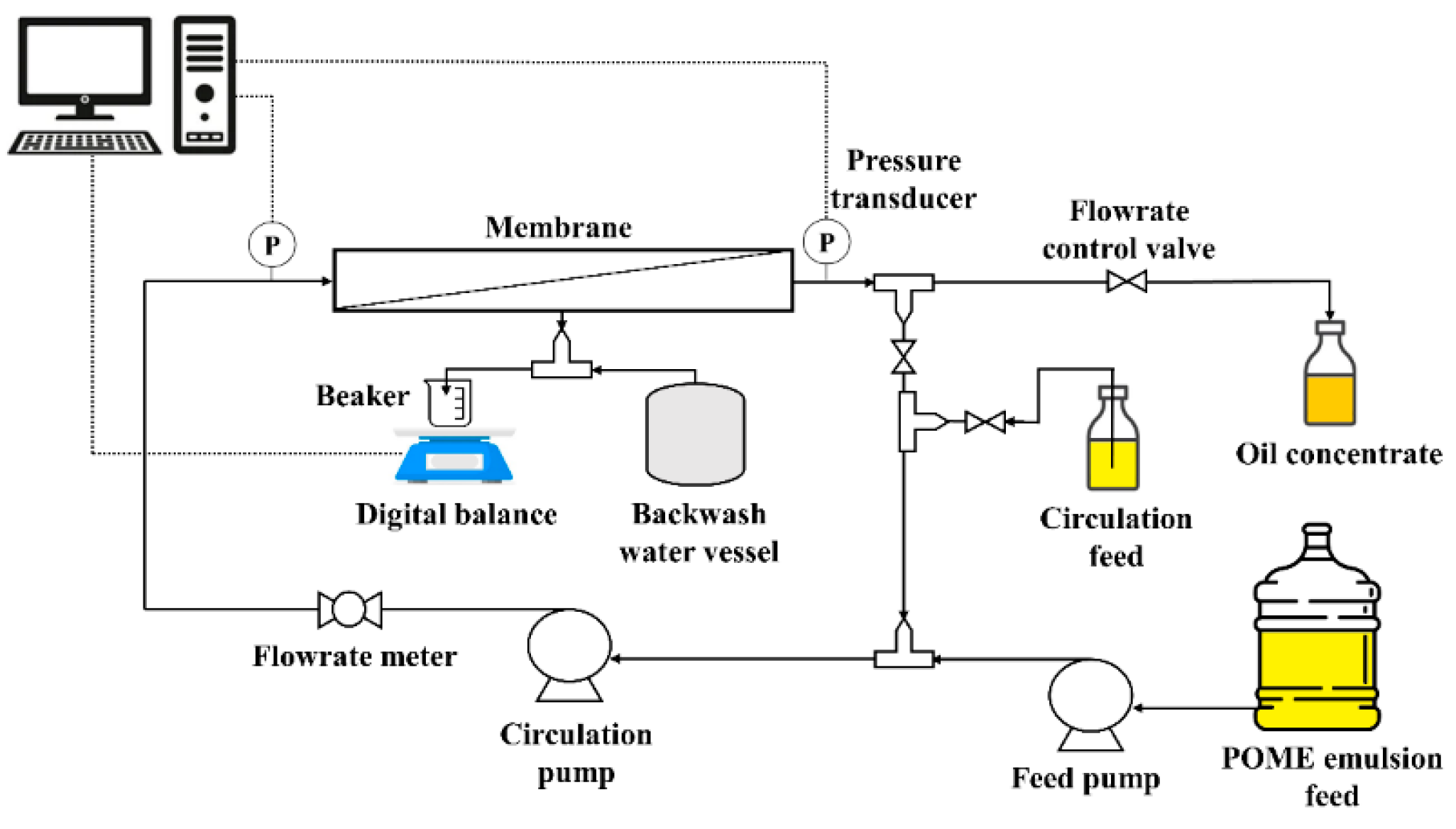
Figure 2.
Steady-state rejection capacity (Rj, % wt.) of EC, TS, turbidity, and COD at the optimum UF conditions, A) PVDF membrane at 40 LMH, and B) α-Al2O3 membrane at 60 LMH.
Figure 2.
Steady-state rejection capacity (Rj, % wt.) of EC, TS, turbidity, and COD at the optimum UF conditions, A) PVDF membrane at 40 LMH, and B) α-Al2O3 membrane at 60 LMH.
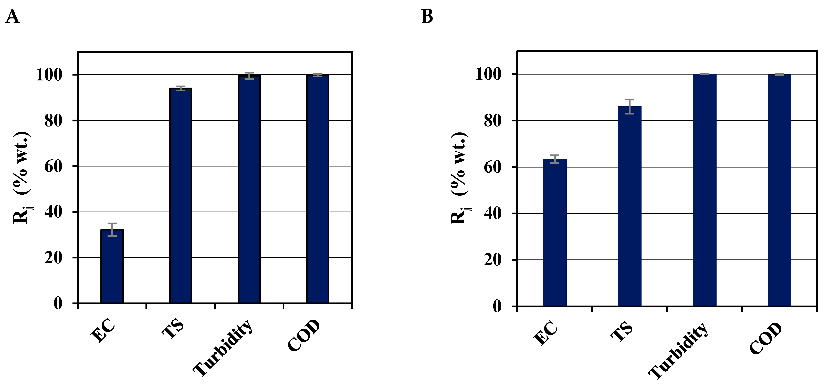
Figure 3.
Oil concentration factor (Fo), and water recovery (Rw) at CFV = 0.8 m/s. A) PVDF membrane, and B) α-Al2O3 membrane.
Figure 3.
Oil concentration factor (Fo), and water recovery (Rw) at CFV = 0.8 m/s. A) PVDF membrane, and B) α-Al2O3 membrane.
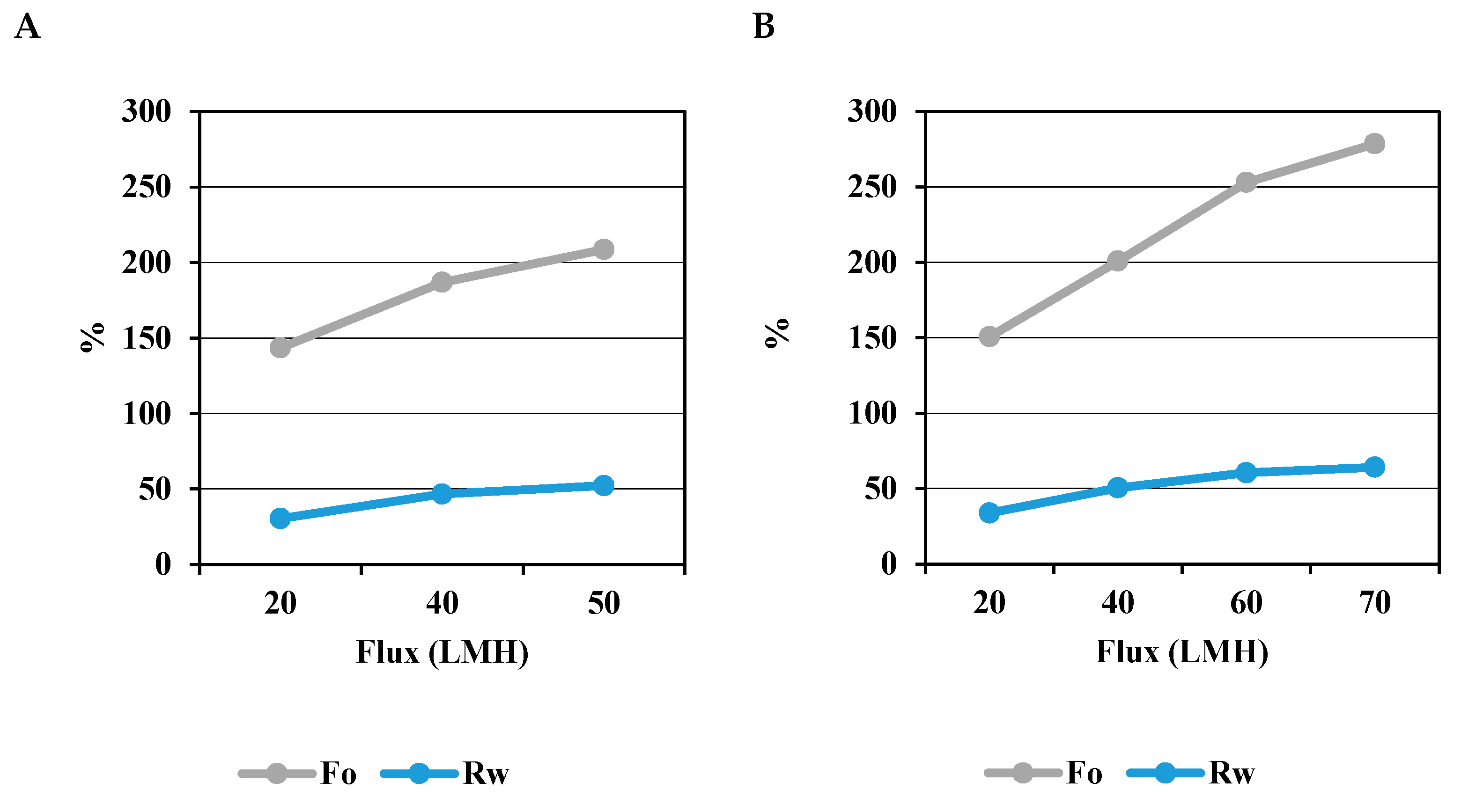
Figure 4.
TMPn evolution during constant flux of POME UF at CFV = 0.8 m/s. A) PVDF membrane, and B) α-Al2O3 membrane.
Figure 4.
TMPn evolution during constant flux of POME UF at CFV = 0.8 m/s. A) PVDF membrane, and B) α-Al2O3 membrane.
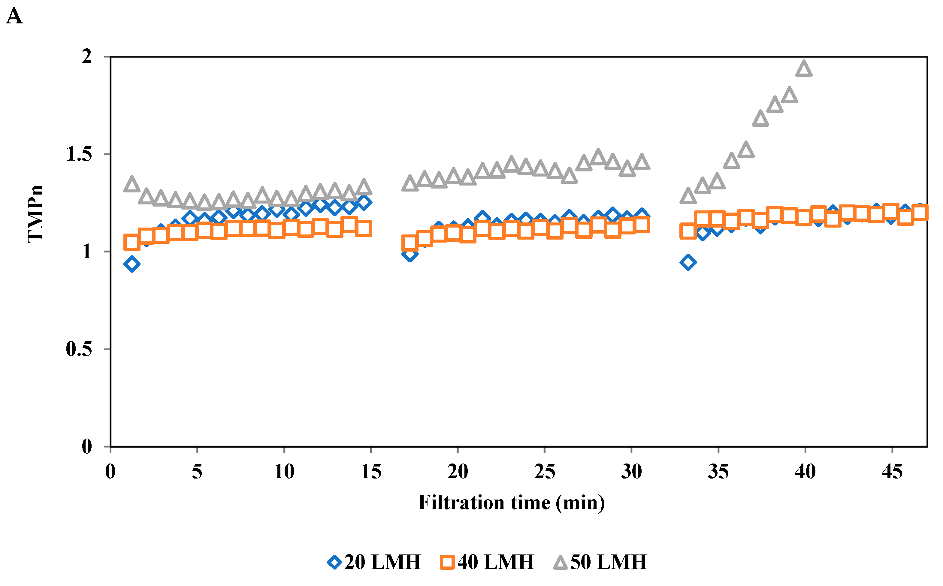
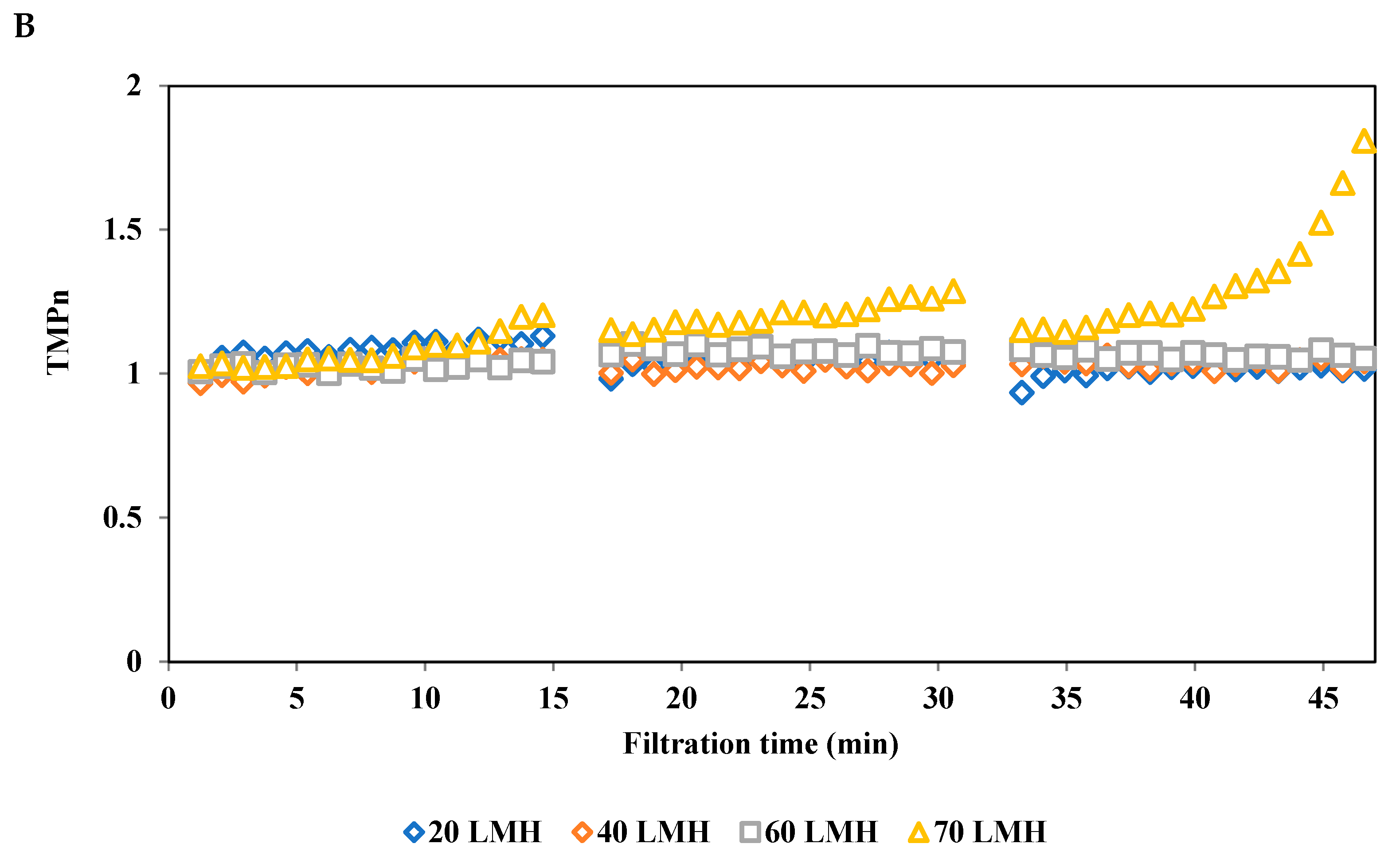
Figure 5.
Rt and Rir/Rt variation during constant flux of POME emulsion UF at CFV = 0.8 m/s. A) PVDF membrane, and B) α-Al2O3 membrane.
Figure 5.
Rt and Rir/Rt variation during constant flux of POME emulsion UF at CFV = 0.8 m/s. A) PVDF membrane, and B) α-Al2O3 membrane.
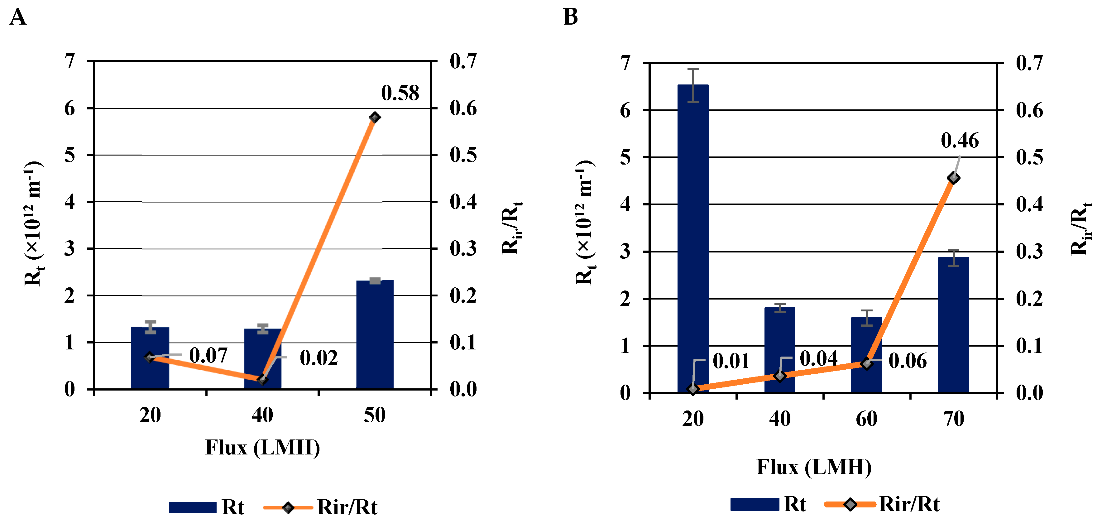
Figure 6.
Efficiency of membrane cleaning methods on the recovery of hydraulic permeability (Lh); A) PVDF membrane, B) α-Al2O3 membrane.
Figure 6.
Efficiency of membrane cleaning methods on the recovery of hydraulic permeability (Lh); A) PVDF membrane, B) α-Al2O3 membrane.
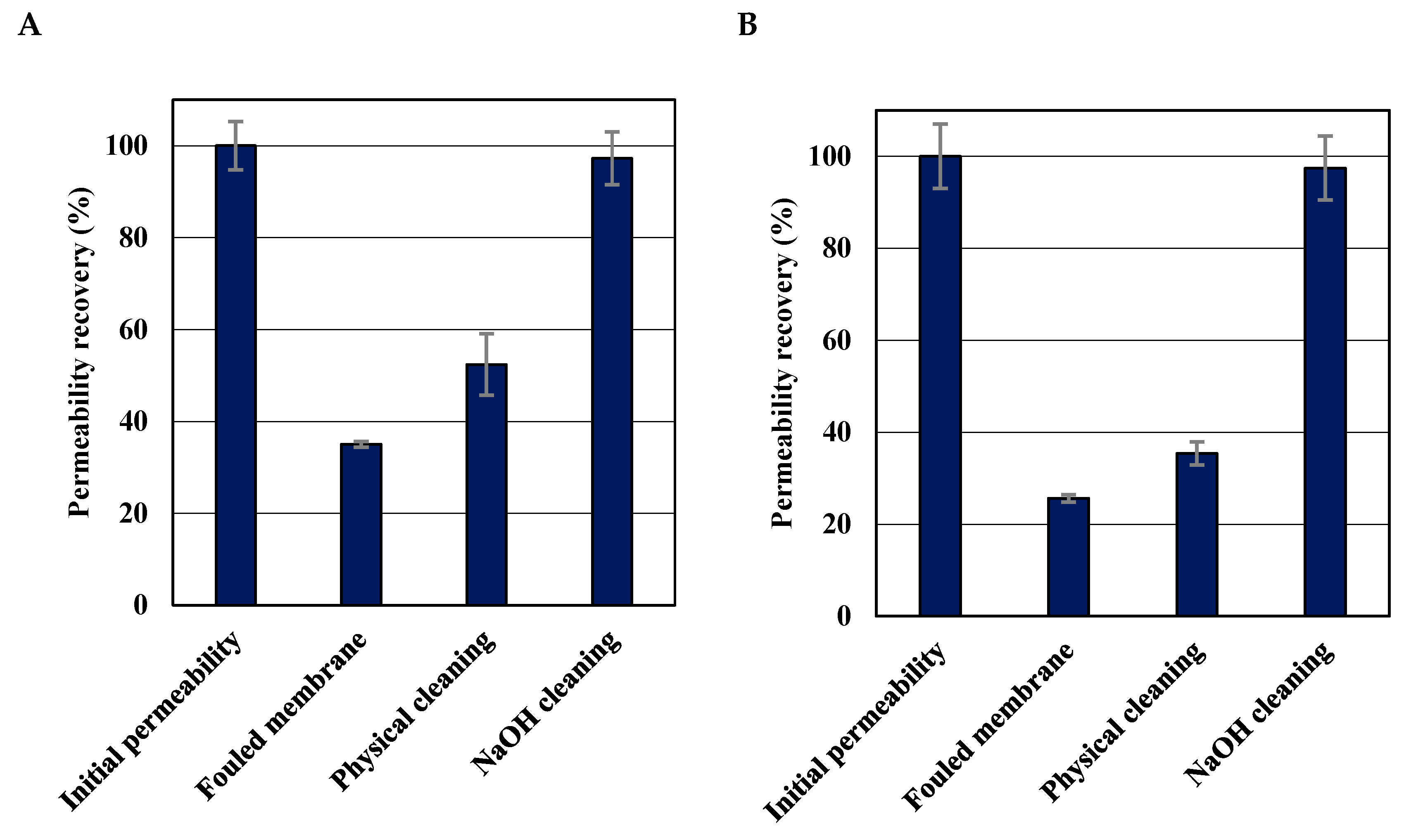
Table 1.
Properties of PVDF and α-Al2O3 membranes.
| PVDF membrane | α-Al2O3 membrane | |
| Inner diameter (mm) | 5.2 | 7.0 |
| Pore size (nm)a | 30 | 70 |
| Length (mm) | 640.0 | 600.0 |
| Cross-sectional area (m2) | 21.2×10⁻⁶ | 38.5×10⁻⁶ |
| Membrane surface area (m2) | 1.05×10⁻² | 1.3×10⁻² |
| Maximum TMPb (kPa) | 500.0 | 800.0 |
| MWCOc (kDa) | 300.0 | 500.0 |
| Operating pH range | 2-10 | 2-12 |
| Iso Electric Point | 3-4 [53] | 8.6–9.8 [54] |
| InitialPermeabilitya,d (LMH·bar) | ≥ 750 | - |
aManufacturer’s design parameters, bTrans-membrane pressure, cMolecular weight cut-off, dClean water at 25 °C.
Disclaimer/Publisher’s Note: The statements, opinions and data contained in all publications are solely those of the individual author(s) and contributor(s) and not of MDPI and/or the editor(s). MDPI and/or the editor(s) disclaim responsibility for any injury to people or property resulting from any ideas, methods, instructions or products referred to in the content. |
© 2025 by the authors. Licensee MDPI, Basel, Switzerland. This article is an open access article distributed under the terms and conditions of the Creative Commons Attribution (CC BY) license (http://creativecommons.org/licenses/by/4.0/).
Copyright: This open access article is published under a Creative Commons CC BY 4.0 license, which permit the free download, distribution, and reuse, provided that the author and preprint are cited in any reuse.


