
Submitted:
22 April 2025
Posted:
23 April 2025
You are already at the latest version
Abstract
An alternative combustion technology to replace conventional start-up and flame stabilization using fuel oil or natural gas in pulverized coal-fired boilers has been investigated. In this study, a novel plasma burner design is proposed as a replacement for traditional auxiliary burners, operating by generating plasma through the ionization of air using microwave energy. The burner features an internal combustion system and a multi-stage ignition process to enhance flame stability, improve combustion efficiency, and enable more controlled pulverized coal burning within the plasma. Supported by a magnetron generating microwave energy at 915 MHz with a 75 kW output, the burner directly ignites approximately 22% of the coal-air mixture in the plasma zone, forming a stable flame that ensures complete combustion of the remaining coal. An experimental system was established, and tests were conducted by burning up to 3000 kg/h of pulverized coal in an industrial-scale setup at Unit-1 of the 22 MWe Soma A Power Plant to optimize burner parameters. The specific microwave energy consumption was calculated as 0.055 kWh/kg of coal, demonstrating high energy efficiency and low operational cost. These results confirm that the microwave-assisted plasma burner is a technically viable, energy-efficient, and environmentally friendly alternative to conventional auxiliary burners.
Keywords:
microwave energy
; plasma combustion technology
; auxiliary burner
; multi-stage ignition
; pulverized coal combustion
; coal sampling
; flame stabilization
1. Introduction
The significant contribution of coal to power generation is attributed to its widespread availability and abundance as a solid fossil fuel in many countries. Coal as a main fuel source accounted for 35.51% of the world’s electricity generation and 36.91% of Turkey’s electricity generation in 2023 [1]. It is clear that coal is an integral part of the global energy balance and cannot be ignored, as it is not only an accessible energy source in many countries but also an indispensable one for certain industries. In other words, technological advancements concerning coal should focus on finding environmentally friendly and efficient ways to use coal. Plasma combustion technology is one such method used to ignite pulverized coal and ensure flame stabilization [2,3,4,5,6,7,8,9,10,11,12]. Through the application of this technology, it is possible to eliminate the use of fuel oil or gas during boiler start-up and to stabilize pulverized coal combustion. This technology uses plasma generated by electric arc or microwave energy to heat the air-coal mixture to a temperature where the coal’s volatiles are released and the coal ignites.
Numerous papers focusing on coal ignition and flame stabilization by plasma technology have been published worldwide [13,14,15,16,17,18,19], and this technology is widely applied in China [20]. In [13], experiments were conducted to determine the ignition and combustion conditions of high-reactivity, low-ash brown coal (ash content up to 15%) using plasma technology. The results confirmed stable ignition and combustion of pulverized coal with plasma generated by an electric arc. An industrial prototype plasma combustion system was designed and tested on a 220 t/h steam capacity boiler, successfully eliminating the need for fuel oil during cold start-up. A stable flame at 1350°C was achieved inside the boiler. In [14], the authors investigated the use of plasma technology for cold start-up in a pilot plant burning pre-dried, low-ash lignite. A swirl burner using an electric arc plasma torch with a power range of 4 to 7 kW was designed and tested for pulverized coal combustion. The study examined the effects of fuel moisture and particle size, showing that lignite with up to 20% moisture and particle size below 450 μm could be stably ignited. However, flame instability was observed with lower-quality lignite. Articles [15,16] assessed the potential for improving boiler efficiency by applying plasma combustion technologies to ignite highly reactive, low-ash coal (15%) and reduce unburned fuel. Using CFD, a model of the combustion chamber with twelve tangential burners and two plasma burners was developed. The application of plasma combustion technology led to a more uniform temperature and velocity distribution at the combustion chamber exit. The average exit temperature increased from 1220°C to 1260°C, indicating a more intense combustion of the pulverized coal. The use of plasma combustion technologies to enhance the efficiency of thermal power plant units may be economically viable, as plasma systems are considerably more cost-effective than traditional fuel oil. However, the authors emphasize the need for further research on the feasibility of plasma combustion technology before such systems can be implemented. In [17], the plasma ignition of highly reactive lignite dust particles in a flat flame burner was studied using a high-voltage DC plasma torch with a rod electrode. The calculations indicated that the coal ignition delay time decreased by 0.8-3.5 ms, depending on the ambient temperature, which ranged from 1200 K to 1800 K. The study examined the effects of both chemical and thermal factors on coal ignition, revealing that the thermal effect dominates. Experimental results showed that as the ambient temperature increased from 1200 K to 1800 K, the ignition delay time reduced from 2.9 ms to 1.2 ms, which aligns with the calculated predictions. In [18], the plasma ignition of coal using an alternating current (AC) plasma torch was tested to reduce fuel oil consumption in a pulverized coal boiler at a power plant. Experiments were conducted to evaluate the electrode service life of the AC plasma torch, with the operating life of the electrodes determined to be 530 hours. The plasma burner was specifically designed to ignite low-ash, low-quality coal through the staged combustion principle. To assess the impact on combustion characteristics such as plasma torch power, combustion temperature, and carbon burnout rate, the power was varied between 150 kW and 300 kW. At 300 kW plasma torch power, a flame temperature of 940°C and a carbon burnout rate of 52.2% were achieved with a coal torch length of 6.3 m. These results confirmed the effectiveness of igniting low-quality coal using an oil-free AC plasma torch. In [19], the FLOREAN program for CFD modeling was used to compare two combustion modes in a pulverized coal boiler with a steam capacity of 160 t/h: conventional combustion of low-quality coal (30% ash content) using 8 tangential burners arranged in two levels, and combustion with plasma fuel systems installed in two opposite burners on the lower level. The calculations provided temperature, velocity, and concentration fields for carbon oxides (CO) and nitrogen oxides (NO) in the boiler furnace. The study demonstrated that plasma combustion systems can effectively reduce harmful CO and NO emissions when burning low-quality coal. It is important to note that plasma combustion technology is primarily studied through numerical-theoretical methods and laboratory-scale experimental research.
Plasma combustion technology has been widely adopted in thermal power plants by the Chinese company LY Power, which, by 2020, had implemented this technology in 862 power units, including 31 units across South Korea, Russia, Southeast Asia, Europe, and Africa [20]. These units have a total installed capacity exceeding 370 GW. LY Power also developed the world’s first oil-free thermal power plant using plasma combustion technology. This system eliminates the need for fuel oil in both boiler start-up and the stabilization of the pulverized coal flame. However, a limitation of LY Power’s plasma combustion technology is that the ash content of the coal being burned must not exceed 30%.
The reviewed articles indicate that, in laboratory, pilot, and industrial-scale applications, plasma was produced through electric arcs generated by AC (alternating current) or DC (direct current) technologies. However, a common limitation noted for both methods is the relatively short service life of the electrodes.
In this regard, a novel burner design employing plasma combustion technology, based on the ionization of air using microwave energy to produce plasma, is proposed in this study as a replacement for traditional auxiliary burners. The proposed burner features an internal combustion system and multi-stage ignition process to enhance flame stability, improve combustion efficiency, and enable more controlled coal burning within the plasma. To determine the optimal operating parameters of the novel auxiliary burner, a test setup was established in Unit-1 22 MWe of the Soma A Thermal Power Plant, and integrated into a newly designed pulverized coal storage system. In this setup, the coal used in the original boiler design was utilized instead of traditional fuels like fuel oil or gas for initial ignition and flame stabilization in thermal power plant boilers.
Overall, these findings demonstrate that the proposed auxiliary burner design has the potential to be a more environmentally friendly and efficient alternative to conventional burners in the start-up process of pulverized coal-fired boilers and in ensuring flame stabilization.
2. Microwave-Assisted Plasma Combustion Technology
2.1. Microwave-Assisted Burner Structure
The proposed microwave-assisted industrial-scale burner is an internal combustion, multi-stage ignition system for pulverized coal, in which a small portion of pulverized coal is combusted to serve as an ignition source for igniting a larger quantity of pulverized coal, thereby facilitating the formation of a stable and sustained flame required for efficient pulverized coal combustion. As shown in Figure 1, the three-stage ignition system generates plasma (1) in the first stage by ionizing air, used as the working gas, through microwave energy. The secondary air, supplied through a 150 mm diameter pipe connected to the waveguide (11), is regulated by an electronically controlled fan to adjust its flow rate. This air is directed toward the burner and delivered into the inner section of the coaxial line (2). The secondary air serves two primary functions: first, it facilitates the formation of a stable plasma flame; second, it prevents the high temperatures of the plasma flame from reaching the waveguide and the magnetron, thereby protecting the magnetron from potential thermal damage.
Inside the coaxial line, a tungsten rod with a diameter of 5 cm is positioned (3). A second metal rod with a copper tip, housed within the igniter (6), is pneumatically actuated to move in and out through an opening at the top of the burner. When this rod strikes the tungsten rod, a spark is produced, initiating plasma formation. The position of the copper-tipped rod along the axis of the coaxial line is adjusted to optimize the conditions for stable plasma generation.
A fan pressurizes the pulverized coal and primary air mixture, which is then supplied to the burner through a 300 mm diameter pipe. A damper (8), capable of adjusting to various angles on this pipe, divides the coal-air (black lined in Figure 1) mixture into two streams: one portion is directed to channel (4) to be ignited by the plasma flame, while the remaining portion is directed to channel (5). Upon entering channel (4), the coal-air mixture interacts with the plasma flame, initiating combustion and causing the flame to elongate. Subsequently, as the coal-air mixture introduced through channel (5) ignites within this extended flame (red lined in Figure 1), the overall flame propagates outward from the burner.
A camera and a pyrometer (7), installed in the burner’s port, provide real-time visual monitoring of the processes inside the burner and precise temperature measurements of the pulverized coal-plasma flame. The flow rates and temperatures of both the pulverized coal-primary air mixture and the secondary air are measured through measurement ports (9) and thermocouples (10), respectively, mounted on the pipe. In addition, coal samples taken from the measurement ports (9) can be used to determine the amount of coal combusted inside the burner.
2.2. Industrial Experimental Setup
The prototype burner, designed for this study, has been integrated with a microwave power generator (magnetron) and its auxiliary systems, as presented in Figure 2. The microwave energy generated by the magnetron at 915 MHz with an output power of 75 kW is transmitted to the burner through a series of rectangular waveguides, following its passage through a circulator and a three-stub tuner. Near the open end of a coaxial line located at the top of the burner, this microwave energy ionizes the air to generate plasma. The rectangular waveguide used is of type WR 975, with dimensions of 247.65 mm in width and 123.825 mm in height. A circulator is a device designed to control the direction of signal flow, ensuring that microwave energy propagates in the intended direction while preventing any reverse transmission. The three-stub tuner is installed between the burner and the circulator. To achieve maximum absorption of the supplied microwave power, the stubs of the tuner must be properly adjusted to minimize reflected power. Otherwise, a portion of the microwave energy will be reflected rather than fully absorbed by the plasma and will subsequently be dissipated in the water load connected to the circulator.
The cooling system includes four pumps operating at 6 bar pressure and 0.75 kW power. The water circulated by these pumps maintains the temperature of the magnetron, circulator, and power supply within the system, preventing overheating. The control system monitors and regulates the operating parameters of the magnetron, power supply, and cooling system to ensure stable plasma generation. The power supply cabinet provides electrical power to system components, primarily the magnetron. Protects the system equipment from electrical faults by disconnecting the power in case of an overload or short circuit.
In the subsequent phase of the study, a newly designed pulverized coal storage system was integrated with the burner, comprising a coal bunker, a fan, and a pipe for transferring the coal-air mixture. The industrial-scale experimental setup incorporating this system is shown in Figure 3. The pulverized coal, transferred to the ejector with the help of a rotary feeder located below the bunker, is injected into the primary air stream at the fan outlet. This pulverized coal-air mixture is conveyed through a 300 mm diameter pipe to the burner. The feed rate of coal can reach up to a value of 3000 kg/h, which is the maximum output capacity of the electronically controlled rotary feeder. The flow rates of primary and secondary air can also be adjusted with the electronic control system connected to the fan. While the flow rate of primary air can reach up to a maximum of 1000 Nm3/h, the flow rate of secondary air can reach a maximum of 6000 Nm3/h.
3. Materials and Methods
The first step in determining the optimal operating parameters of the burner begins with separately measuring the velocities of the secondary air, primary air, and the mixture of primary air and pulverized coal within the pipe. Next, the primary air and pulverized coal mixture sample is taken from the pipe according to the ASME PTC 4.2 Coal Sampling Standard. Pulverized coal samples taken from the pipe are prepared under laboratory conditions for analysis according to the ASTM D 2013 coal sample preparation standard. The proximate analyses of the pulverized coals prepared for analysis, including moisture (ASTM D 3173), ash (ASTM D 3174), volatile matter (ASTM D 3175), and gross calorific value (ASTM D 5865), were performed according to the analysis methods specified in the standards. Additionally, a sieve analysis is subjected to determine the particle size distribution of the pulverized coal. The optimal operating parameters of the burner are determined based on the evaluation of the data obtained from the analyses.
The velocity of the pulverized coal and primary air mixture is measured at the measurement port, indicated as number 9 in Figure 1, which is mounted at the burner inlet. Figure 4 shows the pipe cross-section, differential, and static pressure measurement equipment.
The differential pressure probe shown in Figure 4(a) is inserted into the pipe through the measurement port, perpendicular to the flow of the pulverized coal-air mixture according to the ASME PTC 4.2 standard, as shown in Figure 4(b), the interior of the circle is divided into circles with equal areas on the axial axis. The differential pressure values measured by the probe at the points where the outer circumference of these equal-area circles intersect the radial axis of the pipe are recorded.
After the measurement, the average of the differential pressure values measured along the radial axis is taken. The static pressure and temperature values inside the pipe are measured using the static pressure probe shown in Figure 4(c). The probe is inserted into the pipe through the measurement port perpendicular to the flow of the pulverized coal-air mixture and pushed to the center of the pipe. The static pressure and temperature values are recorded from the manometer connected to the probe. The air density inside the pipe is calculated by applying the measured static pressure and temperature values to the ideal gas Equation (1). The air velocity inside the pipe is determined by applying the air density, the average differential pressure value, and the probe’s k correction factor to the Bernoulli Equation in (2). The airflow rate is obtained by multiplying the air velocity inside the pipe by the pipe’s cross-sectional area.
where,
P: Static Pressure (Pa),
R: Universal gas constant (R = 287 J/kgK),
T: Fluid Temperature (K),
ρ: Fluid Density (kg/m3).
The simplest form of the Bernoulli Equation (2) is:
In the Bernoulli Equation (2), when the initial velocity is zero and the differential pressure measurement probe moves along the x-axis, the fluid’s velocity at the second point is calculated according to Equation (3): (h1, h2 = 0, V1 = 0).
where,
V2: Fluid velocity (m/s),
k: Probe coefficient (k = 0,92),
ΔP: The average differential pressure values measured at the measurement port (Pa),
ρ: Fluid Density (kg/m3)
In determining the burner’s operating parameters, it is crucial to focus on employing an accurate and standardized coal pipe sampling method. According to the ASME PTC 4.2 Coal Sampling Standard, isokinetic sampling ensures that the pulverized coal enters the sample container through the opening at the tip of the coal sampling probe in Figure 5(a) and is collected at the same velocity as the coal air mixture passing through the pipe, which best represents the sampling conditions. The isokinetic coal sampling test begins with marking off the pulverized coal lines to be sampled for an equal area traverse. Figure 5(b) illustrates coal sampling at 48 points along the axial axis of the coal pipe, which has been divided into equal areas.
To extract the coal from inside the pipe isokinetically, the suction velocity at the probe tip must equal the velocity of the coal-air mixture within the pipe. In Figure 5, measurements are taken at 12 different points at each measurement port. The ejector suction pressure is calculated separately for each measurement port using Equation (4).
where,
SPE: Section Pressure of the ejector (Pa),
N: The number of points at each measurement port,
k: Probe coefficient (k=0,92),
The differential pressure value at each measurement point (Pa).
To keep the speed at the end of the coal sampling probe constant, the ejector differential pressure must be maintained at a constant value. To achieve this, there is an adjustable ball valve before the ejector. When this valve is continuously adjusted, the speed at the end of the coal sampling probe is kept constant. The area of the opening at the end of the coal sampling probe is 1.95 x 10⁻⁴ m². Pulverized coal particles collected isokinetically from the pipe enter the cyclone and then accumulate in the collection chamber beneath the cyclone. The total coal flow rate in the measurement pipe is calculated using Equation (5).
where,
TCF: Total Coal Flow (kg/h),
TSW: Total Sample Weight (g),
CAP: Cross-sectional area of the pipe (m2),
CASP: Cross-sectional area of the coal sampling probe (m2),
TNP: Total number of ports used in the measurement,
NSP: Number of sampling points at each port,
t: Sampling time at each point (s).
According to this standard, ports placed on the pipe should be positioned at a distance away from elbows or points where the flow direction changes. The coal-air mixture is typically not homogeneous in pulverized coal power plants. The coal-air mixture can flow in a roping form, causing the mixture to concentrate in certain areas of the pipe, affecting sampling efficiency. In this case, sampling from additional ports can minimize measurement errors. According to this standard, the measurement error for static pressure is ± 5 mm WC, the measurement error for coal sampling is ± 5%, the measurement error for coal flow is ± 10%, the measurement error for airflow is ± 5%, and the measurement error for temperature is ± 2 °C.
4. Results and Discussion
The experiments were conducted as follows: Secondary air, which can be gradually increased to 1000 Nm³/h using an electronically controlled fan, was delivered into the burner. During the measurements, the temperature of the secondary air drawn from the atmosphere, which was used as the working gas, was 30°C. As shown in Figure 1, the pipe diameter through which the secondary air enters is 150 mm. The secondary air velocities, which were gradually increased, were measured at the same port on the pipe. After repeated measurements, the secondary air flow rates obtained from 8 separate measurements are shown in Table 1.
To form the plasma flame, the secondary air was directed into the burner through a 150 mm diameter pipe using an automatically controlled fan. Then, the magnetron power was set to 18.75 kW, which is 25% of its total power of 75 kW, and maintained at this level, with the frequency set to 915 MHz. A spark is created when a metal rod with a copper tip, moved by a double-acting pneumatic valve operated with compressed air, strikes the metal rod made of tungsten in the center of the coaxial line. Microwave energy transforms the secondary air, serving as the working gas, into plasma near the open end of the coaxial line through the spark generated. After the formation of plasma, the magnetron power is increased to 37.5 kW, which is 50% of the total power. The ignition process was then repeated with a gradual increase in the airflow rate. When the secondary air flow rate reached 250 Nm³/h, the first plasma flame was obtained. About 3 minutes after the initial plasma formation was observed, an overcurrent fault signal appeared on the control system, causing the magnetron to deactivate. When the air flow rate was increased to 350 and 450 Nm³/h, the control system detected an overcurrent fault, similar to what occurred at an airflow rate of 250 Nm³/h, resulting in the automatic shutdown of the magnetron in both attempts. When the air flow rate is increased to 500 Nm³/h and ignition is performed, plasma forms, and no overcurrent fault signal is observed during ignitions at various air supply rates ranging from 500 Nm³/h to 1000 Nm³/h.
During the ignition tests, the 3-stub tuner was adjusted each time to minimize the reflected power. The evaluation of the results determined that the airflow rate of the secondary air directed to the burner as a working gas should be at least 500 Nm³/h.
A high-resolution camera was temporarily mounted 1 meter away from the burner outlet, as shown in Figure 6(a), to observe the transformation of secondary air entering the burner through direct flow into plasma. When the air flow rate is increased to 500 Nm³/h and ignition is performed, plasma forms as shown in Figure 6(b).
The temperature of the plasma flame formed at different air flow rates via an electronically controlled fan is measured using a thermocouple mounted at the burner outlet. Initially, the secondary air flow rate is set to 500 Nm³/h, and plasma is generated through the ignition process. Subsequently, the magnetron output power is adjusted to 50%, 75%, and 100% of the total power, and the corresponding temperature values recorded by the thermocouple at the burner outlet are documented. The secondary air flow rate of 500 Nm³/h, measured in the M4 measurement as presented in Table 1, reaches a maximum temperature of 474 °C at 100% magnetron output power. Moreover, when different magnetron output powers are applied to the air flow rates corresponding to M5, M6, M7, and M8 measurements, the temperature values recorded at the burner outlet are illustrated in the graph shown in Figure 7.
As shown in Figure 1, which illustrates the burner structure, the damper labeled as number 9 on the pipe where primary air enters the burner is adjusted to direct a portion of the mixture to channel 4, while the remaining part is directed to channel 5. The damper is adjustable between 0 and 180 degrees. During the tests, the damper was gradually rotated counterclockwise to perform the experiments. The fan was activated, which will deliver the primary air to the burner through a 300 mm diameter pipe. At the time the tests were conducted, the ambient temperature of the air was 33°C. Although the fan has automatic control, it was set to operate with a maximum capacity of 6000 m³/h airflow. After the damper was set to 25°, measurements were taken at the port on the pipe leading to the burner and separately at the ports in channels 4 and 5. In this way, the data obtained from each port was thoroughly examined and compared. These measurements were conducted to understand how the damper position influences and affects the primary airflow.
The M9 measurement in Table 2 was conducted at the port on the 300 mm diameter pipe at the burner inlet. The M410 and M511 measurements are taken on channels 4 and 5. Both channels have a diameter of 150 mm. After the damper was set to 50°, measurements were taken at the ports in channels 4 and 5. Finally, the damper was adjusted to 75°, and measurements taken at the same ports are shown in Table 2, along with the previous measurements.
After the measurements were completed, the secondary air flow rate was adjusted to 500 Nm³/h, and the ignition process was carried out. Once the plasma flame was established, the damper at the burner inlet was adjusted to 25°, and then to 50° and 75°, with primary air being introduced into the burner. It was observed that the plasma flame remained stable at 25° but extinguished when the damper was set to 50° and 75°. Consequently, the damper was set back to 25°, and tests were conducted with pulverized coal and primary air mixtures.
In Figure 3, the rotary feeder mounted at the bottom outlet of the pulverized coal storage bunker consists of an 8-compartment wheel and can operate at a speed of 16 revolutions per minute. After disconnecting the rotary feeder from the pipe through which it transfers pulverized coal, it was operated for one minute, and the amount of pulverized coal collected in a container was weighed. Each compartment of the wheel was calculated to transfer 390 g of coal. In this case, the rotary feeder can extract 16 x 8 x 390 g = 49,920 g, approximately 50 kg, in one minute and transfer approximately 3000 kg of coal per hour from the bunker to the pipe.
The M16 measurement, as detailed in Table 3, was obtained from four distinct ports positioned at 45-degree intervals along the radial axis of the pipe at the burner inlet, as illustrated in Figure 5(b). Twelve individual measurements were recorded for each port, and their averages were computed. Subsequently, the average values derived from each of the four ports were aggregated to provide a final mean value, presented in Table 3. Upon examining the data presented in Table 3, with a primary air flow rate of 5803 Nm³/h, 2941 kg/h of pulverized coal can be transported through a 300 mm diameter pipe at a velocity of 22.81 m/s. It has been concluded that 1 kg of pulverized coal can be transported with 2 Nm³ of primary air. According to the M417 measurement taken at the measurement port mounted on channel 4, the velocity of the primary air and pulverized coal mixture has been determined to be 18.23 m/s. Measurements were conducted at three ports mounted at 60-degree intervals along the radial axis of channel 4. The average of six measurements taken at each port was calculated. The averages from these three ports were then further averaged, and the results are presented in Table 3. Following the stabilization of the damper opening at 25 degrees, the M16 measurement determined that out of the total 2941 kg/h of pulverized coal, 652 kg/h passed through channel 4. In conclusion, 22% of the pulverized coal transported by the primary air (652 kg/h out of 2941 kg/h) passes through channel 4 and interacts with the plasma flame for combustion. The same measurements conducted on channel 4 were also performed on channel 5. The values obtained from measurement 18 (M518) on channel 5 are presented in Table 3. The velocity of the primary air and coal mixture was measured at 77.31 m/s. A total of 78% of the coal (2261 kg/h out of 2941 kg/h) is transported by the primary air and passes through channel 5. The primary air and coal mixture entering channel 5 of the burner is subsequently ignited by the flame produced from the plasma interaction with the coal entering channel 4. As the coal feed rate to the burner reaches 3000 kg/h, the magnetron consumes 37,5 kWh of energy. The specific microwave consumption per kilogram of coal is calculated as Q = 37,5 kWh / (2941 kg/h x 0.22) = 0.058 kWh/kg.
In the experiments, lignites obtained from the Soma coal basin, which have high moisture and ash content, were used. The proximate analyses of the coals, including moisture, ash, volatile matter, and gross calorific value, were conducted according to the analysis methods specified in the standards, and the results are presented in Table 4.
Table 4 presents the analysis results of the coal sample taken from the pipe during the M16 measurement. Upon examining the ’As received basis’ values in Table 4, it is observed that the coal represents the characteristics of coal produced in the Soma coal basin.
In the M16 measurement, the pulverized coal sample taken from the pipe was sieved using screens determined according to the Tyler sieve series. The weight percentages and the cumulative undersize and oversize values of the pulverized coal for each sieve fraction are presented in Table 5.
The curve shown in Figure 8 was plotted using the cumulative undersize distribution (%) values and particle size data from Table 5.
When the curve in Figure 8 is examined, it is observed that the amount of pulverized coal with a particle size below 90 µm is 61.14%. According to the boiler design specifications of Soma A Power Plant, 55% of the pulverized coal exiting the pulverizer is required to have a particle size smaller than 90 µm. As part of this study, the renewal of the pulverizer rotors and the replacement of the internal liners have led to a slight improvement in grinding efficiency.
The coal-air mixture, entering the burner at a speed of 20-22 m/s, is directed into two separate channels by a damper that can be adjusted to different angles. The burner’s internal structure is designed to support a three-stage coal ignition process. In the first stage, a portion of the total coal and airflow is ignited by plasma. The air-coal mixture supplied to the second and third stages of the burner is subsequently ignited by the stable flame generated through plasma-assisted ignition in the initial stage. Tests conducted at different damper angles revealed that the most efficient combustion occurs when the damper is set to 25°. In this case, 22% of the coal-air mixture is burned in the plasma flame, while the remaining 78% is ignited within the flame generated by the coal burned in the plasma flame, causing the flame to extend outward from the burner. When the amount of coal fed to the burner reaches 3000 kg/h, 650 kg/h of coal (3000 kg/h x 0.22) is carried with the air and burned within the plasma flame. As the coal feed rate to the burner reaches 3000 kg/h, the magnetron consumes 37,5 kWh of energy. The specific microwave consumption per kilogram of coal is calculated as Q = 37,5 kWh / (3000 kg/h x 0.22) = 0.055 kWh/kg.
The flame resulting from the interaction of coal with plasma shows a cylindrical form extending along the burner axis. Typically, at a distance of about 15 cm from the end of the coaxial line, there is a bright luminous formation—the plasma flame—with a diameter of approximately 20-25 cm, resulting from the microwave energy converting the air into plasma.
Primary and secondary air flow rates control the plasma flame position. After the plasma flame interacts with the coal, a temperature value of 1200 to 1350 °C is measured. As the coal feed rate increases, the length of the flame gradually increases. When the coal feed rate reaches approximately 3000 kg/h, the flame length can extend up to 4 meters. Figure 9 shows a photograph of the flame extending from the burner.
The results obtained show that, compared to conventional burners, in a microwave burner, the coal powder and air mixture ignites early and reliably within the plasma flame even at quite low temperatures, around 30°C, and a stable flame is formed.
The process of igniting and burning pulverized coal within the plasma created by microwaves is similar to the process in the plasma formed by direct current and alternating current electric arcs. First, when coal particles are exposed to the high temperature of the plasma flame, they disintegrate into very small pieces due to thermal shock. This leads to a significant increase in the total surface area of the coal particles and results in the release of a greater amount of volatile matter. Secondly, the electrons and ions present in the plasma environment intensify the chemical reactions of coal oxidation. In the case of microwave plasma, these processes are enhanced due to the plasma being highly unstable and the electron temperature being as high as 11600 K [21].
Experiments have shown that the coal-air mixture fed into the burner can easily ignite within the plasma formed by converting secondary air into plasma with microwave energy. In this case, a stable flame of plasma and burning coal particles emerges almost instantaneously.
5. Conclusions
In this study, a novel microwave-assisted burner design based on plasma combustion technology was developed and tested for pulverized coal combustion applications. The experimental results obtained from the industrial-scale prototype demonstrated that plasma generated through microwave energy can effectively and reliably ignite pulverized coal, ensuring stable flame formation even at low ambient temperatures.
The multi-stage internal combustion system of the burner allowed for controlled ignition and combustion of pulverized coal, achieving high flame stability and combustion efficiency. The experimental setup, integrated into the Soma A Thermal Power Plant’s Unit-1, confirmed that at a secondary air flow rate of 500 Nm³/h and with a magnetron operating at 37.5 kW (50% of total capacity), a stable plasma flame was established. Furthermore, the system successfully ignited coal feed rates up to 3000 kg/h, where approximately 22% of the total coal was combusted directly within the plasma zone, initiating a stable and extended flame.
The experimental data indicated that the plasma-assisted burner enabled efficient ignition of low-quality lignite coal with high ash and moisture content, commonly found in the Soma basin. The particle size distribution analysis confirmed that 61.14% of the pulverized coal was below 90 µm, exceeding the plant’s design specifications, which further facilitated the combustion process within the plasma flame. Additionally, the flame temperature was measured to range between 1200°C and 1350°C, demonstrating the burner’s capability to create optimal combustion conditions without the need for conventional fossil fuels such as fuel oil or natural gas during start-up and flame stabilization.
The specific microwave energy consumption was calculated to be approximately 0.055 kWh/kg of coal, highlighting the system’s energy efficiency. Importantly, this technology offers significant environmental and economic advantages by reducing auxiliary fuel consumption and associated emissions in coal-fired power plants.
In conclusion, the proposed microwave-assisted plasma burner represents a promising alternative to conventional auxiliary burners, combining high efficiency, operational safety, and environmental sustainability. Future research will focus on long-term operational stability, scalability for larger units, and further optimization of microwave-plasma-coal interactions to enhance performance under varying coal qualities.
Author Contributions
Conceptualization, U.T.; methodology, U.T.; software, U.T.; validation, U.T.; formal analysis, U.T.; investigation, U.T.; resources, U.T.; data curation, U.T.; writing—original draft preparation, U.T.; writing—review and editing, U.T.; visualization, U.T.; project administration, U.T. The author has read and agreed to the published version of the manuscript.
Funding
This research has been supported by EÜAŞ (Electricity Generation Company) and TKI (Turkish Coal Enterprises) and has been financed under the contract signed between these two institutions on June 4, 2016.
Data Availability Statement
The original contributions presented in this study are included in the article. For further information, the author may be contacted.
Acknowledgments
The author would like to thank the staff of the Soma A Thermal Power Plant for their technical support provided within the scope of this project.
Conflicts of Interest
The author declares that there are no conflicts of interest.
Abbreviations
| WR | Waveguide Rectangular |
| ASME | American Society of Mechanical Engineers |
| mm WC | Millimeters of water column |
| Nm3 | Normal cubic meter |
| kWh | Kilowatt-hour |
| M1 | Represents measurement number 1 |
| M410 | Represents measurement number 10 conducted on channel 4 |
| M511 | Represents measurement number 11 conducted on channel 5 |
| µm | Micrometer |
| oC | Celsius |
| K | Kelvin |
References
- Share of electricity production from coal. Available online: https://ourworldindata.org/grapher/share-electricity-coal?tab=chart (accessed on 22 June 2024).
- Messerle, V.; Karpenko, E.; Ustimenko, A. Plasma assisted power coal combustion in the furnace of utility boiler: Numerical modeling and full-scale test. Fuel 2014, 126, 294-300. [CrossRef]
- Messerle, V.; Karpenko, E.; Ustimenko, A.; Lavrichshev, O. Plasma preparation of coal to combustion in power boilers. Fuel Processing Technology 2013, 107, 93-98. [CrossRef]
- Gorokhovski, M.A.; Jankoski, Z.; Lockwood, F.C.; Karpenko, E.I.; Messerle, V.E.; Ustimenko, A.B. Enhancement of pulverized coal combustion by plasma technology. Combustion Science and Technology 2007, 179, 2065-2090. [CrossRef]
- Messerle, V.; Ustimenko, A.; Tastanbekov, A. Plasma ignition of solid fuels at thermal power plants. Part 1. Mathematical modeling of plasma-fuel system. Thermophysics and Aeromechanics 2022, 29, 295-310. [CrossRef]
- Kanilo, P.; Kazantsev, V.; Rasyuk, N.; Schünemann, K.; Vavriv, D. Microwave plasma combustion of coal. Fuel 2003, 82, 187-193. [CrossRef]
- Messerle, V.E.; Ustimenko, A.B. Modeling of Coal Ignition in Plasma-Fuel Systems With an Electric Arc Torch. IEEE transactions on plasma science 2019, 48, 343-349. [CrossRef]
- Gorokhovski, M.; Karpenko, E.; Lockwood, F.; Messerle, V.; Trusov, B.; Ustimenko, A. Plasma technologies for solid fuels: experiment and theory. Journal of the Energy Institute 2005, 78, 157-171. [CrossRef]
- Messerle, V.; Ustimenko, A. Modelling of the pulverized coal plasma preparation for combustion. Physical Sciences and Technology 2021, 8, 14-25. [CrossRef]
- Glushkov, D.O.; Kuznetsov, G.V.; Chebochakova, D.A.; Lyakhovskaya, O.E.; Shlegel, N.E.; Anufriev, I.S.; Shadrin, E.Y. Experimental study of coal dust ignition characteristics at oil-free start-up of coal-fired boilers. Applied Thermal Engineering 2018, 142, 371-379. [CrossRef]
- Glushkov, D.; Matiushenko, A.; Nurpeiis, A.; Zhuikov, A. An experimental investigation into the fuel oil-free start-up of a coal-fired boiler by the main solid fossil fuel with additives of brown coal, biomass and charcoal for ignition enhancement. Fuel Processing Technology 2021, 223, 106986. [CrossRef]
- Messerle, V.E.; Ustimenko, A.B. Thermodynamic and kinetic modeling and experiment on plasma ignition of pulverized high-ash coal. Applications in Energy and Combustion Science 2024, 17, 100248. [CrossRef]
- Butakov, E.; Burdukov, A.; Alekseenko, S.; Yaganov, E. Plasma Ignition System to Start Up Pulverized Coal Boilers: Experimental Simulation and Full-Scale Test. Journal of Engineering Thermophysics 2022, 31, 375-383. [CrossRef]
- Youssefi, R.; Maier, J.; Scheffknecht, G. Pilot-scale experiences on a plasma ignition system for pulverized fuels. Energies 2021, 14, 4726. [CrossRef]
- Pawlak-Kruczek, H.; Mularski, J.; Ostrycharczyk, M.; Czerep, M.; Baranowski, M.; Mączka, T.; Sadowski, K.; Hulisz, P. Application of plasma burners for char combustion in a pulverized coal-fired (PC) boiler–Experimental and numerical analysis. Energy 2023, 279, 128115. [CrossRef]
- Mączka, T.; Pawlak-Kruczek, H.; Niedzwiecki, L.; Ziaja, E.; Chorążyczewski, A. Plasma Assisted Combustion as a Cost-Effective Way for Balancing of Intermittent Sources: Techno-Economic Assessment for 200 MWel Power Unit. Energies 2020, 13, 5056. [CrossRef]
- Zhao, F.; Li, S.; Ren, Y.; Yao, Q.; Yuan, Y. Investigation of mechanisms in plasma-assisted ignition of dispersed coal particle streams. Fuel 2016, 186, 518-524. [CrossRef]
- Yan, G. Ignition characteristics of lean coal used a novel alternating-current plasma arc approach. Journal of Thermal Science 2022, 31, 571-581. [CrossRef]
- Bolegenova, S.; Askarova, А.; Georgiev, A.; Nugymanova, A.; Maximov, V.; Bolegenova, S.; Mamedov, B. The use of plasma technologies to optimize fuel combustion processes and reduce emissions of harmful substances. Energy 2023, 277, 127635. [CrossRef]
- Plasma Ignition and Combustion Stabilization (PICS) Technology for Pulverized Coal Fired Boilers. Yantai Longyuan Power Technology Co., Ltd. (LY Power). Available online: https://en.lypower.com/plasma-ignition-and-combustion-stabilization-picstechnology-for-pulverized-coal-fired-boilers-product/. (accessed on 29 December 2023).
- Motornenko, A.P.; Schünemann, K. Plasmatron with microwave excitation of nonequilibrium plasma. AEU-International Journal of Electronics and Communications 2001, 55, 337-341.
Figure 1.
1—Plasma Flame, 2—Coaxial Line, 3—Tungsten Metal Rod, 4 and 5—Channel, 6—Igniter, 7—Camera and Pyrometer, 8—Damper, 9—Measurement Port, 10—Thermocouple, 11—Waveguide.
Figure 1.
1—Plasma Flame, 2—Coaxial Line, 3—Tungsten Metal Rod, 4 and 5—Channel, 6—Igniter, 7—Camera and Pyrometer, 8—Damper, 9—Measurement Port, 10—Thermocouple, 11—Waveguide.
Figure 2.
The integrated view of the burner with the magnetron and auxiliary equipment.
Figure 3.
A schematic representation of the industrial experimental setup.
Figure 4.
The cross-section of the pipe entering the burner, (a) differential pressure probe and measurement equipment, (b) view of the differential pressure measurement at 12 points along the radial axis of the coal pipe, (c) static pressure probe.
Figure 4.
The cross-section of the pipe entering the burner, (a) differential pressure probe and measurement equipment, (b) view of the differential pressure measurement at 12 points along the radial axis of the coal pipe, (c) static pressure probe.
Figure 5.
The cross-section of the pipe entering the burner, coal sampling probe (a), and measurement equipment, (b) view of the coal sampling points at 48 points along the axial axis of the coal pipe.
Figure 5.
The cross-section of the pipe entering the burner, coal sampling probe (a), and measurement equipment, (b) view of the coal sampling points at 48 points along the axial axis of the coal pipe.
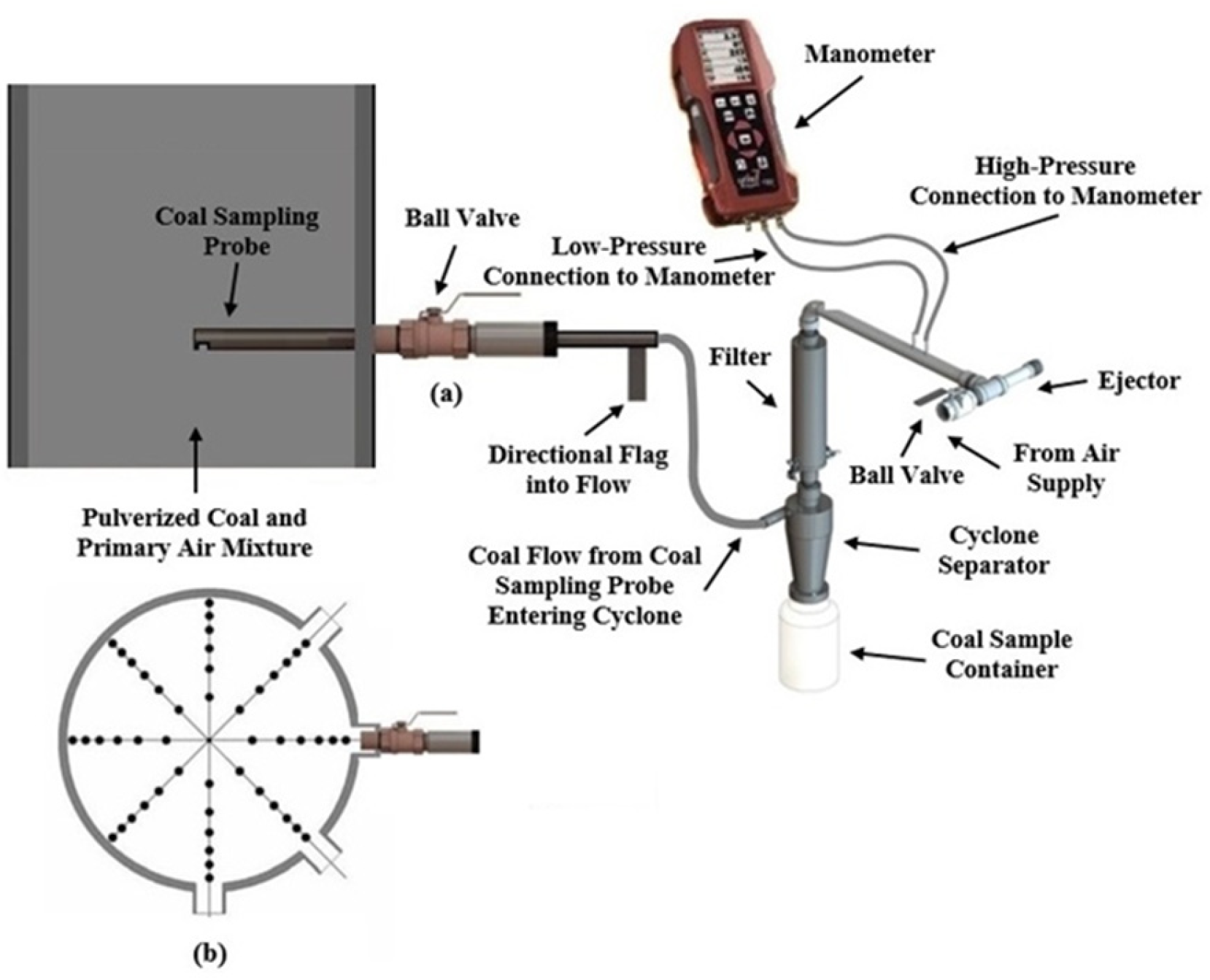
Figure 6.
(a) Camera setup for observing secondary air transformation; (b) plasma formation at 500 Nm³/h air flow rate after ignition.
Figure 6.
(a) Camera setup for observing secondary air transformation; (b) plasma formation at 500 Nm³/h air flow rate after ignition.
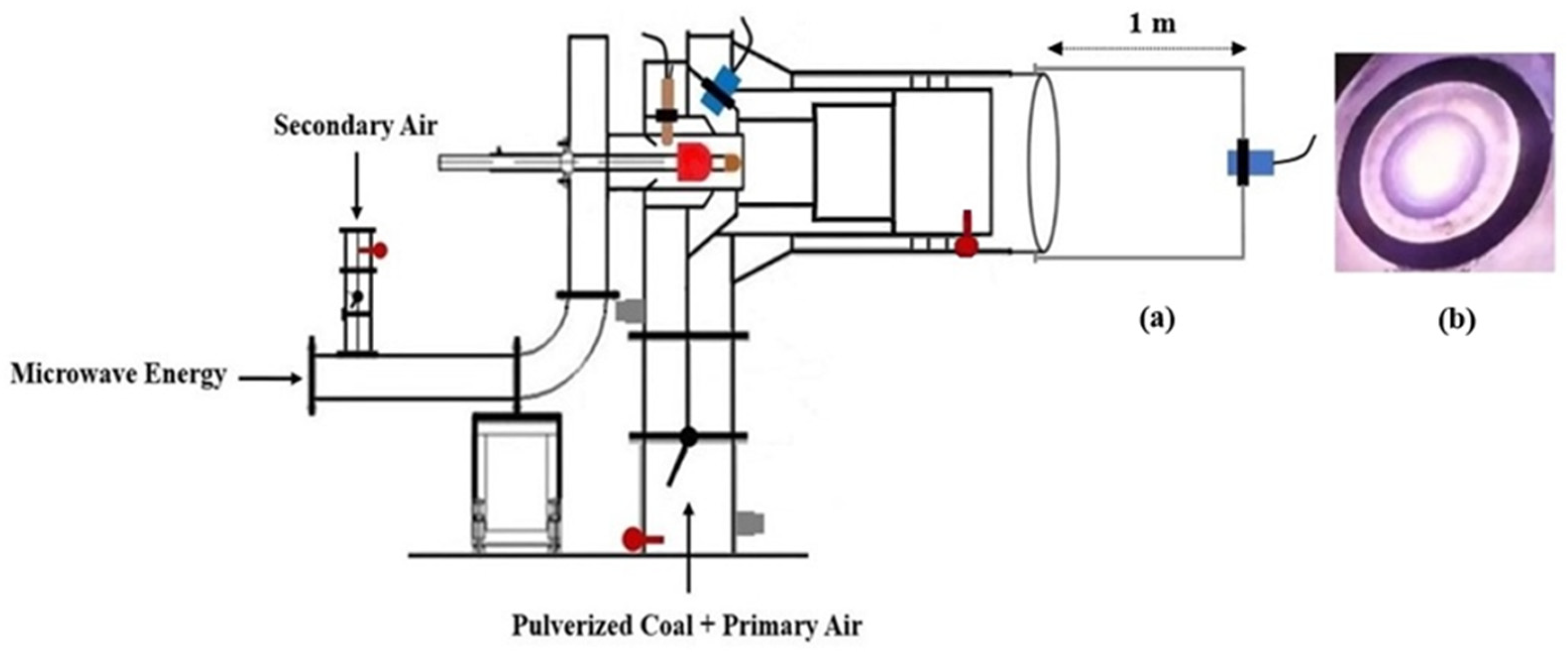
Figure 7.
Plasma flame temperatures were measured at the burner outlet under different secondary air flow rates and magnetron output power levels.
Figure 7.
Plasma flame temperatures were measured at the burner outlet under different secondary air flow rates and magnetron output power levels.
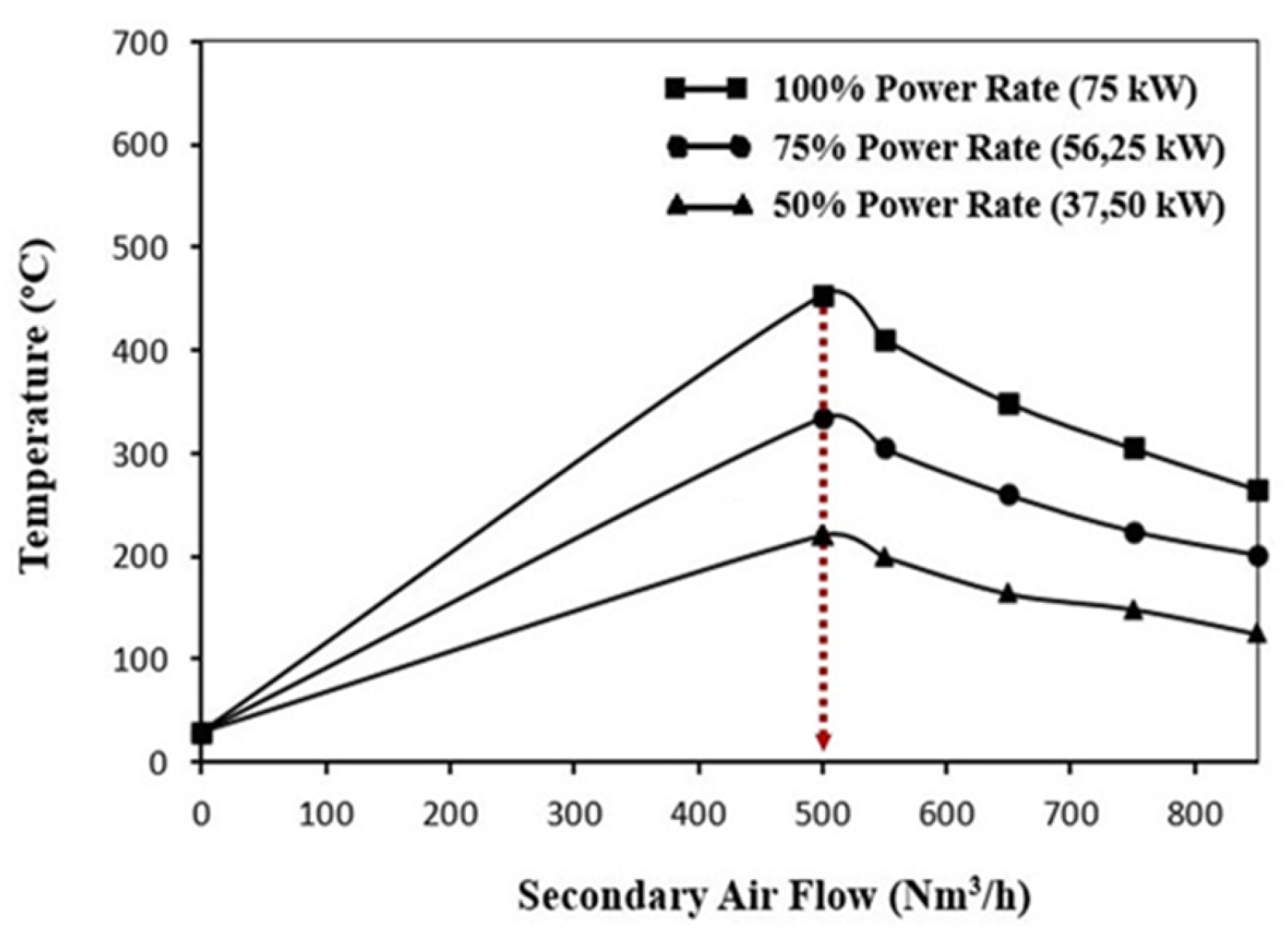
Figure 8.
The particle size distribution of pulverized coal based on M16 measurement shows that 61.14% of the particles are smaller than 90 µm.
Figure 8.
The particle size distribution of pulverized coal based on M16 measurement shows that 61.14% of the particles are smaller than 90 µm.
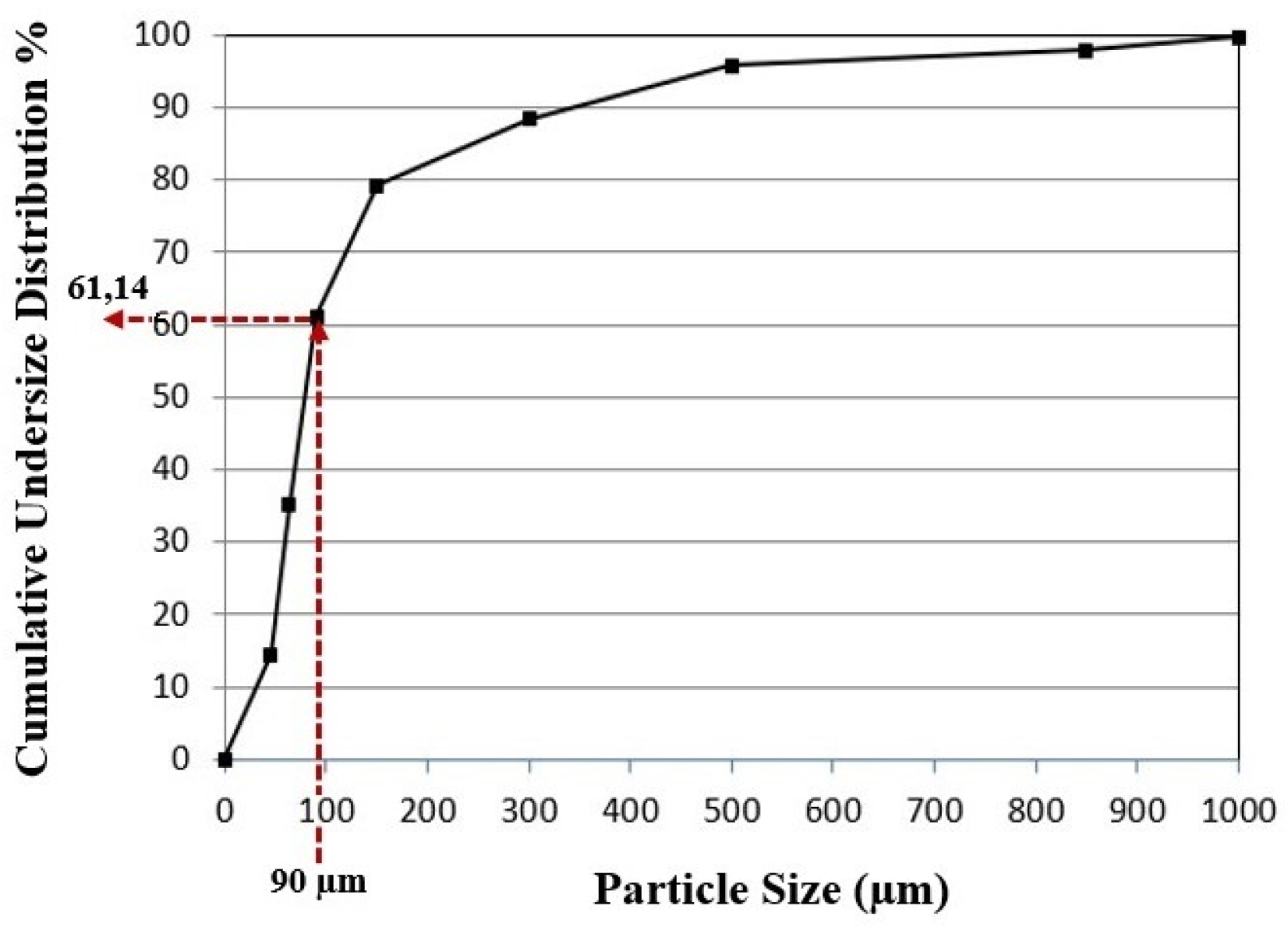
Figure 9.
Flame extending up to 4 meters at a coal feed rate of approximately 3000 kg/h.
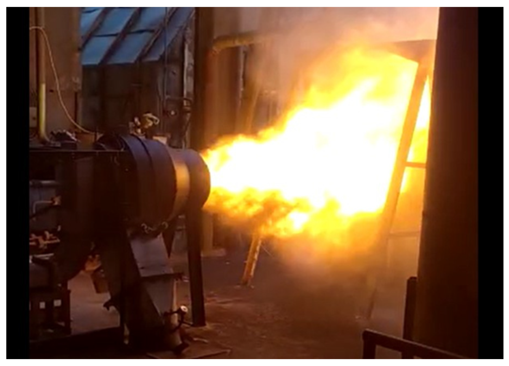

Table 1.
Secondary Air Measurements.
| Parameters | M1 | M2 | M3 | M4 | M5 | M6 | M7 | M8 |
| static pressure [Pstatic, Pa] | 181 | 193 | 205 | 222 | 225 | 230 | 234 | 251 |
| temperature [T, oC] | 30 | 30 | 30 | 30 | 30 | 30 | 30 | 30 |
| density [ρ, kg/m3] | 1,08 | 1,08 | 1,08 | 1,08 | 1,08 | 1,08 | 1,08 | 1,08 |
| *differential pressure [ΔPdifferential, Pa] | 7,44 | 15,13 | 24,90 | 30,56 | 36,74 | 51,68 | 68,60 | 88,20 |
| velocity [V, m/s] | 3,93 | 5,52 | 7,08 | 7,84 | 8,59 | 10,20 | 11,77 | 13,32 |
| secondary air flow [Q, Nm3/h] | 250 | 352 | 451 | 500 | 548 | 650 | 751 | 848 |
*The differential pressure values represent the average values measured at each port.
Table 2.
Primary Air Measurements.
| Parameters | M9 | M410 | M511 | M412 | M513 | M414 | M515 |
| damper position [o] | 25 | 25 | 25 | 50 | 50 | 75 | 75 |
| static pressure [Pstatic, Pa] | 325 | 362 | 410 | 384 | 367 | 399 | 341 |
| temperature [T, oC] | 33 | 33 | 33 | 33 | 33 | 33 | 33 |
| density [ρ, kg/m3] | 1,14 | 1,14 | 1,14 | 1,14 | 1,14 | 1,14 | 1,14 |
| *differential pressure [ΔPdifferential, Pa] | 292 | 190 | 297 | 591 | 1923 | 962 | 1381 |
| velocity [V, m/s] | 23,57 | 19,02 | 75,30 | 33,58 | 60,57 | 42,84 | 51,31 |
| secondary air flow [Q, Nm3/h] | 5998 | 1210 | 4790 | 2140 | 3860 | 2730 | 3270 |
*The differential pressure values represent the average values measured at each port.
Table 3.
Primary air-pulverized coal measurements.
| Parameters | M16 | M417 | M518 |
| damper position [o] | 25 | 25 | 25 |
| static pressure [Pstatic, Pa] | 285 | 362 | 410 |
| temperature [T, oC] | 27 | 27 | 27 |
| density [ρ, kg/m3] | 1,16 | 1,16 | 1,16 |
| *differential pressure [ΔPdifferential, Pa] | 278 | 190 | 297 |
| velocity [V, m/s] | 22,81 | 18,23 | 72,31 |
| primary air flow [Q, Nm3/h] | 5803 | 1160 | 4600 |
| total number of ports used in the measurement [TNP] | 4 | 3 | 3 |
| number of sampling points at each port [NSP] | 12 | 6 | 6 |
| sampling time at each point [s] | 30 | 30 | 30 |
| total sampling weight [g] | 2164 | 1079 | 3742 |
| total coal flow [kg/h] | 2941 | 652 | 2261 |
*The differential pressure values represent the average values measured at each port.
Table 4.
Proximate analysis of the Soma Coal sample taken from the pipe during the M16 measurement.
| Parameters | As Received Basis | Dry Basis | Dry Ash Free Basis |
| moisture [%] | 22,4 | - | - |
| ash [%] | 32,1 | 41,4 | - |
| volatile matter [%] | 36,0 | 46,4 | 79,1 |
| fixed carbon [%] | 9,5 | 12,2 | 20,9 |
| total sulfur [%] | 0,9 | 1,2 | - |
| gross calorific value [kcal/kg] | 2662 | 3428 | 5851 |
Table 5.
Particle Size Analyses.
| Particle Size [µm] | Weight [%] | Cumulative UndersizeDistribution [%] | Cumulative OversizeDistribution [%] |
| +1000 | 0,21 | 100,00 | 0,21 |
| 1000-850 | 1,89 | 99,79 | 2,10 |
| 850-500 | 2,12 | 97,90 | 4,22 |
| 500-300 | 7,4 | 95,78 | 11,62 |
| 300-150 | 9,18 | 88,38 | 20,80 |
| 150-90 | 18,06 | 79,20 | 38,86 |
| 90-63 | 26,08 | 61,14 | 64,94 |
| 63-45 | 20,59 | 35,06 | 85,23 |
| 45-00 | 14,47 | 14,47 | 100,00 |
| total | 100,00 |
Disclaimer/Publisher’s Note: The statements, opinions and data contained in all publications are solely those of the individual author(s) and contributor(s) and not of MDPI and/or the editor(s). MDPI and/or the editor(s) disclaim responsibility for any injury to people or property resulting from any ideas, methods, instructions or products referred to in the content. |
© 2025 by the authors. Licensee MDPI, Basel, Switzerland. This article is an open access article distributed under the terms and conditions of the Creative Commons Attribution (CC BY) license (http://creativecommons.org/licenses/by/4.0/).
Copyright: This open access article is published under a Creative Commons CC BY 4.0 license, which permit the free download, distribution, and reuse, provided that the author and preprint are cited in any reuse.


