
Submitted:
22 April 2025
Posted:
22 April 2025
You are already at the latest version
Abstract
The paper provides an analysis of the energy efficiency of the swing drive system of hydraulic excavators, which integrally includes a hydraulic motor and a planetary reducer. The indicator of the drive’s energy efficiency is determined based on the efficiency of the hydraulic motor and the planetary reducer. The efficiency of the hydraulic motor is defined as a function of the specific flow, pressure, and the number of revolutions of the hydraulic motor. The efficiency of the reducer is determined using structural analysis of planetary gearboxes and the moment method. As an example, the results of a comparative analysis of the energy efficiency of the swing drive of a tracked hydraulic excavator, weighing 16,000 kg and having a bucket volume of 0.6 m³, are presented. From the set of possible generated variant solutions of the drive, obtained through the synthesis process based on the required torque and platform rotation speed, two extreme drive variants were selected for the analysis. The first drive variant uses a hydraulic motor with low specific flow and a three-stage reducer with a higher transmission ratio, while the second variant uses a hydraulic motor with high specific flow and a two-stage reducer with a lower transmission ratio. The obtained results of the comparative analysis of the drive's energy efficiency are presented depending on the change in the required torque and the number of revolutions of the platform.
Keywords:
hydraulic excavators
; swing drive
; energy efficiency
1. Introduction
Due to the global environmental crisis, in recent years the demands for energy savings and green gas emissions in the construction machinery sector have increased significantly, while simultaneously preserving the performance, safety and reliability of the machines [1]. Modern construction machines such as excavators, loaders and cranes have significant losses in their drive systems, especially when hydraulically actuated. The energy efficiency of hydraulic systems is estimated at around 54%, while the efficiency of the entire machine is only 10% [2]. Hydraulic excavators are a prime focus for energy-saving innovations. A comprehensive review by Do et al. [3] surveyed state-of-the-art energy regeneration techniques for excavators, which can help reduce energy consumption and pollution in hydraulic excavators. Building on these insights, recent studies have introduced innovative hybrid architectures and energy recovery systems. Nguyen et al. [4] introduced an innovative hybrid powertrain and energy management system for hydraulic excavators. Their system incorporates hydrostatic transmission into the hybrid powertrain. Experimental validation on a lab-scale excavator platform showed a 9.44% reduction in overall energy consumption compared to a conventional system. Singh et al. [5] presented a comprehensive review of sustainable energy solutions for hydraulic excavators alongside a new regeneration concept for the swing drive. They surveyed technologies like hybrid systems and they proposed system which achieved about 13.2% improvement in energy savings and a 97.5% energy regeneration efficiency in simulations.
Ge et al. [6] developed an electro-hydraulic excavator system equipped with a displacement variable pump driven by a speed variable electric motor, achieving significant energy savings-up to 33% under partial load conditions. On the other hand, Li et al. [7] proposed an electro-hydraulic hybrid drive system combining an electrically active driving system and a hydraulically passive driving system, which resulted in a 70% reduction in energy consumption during a single boom lifting-lowering cycle. Huang et al. [8] introduced a redesigned hydraulic motor for swing drives, aiming to assess how motor parameters influence energy efficiency. The proposed dual-source hydraulic motor combines an energy recovery unit with the primary drive unit, creating two separate hydraulic circuits to minimize energy loss during braking—a frequent issue in traditional systems. A key design metric, the displacement ratio, defined as the ratio between the displacements of the two hydraulic circuits, plays a critical role in determining motor performance and overall system behavior. The study highlights a substantial decrease in energy consumption by the hydraulic pump in the main drive when using the dual-source setup compared to a standard configuration. In contrast, conventional swing drive systems rely on the operator's reaction speed for productivity and precise positioning during rotation. To address this, another study [9] proposes a combined position and speed control method that retains the existing operational interface but uses the desired rotation angle or position as the input for a closed-loop control system. Furthermore, to enhance braking dynamics, the strategy applies the principle of energy balance by adjusting the valve opening size throughout the swing motion.
So, most studies demonstrate a clear trend: by combining hydraulic energy storage [10,11,12] (accumulators, regenerative units) with intelligent hybrid powertrains [13,14,15] and control strategies [16,17,18,19], excavators can dramatically improve their energy efficiency.
Compared to these advanced system-level solutions, this study focuses on the analysis aimed at optimizing the conventional drive configuration, particularly the hydraulic motor and planetary gear reducer of the swing drive in hydraulic excavators—with the objective of enhancing overall efficiency through appropriate component selection and the alignment of component parameter ratios for the entire operating cycle, including phases such as digging material, moving, unloading, and returning to the initial position. Rotation has been identified as a key phase [20] that significantly influences the total cycle duration and fuel consumption, especially in hydraulic excavators. The analysis of the size ratio of components that make up the drive mechanism for rotating the platform of hydraulic excavators plays a key role in determining the dynamic stability and energy efficiency of the drive. Thus, our previous study [21] demonstrated the influence of component size ratio parameters on the dynamic load and dynamic stability of the drive.
2. Mathematical Model of the of the Swing Drive of Excavators
For the development of a mathematical model of the slewing platform drive, a hydraulic crawler excavator with a deep bucket (Figure 1a) was considered. The following notations were introduced: L1 – excavator tracks, L2 – slewing platform, L3 – boom, L4 – arm, and L5 – bucket. The actuators of the manipulator drive mechanisms are the hydraulic cylinders of the boom - c₃, the arm- c₄, and the bucket - c₅. The slewing platform drive consists of a hydraulic motor 2.3 (Figure 1b), a gearbox 2.4, and an axial bearing 2.5. The drive hydraulic motor is supplied via distributor 2.2 by the hydraulic pump 2.1, which is powered by diesel engine 1 through the power splitter 1.2 and the flexible coupling 1.1. By rigidly connecting the gearbox housing to the untoothed ring of the axial bearing for the slewing platform L2, and by rotating the gear z24 on the gearbox output shaft in engagement with the stationary toothed ring z25 of the axial bearing, which is fixed to the excavator’s undercarriage L1, the rotation of the platform is achieved.
The parameters of the drive mechanism function for the excavator’s slewing platform are the output torque M₂ and the rotational speed n₂ of the platform, defined by the following equations [21]:
where: qpmax, qmmax – the maximum specific flow of the hydraulic pump and the hydraulic motor, p, po – the pressure in the extension and retraction duct of the hydraulic motor, np – the number of the hydraulic pump revolutions, ir, ηr – the transmission ratio and the degree of efficiency of the reducer, ηpv, ηpm, ηmv, ηmm – the volumetric and mechanical degree of efficiency of the hydraulic pump and the hydraulic motor, εp=qp/qpmax – the hydraulic pump regulation range, εm=qm/qmmax – the hydraulic motor regulation range, ηl – the degree of efficiency between the reducer and the axial bearing.
2.1. Synthesis of the Drive System
Equations (1) and (2) show that for the same desired parameters of the slewing platform drive function, different drive variants can be generated through the synthesis process by varying the pressure and flow rate of the hydraulic pump, as well as by changing the displacement of the hydraulic motor and the gear ratio of the gearbox.
In the process of generating drive variants, the first synthesis step determines the maximum output torque Mrmax at the gearbox output shaft of the drive mechanism, based on the maximum required torque of the slewing platform M2max:
Through the further synthesis process, for the selected gearbox model, possible variant solutions of the slewing platform drive mechanism are generated by varying the rotational speed np, pressure p, and the available specific displacements of the hydraulic pump qp, along with the specific displacements of the hydraulic motor qm and the gear ratios of the gearbox ir, in order to satisfy the following conditions:
where: kМ, kn - coefficients of the allowable range for the torque and rotational speed of the slewing platform.
2.2. Energy Analysis of the Efficiency of the Swing Drive Transmission
As one of the criteria for evaluating the generated variant solutions with identical output functional parameters but different transmission parameters, an energy analysis of the efficiency of the swing drive transmission was performed.
The overall efficiency of the transmission is taken as the indicator of the energy efficiency of the drive transmission in the excavator's swing mechanism:
where: ηmu -efficiency of the hydraulic motor, ηr - efficiency of the gearbox transmission.
The efficiency of the hydraulic motor is defined as the product of its volumetric efficiency ηₘᵥ and mechanical efficiency ηₘₘ:
depending on the flow losses and torque losses of the hydraulic motor, determined by the correlation expressions [22]:
where: h1m, h2m, kom, k1m, k2m – correlation constants for flow and torque losses, determined through testing for each hydraulic motor size.
The efficiency of the gearbox depends on the design concept of the gearbox structure. In the transmission assemblies of the swing drive mechanism for excavators of all sizes, planetary gearboxes are used, with one or more elementary planetary gear sets.
In principle, for all elementary planetary sets, the sun gear 1 (Figure 2) is connected to the input (driving) shaft, the planet gears 2 mesh with both the sun gear and the fixed ring gear 3, and the output (driven) shaft is part of the planet carrier 4.
The complex motion of the planetary set elements consists of a transmission (carrier) motion and a relative motion. Transmission motion is exhibited by elements (the sun gear and planet carrier) that rotate around the central axis of the planetary set, while the relative motion refers to all other elements (planet gears) of the transmission.
Previous research has shown that both theoretical and experimental methods are used in determining the efficiency of planetary gearboxes. Among the theoretical methods are the power loss method in the gear meshes of planetary sets and the Kreiner (moment) method, which, when calculating efficiency, consider only the friction losses that occur due to gear meshing [23,24,25]. By applying structural analysis of planetary gear trains and the moment method, the efficiencies of the generated variant solutions of the swing drive gearboxes were determined using the following ratio [26]:
where: irt - torque transmission ratio of the planetary gearbox considering friction losses in gear meshing, ir - torque transmission ratio of the gearbox without considering friction losses in gear meshing.
In determining the torque transmission ratios, the structural diagram of the gearbox-composed of symbols representing elementary planetary gear sets (Figure 2c) [26] - is used. The symbol of the elementary planetary gear set indicates one input energy flow with torque M₁ = 1, and two output energy flows with torques M₄ and M₃, which are related by the following ratio:
where: M₁ - unit input torque of the sun gear, M₃ - output torque on the fixed ring gear,M₄ - output torque on the planet carrier, is=z3/z1 - gear ratio defined as the number of teeth of the fixed ring gear to the sun gear, ηs - efficiency of the elementary planetary gear set accounting for friction in gear meshing [26]:
For a planetary gearbox with ns elementary planetary gear sets, the efficiency is determined by the following equation (Figure 2c):
When friction losses in gear meshing are not taken into account, the torque transmission ratio of the gearbox ir is determined, assuming the efficiencies of the elementary planetary gear sets ηsј =1. Based on the previously defined general mathematical model, a program was developed for generating variants of the excavator swing drive mechanism and for analyzing their energy efficiency, using the given functional parameters of the swing drive and data files containing the parameters of available drive component models.
3. Example of Drive Efficiency Analysis
As an example, by using the developed program, possible variants of the swing drive mechanism were generated, and their energy efficiencies were determined for a physical model of a hydraulic crawler excavator weighing 17,000 kg and equipped with a bucket volume of 0.6 m³.
The program utilized parameter files of available swing drive components, including: axial-piston hydraulic pumps with variable specific displacement, axial-piston hydraulic motors with constant specific displacement, and planetary gearboxes-configured according to the catalogs of Bosch Rexroth [27]. The size of the axial bearing in the swing drive was determined based on the bearing load spectrum during excavation operations across the entire working range of the excavator [28,29], and from parameter files of available axial bearings from the company RotheErde [30].
In generating the variant solutions of the swing drive, the functional parameters of the slewing platform and the known parameters of the diesel engine and axial bearing were specified (Table 2).
The specified number of swing drive mechanisms nc2 and the maximum rotational speed of the platform n2max, as well as the diesel engine speed range at rated power nеn=[nenp, nenk] and the hydraulic pump pressure range p=[pmin, pmax], were determined based on the results of a parametric analysis of hydraulic excavator models from leading global manufacturers that are similar in size (mass) to the analyzed physical model of the excavator.
The specified functional parameter of the swing drive - the maximum torque of the slewing platform M2mac, was determined based on the measured state variables of the observed physical excavator model during various manipulation tasks under real operating conditions [31]. The set of measured state variables included: displacements of the undercarriage, the slewing angle of the platform, kinematic lengths of the hydraulic cylinders of the manipulator drive mechanisms, pressures in the working lines of the manipulator hydraulic cylinders, and pressures in the hydraulic motor of the swing drive.
Based on these measured variables, among other things, the functional parameters of the excavator’s drive mechanisms were determined for 42 different manipulation tasks across the entire working range of the excavator.
For the selected manipulation task 5, the change in angular velocities (Figure 3a) and drive torques Mpi (Figure 3b) is presented for the swing drive mechanism (i = 2) and the manipulator drive mechanisms (i = 3, 4, 5) of the excavator during digging, material transfer, unloading, and return to a new digging position.
In this task, the maximum digging depth is 1,3m, and the slewing angle of the platform is 350, which corresponds to the most common operating conditions of the analyzed excavator model.
b) drive torques Mpi.
The changes in functional parameters show that the drive torque Mp2 of the swing drive mechanism is relatively small, during the manipulation task, compared to the drive torques of the boom Mp3, arm Mp4, and bucket Mp5 drive mechanisms of the manipulator.
Notably, the torque of the swing drive during the digging operation is negligible, as it is balanced by the lateral digging resistance acting perpendicularly on the outer surfaces of the bucket.
The maximum values of angular velocity and drive torque Мp2 of the swing platform occur during the transfer of the excavated material from the digging plane to the unloading plane, as well as during the return operation to a new digging position. The specified value of the maximum torque of the slewing platform M2max=50 kNm was determined based on the maximum torque of the slewing platform M2max=49,33 kNm (Figure 3b), which occurred at (t=15,87s), at the beginning of the acceleration phase during the return of the excavator manipulator from the unloading plane to a new digging plane, within manipulation task 5. Based on the specified functional parameters, compiled constraints, and the assembled data files of available drive component models, 94 possible variant solutions of the swing drive mechanism were generated for the observed excavator model using the developed program. From the set of possible swing drive mechanism solutions, two representative variants - VE10/1 and VE12/1 -were selected for a comparative analysis of transmission energy efficiency (Table 3). These variants differ significantly in their transformation and transmission parameters. Variant VE10/1 features a smaller hydraulic motor with a specific displacement of qm=32 cm3 and a three-stage gearbox with a higher transmission ratio of ir=91,13, whereas variant VE12/1 includes a larger hydraulic motor with a specific displacement of qp=80 cm3 and a two-stage gearbox with a lower transmission ratio of ir=31,36. Both drive variants are equipped with the same hydraulic pump with a maximum specific displacement of qp=80 cm3, with slight differences in maximum pressure and rotational speed, resulting in minor variations in output parameters-the maximum rotational speed and maximum torque of the slewing platform.
In the comparative energy analysis of the selected drive variants, for hydraulic motors with specific displacements of 32 cm³ and 80.4 cm³, the overall efficiencies were determined with sufficient accuracy (Equations 11, 12, 13) based on known flow loss and torque loss constants of hydraulic motors with specific displacements of 35 cm³ and 75 cm³ (Table 4).
The efficiencies ηᵣ of the planetary three-stage gearbox in drive variant VE10/1 and the planetary two-stage gearbox in variant VE12/1 were determined (Equation 14) using the moment method and the structural diagram of the gearbox (Figure 5).
The required gearbox parameters were defined based on 3D models of the corresponding gearboxes selected from the database of available gear units.
For the selected variant solutions, the overall transmission efficiencies ηᵤ (Figure 6) of both drive variants were determined by varying the hydraulic motor pressure (from 3 to 45 MPa) and flow rate (from 10 to 195 l/min).
The comparative analysis of the efficiencies of the selected variants was conducted as a function of the platform's rotational speed n₂ and torque M₂.
The analysis of the obtained results shows that the energy efficiency of the drive transmission variants differs significantly and changes depending on the functional parameters of the excavator platform rotation. In operating zones with higher load torques and lower platform rotational speeds (corresponding to material transfer operations from the digging plane to the unloading plane), higher efficiency values are achieved by the transmission of variant VE10/1, which uses a hydraulic motor with lower specific displacement and a gearbox with a higher transmission ratio.
Variant VE12/1, featuring a hydraulic motor with higher specific displacement and a gearbox with a lower transmission ratio, achieves higher efficiency at lower load torques and higher platform rotational speeds. This corresponds to return operations from the unloading plane to a new digging plane, under larger slewing angles, when higher platform rotational speeds can be achieved.
The analysis of the change in the platform rotation function parameters, obtained from measured state variables of the observed physical excavator model during operation under real working conditions, shows that during manipulation task 5, the maximum platform torque M2max = 49.33 kNm (Figure 3b) occurred at t= 15.87 s, when the angular velocity (rotational speed) of the platform was = 0.41 rad/s (n2=3.91 min⁻¹).
Additionally, during the same manipulation task, the maximum angular velocity (rotational speed) of the platform = 0.65 rad/s (n₂ = 6.21 min⁻¹) occurred at t = 16.87 s. In both cases, the angular velocity (rotational speed) values were significantly lower than the maximum achievable angular velocity = 1.25 rad/s (n₂max = 12 min⁻¹) that the swing platform can reach with the selected drive variants.
The results of the energy analysis of the selected swing drive variants show that, for the most common excavator working operations—characterized by lower angular velocities and higher slewing torques—drive variants with hydraulic motors of lower specific displacement and gearboxes with higher transmission ratios exhibit higher efficiency levels.
However, for the final selection of the optimal swing drive solution for hydraulic excavators using a multi-criteria decision-making process, in addition to energy efficiency, other criteria should also be considered, including drive dynamic stability, cost, weight, design, and sustainability requirements.
4. Conclusions
The paper presents a procedure for the synthesis and energy efficiency analysis of a general model of the drive mechanism for rotating the platform of hydraulic excavators.
The drive efficiency was defined as the key indicator of energy performance, based on which a comparative analysis was conducted for drive variants with different component sizes but identical output parameters of the platform slewing function.
Using the developed synthesis program, based on the specified functional parameters of the platform drive and the parameter files of available drive components, possible drive variants were generated for a hydraulic excavator with a mass of 17,000 kg. The input parameters for the synthesis process were defined based on test results obtained from the selected excavator model operating under real working conditions. From the set of generated variants, two representative swing drive configurations were selected: one with a hydraulic motor of low specific displacement and a three-stage gearbox with a high transmission ratio, and the other with a hydraulic motor of high specific displacement and a two-stage gearbox with a lower transmission ratio.
The results of the comparative analysis show that the overall drive efficiency strongly depends on the selected transformation and transmission parameters. The variant with a hydraulic motor of lower specific displacement and a higher transmission ratio demonstrated higher efficiency under higher load torques and lower rotational speeds, whereas the other variant was more efficient at higher speeds and lower loads. These analysis results highlight the importance of selecting appropriate drive components with which the same excavator model can be equipped, in order to maximize the energy efficiency of the drive system. The proposed methodology, which integrates the modeling of hydraulic and mechanical efficiency, can serve as a useful tool in the design and selection of energy-efficient swing drive systems.
Future research may expand this approach by incorporating control strategies aimed at further improving energy efficiency under various operating conditions.
Author Contributions
Conceptualization, V.J. and D.J.; methodology, D.J.; software, V.J.; validation, V.J., D.J. and D.M.; formal analysis, V.J.; investigation, V.J.; resources, N.P. and B.N.; data curation, V.J.; writing—original draft preparation, V.J.; writing—review and editing, D.J. and D.M.; visualization, N.P. and B.N.; supervision, D.M.; funding acquisition, D.M. All authors have read and agreed to the published version of the manuscript.
Funding
This research was financially supported by the Ministry of Science, Technological Development and Innovations of the Republic of Serbia (Contract No. 451-03-137/2025-03/200109).
Data Availability Statement
Data are contained within the article.
Conflicts of Interest
The authors declare no conflicts of interest.
References
- Babaeimorad, S.; Fattahi, P.; Fazlollahtabar, H.; Shafiee, M. An integrated optimization of production and preventive maintenance scheduling in industry 4.0. Facta Univ. Ser. Mech. Eng. 2024, 22, 711–720. [Google Scholar] [CrossRef]
- Lodewyks, J.; Zurbrügg, P. Decentralized energy-saving hydraulic concepts for mobile working machines. 10th Int. Fluid Power Conf 2016, 1-2, 79–87. [Google Scholar]
- Do, T.C.; Dang, T.D.; Dinh, T.Q.; Ahn, K.K. Developments in energy regeneration technologies for hydraulic excavators: A review. Renew. Sustain. Energy Rev. 2021, 145, 111076. [Google Scholar] [CrossRef]
- Nguyen, V.H.; Do, T.C.; Dang, T.D.; Ahn, K.K. Improving the efficiency of hybrid hydraulic excavators with a novel powertrain and energy management system. Energy 2025, 323, 135766. [Google Scholar] [CrossRef]
- Singh S, Kumar A, Thakur S. Sustainable energy solutions for hydraulic excavators: A comprehensive review and novel energy regeneration approach. Proceedings of the Institution of Mechanical Engineers, Part E. 2025, 0. [Google Scholar]
- Ge, L.; Quan, L.; Zhang, X.; Zhao, B.; Yang, J. Efficiency improvement and evaluation of electric hydraulic excavator with speed and displacement variable pump. Energy Convers. Manag. 2017, 150, 62–71. [Google Scholar] [CrossRef]
- Li, Z.; Wang, C.; Quan, L.; Hao, Y.; Ge, L.; Xia, L. Study on energy efficiency characteristics of the heavy-duty manipulator driven by electro-hydraulic hybrid active-passive system. Autom. Constr. 2021, 125, 103646. [Google Scholar] [CrossRef]
- Huang, W.; Zhang, X.; Ge, L.; Quan, L. Dual Source Integrated Driving for Hydraulic Excavator Swing System. IEEE Access 2021, 9, 120755–120764. [Google Scholar] [CrossRef]
- Huang, W.; Quan, L.; Ge, L.; Xia, L. Combined velocity and position control of large inertial hydraulic swing mechanism considering energy balance of supply and demand. Autom. Constr. 2019, 106, 102899. [Google Scholar] [CrossRef]
- Nguyen, V.H.; Do, T.C.; Ahn, K.K. Hybrid powertrain with dual energy regeneration for boom cylinder movement in a hydraulic excavator. Automat. Constr. 2025, 171. [Google Scholar] [CrossRef]
- Tong, Z.; Jiang, Y.; Tong, S.; Zhang, Q.; Wu, J. Hybrid drivetrain with dual energy regeneration and collaborative control of driving and lifting for construction machinery. Automat. Constr. 2023, 150, 104806. [Google Scholar] [CrossRef]
- Yu, Y.; Do, T.C.; Yin, B.; Ahn, K.K. Improvement of energy saving for hybrid hydraulic excavator with novel powertrain. Int. J. Precis. Eng. Manuf.-Green Technol. 2023, 10, 521–534. [Google Scholar] [CrossRef]
- Nguyen, V.H.; Do, T.C.; Ahn, K.K. Investigation and optimization of energy consumption for hybrid hydraulic excavator with an innovative powertrain. Actuators 2023, 12, 382. [Google Scholar] [CrossRef]
- Truong, D.Q.; Marco, J.; Greenwood, D.; Harper, L.; Corrochano, D.G.; Yoon, J.I. Challenges of micro/mild hybridisation for construction machinery and applicability in UK. Renew. Sustain. Energy Rev. 2018, 91, 301–320. [Google Scholar] [CrossRef]
- Ge, L.; Quan, L.; Zhang, X.; Dong, Z.; Yang, J. Power matching and energy efficiency improvement of hydraulic excavator driven with speed and displacement variable power source. Chin. J. Mech. Eng. 2019, 32, 100. [Google Scholar] [CrossRef]
- Song, H.; Li, G.; Xiong, X.; Li, M.; Qin, Q.; Mitrouchev, P. A novel data fusion based intelligent identification approach for working cycle stages of hydraulic excavators. ISA Trans. 2024, 148, 78–91. [Google Scholar] [CrossRef]
- Precup,R. E.; Roman, R. C.; Hedrea, E. L.; Petriu, E. M.; Bojan-Dragos, C. A.; Szedlak-Stinean, A. I. Metaheuristic-based tuning of proportional-derivative learning rules for proportional-integral fuzzy controllers in tower crane system payload position control, Facta Univ. Ser. Mech. Eng. 2024, 22, 567 – 582.
- Kim, H.; Yoo, S.; Cho, S.; Yi, K. Hybrid control algorithm for fuel consumption of a compound hybrid excavator. Automat. Constr. 2016, 68, 1–10. [Google Scholar] [CrossRef]
- Zhang, S.; Minav, T.; Pietola, M.; Kauranne, H.; Kajaste, J. The effects of control methods on energy efficiency and position tracking of an electro-hydraulic excavator equipped with zonal hydraulics. Automat. Constr. 2019, 100, 129–144. [Google Scholar] [CrossRef]
- Kim, H.; Choi, J.; Yi, K. Development of supervisory control strategy for optimized fuel consumption of the compound hybrid excavator. Proc. Inst. Mech. Eng. D: J. Automob. Eng. 2012, 226, 1652–1666. [Google Scholar] [CrossRef]
- Jovanović, V.; Janošević, D.; Marinković, D.; Petrović, N.; Djokić, R. Analysis of Influential Parameters in the Dynamic Loading and Stability of the Swing Drive in Hydraulic Excavators. Machines 2024, 12, 737. [Google Scholar] [CrossRef]
- Modeling of Hydraulic Systems, Tutorial for the Hydraulics Library, Modelon 2013, https://uomosul.edu.iq/public/files/datafolder_2927/_20200216_095111_580.
- Arnaudov, K.; Karaivanov, D. The torque method used for studying coupled two-carrier planetary gear trains, Trans. of Famena 2013, XXXVII-1. [Google Scholar]
- Vrcan, Ž.; Troha, S.; Marković, K.; Marinković, D. Analysis of complex planetary gearboxes. Spectrum of Mechanical Engineering and Operational Research 2024, 1, 227–249. [Google Scholar] [CrossRef]
- Tica, M.; Vrcan, Ž.; Troha, S.; Marinković, D. Reversible planetary gearsets controlled by two brakes, for internal combustion railway vehicle transmission applications, Acta Polytec. Hung. 2023, 20, 95–108. [Google Scholar]
- C. Jodder, Dr. J. Saha: Structural analysis of three stage coupled planetary gear train and determination of efficiency, Int. Journal of Eng. Res. 2016, 5, 746–748.
- Bosch Rexroth, Available online: https://store.boschrexroth.com/Hidraulika?cclcl=en_HU, Available online: https://www.boschrexroth.com/en/hu/search.html?dnavs=DC_mediatype%3Adc_media_type_manual&q=79039-01-B&c=hu&lang=en&s=download.
- Jovanović, V.; Marinković, D.; Janošević, D.; Petrović, N. Influential Factors in the Loading of the Axial Bearing of the Slewing Platform Drive in Hydraulic Excavators. Tehnički Vjesnik - Tehnical Gazette 2023, 30, 158–168. [Google Scholar]
- Jovanović, V. , Marinković, D., Petrović, N., Stojanović, D. The Load Spectrum of Axial Bearing of Hydraulics Excavator with Shovel Attachment. J. Eng. Manag. Syst. Eng. 2024, 3, 175–182. [Google Scholar]
- Rothe Erde, Available online: https://www.thyssenkrupp-rotheerde.com/en/products/slewing-bearings.
- Janošević, D.; Pavlović, J.; Jovanović, V.; Petrović, G. A numerical and experimental analysis of the dynamic stability of hydraulic excavators, Facta Univ. Ser. Mech. Eng. 2018, 16, 157–170. [Google Scholar]
Figure 1.
a) Hydraulic crawler excavator, b) Swing drive of hydraulic excavators with an open hydrostatic circuit.
Figure 1.
a) Hydraulic crawler excavator, b) Swing drive of hydraulic excavators with an open hydrostatic circuit.
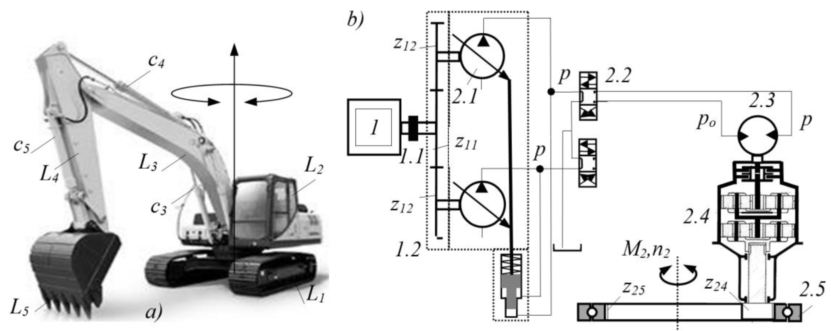
Figure 2.
Structural analysis of a planetary gearbox: a) elementary planetary gear set, b) symbolic representation, c) structural diagram of a three-stage planetary gearbox with elementary planetary sets [26].
Figure 2.
Structural analysis of a planetary gearbox: a) elementary planetary gear set, b) symbolic representation, c) structural diagram of a three-stage planetary gearbox with elementary planetary sets [26].
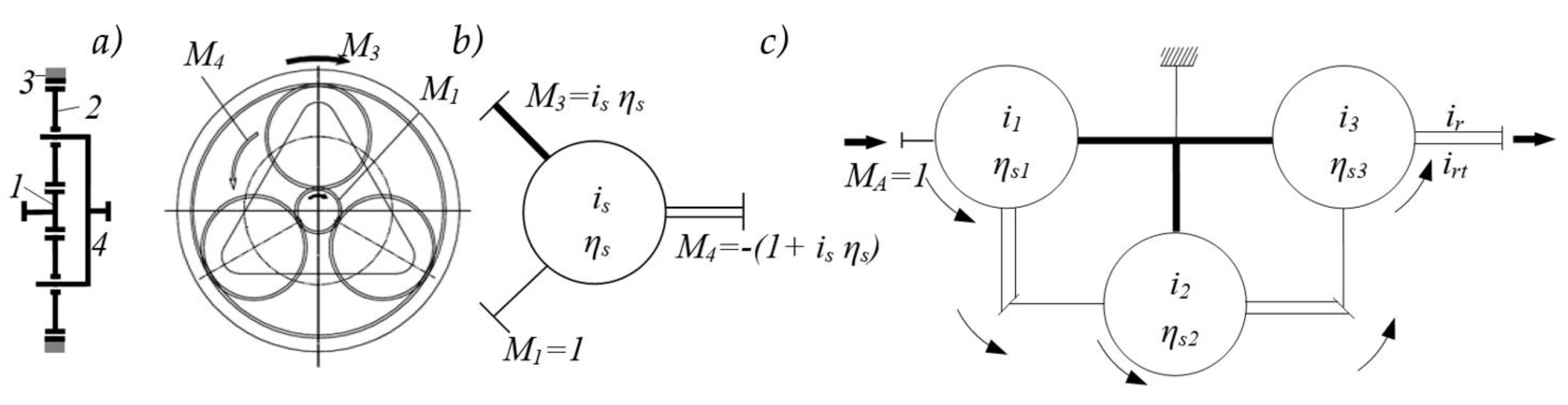
Figure 3.
Change in functional parameters of the excavator drive mechanisms during manipulation task 5: a) angular velocities
Figure 3.
Change in functional parameters of the excavator drive mechanisms during manipulation task 5: a) angular velocities
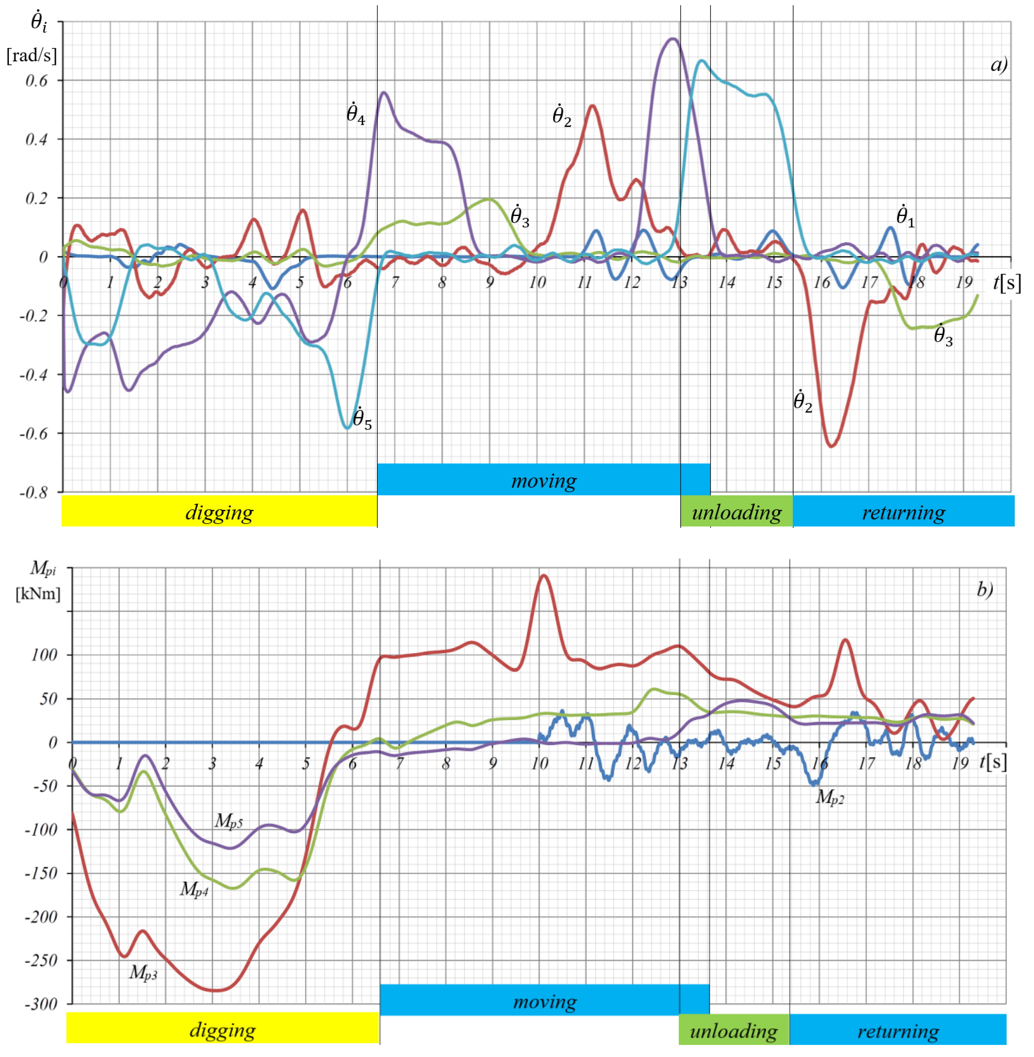
Figure 5.
Efficiencies of planetary gearboxes: а) three-stage gearbox, drive variant VE10/1, b) Two-stage gearbox, drive variant VE12/1.
Figure 5.
Efficiencies of planetary gearboxes: а) three-stage gearbox, drive variant VE10/1, b) Two-stage gearbox, drive variant VE12/1.
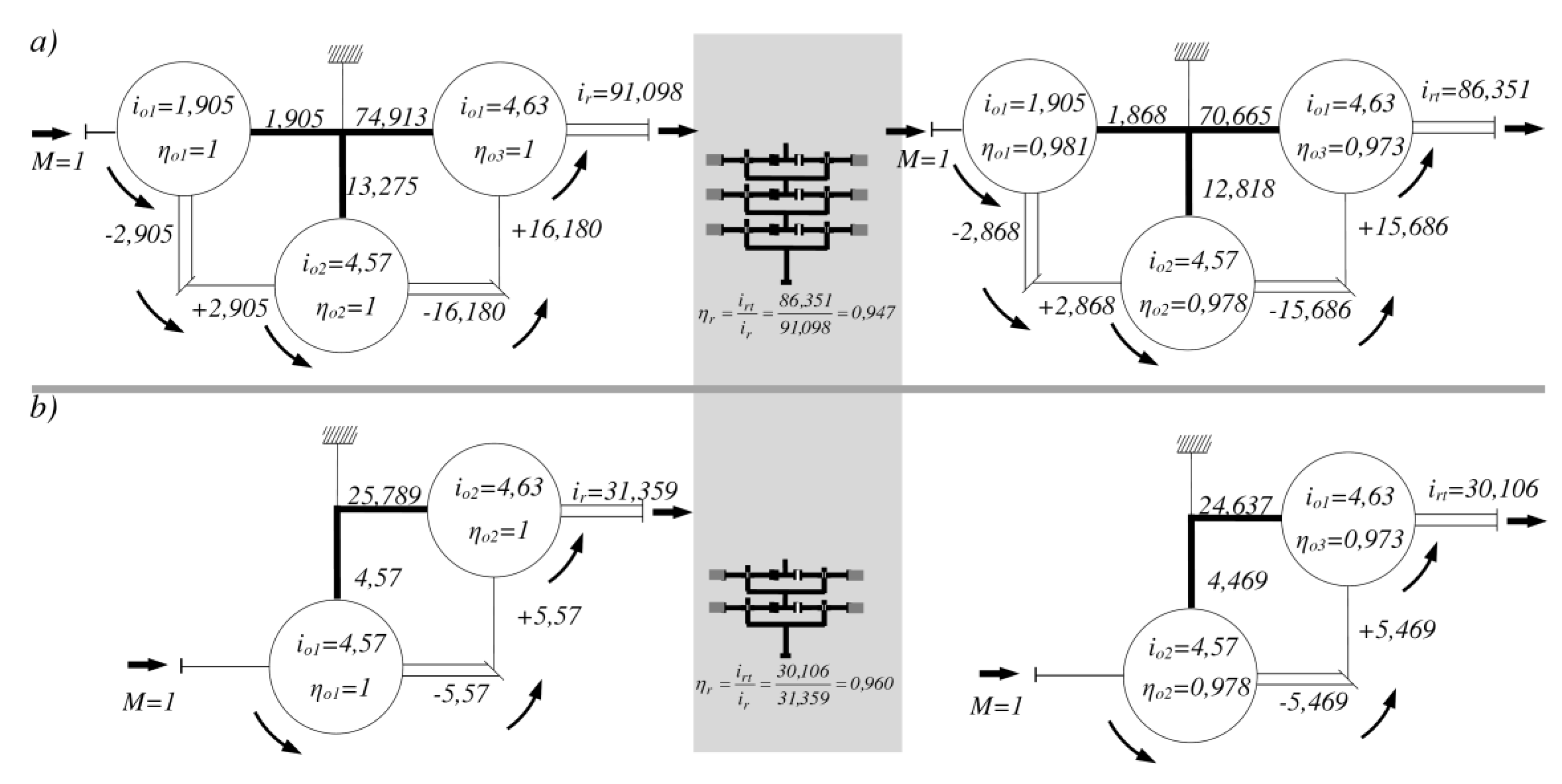
Figure 6.
Efficiencies of the transmission: а) drive variant VE10/1, б) drive variant VE12/1, c) both drive variants VE10/1 and VE12/1 .
Figure 6.
Efficiencies of the transmission: а) drive variant VE10/1, б) drive variant VE12/1, c) both drive variants VE10/1 and VE12/1 .
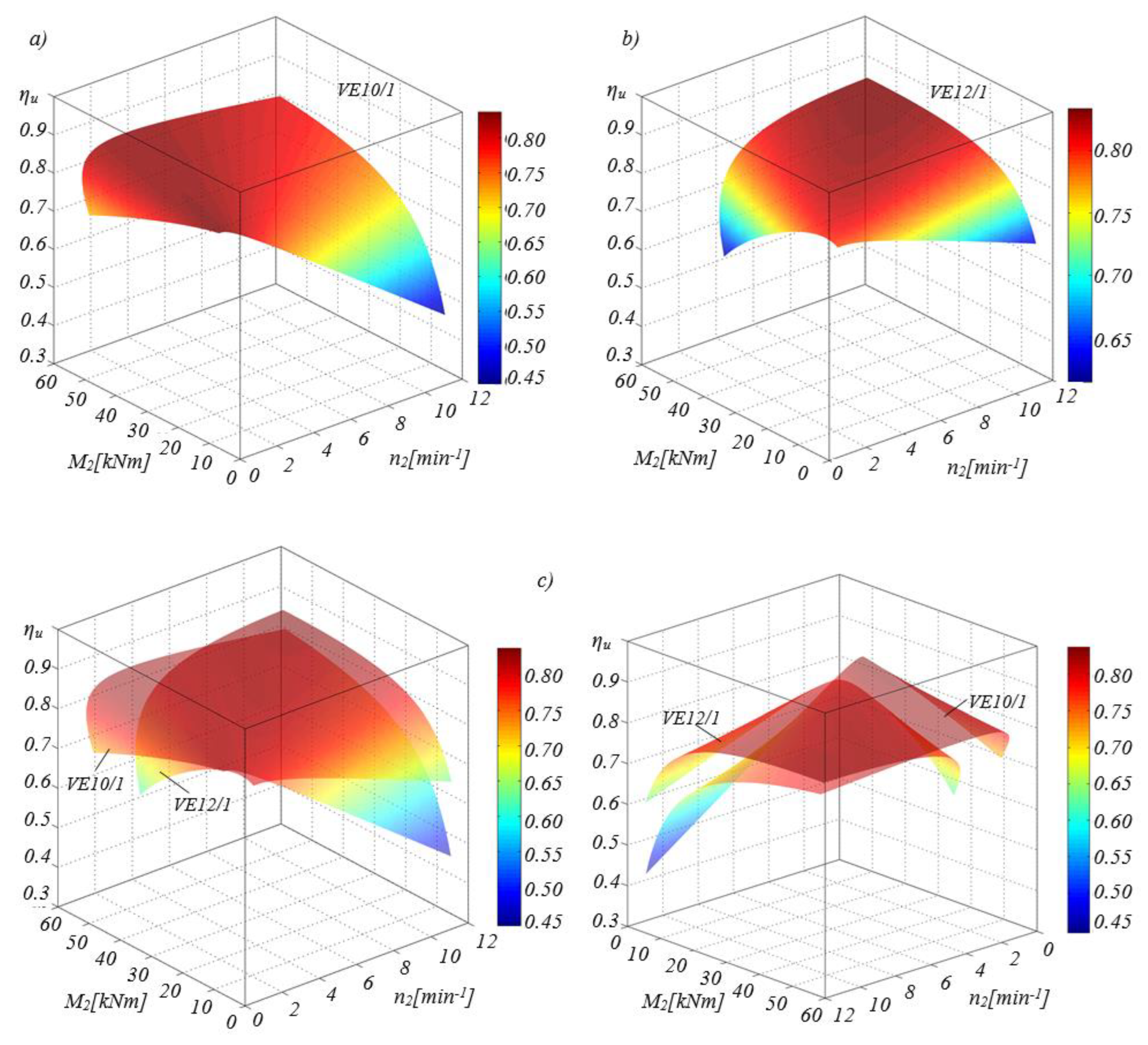

Table 2.
Functional Parameters of the Swing Mechanism for the Analyzed Excavator Model.
| Parameters | Symbol | Unit | Value |
| Maximum torque of the slewing platform | M2max | kNm | 50 |
| Maximum rotational speed of the slewing platform | n2max /(θ2max) | min-1/(rad/s) | 12/(1,25) |
| Number of swing drive mechanisms | nc2 | - | 1 |
| Number of teeth on the ring gear of the axial bearing | z26 | - | 93 |
| Efficiency between the gearbox and the axial bearing | ηl | - | 0,96 |
| Diesel engine max speed range at rated power | nenp,nenk | min-1 | 2000-2100 |
| Transmission ratio range of the power splitter | iep,iek | - | 0,50-1,20 |
| Pressure range of the hydraulic pump | pmin,pmax | MPa | 20-45 |
Table 3.
Selected Drive Variants of the Swing Mechanism for the Analyzed Excavator Model.
| Variant / Number of Drives | Hydraulic pump | Hydraulic motor | Gearbox | Slewing platform | |||
| Specific displacement qp [cm3] |
Pressure p [MPa] |
Rotational speed np [min-1] |
Specific displacement qm [cm3] |
Transmission ratio ir |
Rotational speed n2 [min-1] |
Torque M2 [kNm] |
|
| VE10/1 | 80.00 | 23.00 | 2433.09 | 32.00 | 91.13 | 12.06 | 50.02 |
| VE12/1 | 80.00 | 26.00 | 2141.33 | 80.40 | 31.36 | 12.07 | 50.45 |
Table 4.
Correlation constants for losses in axial-piston hydraulic motors [22].
Table 4.
Correlation constants for losses in axial-piston hydraulic motors [22].
| Specific displacement of the hydraulic motor |
Flow loss constants | Torque loss constants | |||
|
qm cm3 |
h1m m3/sPa |
h2m m3/rad |
kom Nm |
k1m Nm/Pa |
k2m Nm/(rad/s) |
| 35 | 1,0565e-12 | 3,0393e-8 | -2,8465e-1 | 3,7989e-7 | 2,1217e-2 |
| 75 | 1,8576e-12 | 5,1773e-8 | 3,4105 | 4,7974e-7 | 6.9763e-2 |
Disclaimer/Publisher’s Note: The statements, opinions and data contained in all publications are solely those of the individual author(s) and contributor(s) and not of MDPI and/or the editor(s). MDPI and/or the editor(s) disclaim responsibility for any injury to people or property resulting from any ideas, methods, instructions or products referred to in the content. |
© 2025 by the authors. Licensee MDPI, Basel, Switzerland. This article is an open access article distributed under the terms and conditions of the Creative Commons Attribution (CC BY) license (http://creativecommons.org/licenses/by/4.0/).
Copyright: This open access article is published under a Creative Commons CC BY 4.0 license, which permit the free download, distribution, and reuse, provided that the author and preprint are cited in any reuse.


