Submitted:
18 October 2024
Posted:
18 October 2024
You are already at the latest version
Abstract
The conventional hydraulic system of excavators suffers from significant valve throttling losses and inadequate matching between the hydraulic power source and the load, which substantially impacts the overall energy consumption of the system and severely impedes the trends toward electrification and energy efficiency in construction machinery. To address this issue, a pump-controlled hydraulic cylinder system has been implemented to replace the original valve-controlled hydraulic system that utilizes a single pump with multiple actuators. Focusing on a specific model of electric-driven excavator arm as the research subject, we completed parameter matching design for the pump-controlled hydraulic cylinder system. Based on typical operating conditions of the boom, experimental results revealed how energy conversion efficiency and hydraulic pump speed are influenced by varying load power.Furthermore, control over hydraulic cylinder position was achieved by adjusting pump displacement. A combined control strategy involving both displacement adjustment and motor speed modulation to align with load power is applied within this boom's pump-controlled hydraulic cylinder system. Research findings indicate that this combined control approach enhances efficiency by approximately 18.9% compared to traditional variable speed pump-controlled hydraulic cylinder system, while the energy consumption is reduced by about 39% compared with the traditional valve-controlled hydraulic system. under the hydraulic pump pressure of p=16 MPa and a working flow demand of Q=85 L/min, the efficiency of the hydraulic pump increases first and then decreases, that is, the efficiency spaceΔη=26.7% can be improved in the speed range.This study holds both theoretical and practical significance for enhancing energy utilization efficiency across entire excavator systems as well as optimizing their configurations.
Keywords:
pump-controlled hydraulic cylinder
; Speed displacement control strategy
; Power matching
; efficiency
1. Introduction
Energy crisis has become an important issue restricting the further development of human technology, energy saving, green development has become a new important concept. The development of electrification of construction machinery has become an important trend [1]. The traditional single pump corresponds to the hydraulic system of multi-actuator excavator. Due to the load difference, the hydraulic system has serious throttle loss and overflow loss of valve port. The working condition of excavator is complex and changeable, and the power matching between power source and load is poor. Effectively improve the whole system energy consumption. The development of electrization provides the feasibility for the distributed hydraulic system. From the structure of the excavator, the traveling motor is decouples from the boom, bucket rod, bucket and rotary mechanism, so that each actuator can be controlled according to the volume speed regulation mode, eliminating the throttling loss caused by the load difference of multiple actuators, and the closed hydraulic system effectively reduces the corresponding pipeline and fuel tank volume.
In view of the problems such as low energy utilization rate and poor endurance caused by serious energy consumption loss and load power mismatch in the hydraulic system of the existing electric driven excavator, the pump-controlled hydraulic cylinder system scheme is adopted for the excavator motor arm, which can eliminate the throttle loss of the valve port from the system configuration and control the motor speed and hydraulic pump displacement. The real-time matching between the output power of the hydraulic drive unit and the demand power of the load can effectively reduce the power loss in the energy conversion process of the motor to the hydraulic pump.
The working condition of the boom changes frequently, and the mismatch between the output power and the load power of the hydraulic drive unit results in serious energy consumption loss. The analysis of dynamic energy consumption during working condition switching of the variable speed pump control system is of great significance for improving the global power matching of the system and reducing energy consumption. There have been many studies on the use of pump control system to drive excavator working devices,Hou Simin analyzed the position and velocity characteristics of the pump-controlled differential cylinder system by using double pumps to control the hydraulic cylinder system to drive the 37t excavator arm. The results showed that compared with the single pump-controlled differential cylinder, the position and velocity response characteristics of the modified double pump-controlled differential cylinder were improved, the system ran more smoothly, and the accumulator had a significant energy storage effect. The output energy consumption is reduced by about 40% and 44% respectively under no-load and on-load conditions. However, the influence of load change on system energy consumption is not considered [2]. Zhang Shuzhong et al. transformed the pump-controlled cylinder system for the working device of the excavator, and established simulation models of the traditional valve control system and the pump-controlled cylinder system respectively for the working device. Through analysis and comparison, the energy consumption of the excavator using the servo motor pump control cylinder under a typical cycle condition was about 65% less than that of the traditional valve control system. However, the motor speed is not controlled for load changes, so as to match the load with the power source [3]. Ren Wei designed a pump-controlled integrated hydraulic cylinder system for the excavator motor arm. The special cavity hydraulic cylinder eliminated unbalanced flow, recovered and utilized the boom potential energy, and the system ran smoothly and energy-saving effect was remarkable [4]. Cheng Donghong used an asymmetric pump to control a single lever hydraulic cylinder to achieve flow matching and applied it to the excavator arm, achieving good energy saving effect [5].
The pump controlled hydraulic cylinder system can effectively improve the energy utilization efficiency of the whole excavator, but the energy conversion efficiency of the motor to the hydraulic pump is different under different load power, and there are problems such as high-speed motor operation and large power loss under low load condition. According to the influence law of different load power on the energy conversion efficiency of motor-hydraulic pump, the corresponding control strategy is proposed, which can effectively improve the energy utilization efficiency of the whole excavator. Huang Haihong proved through experimental research that by controlling and adjusting the motor acceleration, the average energy consumption of the hydraulic system could be increased by 8% in a given working cycle, thus effectively improving the system efficiency [6]. In order to explore the energy consumption of the hydraulic system with variable speed and displacement compound volume speed regulation, Tian Qingqing designed and completed the monitoring platform design of the composite control hydraulic system, which can realize the dynamic parameter monitoring of the hydraulic system [7]. Aiming at the hydraulic system drive unit of molding equipment, Liu Xiaopeng proposed a power matching scheme under global working condition for variable speed motor to drive constant power pump, and effectively improved the operating efficiency of the hydraulic system through the control method of maximum efficient-optimal speed [8] Li Qiankun analyzed the energy consumption of the motor driven by the electric excavator and proposed a speed control method based on the optimal efficiency of the motor, so that the motor could meet the driving requirements and be in a high-efficiency working area during the operation of the electric excavator, thus reducing the energy loss during the operation of the system. Based on the analysis of energy consumption of motor and hydraulic pump for electric excavator, Shi Lingbo proposed the power matching method of motor and hydraulic pump under different working conditions [9].Zhang De proposed a combined speed and displacement control strategy based on the combination of optimal speed and displacement, aiming at the power matching problem between motor and hydraulic pump in the working process of the pump control motor hydraulic system [10].Liu Siqi modeled and analyzed the energy consumption of three-phase asynchronous motors and proposed an online search method for optimal flux linkage to optimize motor efficiency [11].
As for the research on the compound control strategy of speed and displacement, Wang Chengbin proposed a compound control method of displacement and rotational speed for pump-controlled differential hydraulic cylinder. Through simulation and experimental research, under the control of inner loop displacement and outer loop rotational speed, the dynamic response of pump-controlled differential cylinder system is faster than that under constant rotational speed, the time is shortened by 13.4%, and the system energy consumption can be reduced by about 3kW under low rotational speed and large displacement. However, the speed of the motor is not actively controlled according to the characteristics of the system energy consumption to further improve the efficiency of the system [12].Wang Haiyan established a closed pump-controlled hydraulic cylinder system with variable speed and displacement, and superimposed the control speed and displacement to effectively improve the response speed of the system. The simulation analysis of the overall system scheme was carried out from the open-loop control method, closed-loop control method and load characteristics respectively, and the results showed that the closed-loop speed control scheme could maintain a stable state. It is largely unaffected by load but does not take into account system energy consumption [13]. Zhao Tianhong adopted the distribution decoupling control strategy based on hydraulic pump efficiency for the variable speed and variable displacement pump-controlled hydraulic cylinder system to solve the nonlinear problem of control variable multiplication [14]. Zhao Jinbao proposed a control strategy based on working condition decoupling and a fuzzy gain scheduling control algorithm for electro-hydrostatic servo actuator under the combined control of speed and displacement. Simulation and experiments proved that the proposed composite control strategy can effectively improve the dynamic performance of the electro-hydrostatic actuator system [15]. The compensation loop of passive valve using hydraulic control check valve for flow compensation is simple and suitable for the working condition with small load direction change. The circuit using multiple pumps to compensate the unbalanced flow rate also has high stability, but the increase in the number of pumps leads to the increase in installed power [16]. With the development of control technology, the research on pump-controlled hydraulic cylinder system is more in-depth, especially the research on the control strategy of pump-controlled hydraulic cylinder, which makes the control accuracy and response performance of pump-controlled hydraulic cylinder be improved and more widely used PID control is widely used because of its strong adaptability and flexibility and easy implementation in practical applications [17]. Minav designed a fuzzy PID controller for the direct drive pump-controlled hydraulic cylinder system to make the system have better dynamic characteristics [18]. Perron applied the sliding mode controller to the pump-controlled hydraulic cylinder system, and the system robustness was significantly improved [19]. Lee Lian-Wang designed an adaptive fuzzy controller for the position control system of variable speed pump-controlled hydraulic cylinder, and proved that the system has good position control function through experimental research [20]. Wang Longke from the United States adopted the singularity perturbation theory to eliminate the fluctuation of the working commutation speed of the pump-controlled cylinder [21]. Kyoung Kwan Ahn of Ulsan University in South Korea adopted an adaptive backthrusting control algorithm for the pump control system, which significantly improved the robustness and anti-interference of the system [22]. In addition to the theoretical research on pump-controlled hydraulic cylinder technology, foreign experts have already had more achievements in the application of pump-controlled hydraulic cylinder technology in aerospace, robot control and other fields. American engineers applied variable speed and constant displacement pump-controlled hydraulic cylinder to fighter aircraft , and achieved good operation test results [23]. Bobrow and Desai applied pump-controlled hydraulic cylinders to robot platforms, reducing platform impact and improving control performance [24,25]. Foreign experts have already had more achievements in the application of pump-controlled hydraulic cylinder technology in aerospace, robot control and other fields. Bobrow and Desai applied pump-controlled hydraulic cylinders to robot platforms, reducing platform impact and improving control performance [26,27,28].
To sum up, foreign research on pump-controlled single-exit rod hydraulic cylinder system mainly focuses on the asymmetric flow balance of the system and the control strategy of the pump-controlled hydraulic cylinder system as well as the application and promotion of pump-controlled hydraulic cylinder technology, and certain achievements have been achieved in the theoretical research and practical application of pump-controlled hydraulic cylinder system.
A comprehensive control strategy integrating speed and displacement is proposed to optimize motor speed for load power matching, while simultaneously adjusting hydraulic pump displacement to facilitate closed-loop control of the hydraulic cylinder’s position. Based on the design outcomes from parameter matching in the boom pump control system, a simulation model for the pump control system has been developed in AMESim, alongside a corresponding control strategy model constructed in Simulink. Through co-simulation, we analyze both the control performance and energy consumption of the system. By applying sinusoidal and step displacement signals, it is demonstrated that the system exhibits excellent displacement tracking capabilities and robust dynamic response characteristics under this integrated control approach. Under different load, the energy conversion efficiency of the combined pump control system is improved compared with that of the variable speed and constant displacement pump control system. In a complete mining operation cycle, compared with the valve control system and the variable speed pump control boom system, the response time of the combined pump control boom system is increased, but the energy is greatly saved.
An experimental platform for energy consumption analysis of variable displacement hydraulic pump driven by variable speed motor is set up, and the energy-saving characteristics of the boom compound pump-controlled hydraulic cylinder system are verified experimentally. The experimental results show that the optimal speed under different load power makes the energy conversion efficiency of the motor-hydraulic pump the highest, and the trend of load power and optimal speed change is consistent with the theoretical analysis. The experiment preliminarily proves the rationality of the energy-saving characteristics of the composite pump-controlled hydraulic cylinder. Through the combined control strategy of speed and displacement, the boom can operate smoothly, and compared with the traditional valve control system and pump control system with only variable speed, the energy-saving effect is more significant. This research has theoretical and practical guiding significance for innovative configuration design of electric excavator system and promoting its electrification development process.
As illustrated in Figure 1, the variable speed motor drives a variable displacement hydraulic pump to regulate the hydraulic cylinder system. Serving as the power source for this system, motor 1 converts electrical energy into mechanical energy and transmits it to the hydraulic pump via a coupling mechanism. The hydraulic pump then transforms this mechanical energy into hydraulic energy, delivering high-pressure oil to the system. Variable displacement hydraulic pump 2 employs an electric proportional variable piston design. The system modulates working flow by adjusting both motor speed and hydraulic pump displacement. Accumulator 3 utilizes an air-bag accumulator that is sensitive, compact, lightweight and operates at low pre-charge pressure,it serves to supplement leakage from both the hydraulic pump and cylinder while balancing asymmetric flow rates within the system. Relief valve 4-1 functions to limit maximum pressure within the accumulator,additionally, pre-filled high-pressure oil in this accumulator compensates for unbalanced flow resulting from area discrepancies between two chambers of the hydraulic cylinder when reversing opens check valves 6-1 and 6-2. Relief valves 4-2 and 4-3 act as safety valves designed to restrict maximum pressure across both chambers of the hydraulic cylinder.
The control principle of the hydraulic cylinder system, which is driven by a variable speed motor and a fixed displacement pump, as illustrated in Figure 2. The position of the hydraulic cylinder is regulated in a closed-loop manner solely through adjustments to the motor speed. However, certain operational conditions present challenges such as inadequate matching between system power and load requirements, as well as low energy utilization efficiency.
The integrated control principle of speed and displacement is illustrated in Figure 3. The primary controller regulates the position of the hydraulic cylinder within a closed-loop system by modulating the displacement of the hydraulic pump. The system continuously monitors external load forces and the operational speed of the hydraulic cylinder via force sensors and speed sensors, computes the real-time load power exerted on the hydraulic cylinder, and adjusts motor speed accordingly to enhance system-load power compatibility while minimizing energy consumption for both the motor and pump.
2. Mathematical Model
2.1. Mathematical Model of the System
(1) three-phase asynchronous motor mathematical model
Equations (1) and (2) are the voltage equations of the motor.
Formula (3) is the torque equation of the motor.
Where is the stator resistance, is the number of poles of the motor, and are the stator voltage in the coordinate system, and are the stator flux in coordinate system, and are the stator and rotor current respectively in rotating coordinate system. is the moment of inertia on the motor spindle, is the load torque, is electromagnetic torque.
(2) Variable pump flow equation
Where, is the maximum displacement of hydraulic pump, is the ratio of the actual displacement to the maximum displacement, is the speed of hydraulic pump, is the leakage coefficient of hydraulic pump, is the external leakage coefficient of hydraulic pump, is the load pressure, Pi is the inlet pressure of the hydraulic pump.
(3) Continuity equation of hydraulic cylinder flow
Hydraulic cylinder rodless cavity flow continuity equation:
Where, is the rodless cavity flow rate, is the rodless cavity volume of hydraulic cylinder, β is the bulk elastic modulus of hydraulic oil, is the rodless chamber pressure of hydraulic cylinder, is leakage coefficient of hydraulic cylinder,Δp is the pressure difference between the two chambers of the hydraulic cylinder.
Hydraulic cylinder rod cavity flow continuity equation:
In the formula, is the flow rate of the hydraulic cylinder with rod cavity, is the volume of rod cavity of hydraulic cylinder, is the pressure of hydraulic cylinder with rod cavity, Δp is the pressure difference between the two chambers of the hydraulic cylinder.
(4) Hydraulic cylinder force balance equation
Where, F is the load force on the boom hydraulic cylinder, and are the pressure of the rodless cavity and the rodless cavity of the hydraulic cylinder respectively. and are the areas of rodless and rodless cavities of the boom, respectively. B is the viscous damping of hydraulic cylinder piston and load, is the friction force, m is the mass of moving parts.
(5) Accumulator equation
Thermodynamic equation of ideal gas in accumulator:
Where P1 is the pressure in the initial working state of the accumulator,V1 is the working volume in the initial state,P2 is the pressure in the working state of the accumulator, V2 is the working volume in the working state.
2.2. Variable Speed Motor Drive Variable Displacement Hydraulic Pump Energy Consumption Model
(1) Motor energy consumption model
In the analysis of a three-phase asynchronous motor, the leakage inductance between the rotor and stator sides is neglected, while the mutual inductance between these two components is taken into account. A motor loss model is developed within a two-phase rotating coordinate system. The primary contributors to motor losses include copper losses and iron losses.Additionally, stray losses and frictional losses during load variations are deemed relatively minor and thus disregarded in this comprehensive assessment. Consequently, the overall motor loss can be expressed as.
Among them,
Where, Te is the rated torque of the motor,ωm is the angular speed of the motor,ψrd is the d axis to P particle flux linkage component.ωr is the rotor angular frequency, Pm is the polar logarithm,Rs is the stator resistance,Rm is the equivalent resistance of stator iron loss. Lm is the viscous damping of the stator rotor mutual inductance load.
(2) Variable displacement hydraulic pump energy consumption model
The energy consumption of variable piston pump is mainly the mechanical friction loss caused by the mutual movement of each friction pair and the volume loss caused by oil leakage and oil compressibility in the hydraulic pump, where the volume efficiency and mechanical efficiency are respectively.
Where, Ts is the input torque of the plunger pump, T is the actual torque of the pump, ΔT is the torque loss of the piston pump due to mechanical friction. Cf is the oil friction coefficient under the laminar flow state in the hydraulic pump. Cv is the mechanical friction coefficient between the friction pairs in the pump.
(3) Variable speed motor - variable displacement hydraulic pump energy conversion efficiency model
Based on the above analysis of energy consumption of motor and hydraulic pump, the energy conversion efficiency model of motor-hydraulic pump is established.
Efficiency of converting electrical energy to mechanical energy.
Among them.
The conversion efficiency of mechanical energy to hydraulic energy of axial piston hydraulic pump is.
The energy conversion efficiency of the motor-hydraulic pump is.
From equation 18, it is evident that the energy conversion efficiency of the motor-hydraulic pump exhibits a multiplicative relationship with speed n. By regulating the operating speed of the hydraulic pump, which is driven by the motor under varying load conditions, both the motor and hydraulic pump can operate within their high-efficiency zones across different load scenarios, there by optimizing the efficiency of the pump-controlled hydraulic cylinder system.
3. Motor - Hydraulic Pump Energy Consumption Analysis Experiment
To enhance the overall energy efficiency of the excavator system, a compound control strategy integrating speed and displacement was proposed based on the typical operating conditions of the excavator manipulator. Due to the challenges in measuring relevant structural parameters of both the motor and hydraulic pump during actual calculations, it is not feasible to determine specific optimal combinations of speed and displacement across various load conditions for different types of motors and hydraulic pumps. Consequently, it is essential to experimentally analyze the energy consumption characteristics of specific motor types driving hydraulic pumps, there by establishing optimal speed guidelines for varying loads. This will provide data support aimed at further reducing energy consumption. An experimental platform was established to assess energy consumption analysis for a hydraulic pump driven by a variable-speed motor, focusing on evaluating energy conversion efficiency from the motor to the hydraulic pump under diverse load power scenarios.
3.1. Experimental Platform Construction
According to the experimental scheme of energy consumption analysis of variable displacement hydraulic pump driven by variable speed motor as shown in Figure 4, the experimental platform was built and each component was installed.
The experimental system as shown in Figure 4 is built, which is divided into electrical control part and hydraulic system part. Hydraulic system includes variable speed motor and variable displacement hydraulic pump, relief valve and hydraulic oil tank. The electrical control part includes three-phase power supply and frequency converter, various sensors and controllers. The motor is connected with the variable axial piston pump through a coupling, and the speed and torque sensor is installed on the drive shaft to detect and collect the motor speed and torque signal on the drive shaft. The pressure sensor is installed at the outlet of the hydraulic pump to monitor the working pressure of the hydraulic pump. The flow sensor is installed at the oil return port of the relief valve to monitor the working flow data of the system to ensure that the hydraulic pump is at the preset load power.
In the experiment, 1 variable hydraulic pump adopts electric proportional variable piston pump, 2 three-phase asynchronous motor is used to drive the motor, and the temperature sensor and cooling device are set on the hydraulic tank 3. When the oil temperature exceeds 50℃, the oil cooling device is turned on to eliminate the influence of the oil temperature change on the operating efficiency of the hydraulic pump during the experiment.
In the experiment, electric proportional relief valve 4 is used to load the outlet pressure of the hydraulic pump. The control cabinet 5 includes the frequency converter and various sensor wiring, and various sensors 6 include temperature sensor, speed sensor, torque sensor, pressure sensor and flow sensor at the outlet of the hydraulic pump.
As illustrated in the experimental console depicted in Figure 5, the input current of the electric proportional relief valve can be regulated by manipulating the pressure adjustment knob. This allows for the loading pressure at the hydraulic pump outlet to be modified, enabling the pump to operate under varying load conditions. The motor’s running speed can also be configured and adjusted, a control signal for motor speed is transmitted to the inverter, allowing for modulation of motor speed through adjustments in power input frequency. Additionally, the displacement of the variable hydraulic pump can be fine-tuned. The experiment facilitates calculations of energy conversion efficiency between the motor and hydraulic pump across different speeds and displacements while maintaining a constant load power on the hydraulic pump.
Computer 1 is used to collect and process the relevant data of the three-phase power meter to detect and calculate the input power of the motor.The control platform is used to adjust and control the working pressure of the relief valve at the outlet of the hydraulic pump, the speed of the motor and the displacement of the hydraulic pump, and process and calculate the data collected by the pressure sensor, the flow sensor and the speed and torque sensor. The main parameters of the components used in the experiment platform are shown in Table 1.
3.2. Experimental Analysis
In accordance with the operational requirements of the boom, the motor speed range is established between 1200 and 1800 r/min, utilizing a speed regulation interval of 25 r/min to incrementally increase motor speed while concurrently reducing hydraulic pump displacement. The outlet flow of the hydraulic pump is maintained at a predetermined value of Q = 85 L/min. Pressure and flow data are monitored via the outlet pressure and flow sensors associated with the hydraulic pump. As illustrated in Figure 6a, under conditions where hydraulic pump pressure p = 8 MPa and working flow demand Q = 85 L/min, it is observed that as motor speed increases under this load condition, displacement decreases,consequently, energy conversion efficiency between the motor and hydraulic pump initially rises before subsequently declining. At a motor speed n = 1325 r/min with a hydraulic pump displacement ratio i = 0.852, both components can operate within their high-efficiency zones, achieving an energy conversion efficiency of up to 61.05%. As illustrated in Figure 6b,the motor efficiency increases first and then decreases with the increase of speed, and the hydraulic pump efficiency gradually declines with the increase of speed, that is, the efficiency spaceΔη=19.8% can be improved within the whole speed range.
As illustrated in Figure 7a, under a hydraulic pump pressure of p=10 MPa and a working flow demand of Q=85 L/min, it is observed that with increasing speed, the displacement decreases under this load condition. Furthermore, the energy conversion efficiency of the motor-hydraulic pump initially increases before subsequently decreasing. When the motor speed reaches n=1375 r/min and the hydraulic pump displacement ratio is i=0.727, both the motor and hydraulic pump can operate within their high-efficiency zones, achieving an energy conversion efficiency of up to 68.12%. As illustrated in Figure 7b,the efficiency of the hydraulic pump increases first and then decreases, that is, the efficiency spaceΔη=20.9% can be improved in the speed range.
As illustrated in Figure 8a, under a hydraulic pump pressure of p=12 MPa and a working flow demand of Q=85 L/min, the displacement decreases as the speed increases under this load condition. Furthermore, the energy conversion efficiency of the motor-hydraulic pump initially rises before subsequently declining. When the motor speed is n=1425 r/min and the hydraulic pump displacement ratio is i=0.701, both the motor and hydraulic pump can operate within an optimal efficiency range, achieving an energy conversion efficiency of up to 69.78%. As illustrated in Figure 8b,the efficiency of the hydraulic pump increases first and then decreases, that is, the efficiency spaceΔη=22.7% can be improved in the speed range.
As illustrated in Figure 9a, under the hydraulic pump pressure of p=14 MPa and a working flow demand of Q=85 L/min, it is observed that with increasing speed, the displacement decreases under this load condition. Furthermore, the energy conversion efficiency of the motor-hydraulic pump initially increases before subsequently decreasing. When the motor speed reaches n=1475 r/min and the hydraulic pump’s displacement ratio is i=0.677, both the motor and hydraulic pump operate within an optimal efficiency range, achieving an energy conversion efficiency of up to 70.5%. As illustrated in Figure 9b,the efficiency of the hydraulic pump increases first and then decreases, that is, the efficiency spaceΔη=24.7% can be improved in the speed range.
As illustrated in Figure 10, under the hydraulic pump pressure of p=16 MPa and a working flow demand of Q=85 L/min, it is observed that with increasing speed, the displacement decreases under this load condition. Furthermore, the energy conversion efficiency of the motor-hydraulic pump initially increases before subsequently decreasing. When the motor speed reaches n=1525 r/min and the hydraulic pump displacement ratio is i=0.655, both the motor and hydraulic pump operate within an optimal efficiency range, achieving an energy conversion efficiency of up to 73.8%. The efficiency of the hydraulic pump increases first and then decreases, that is, the efficiency spaceΔη=26.7% can be improved in the speed range.
3.3. Optimal Speed Rule of Different Load Power
Through the analysis of the experimental data on the energy consumption adjustment of motor speed and hydraulic pump displacement under different load power, it can be seen that when the load power of hydraulic pump is constant, there is an optimal combination of speed and displacement to make the energy conversion gauge efficiency of motor to hydraulic pump under the load power is the highest. For the boom pump control hydraulic cylinder system, when the power source of the hydraulic system uses the variable speed motor to drive the variable displacement hydraulic pump as the power source, the energy consumption characteristics of the system can be further optimized by adjusting the speed and displacement combination. The optimal speed and displacement rule under different load power are analyzed and summarized, and the speed and displacement compound control strategy is proposed to make the motor and hydraulic pump in the high energy efficiency zone under different load conditions, the specific parameters are shown in Table 2.
According to the analysis of the optimal speed under different load power, the optimal speed rule under different load power is obtained: the optimal speed under different load power makes the motor and hydraulic pump in the high efficiency area.
As shown in Figure 11, with the increase of load power, the optimal speed that can make the energy conversion efficiency of the motor and hydraulic pump increase, and with the increase of load power, the optimal speed increases in a linear proportional relationship.
4. Simulation Analysis
According to the operation principle of the boom pump-controlled hydraulic cylinder system and the requirements of the boom load condition, the simulation model of the composite pump-controlled hydraulic cylinder system is built and applied to the excavator working device to drive the hydraulic system, as shown in Figure 12.
In this paper, MATLAB2017a and AMESim21 were selected, and Visual Studio 2013 was used as the compilation language. Co-simulation also has requirements for the corresponding software installation sequence, and software installation is completed according to this installation sequence: Visual studio2013, AMESim, MATLAB2017a.
According to the working principle of the boom compound pump-controlled hydraulic cylinder, the hydraulic system simulation model is built in AMESim, as shown in Figure 13. The data interaction with Simulink is carried out through the co-simulation interface to realize the co-simulation. The load power signal of the boom hydraulic cylinder and the displacement signal of the hydraulic cylinder are the input signals of the co-simulation interface, and the speed signal of the motor and the displacement control signal of the hydraulic pump are the output signals of the co-simulation interface. The main parameter settings of the system simulation model are shown in Table 3.
1-Hydraulic oil model 2-Joint simulation interface 3-Speed conversion 4-variable displacement hydraulic pump 5-accumulator 6-hydraulic control check valve 7-Relief valve 8- boom cylinder 9-Speed sensor 10-Force sensor 11-displacement sensor 12-Load
A composite control strategy model has been developed in Simulink. As illustrated in Figure 14, the S-Function module serves as the data interface for exchanging information with AMESim to facilitate co-simulation. The input signals include the motor speed control signal and hydraulic pump displacement control signal, while the output signals consist of the hydraulic cylinder displacement signal and load power signal.
It is applied to the driving system of excavator working device, combined with the action requirements of excavator, and the system simulation is completed.
In order to compare the control performance and energy-saving characteristics of the boom valve control system with the variable speed pump control system and the compound pump control system, three control methods are used to simulate the typical mining operation period of the boom. As illustrated in Figure 15.
The traditional valve control boom hydraulic cylinder, the variable speed pump control boom hydraulic cylinder and the compound pump control hydraulic cylinder can all make the boom run smoothly and drive the working device to complete the digging action, which further proves the rationality of the parameter matching design of the pump control system. The displacement control error of the hydraulic cylinder of the valve-controlled boom is the smallest and the response speed is the fastest. As shown in Figure 15, the expected displacement of 0.801m can be reached within 12.02 seconds. The response and error of the variable speed pump control arm are second, 12.07s can reach the displacement of 0.805m, compared with the response time of the valve control system is increased by 0.05s, and the displacement error is increased by 4mm. Compared with the valve control system, the response time is increased by 0.07s and the displacement error is increased by 6mm when the displacement of the composite pump control arm reaches 0.795m in 12.09s.
As illustrated in Figure 16, in the driving system of the working device of the electric excavator, the energy consumption of the composite pump-controlled hydraulic cylinder system is reduced by about 18.9% compared with the variable speed pump-controlled hydraulic cylinder system, and the energy consumption is reduced by about 39% compared with the traditional valve-controlled hydraulic system.
5. Conclusions
Aiming at the operating conditions of the excavator boom, the mathematical model of the boom pump control system is established, the energy loss model of the motor-hydraulic pump is established, the relationship between the energy conversion efficiency of the motor-hydraulic pump and the motor speed is theoretically derived and analyzed, and the load power matching is proposed by adjusting the motor speed. Adjusting the displacement of hydraulic pump realizes the compound control strategy of speed and displacement of hydraulic cylinder position closed-loop control.
Set up an experimental platform for energy consumption analysis of variable displacement hydraulic pump driven by variable speed motor. According to the operating conditions of the boom, experimental analysis was conducted on the energy conversion efficiency of the motor-hydraulic pump and the rule of motor speed under different load power. It was concluded that under different load power, the combined control strategy of speed and displacement could increase the energy conversion efficiency of the motor-hydraulic pump by more than 10%. With the increase of load power, the optimal speed of the motor to hydraulic pump energy conversion efficiency increases gradually.
In view of the operating conditions of the boom, according to the experimental results, the effect of rotational speed on the energy conversion efficiency of the motor-hydraulic pump was obtained. The pump controlled hydraulic cylinder system with combined rotational speed and displacement control was applied to the excavator working device. The results showed that the energy consumption of the combined pump-controlled hydraulic cylinder system was reduced by about 18.9% compared with the pump-controlled hydraulic cylinder system with only variable rotational speed. Energy consumption is approximately 39% lower than conventional valve-controlled hydraulic systems.
References
- Huijie Huang,Jie Cheng,Lianpeng Xia,et al. “ Study on energy consumption characteristics of hydraulic electric series drive rotary system of excavator ” Chinese Hydraulics & Pneumatics, 2024,pp.1 -5.
- Du L,Luo Y L,Zhou S X, et al. Energy-saving simulation analysis of hydraulic system of hybrid power exca-vating manipulator[J].Machine Tool & Hydraulics,2023,51(7):140-145.
- Hou Simin. Experimental Study on Energy Consumption Characteristics of Double Pump Drive boom of Servo Motor [J]. Electrical Engineering, 2019,40(04):494-501.
- Zhang S Z,Huang H J,Yan D, et al. Performance Research Based on Servo Motor Driven Pump-controlled Cylinder Technology for Excavator[J]. Hydraulics and pneumatics, 2019,(02):68-72.
- Cheng Donghong, Gao Youshan, bow Xufeng, etc. Analysis of Energy Consumption Characteristics of pump-controlled Excavator Arm Based on Flow Matching [J]. Machine Tool & Hydraulics,2019,47(21):155-159.
- Huang Haihong, Tang Yunxian, Jin Rui, et al. Dynamic Process Energy Efficiency Optimization of Variable Speed and Variable Displacement Hydraulic Drive System [J]. Chinese Journal of Mechanical Engineering, 2021, 57 (07): 185-193.
- Wang Haiyan, Yuan Hewei, Li Feng, Zhang Qiang. Simulation Analysis of Control Scheme and Circuit Characteristics of Asymmetric pump-controlled Hydraulic System [J]. Forging Technology,2022,47(02).
- Zhao Tian-Hong, GUO Jin-Jin, Zhang Gaofeng, et al. Design and Simulation of Electro-Hydrodynamic Actuator System for Heavy Duty Manipulator with Speed and Displacement Combined Control [J]. Machine Tool & Hydraulics,2021, 49(21):164-168.
- Hao Feng, M. ASCE,Qianyu Song,etal. “Adaptiv JOURNAL OF e Impedance Control Method for Dynamic Contact Force Tracking of Robotic Excavators” American Society of Civil Engineers.2022.
- Tao Liang, Long Quan,Lei Ge,etal. “Research on the Characteristics of Multi actuator Load Differential Balancing System Based on Electro hydraulic Energy Storage Regulation” JOURNAL OF MECHANICAL ENGINEERING(59).2023.
- TianLiang Lin, YueXing Ye,Qiang Liu. “Parameter matching of closed energy-saving drive system for excavator boom” Transactions of the Chinese Society for Agricultural Machinery (1).2014.
- FANGLEI J, ENJIAN Y, KUN A. Analysis of the potential demand for battery electric vehicle sharing: Mode share and spatiotemporal distribution[J]. Journal of Transport Geography, 2020, 82.
- GAO J,SUN C,ZHAO H.Vectornet:Encoding hd maps and agent dynamics from vectorized representation[C].Proceedings of the IEEE/CVF Conference on Computer Vision and Pattern Recognition,2020.
- XiaoQing Zhu, PoZhen Wang,HSIN W. “Review on thermal runaway and safety management of lithium-ion power batteries” JOURNAL OF MECHANICAL ENGINEERING 2020(56):91-118.
- QiangKe Du, Meng Xu,XuanLi. “Development of high-speed electric drive system for pure electric vehicles” Practical technology of automobile 2022(47):10-16.
- HuaRen Feng, BingWang Sun,ChaoZhi Zhao. “Research on Energy management Strategy design and optimization of extended range hybrid electric vehicles” Journal of Chongqing University of Technology 2022(36):11-20.
- MingLu Wang, Tao Wu,LongXue Miao. Simulation study on control strategy of series hybrid mixer. Agricultural equipment and vehicle engineering 2023(61)132-136.
- Yong Wang,CiTang,Ning Xiao. Energy management strategy for extended range electric vehicles based on optimization 2022(37)109-117.
- Feng Na,Ma Tiehua,Chen Changxin.Fuzzy energy management strategy for hybrid electric vehicles on battery state-of-charge estimation by particle filter SN Applied Sciences,2022,(10):05131-05139.
- AWCBC/ACATC,National Work Injury/Disease Statistics Program(NWISP), 021.https://awcbc. rg/en/statistics #fatalities accessed July 31,2023.
- N.Kayhani,H. Taghaddos,A.Mousaei,S.Behzadipour,U.Hermann,Heavy mobile crane lift path planning in congested modular industrial plants using a robotics approach,Autom.Constr.122(2021)103508,https://doi.org/10.1016/J.
- E. Jelavic, Y. Berdou, D. Jud, S. Kerscher, M. Hutter, Terrain-adaptive planning and control of complex motions for walking excavators, IEEE International Conference on Intelligent Robots and Systems (2020) 2684–2691. [CrossRef]
- S.H. Cho, S.U. Han, Reinforcement learning-based simulation and automation for tower crane 3D lift planning, Autom. Constr. 144 (2022) 104620. [CrossRef]
- BloombergNEF, 2022. Zero-Emission Vehicles Factbook. Technical Report November, BloombergNEF, p. 66, Available at https://assets.bbhub.io/dotorg/sites/64/ 2022/11/2022-COP27-ZEV-Transition_Factbook.pdf. (Last Accessed 04 April 2024).
- Bundesrat, 2019. Gesetz zur Reduzierung und zur Beendigung der Kohleverstromung und zur Änderung weiterer Gesetze. 2020, (02 21), pp. 1–10, Available at https://www.bundesrat.de/SharedDocs/drucksachen/2020/0301-0400/392-20.pdf_-blob=publicationFile&v=1. (Last Accessed 04 April 2024).
- Cargo Commercial Airport, 2022. Mercedes Benz Actros - Specifications. Available https://www. Cargocommercialairpor- t.co.za/images/vehicles/actros/actrosspecifications.pdf. (Last Accessed 24 April 2022).
- DESTATIS, 2021. Preise - Verbraucherpreisindizes für Deutschland Jahresbericht, Vol. 49. Technical Report 0, Statistisches Bundesamt (Last Accessed 06 June 2021).
- DieselNet, 2020. Emission test cycles: World harmonized vehicle cycle (WHVC). Available at https: //dieselnet. Com /standards/cycles/whvc.php. (Last Accessed 21 September 2020).
Figure 1.
Variable speed motor drive variable displacement hydraulic pump control hydraulic cylinder principle.
Figure 1.
Variable speed motor drive variable displacement hydraulic pump control hydraulic cylinder principle.
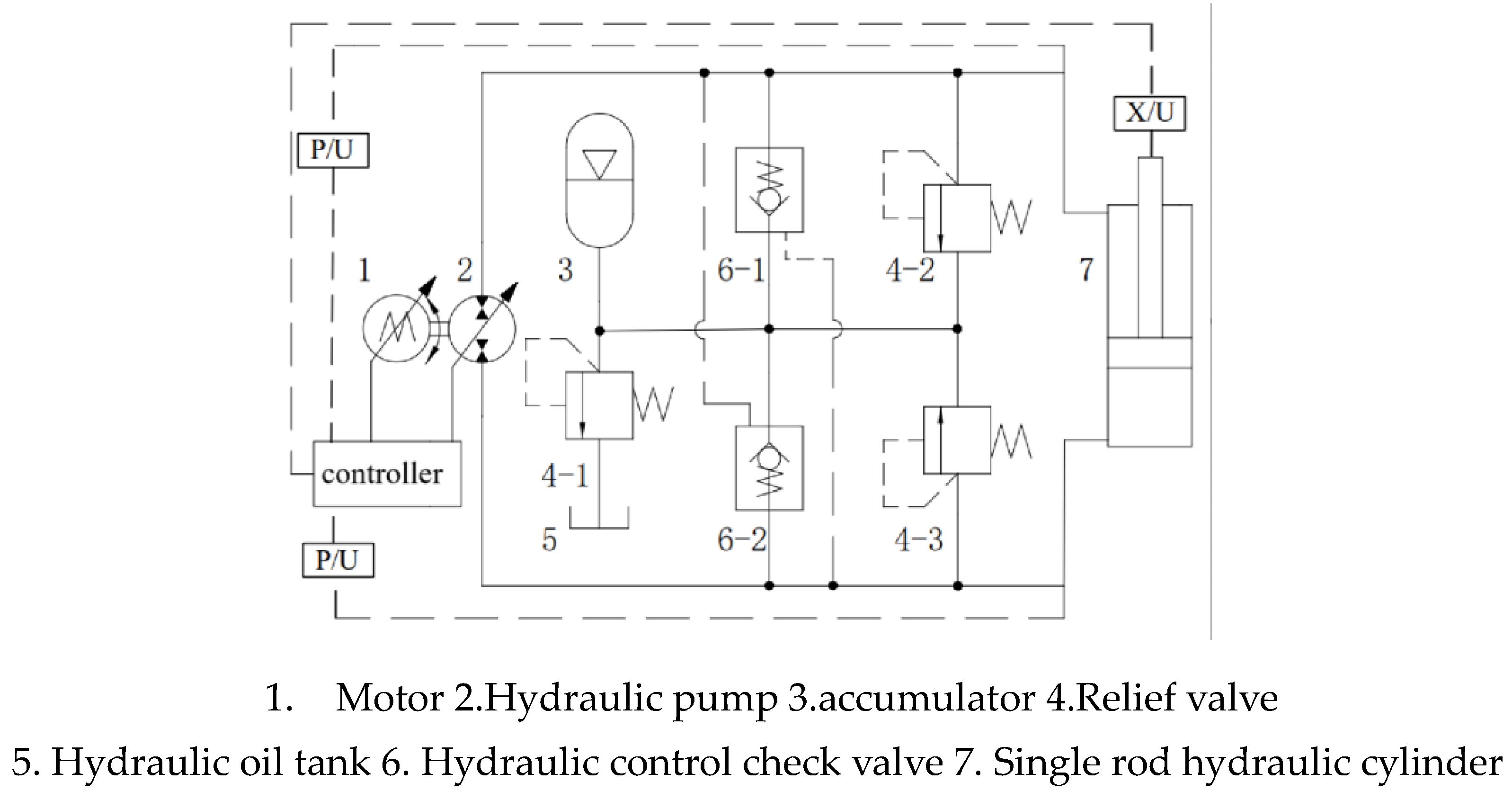
Figure 2.
Control principle of variable speed and constant displacement.
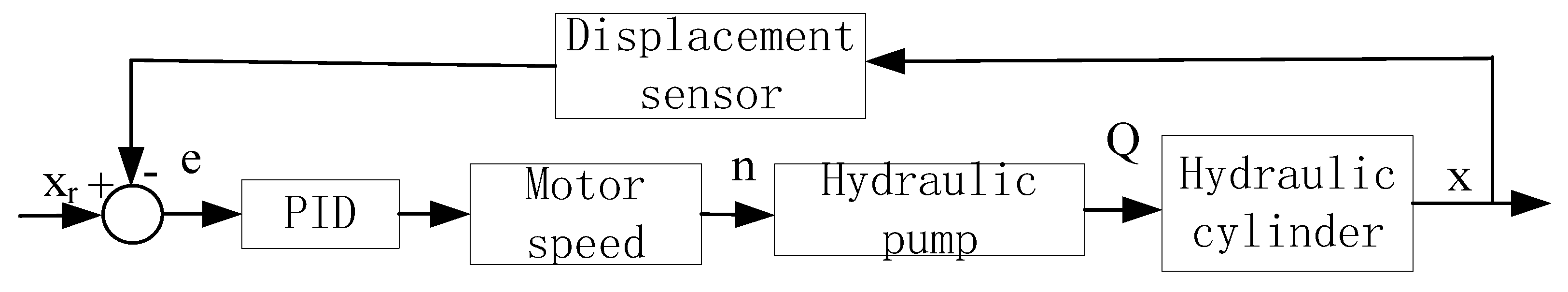
Figure 3.
Compound control principle.
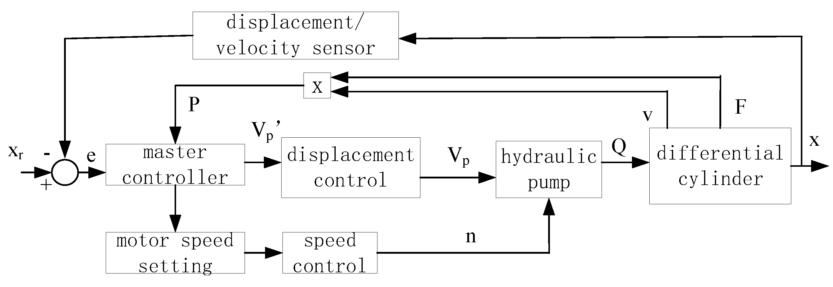
Figure 4.
Energy consumption experiment of variable displacement hydraulic pump driven by variable speed motor.
Figure 4.
Energy consumption experiment of variable displacement hydraulic pump driven by variable speed motor.
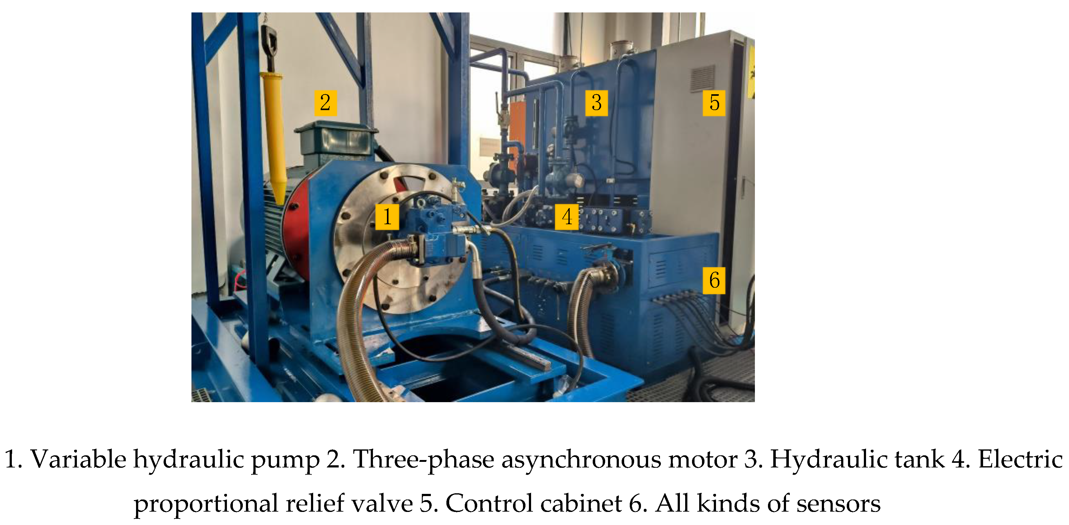
Figure 5.
Actual picture of the control part of the experimental platform.
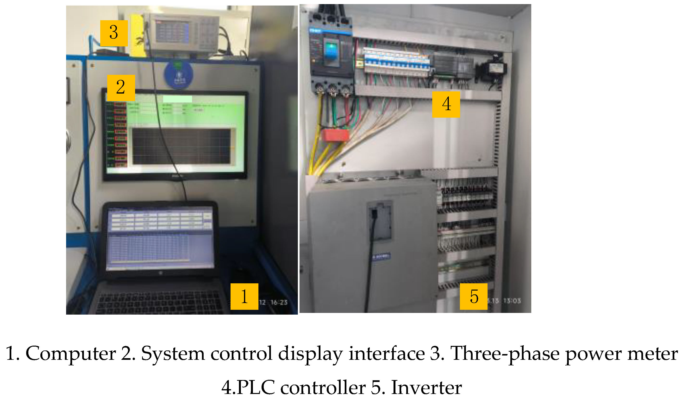
Figure 6.
(a) P=8MPa,Q=85L/min efficiency curve. (b) Efficiency changes under different combination of speed and displacement.
Figure 6.
(a) P=8MPa,Q=85L/min efficiency curve. (b) Efficiency changes under different combination of speed and displacement.
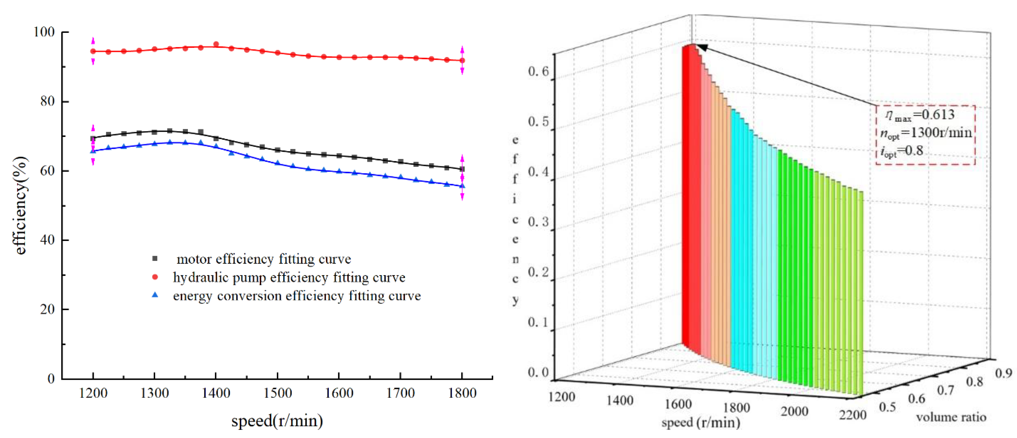
Figure 7.
(a) P=10MPa, Q=85L/min efficiency curve. (b) Efficiency changes under different combination of speed and distance.
Figure 7.
(a) P=10MPa, Q=85L/min efficiency curve. (b) Efficiency changes under different combination of speed and distance.
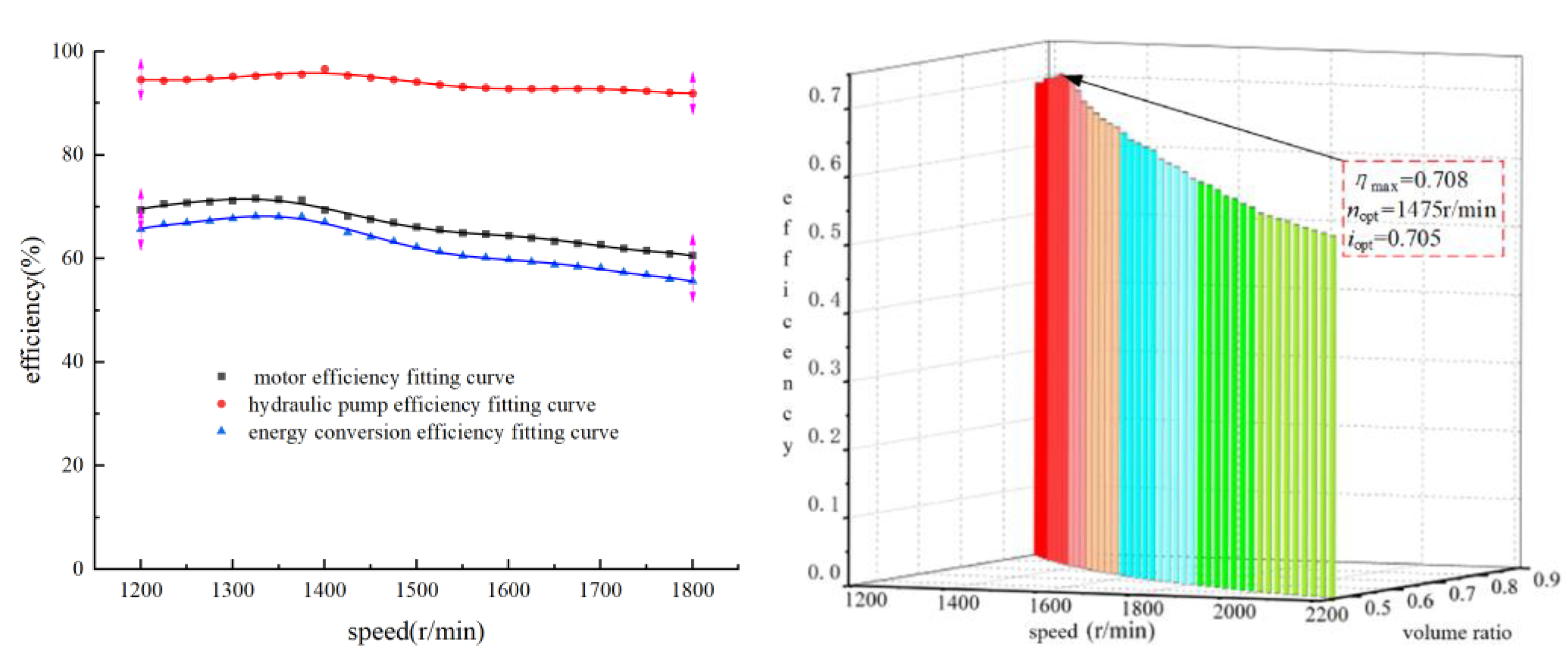
Figure 8.
(a) P=12MPa,Q=85L/min efficiency curve. (b) Efficiency changes under different different combination of speed and distance.
Figure 8.
(a) P=12MPa,Q=85L/min efficiency curve. (b) Efficiency changes under different different combination of speed and distance.
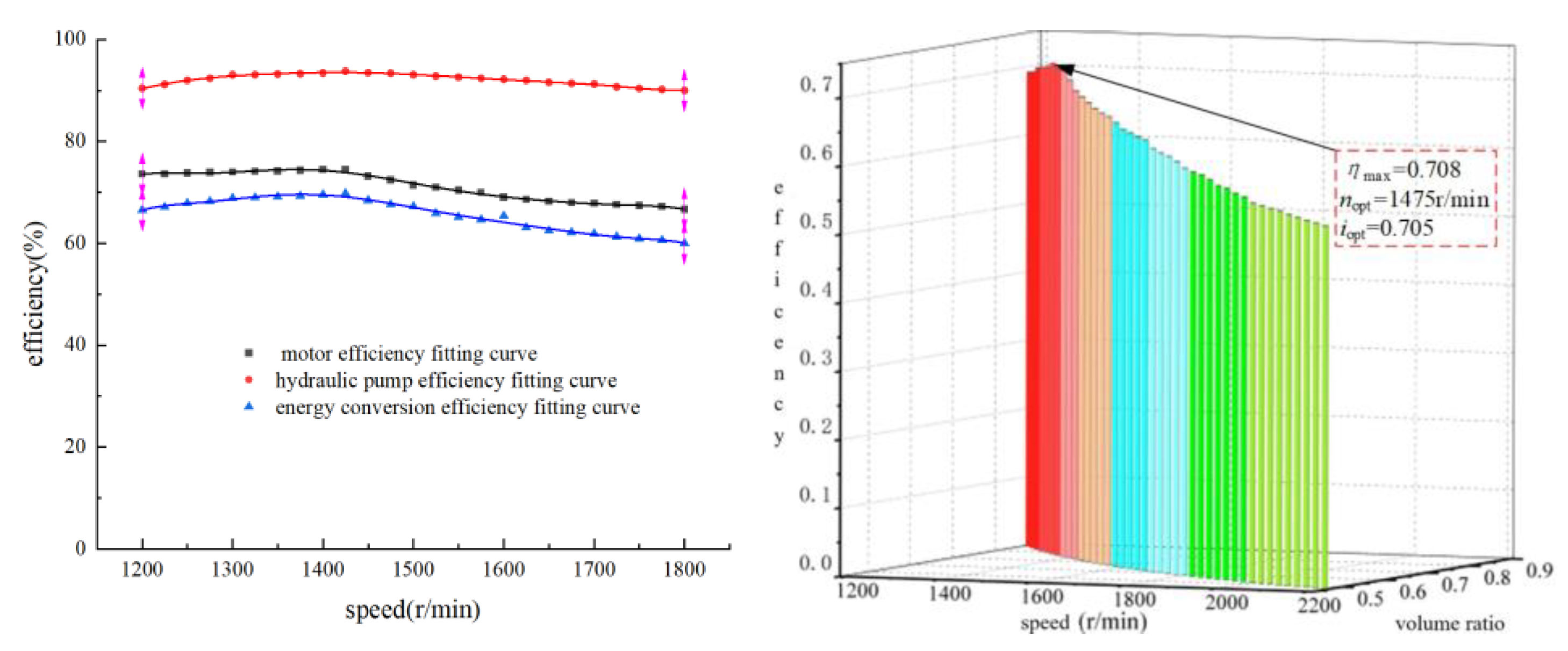
Figure 9.
(a) P=14MPa,Q=85L/min efficiency curve. (b) Efficiency changes under different different combination of speed and distance.
Figure 9.
(a) P=14MPa,Q=85L/min efficiency curve. (b) Efficiency changes under different different combination of speed and distance.
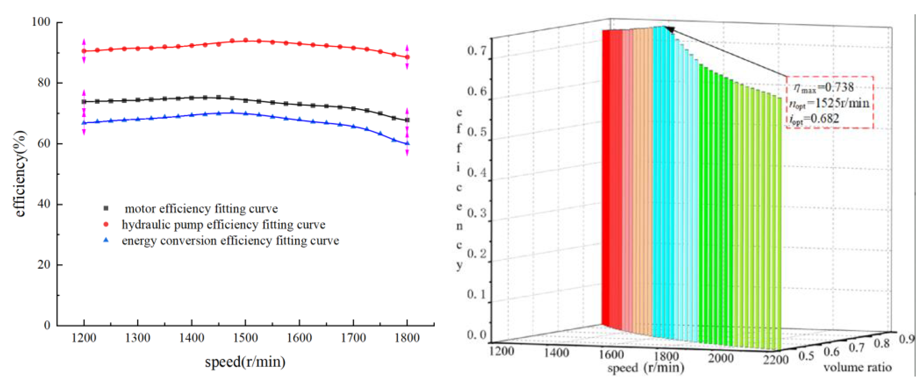
Figure 10.
(a)P=16MPa,Q=85L/min efficiency curve. (b) Efficiency changes under different different combination of speed and distance.
Figure 10.
(a)P=16MPa,Q=85L/min efficiency curve. (b) Efficiency changes under different different combination of speed and distance.

Figure 11.
Optimal speed rule of different load power.
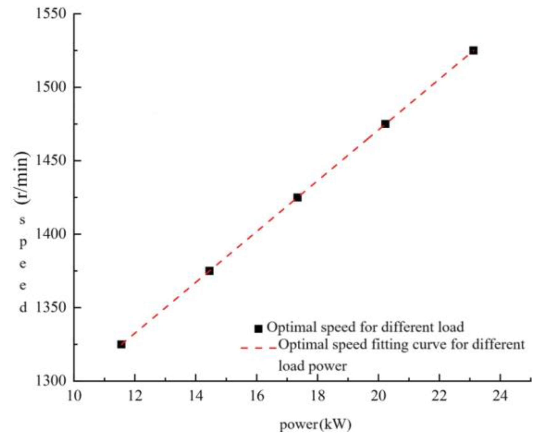
Figure 12.
Combined pump control system of excavator motor arm.
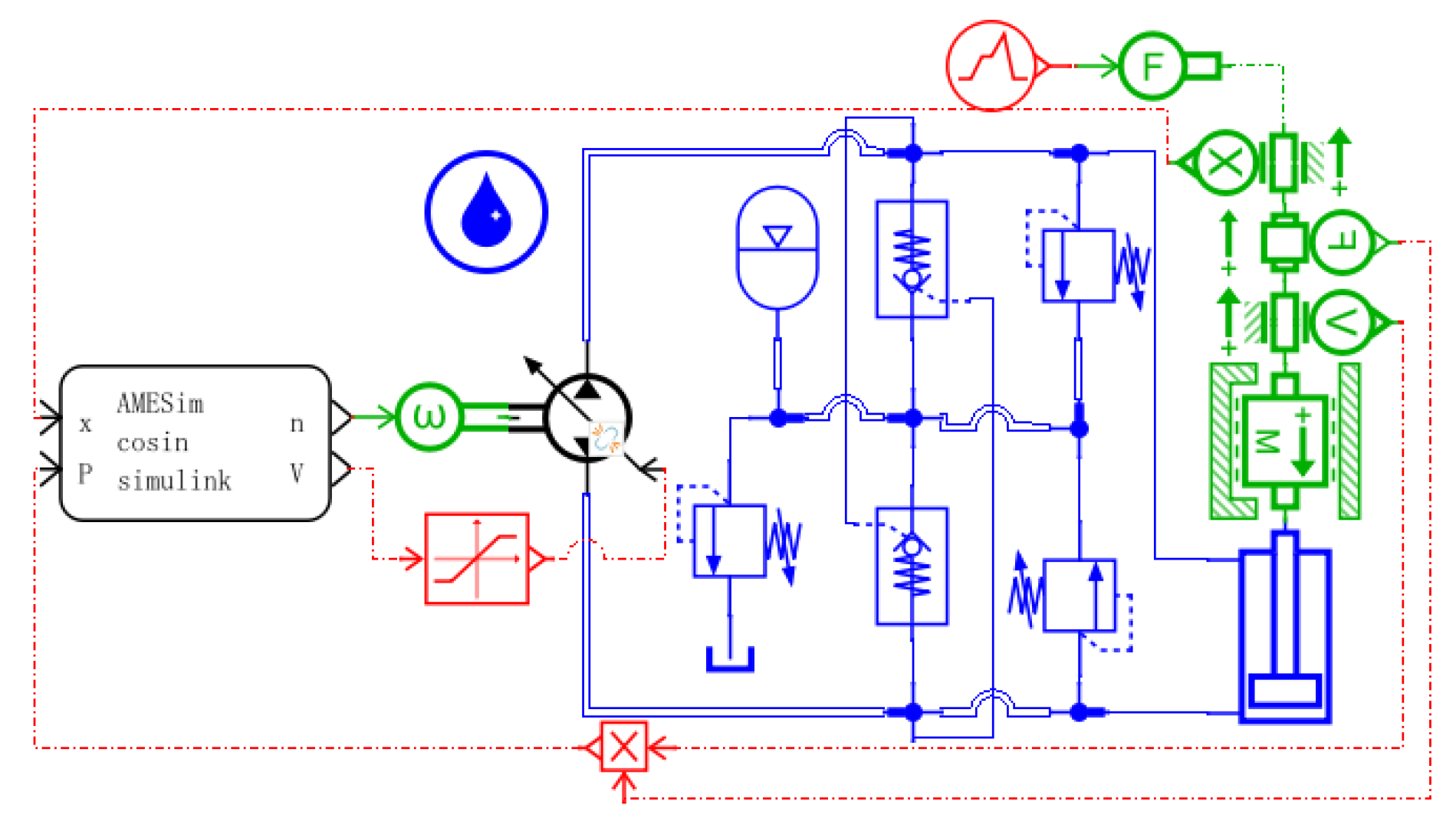
Figure 13.
Simulation model of hydraulic system of boom compound pump control cylinder.

Figure 14.
Control model of composite pump control system.
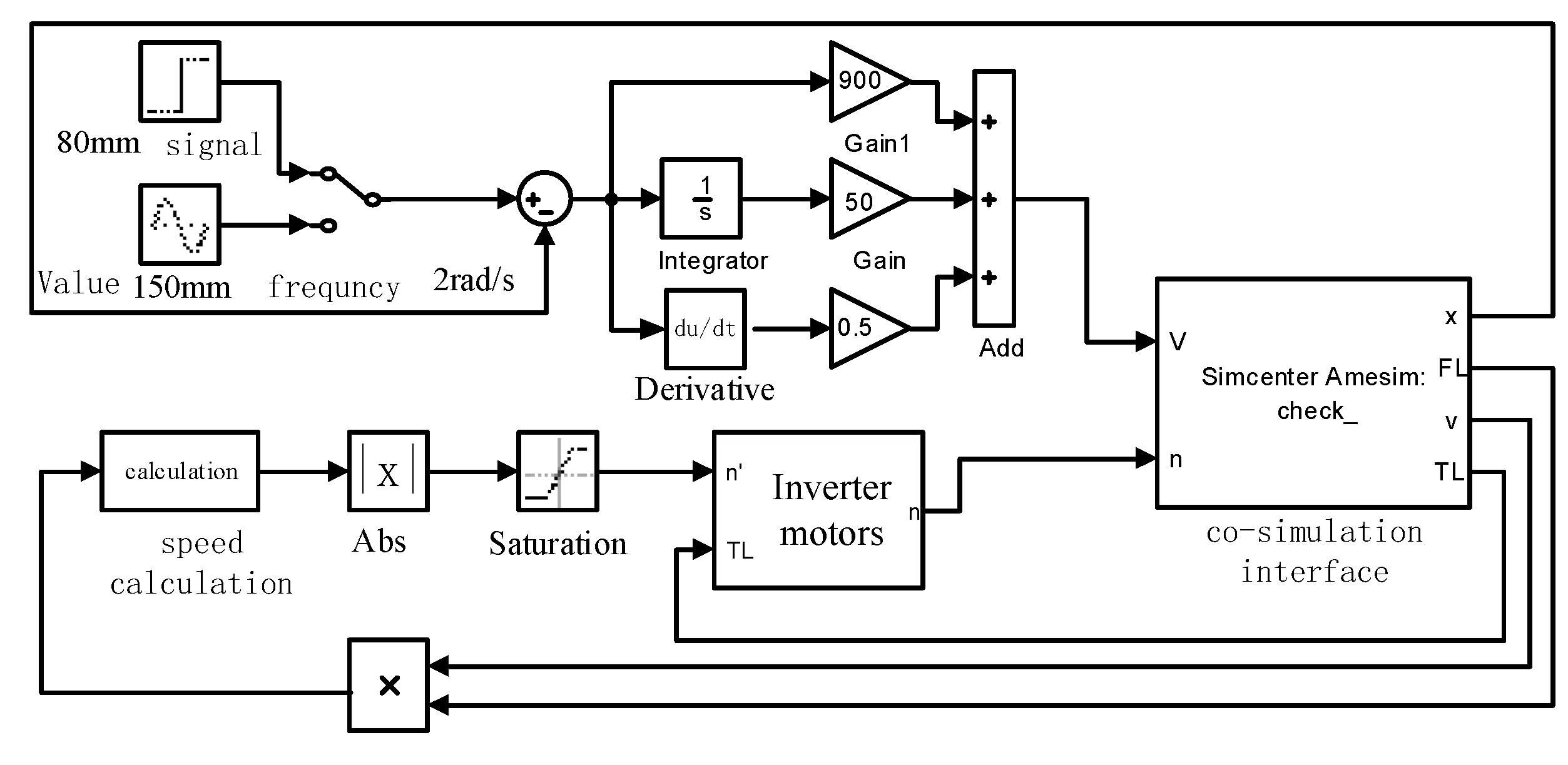
Figure 15.
Comparison of boom displacement of three control modes.
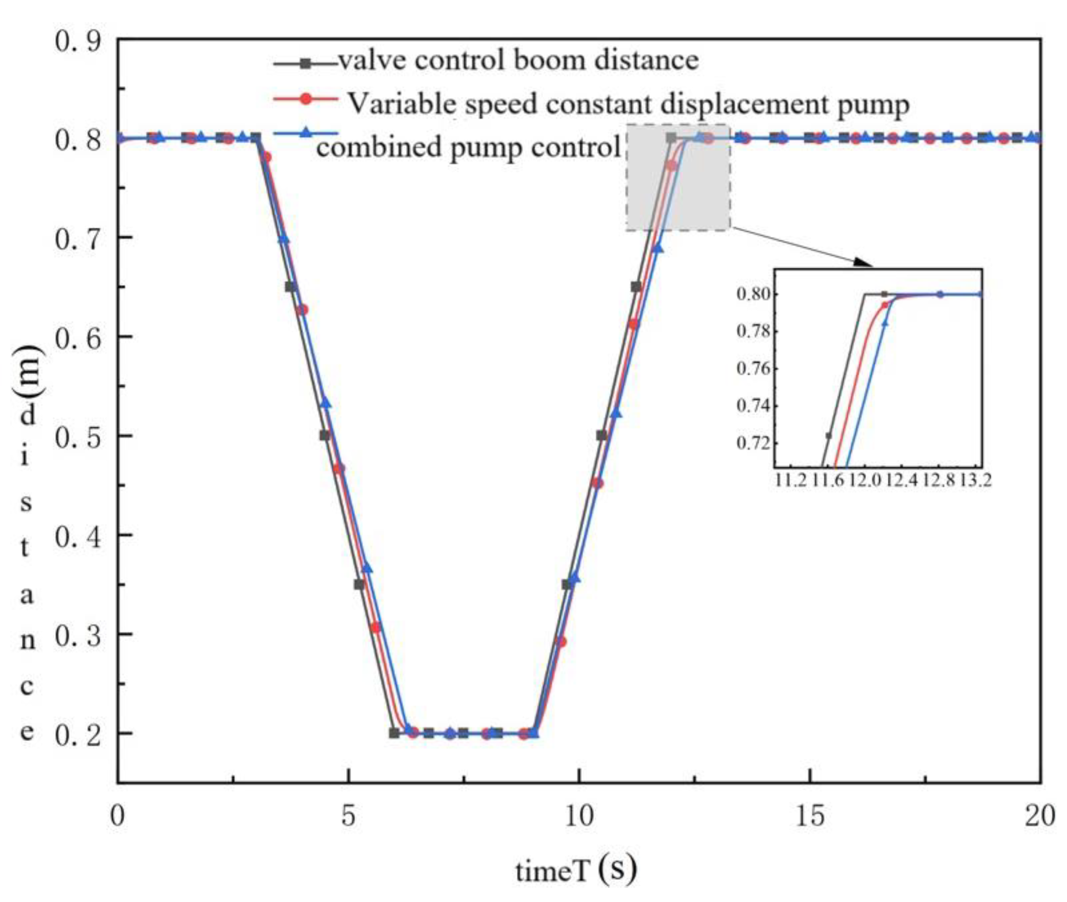
Figure 16.
Comparison of energy consumption of the three control modes.
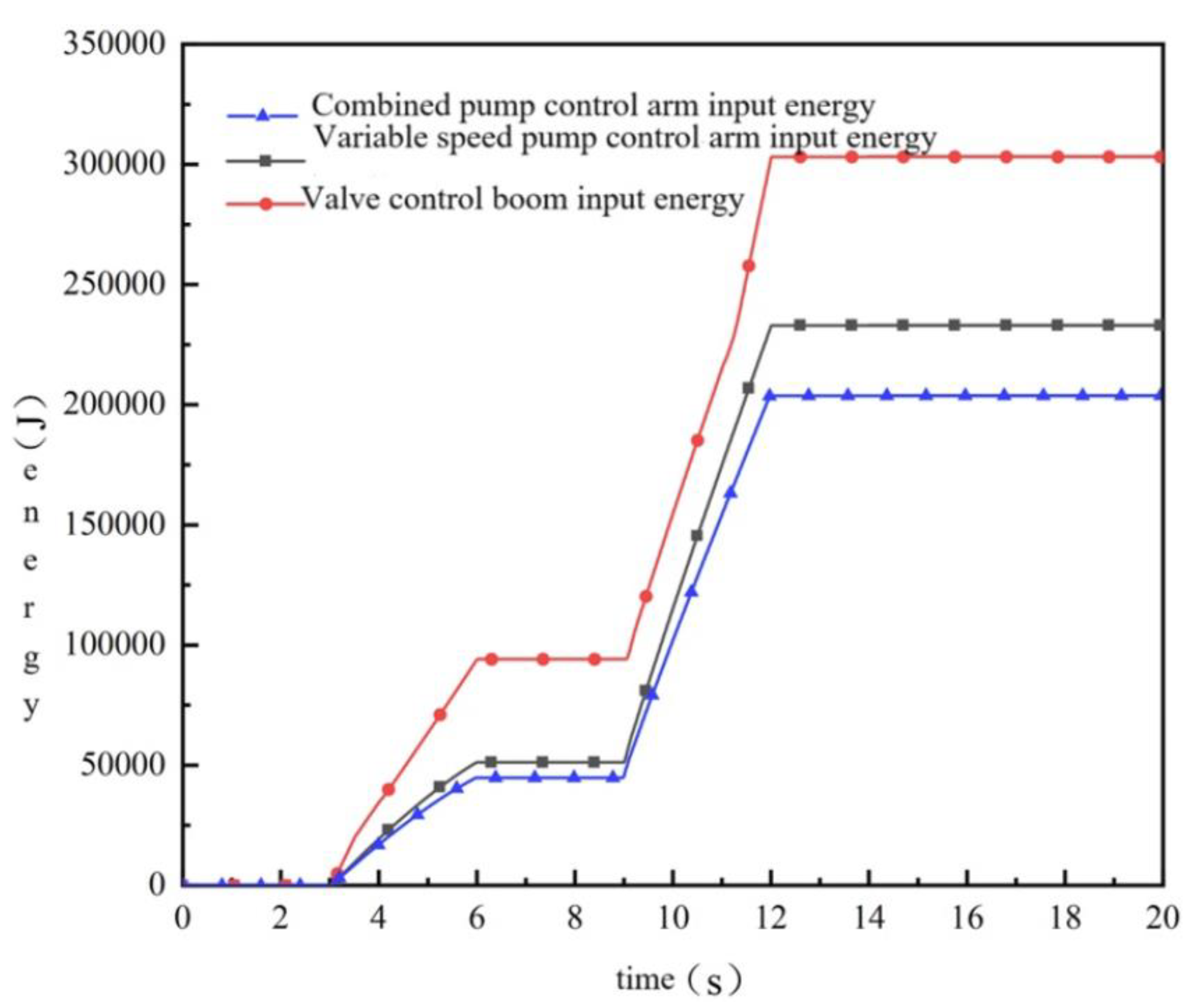

Table 1.
The main parameters of the experimental platform.
| name | item | quantitative value |
| three-phase power meter | voltage | 10.0-500.0V |
| current | 0.03-40A | |
| frequency | 45-65 Hz | |
| three-phase induction motor | rated power | 110kW |
| rated voltage | 380V | |
| rated current | 195A | |
| rated speed | 2980r/min | |
| frequency changer | input capacitance | 160kVA |
| speed stability accuracy | ±0.5% | |
| torque control accuracy | ±5% | |
| hydraulic pump | maximum displacement | 85ml/r |
| speed range | 500-3000r/min | |
| maximum pressure | 35MPa | |
| torque speedsensor | power source | ±24V |
| torque signal | 5-15khz | |
| speed range | 0-3000r/min | |
| frequency response | 3ms | |
| overflow valve | diameter | 30mm |
| maximum working pressure | 31.5MPa | |
| maximum flow rate | 650L/min |
Table 2.
Optimal speed rule of different load power.
| load power(kW) | optimum speed (r/min) |
efficiency (%) |
| 11.56 | 1325 | 61.05 |
| 14.45 | 1375 | 68.12 |
| 17.34 | 1425 | 69.78 |
| 20.23 | 1475 | 70.51 |
| 23.12 | 1525 | 73.82 |
Table 3.
Main parameters of pump control system.
| item | numerical value |
| variable pump maximum displacement(ml/r) | 25 |
| rated torque of the motor( Nm) | 80 |
| rated motor speed( r/min) | 2000 |
| rated power of motor( kW) | 15 |
| hydraulic cylinder bore (mm) | 40 |
| hydraulic cylinder rod diameter (mm) | 25 |
| accumulator volume( L) | 6 |
| accumulator precharge pressure( bar) | 15 |
Disclaimer/Publisher’s Note: The statements, opinions and data contained in all publications are solely those of the individual author(s) and contributor(s) and not of MDPI and/or the editor(s). MDPI and/or the editor(s) disclaim responsibility for any injury to people or property resulting from any ideas, methods, instructions or products referred to in the content. |
© 2024 by the authors. Licensee MDPI, Basel, Switzerland. This article is an open access article distributed under the terms and conditions of the Creative Commons Attribution (CC BY) license (http://creativecommons.org/licenses/by/4.0/).
Copyright: This open access article is published under a Creative Commons CC BY 4.0 license, which permit the free download, distribution, and reuse, provided that the author and preprint are cited in any reuse.


