
Submitted:
21 April 2025
Posted:
22 April 2025
You are already at the latest version
Abstract
To address the problems of limited basic tissue loops and insufficient control of floating-length threads in WCAD and other programs, the YWCAD system for fabric tissue design was developed by adopting the directional and non-directional dual-path generating mechanism of yarn, the multi-structural generating mode of tissues, and the algorithm of preferential selection of floating-length threads. The directional mode of yarn generates the target yarn based on the fractional structure, and the non-directional mode randomly combines the decomposition conditions through the algorithm to realize the exponential expansion of yarn morphology; the weave generates and builds the single/multi-structure dual mode, with the single structure supporting the manual or random setting of the number of flights, and the multi-structure integrating the three elements of yarn selection, alignment ratio and number of flights to break through the technological bottleneck of the poor diversity of the weave; and at the same time, it introduces three-fold optimization of the maximal floating length, the average floating length and the uniformity of the distribution of the weave points. Simultaneously, the maximum floating length, average floating length, and uniformity of tissue point distribution are introduced as triple optimization indexes, and the intelligent screening algorithm solves production problems such as fabric arching and uneven tension. Experiments show that this system significantly improves fabric tissue diversity while guaranteeing the rationality of the process, and provides a new intelligent solution for the digital generation of fabric tissue.
Keywords:
digitalization
; intelligence
; CAD
; fabric weave
1. Introduction
The author's research laboratory has developed the innovative design program WWCAD for woven fabric weaves in the previous period and focused on the development of two weave design modules with different technological approaches: PWCAD and WWCAD. The PWCAD module is based on graphic processing technology, which employs embellishing, dragging, enlarging, duplicating, flipping, rotating, superimposing, and stretching of the given basic weave map symbols, PWCAD module is also based on graphic processing technology, which greatly enriches the effect of weave change by embellishing, dragging, enlarging, copying, flipping, rotating, overlaying, extending, and graphic combination of the given basic weave symbols. These two modules greatly improve the efficiency and diversity of fabric design, but both are based on the graphic or yarn adjustment changes to the basic weave to design the weave; that is to say, the first directional design of the basic weave, which will lead to the complexity of the basic weave of the changes in the design of the size of the loop and other aspects of the relatively large limitations, and may also lead to changes or reweave of the weave in the length of the floating length of the line length, the distribution of the weave of point. It may also lead to the change or reweave of the weave in the floating length of the line length, the distribution of weave points, and other aspects of the uniformity cannot be effectively optimized control, which will lead to the weaving of large differences in weaving shrinkage, fabric texture distribution, and other problems.
At present, most of the fabric design CAD software in the weave design module is basically a direct drawing of the weave, simple digital methods to generate the weave, image analysis to generate the weave of the coming samples, or through the machine diagram of the three diagrams of the interrelationship between the generation of the weave, the fabric weave of the design of the software is basically based on human orientation design, lack of flexibility and freedom, when the need to improve or innovative design can often be solved using mouse clicks or simple digital technology. and freedom, when need to improve or innovative design, often only through the mouse click or simple digital technology to solve, which is not only time-consuming and laborious, and inefficient, the design of the composition is also more limited.
To this end, this paper further develops the YWCAD functional module from yarn digital design to fabric weave design by comprehensively applying Visual Basic 6.0, Python and other programming languages.
2. Principles of Fabric Weave Composition Based on Weave Point Distribution Characterization of Yarns
According to the theory of fabric histology, when naming the plain and plain change weave, twill and twill change weave, it usually adopts a fractional formula consisting of the numerator and denominator to express it simply, in which the value on the numerator indicates the number of consecutive warp weave dots, and the value of the denominator indicates the number of consecutive weft weave dots. Taking the weave shown in Figure 1 as an example, according to the interpretation of the warp yarn, the weave can be expressed by↗ fractional formula. Along the longitudinal direction from left to right root by root analysis of the distribution of warp and weft weave points on each warp yarn (in order from bottom to top), the warp (or weft) weave points with the warp (or weft) are simply expressed; the number of numbers indicates the number of consecutive points of the same weave point symbols, n indicates the total number of segments of a warp yarn spaced apart by the warp and weft weave points, n j and n w, respectively, indicate that n is the number of segments composed of consecutive warp weave points and the number of segments consecutively composed of consecutive weft weave points, the number of zones composed of continuous latitudinal weave points zones. Similarly, it is possible to interpret the distribution of warp and weft weave points on each weft yarn individually along the transverse direction, which will not be repeated here.
1. by the number of consecutive warp weave point segments and the number of consecutive weft weave point segments are equal, can be expressed using the subformula, the subformula in j i and w i respectively represents the number of consecutive warp weave point segments and the number of consecutive weft weave point segments. The number of consecutive identical weave point segments of the selected yarn is increased by one when the segment is split into two parts in the histogram for this attribute weave point segment.
2. Total number of warp weave points on yarn , total number of weft weave points , number of weave point distribution cycles of yarn . If , the yarn shows the same effect as warp and weft, , showing the effect of warp, , showing the effect of weft.
3. All values of and are greater than or equal to 1, where the maximum value is the floating length value of the longest floating length line on the yarn. If the fractional representation of the warp yarn, the maximum value appears in the numerator then, the longest floating length line is presented as the front of the fabric warp floating length line, and appears in the denominator then, the longest floating length line is presented as the reverse side of the fabric warp floating length line; if the fractional representation of the weft yarn, the maximum value appears in the numerator , then the longest floating length line is presented as the reverse side of the fabric latitude floating length line, appears in the denominator , and the longest floating length line is presented as the front side of the fabric latitude floating length line.
4. Let the average floating length value of the yarn be T. According to the concept of average floating length, it is known that .
5. The weave shown in Figure 1(a) is a regular weave that adopts the same fractional formula to express the distribution of warp and weft weave points of yarns arranged warp (or weft) by warp (or weft) yarns individually according to equal fly values (Sj or Sw). The weave shown in Figure 1(b) is obtained by adopting the same fractions of the warp yarns of the weave shown in (a) and arranging each warp yarn in turn according to the warp direction fly number S(j) in order of 2, 3, 2, 3, 2, 3, 2, 3, 2, 3, 2, 3, 2, 3, 2, and 3 in order of regularity.
6, Figure 2 shows five weave charts are respectively composed of different sub-forms of the right diagonal, , are the same side of the weave. Set to take 2 vertical grid and 2 horizontal grid composed of 2× 2-square and 4 vertical grid and 4 horizontal grid composed of 4× 4-square two kinds of test area, respectively, test the five weaves in the test area of the warp and weft weave point number of the situation, and another set of the test area of the warp weave point number of Q j, the number of weft weave point number of Q w, the results are shown in Table 1. It can be found that the fewer the number of different conditions of Qj and Qw values, the more uniform the distribution of weave points; the smaller the selected test area, the more the uniformity of the distribution of weave points that can be detected; among the five weaves, the advantages and disadvantages of the uniformity of the distribution of weave points are in the order of (a), (b), (c), (d), and (e).
3. Technical Program of the YWCAD Module
3.1. Basic Architecture of the YWCAD Module
According to the above analysis, the basic scheme of YWCAD design weave can be constructed: by decomposing two given positive integer values into small positive integer values, and using them as the numerator and denominator arrays of the fractal equation, the digitized yarn characterized by the distribution of warp and weft weave points of can be generated; by arranging the digitized yarns with directional or random selection in a directional or non-directional way, the fabric weave can be generated; by setting the size and quantity of the decomposition values, the problem of floating length and average floating length and yarn screening can be solved; by interpreting and analyzing the size and quantity of the decomposition values of another system of yarn, the problem of limiting the floating length and average floating length and yarn screening can be solved. By setting the size and number of decomposition values, the problem of limiting the floating length and average floating length of digitized yarns and yarn screening is solved; by interpreting and analyzing the size and number of decomposition values of yarns from another system in fractions, the problem of limiting the floating length and average floating length of yarns from another system and weave screening is solved; and by selecting the test area and establishing the filtering conditions, the problem of screening the weave that conforms to the requirement of uniformity of weave point distribution is solved. The architecture of the YWCAD module is shown in Figure 3.
3.2. Solution for YWCAD Module
3.2.1. Numerical Decomposition Constructive Fractal Based Yarn Digital Design Solution
For the directional digital design of yarn, you can directly input the decomposition value of the numerator j1, j2, j3, ... and the decomposition value of the denominator w1, w2, w3, ... (the number of decomposition values of the numerator and denominator should be equal), choose to design the warp or weft, and then, the system generates the corresponding yarns according to the characteristics of the distribution of warp and weft weave points. corresponding yarns.
The following methods can be used for the nondirectional digital design of yarns.
1. Assign the following positive integer values: the total value of the numerator A, the total value of the denominator B and the number of decompositions n. Where .
2, by automatically decomposing the A (or B) value, the A (or B) value is randomly decomposed into n or n + 1 values of the positive integer set M a (or M b), M a (or M b) can theoretically exist in an infinite number of, and with the increase of A (or B) value, the decomposition of the result of the number of the more.
3. One Ma and one M(b) are selected by human selection or randomly by computer.
4. The numerical orderings of Ma and Mb are randomly generated by a computer, and theoretically, there exists an infinite number of numerical orderings for both Ma and Mb.
5. An Ma arrangement and Mb arrangement are randomly selected by human selection or by computer.
6, M a and M b as the numerator and denominator, respectively, can be generated by the distribution of the warp and weft weave points composed of yarn. When M a and M b are each composed of n values, through the warp start or weft start option to determine by the numerator (warp weave point) and by the denominator (weft weave point) to start laying the weave point; when M a has n + 1 values, M b n values, the system automatically by the molecule (warp weave point) to start laying the weave point; when M a has n values, M b is n + 1 values, the system automatically starts laying out weave points from the denominator (latitude weave points).
7, the establishment of a digital yarn database, according to the establishment of different categories and needs of the sub-base, is generated by the digital yarn that can be instantly deposited.
3.2.2. Digital Yarn-Based Fabric Weave Design Solutions
After generating digitized yarns or pulling them out of the yarn bank and determining their application system (warp or weft), they can be digitally arranged to generate fabric weave.
1. If the designed fabric weave consists of a single digitized yarn arrangement, the fly value Sj (or Sw) can be entered to generate the weave in a directional manner, or the weave can be randomly generated by the computer. When digitized yarns are used as warp yarns, the fly value of the yarns is limited by the number of healds for dobby looms or the number of patterned needles for Jacquard looms, but the random arrangement of the yarns is not limited; thus, the theoretically unlimited number of warp loops of the weave. When digitized yarns are used as weft yarns, the choice of the R-value of the digitized yarns is limited by the number of healds for dobby looms or the number of patterned needles for Jacquard looms, but the random arrangement of the yarns is not limited, and thus the theoretically unlimited number of weft cycles of the weave. Therefore, the number of organized weft loops is theoretically unlimited.
2) If the designed fabric weave consists of different digitized yarn arrangements, when the digitized yarn is used as warp yarn, the number of digitized yarns quoted or called out is limited by the number of healds used for dobby looms or the number of needles in the pattern of Jacquard looms, and the arrangement of the same yarn is unrestricted. When the digitized yarn is used as weft yarn, the selection of digitized yarns is limited by the number of healds used for dobby looms or the number of needles in the pattern of Jacquard looms, but the number of digitized yarns quoted or called out is not limited, and their arrangement is unrestricted.
3.2.3. Floating Length Line and Average Floating Length Detection and Preferred Solution for Digitized Yarns
1, in the yarn digital design link to add a maximum floating length parameter setting, that is, we set the maximum allowable value in the sub-equation , through the system run to make the A and B values of the decomposition of the value of≤ , so that you can ensure that the yarn's maximum floating length of the line is in the permissible range.
2, the creation of warp and weft yarn sub-modules of interpretation and screening of the composition of the sub-module, in the selection of digital yarn as a system of yarn (warp or weft) and run the digital arrangement to complete the fabric weave design, run this sub-module, set the maximum allowable value of the sub-module , to be able to interpret the sub-module of another system of yarn (weft or warp), and automatically screen out unqualified weaves, to ensure that the maximum of the direction of the fabric weave of another system of floating long lines within the allowable range. The float lengths in the direction of the other fabric weave system were within the permissible limits.
3, the creation of the calculation of warp and weft yarn average floating length and extreme value ratio sub-module, in the run different digital yarn arrangements to generate fabric weave, set the selection of digital yarn average floating length difference range, that is, the weave of the maximum average floating length of yarn and the minimum average floating length of the of ratio, run this sub-module, calculate the average floating length of yarns one by one, extract the maximum and minimum values, and calculate the ratio of the two, automatically screen out the It will automatically screen out the non-compliant weaves and ensure that the variation in the average floating length of the fabric weaves is within the permissible range.
3.2.4. Detection and Preference of Solutions for the Number of Points of the Warp and Weft Weave and Their Distribution
Create the detection function submodule, establish 2× 2, 2× 3, 3× 2, 3× 3, ..., and other detection areas; by selecting the detection area, the Q j, Q w value does not allow the appearance of the conditions, and can be filtered and screened for the design of the fabric weave. Figure 4 shows the digital design of the weave, for example, when selecting 2× 2 detection area, set does not allow the appearance of Q j= 4 (Q w = 0) or Q j= 0 (Q w = 4) conditions, you can find that the weave does not meet the conditions, it is filtered out of the filtering; if you select 2× 3 or 3× 2 detection area, when set does not allow the appearance of Q j= 6 (Q w = 0) or Q j= 0 (Q (w) = 6) condition, the weave is still screened out by the filter; if 3× 3 detection area is selected, when the setting does not allow the occurrence of Qj = 9 (Qw = 0) or Qj= 0 (Qw = 9) condition, the weave meets the requirements and is selected.
4. YWCAD Module Operation and Validation
4.1. Yarn Digital Generation
Based on the basic principle of the fractional characterization of yarns, YWCAD digitally generates yarns by both directional and nondirectional means.
4.1.1. Directional Yarn Formation
Users first need to select the generation method in the Directed Generation window, and then enter the numerator and denominator in turn. The numerator and denominator are the elements that characterize the fractional structure of the yarn, which represent the warp and weft weave points, respectively, and then click on Generate Yarn to generate yarns based on the time-sharing structure automatically.
4.1.2. Non-Directional Yarn Formation
As shown in Figure 6, after inputting the number of integers to be decomposed, the number of decompositions, and the maximum value of decomposition, all possible arrangements are generated automatically; that is, when 20 is decomposed into five integers not exceeding 7, there are a total of 32 arrangements, as shown in Figure 6(a). Select "2 2 4 6 6" and "2 2 4 5 7" as the numerator and denominator of the two arrangements of the array, the arrangement of its reweave, reweave of the arrangement and then cross the generation of new arrangements, a total of 30× 60× 2, that is, 3600 kinds of arrangements, as shown in Figure 6 (b). A total of 30 60 2, that is, 3600 arrangements, are shown in Figure 6(b), from which one arrangement” is randomly selected and the corresponding yarn is generated, as shown in Figure 6(c).
4.2. Digital Generation of Weaves
YWCAD digitally generates weaves by calling yarns from a database and subsequently processing them to generate weaves. There are two types of generation: single-structure generation and multistructure generation, each of which has two types of generation, directional and nondirectional, and its arrangement also includes two types of directional and nondirectional arrangements.
4.2.1. Single-Structure Generation Weave
The directional generation of weave has two modes: fixed and variable. The fixed fly count is the automatic generation of all weaves by inputting the fly count after setting the number of latitude and longitude cycles, whereas variable fly count is the generation of weaves one by one after inputting the fly count one by one.
(1) Organisation of weaves
As shown in Figure 7(a), a yarn with the arrangement of " " is selected from the yarn database, and the fixed fly count generation and the variable fly count generation are performed on it respectively, which present two completely different effects. Figure 7(b) generates the subsequent weave with the fly number "3"; Figure 7(c) is the operation page for selecting the weave with the variable fly number, entering different fly numbers one by one and generating the corresponding yarns; Figure 7(d) demonstrates that the fly number of the second yarn is 2, and Figure 7(e) is the fly number of the second yarn with the fly number "2 4 1 5 2 1 2 3 5.” Figure 7(e) shows the generation of all weaves according to fly number "2 4 1 5 2 1 2 1 2.”
(2) Nondirected student weaves
There are two methods of non-directional generation of weaves from a single structure: random fly count generation and yarn reconstruction method. Random fly count is based on the first yarn, through the algorithm and the Rnd function to generate the random fly count at the same time to generate the corresponding weaves, and the yarn reconstruction method is based on the two arrays of the first yarn, in all the possibilities of its random permutation combinations according to the number of warping cycles to randomly select different combinations and generate the corresponding yarns that finally compose the weave.
As shown in Figure 8(a), a yarn " " is selected from the yarn database as the base weave, and after the user selects the number of warp and weft cycles as 20, and then clicks on the generate control, the system uses the random function to automatically calculate and generate the complete weave based on the first warp yarn, and the generation result is shown in Figure 8(b), and the number of flights of the weave are 8,14 2,11,13,6,11,8,10,1,11,17,15,4,12,10,1,9,19.
As shown in Figure 9(a), the total number of decompositions is set to 15, which is decomposed into four integers not exceeding 6, with a total of 11 arrangements, from which two sets of "2 3 4 6" and "3 3 4 5" are selected for arrangement and combination, and there are a total of 288 different combination methods, and the number of cycles is set to 18, which automatically picks 18 out of the 288 arrangements and generates the corresponding yarns. A total of 288 combinations were used. After setting the number of warp cycles to 18, 18 types of yarns were automatically selected from the 288 combinations and corresponding yarns were generated. These yarns were combined to form the weave, as shown in Figure 9(b) as an example.
4.2.2. Multi-Structure Generation Weave
For a multistructure generation weave, the first two yarns need to be called from the database, as shown in Figure 10.
Figure 11 shows an example of a directional generation arrangement and weave after directional selection. Yarn A ( ) as shown in Figure 11(a) and B ( ) as shown in Figure 11(b) are chosen as the base yarns, which are oriented according to the 10:10 arrangement ratio, and at the same time, oriented generation, where yarn A is generated in accordance with the number of flights +1, and yarn B is generated in accordance with the number of flights -1, constituting an weave with a primer effect, as shown in Figure 11(c). .
Figure 12 shows an example of non-directional selection followed by directional generation of arrangement ratio and weave, randomly selecting yarns A" " from the database as shown in Figure 12 (a), and B" " as shown in Figure 12 (b), in accordance with the 1:1 arrangement ratio of the columns, and both in accordance with the fly number 1 of the regularity to generate subsequent yarns to form a complete weave, as shown in Figure 12(c).
Figure 2, Figure 3, Figure 4, Figure 5, Figure 6, Figure 7, Figure 8, Figure 9, Figure 10, Figure 11, Figure 12, Figure 13, Figure 14, Figure 15 and Figure 16 shows an example of nondirectional alignment and generation after the nondirectional selection of yarns. Yarn A " " is randomly selected as shown in Figure 13(a) and yarn B " " is shown in Figure 13(b), and the algorithm randomly generates the alignment ratio " 2:5:4:2:4:3", yarn A is arranged according to the fly count of " 2 1 6 5 2 1 1 3 7 4" and yarn B is arranged according to the fly count of "4 2 3 1 9 8 2 7 2" as shown in Figure 13(c).
Figure 14 shows an example of nondirected selection followed by directed and nondirected generation. Yarn A " " as shown in Figure 14(a) and yarn B " " as shown in Figure 14(b) are randomly called from the database and the fixed arrangement ratio is entered as follows "2:2", yarn A is arranged according to the fly number "3 2 5 6 1 2 4 1 5,” and yarn B is arranged according to the fly number "6 1 3 5 2 7 1 3 9,” which generates an intricate and complex weave, with a unique crepe effect. The resulting weave is intricate and exhibits a unique creep effect, as shown in Figure 14(c).
4.3. Digital Filtering and Optimization of the Weave
4.3.1. Maximum Float Length Screening
As shown in Figure 15(a), the randomly generated weave floating length line is too long, which leads to uneven fabric surfaces when weaving on the machine. At the same time, the strength of the dense weft floating length line is weak, so it is easy to break the yarns when weaving, resulting in uneven tension, uneven weaving, and other symptoms, which not only affect the efficiency, but also affect the aesthetics and completeness of the fabric. Therefore, as shown in Figure 15(b), the maximum floating length line is set to 3, and the combination generated after screening is shown in Figure 15(c), which is neat and beautiful, with an even distribution of weave points, and also with a unique pattern, which takes into account both scientific and ornamental aspects.
4.3.2. Mean Float Length Screening
As shown in Figure 16(a), the maximum ratio of the average floating length of the randomly generated weaves is too large, which leads to different interaction forces between different yarns, thus affecting the overall structure and dimensional stability of the fabric and affecting the weaving shrinkage. Therefore, the maximum ratio was set to 2.5, and the ratio of screened weaves was 2. The number of yarn in the weaves was similar and the fabric performance was better. However, it can be noted that the weave shown in Figure 16(a) is only screened for the average floating length, so the maximum floating length is still very long, which affects the coordination and aesthetics of the weave, as shown in Figure 16(b). The weave shown in Figure 16(c) is set to have a maximum floating length of 4, and then constrains the maximum ratio of the average floating length so that it does not exceed 2.5, which generates an weave that is not only innovative, but also meets the needs of actual production and preparation, as shown in Figure 16(c). The generated weave is both innovative and meets the needs of the actual production preparation, as shown in Figure 16(d).
3.3.3. Screening Techniques for Uniformity of Weave Point Distribution
As shown in Figure 17, because the maximum warp float length in the selected warp is three, the maximum retrieval module is set to 3× 3, that is, no Qj=9 (Qw=0) or Qw=9 (Qj=0) is allowed in any 3× 3 region in this weave. At the same time, the weave is also screened by the maximum floating length and average floating length; the maximum floating length is 3, and the average floating length is not more than 2.5. The weave has both randomness and uniqueness in appearance, as well as a unique feel and good physical properties, which can meet the requirements of weaving and realize the perfect unity of production demand and appearance design.
4. Conclusion
YWCAD is based on Visual Basic 6.0 and Access database technology, and realizes the digital design of yarn and weave through directional (user parameter input) and non-directional (algorithmic random generation) dual modes. At the same time, it integrates manual intervention and algorithmic randomness in the logic of single/multiple structure generation, which supports rapid construction of large cycle weave. The optimization module combines the control of float length, distribution uniformity, and other optimization modules that combine floating length control, distribution uniformity, and other indicators to screen solutions and solve weaving process problems. The system overcomes the bottleneck of traditional manual design efficiency and promotes intelligent upgrading of the textile field. However, the function of generating and identifying double-layer weaves has not yet been realized; therefore, it is possible to add a separate identification function to analyze whether the generated weaves are single-layer or double-layer, and then screen and optimize them individually if they are double-layer weaves. At the same time, the current program has a low degree of freedom in the design of some functions and there are some design limitations. If the functions of these two parts are improved, they can generate richer and more diversified weave compositions.
References
- Ala, D. M. & N. Celik (2024) A computer software developed for designing woven patterns and generating machine readable files for sampling looms. JOURNAL OF THE TEXTILE INSTITUTE, 115, 1423-1431.
- Ji, B., J. Zhang, Y. Li & W. Tang (2023) A CAD model retrieval framework based on correlation network and relevance ranking. JOURNAL OF MECHANICAL SCIENCE AND TECHNOLOGY, 37, 1973-1984.
- Jones, B. J. Noeckel, M. Kodnongbua, I. Baran & A. Schulz. 2023. B-rep Matching for Collaborating Across CAD Systems. In ACM TRANSACTIONS ON GRAPHICS. Los Angeles, CA.
- Kahng, A. B. (2023) Machine Learning for CAD/EDA: The Road Ahead. IEEE DESIGN & TEST, 40, 8-16.
- Kovacevic, S., S. Brnada, I. Sabaric & F. Karin (2021) LIMITATIONS OF THE CAD-CAM SYSTEM IN THE PROCESS OF WEAVING. AUTEX RESEARCH JOURNAL, 21, 225-233.
- Liang, J., H. Cong, Z. Gao, A. Zhang & Z. Dong (2021) Computer-aided design of weft-knitted two-side jacquard fabric. INTERNATIONAL JOURNAL OF CLOTHING SCIENCE AND TECHNOLOGY, 33, 122-136.
- McAlister, A. M., J. P. Bywater & J. L. Chiu (2022) Exploring experienced designers' strategies in a CAD learning environment. COMPUTER APPLICATIONS IN ENGINEERING EDUCATION, 30, 42-63.
- Panneerselvam, R. G., D. Balamurugan, C. Prakash & D. Raja (2023) A study on generating the perspective projection of different weave structures using 3D computer-aided designing tools. JOURNAL OF THE TEXTILE INSTITUTE, 114, 1727-1739.
- Patumchat, P., S. Inthidech, Y. Srithep & K. Sriprateep (2023) Computer geometric modeling approach with filament assembly model for 2 x 1 and 3 x 1 twill woven fabric structures. AUTEX RESEARCH JOURNAL, 23, 522-531.
- Patumchat, P. & K. Sriprateep (2023) Computer geometric modeling approach with filament assembly model for 2x2 twill woven fabrics structures. INDIAN JOURNAL OF FIBRE & TEXTILE RESEARCH, 48, 132-140.
- Shukla, S., S. Jain, J. Sharma & B. K. Behera (2023) Computational Modeling of Auxetic Woven Fabric Using Rotating Rectangle and Chiral Geometry. FIBERS AND POLYMERS, 24, 2491-2501.
- Spelic, I. (2020) The current status on 3D scanning and CAD/CAM applications in textile research. INTERNATIONAL JOURNAL OF CLOTHING SCIENCE AND TECHNOLOGY, 32, 891-907.
- Sun, Y., K. Liu, Y. Li & D. Zhang (2022) Towards an Open-Source Industry CAD: A Review of System Development Methods. TEHNICKI VJESNIK-TECHNICAL GAZETTE, 29, 2127-2136.
- Wang, Y., M. Xiao, Z. Xia, P. Li & L. Gao (2023) From Computer-Aided Design (CAD) Toward Human-Aided Design (HAD): An Isogeometric Topology Optimization Approach. ENGINEERING, 22, 94-105.
- Zhou, Y., H. Li & Z. Deng (2022) Mathematical modelling of complicated 3D woven fabrics. JOURNAL OF THE TEXTILE INSTITUTE, 113, 25-32.
Figure 1.
Fabric weave interpretation.
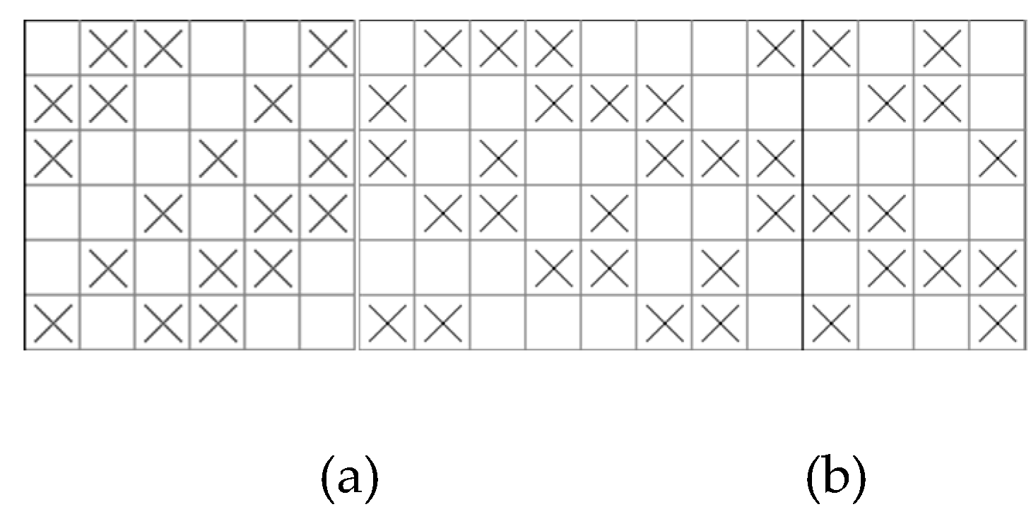
Figure 2.
Example of weave with different weave point distribution uniformity.
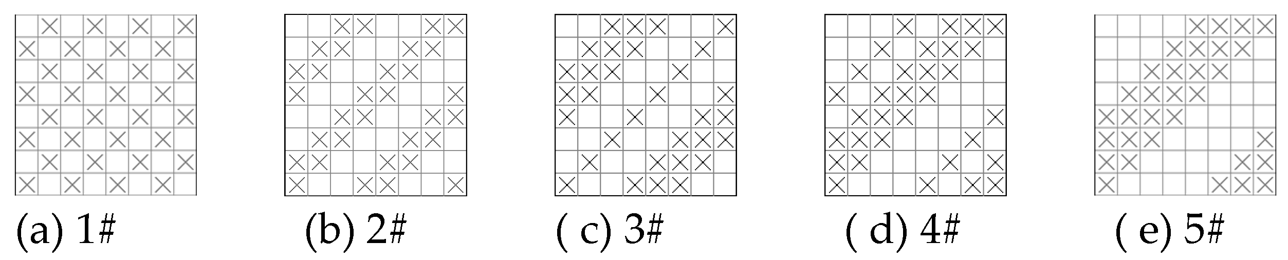
Figure 3.
Basic framework of the YWCAD module.
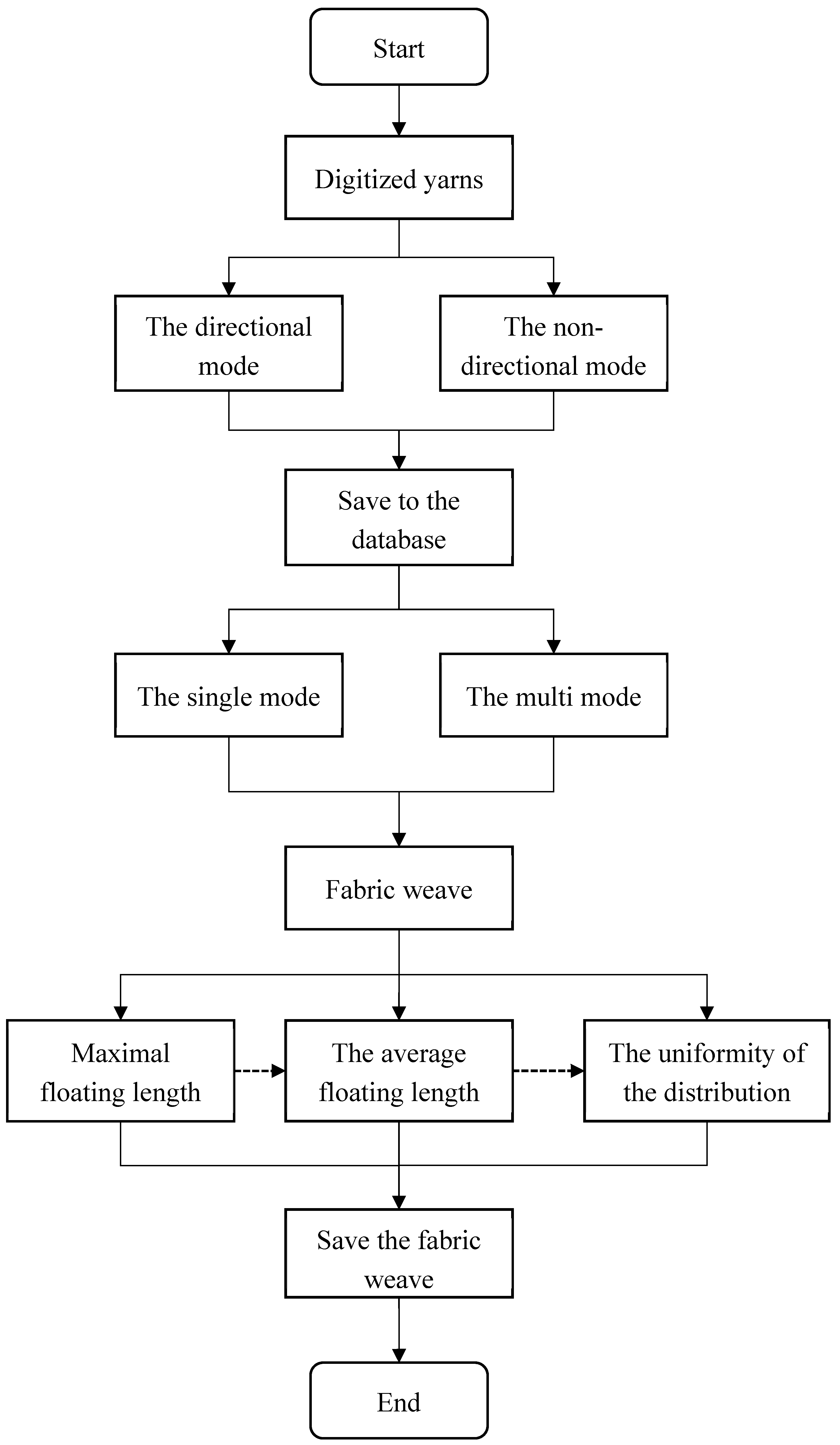
Figure 4.
Example weave for uniformity detection of weave point distribution.
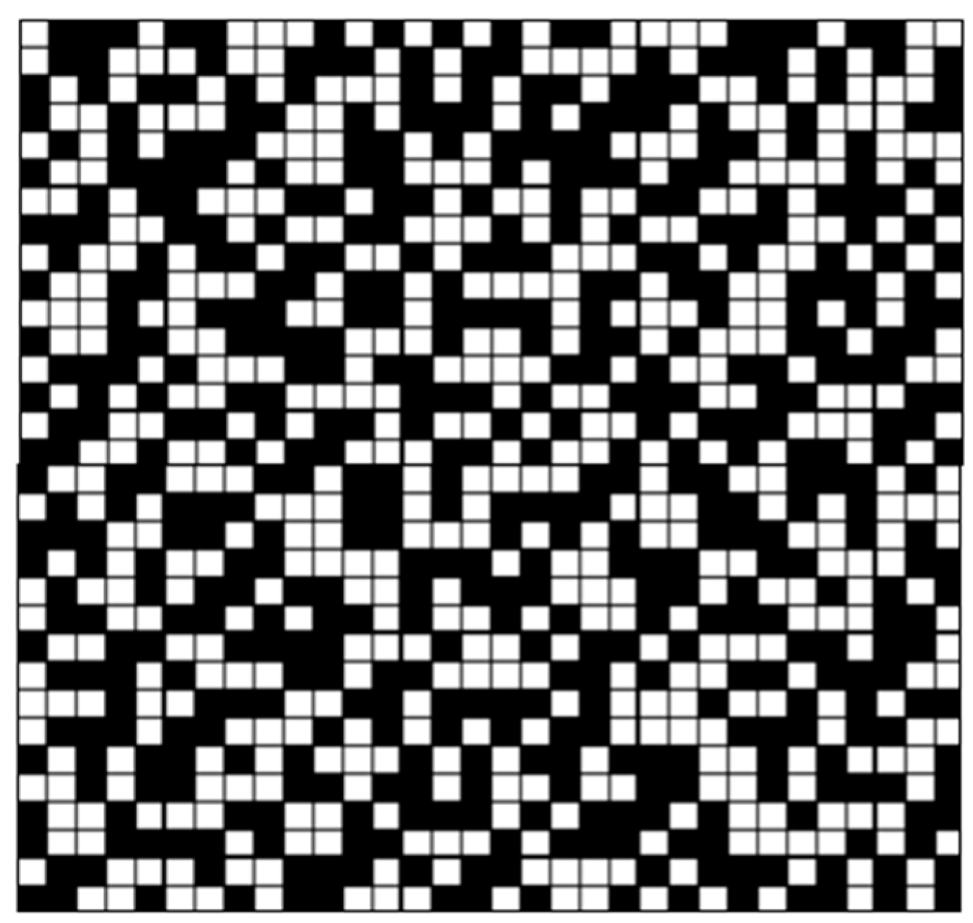
Figure 5.
Directional yarn generation.
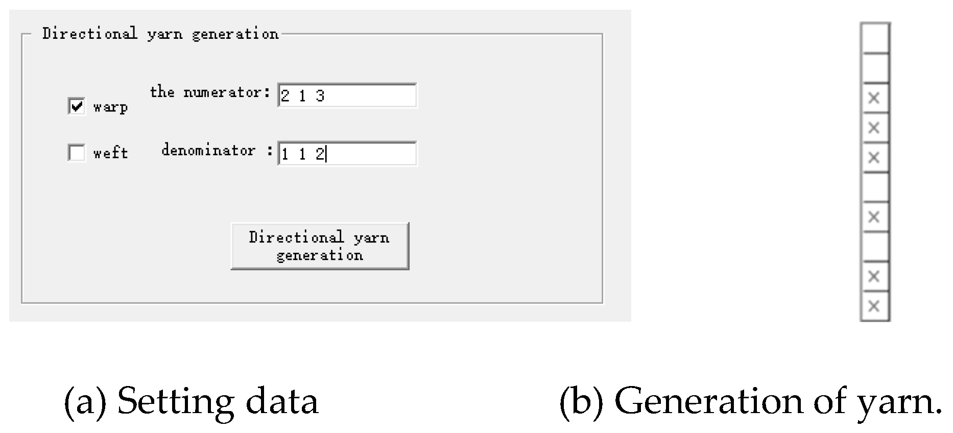
Figure 6.
Non-directional yarn generation.
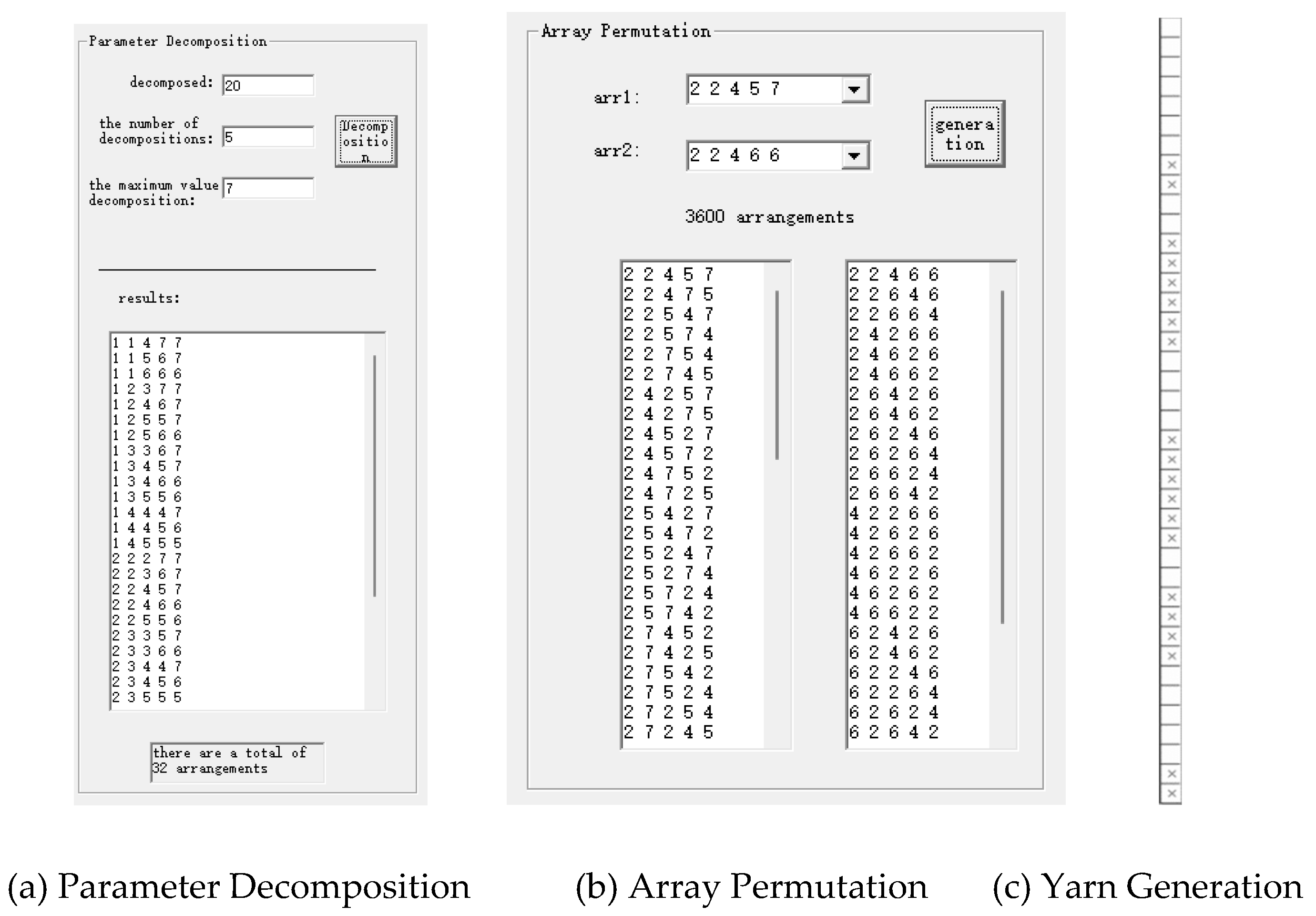
Figure 7.
Weave of fixed and regularized flyer generation.
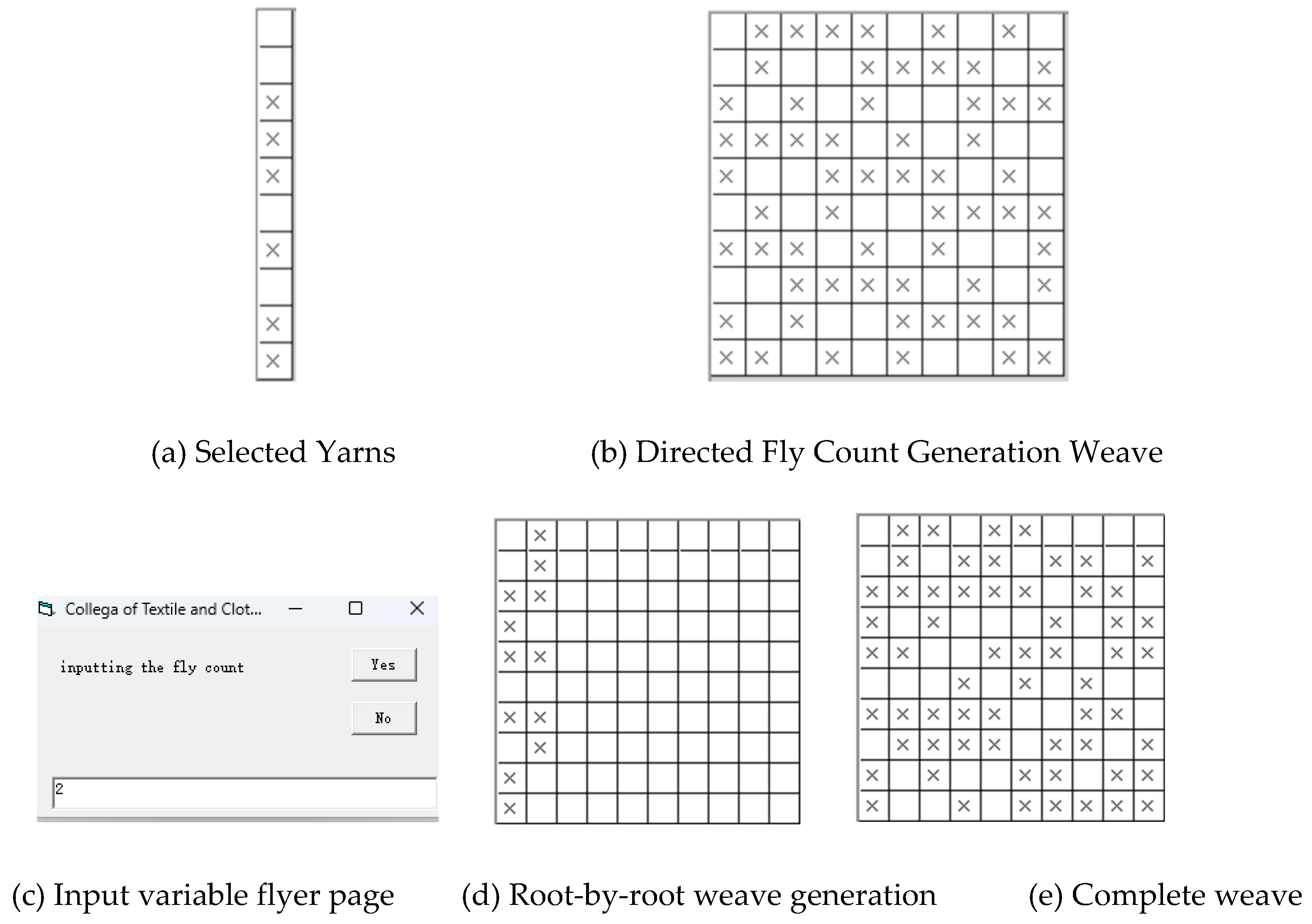
Figure 8.
Weave of random fly count generation.
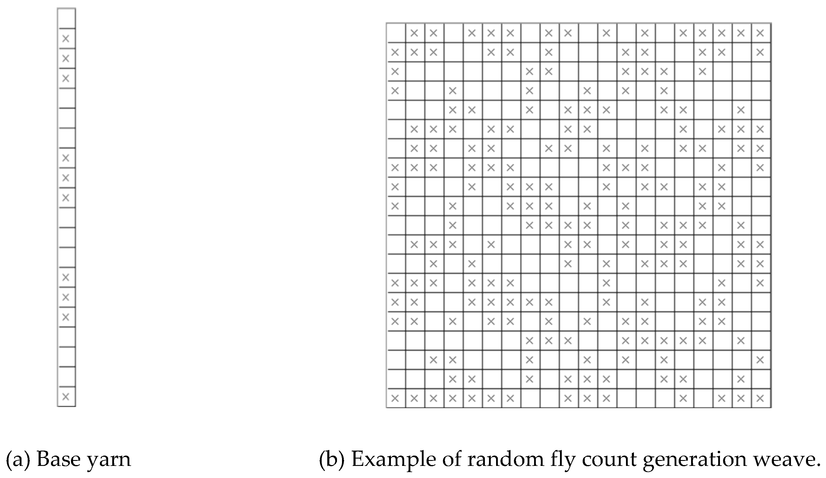
Figure 9.
Full random permutation generating weave.
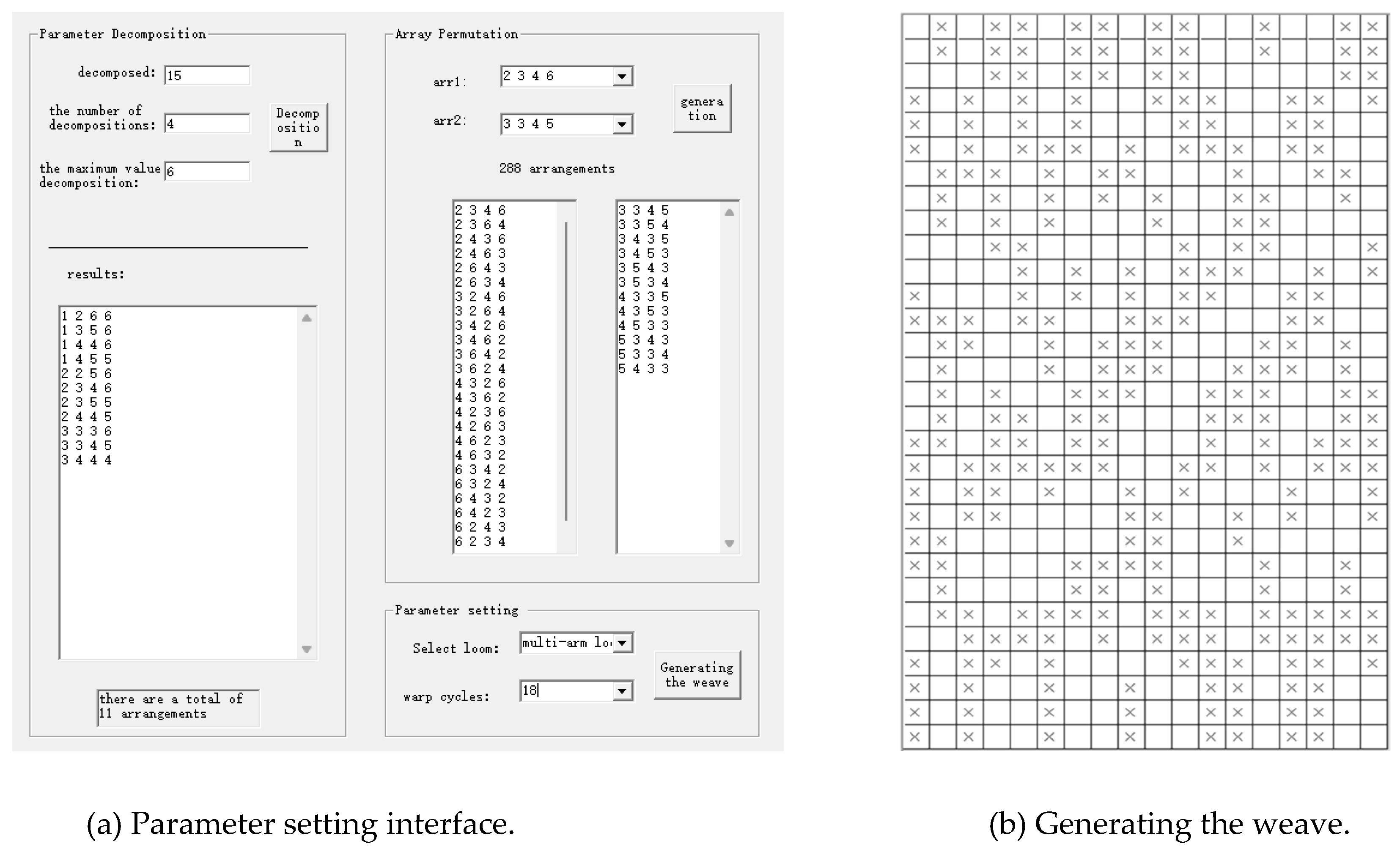
Figure 10.
Example of a database call to a yarn.
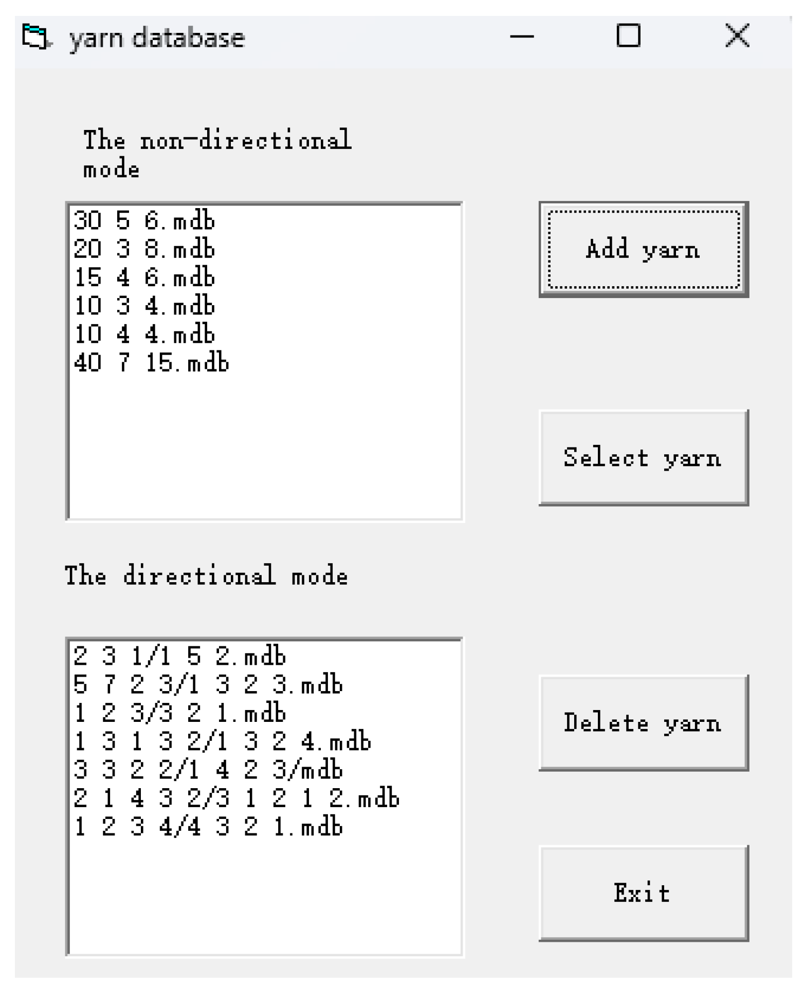
Figure 11.
Example of Directed Selection Directed Arrangement Directed Generation.
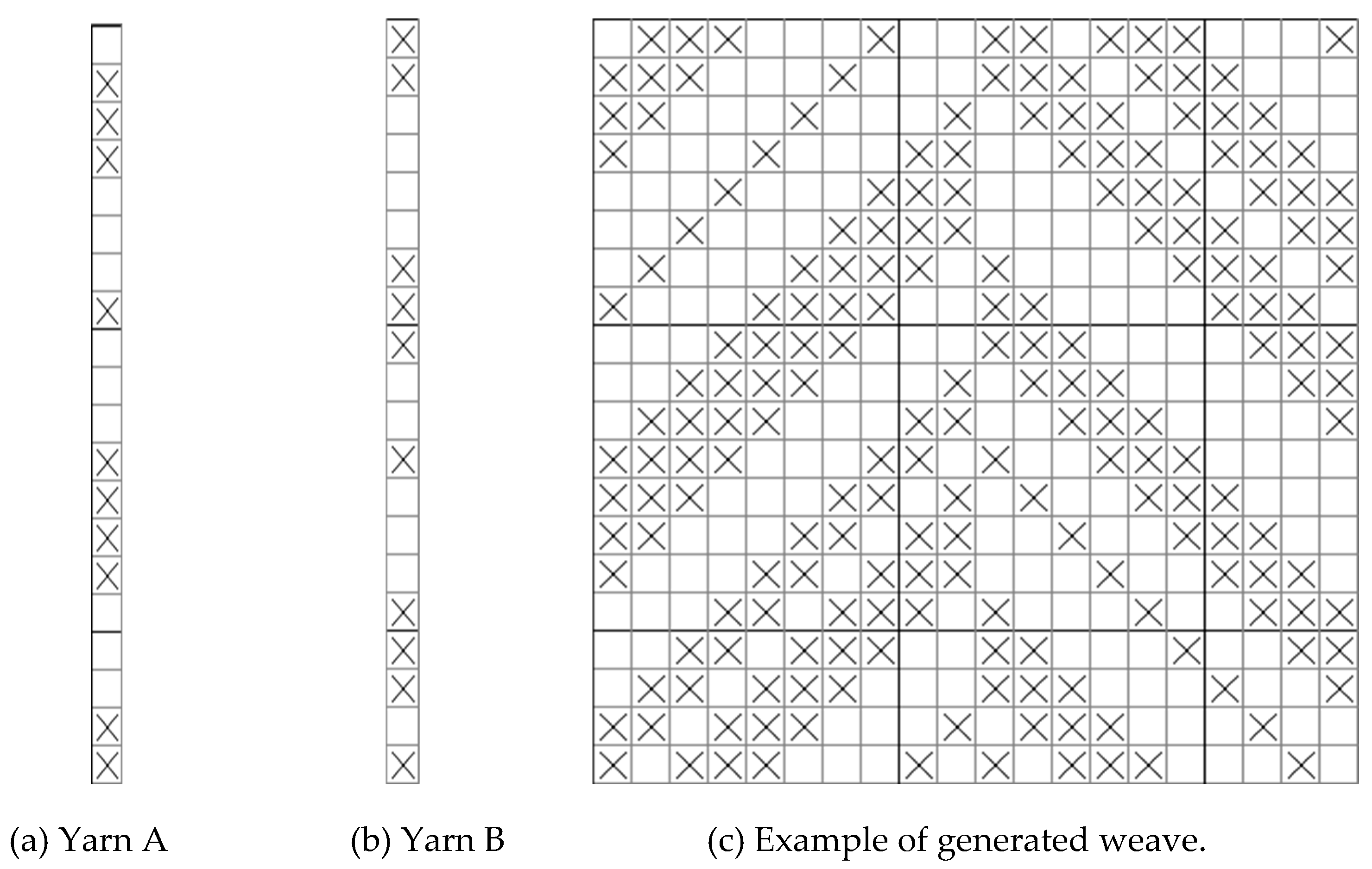
Figure 12.
Undirected Selection Directed Arrangement Directed Generation Example.
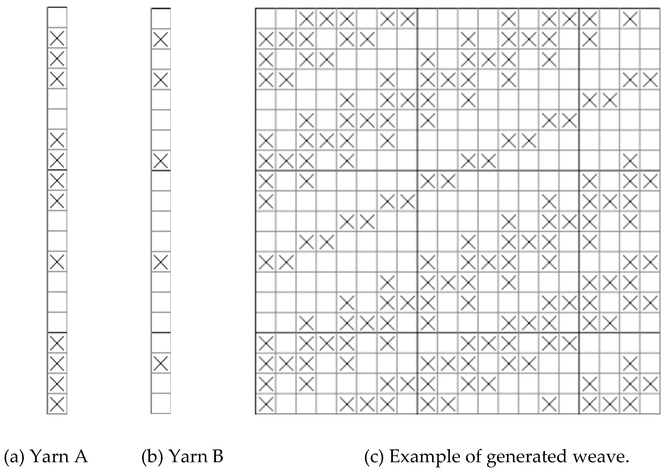
Figure 13.
Example of non-directed selection non-directed alignment non-directed generation.
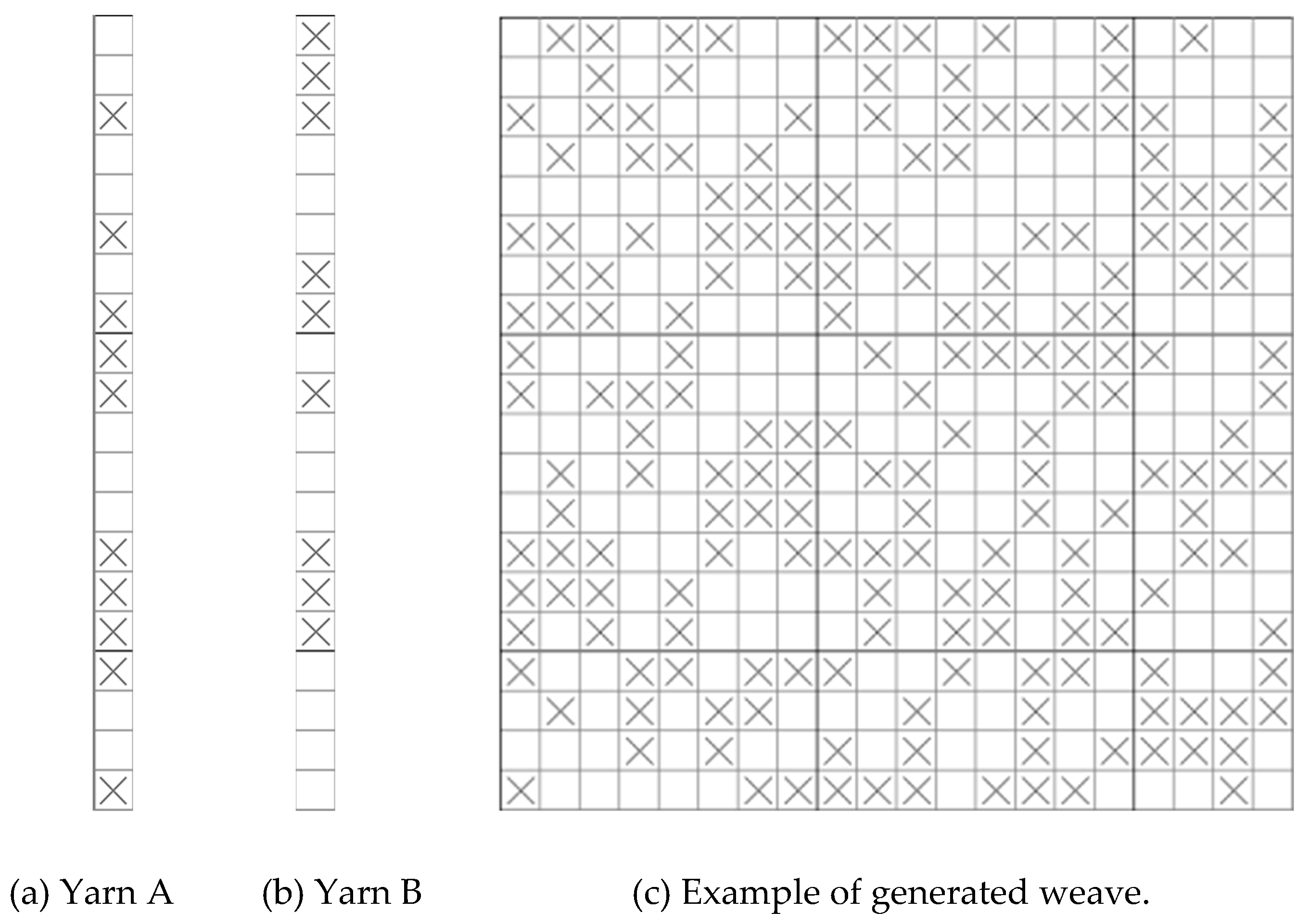
Figure 14.
Example of non-directed selection of directed arrangement of non-directed generation.
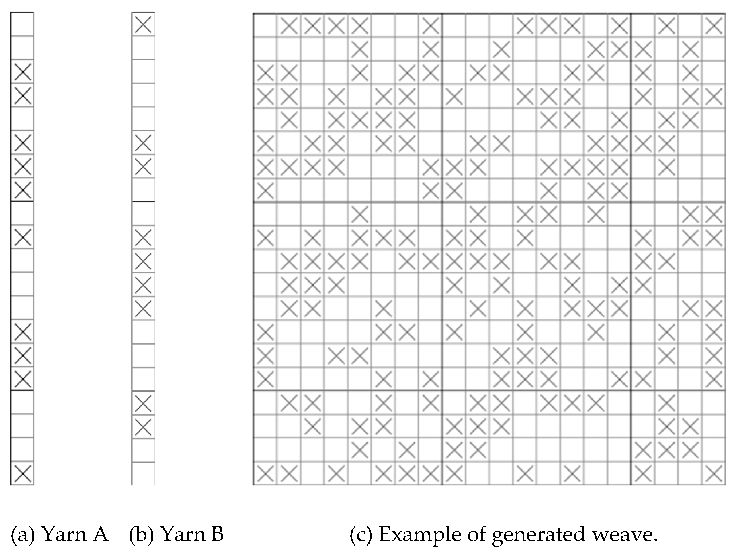
Figure 15.
Example of filtering function.
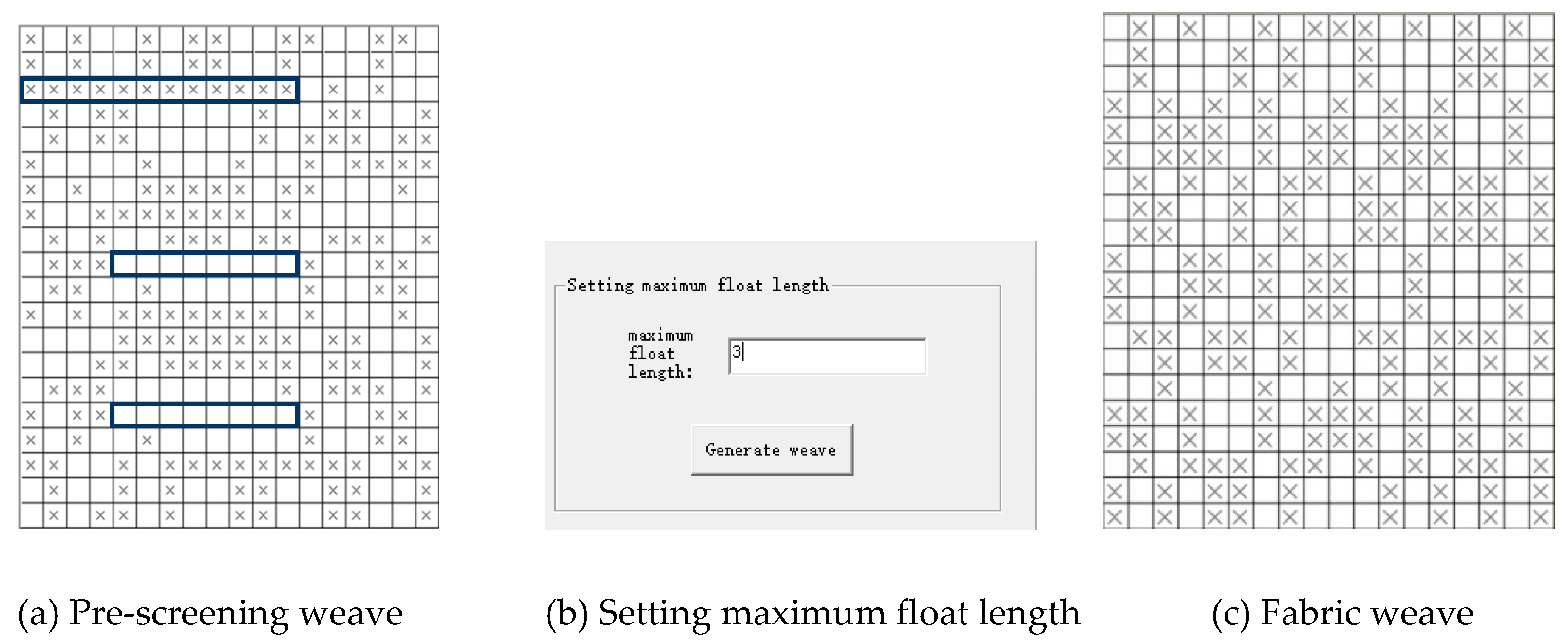
Figure 16.
Mean Float Length and Maximum Float Length Screening.
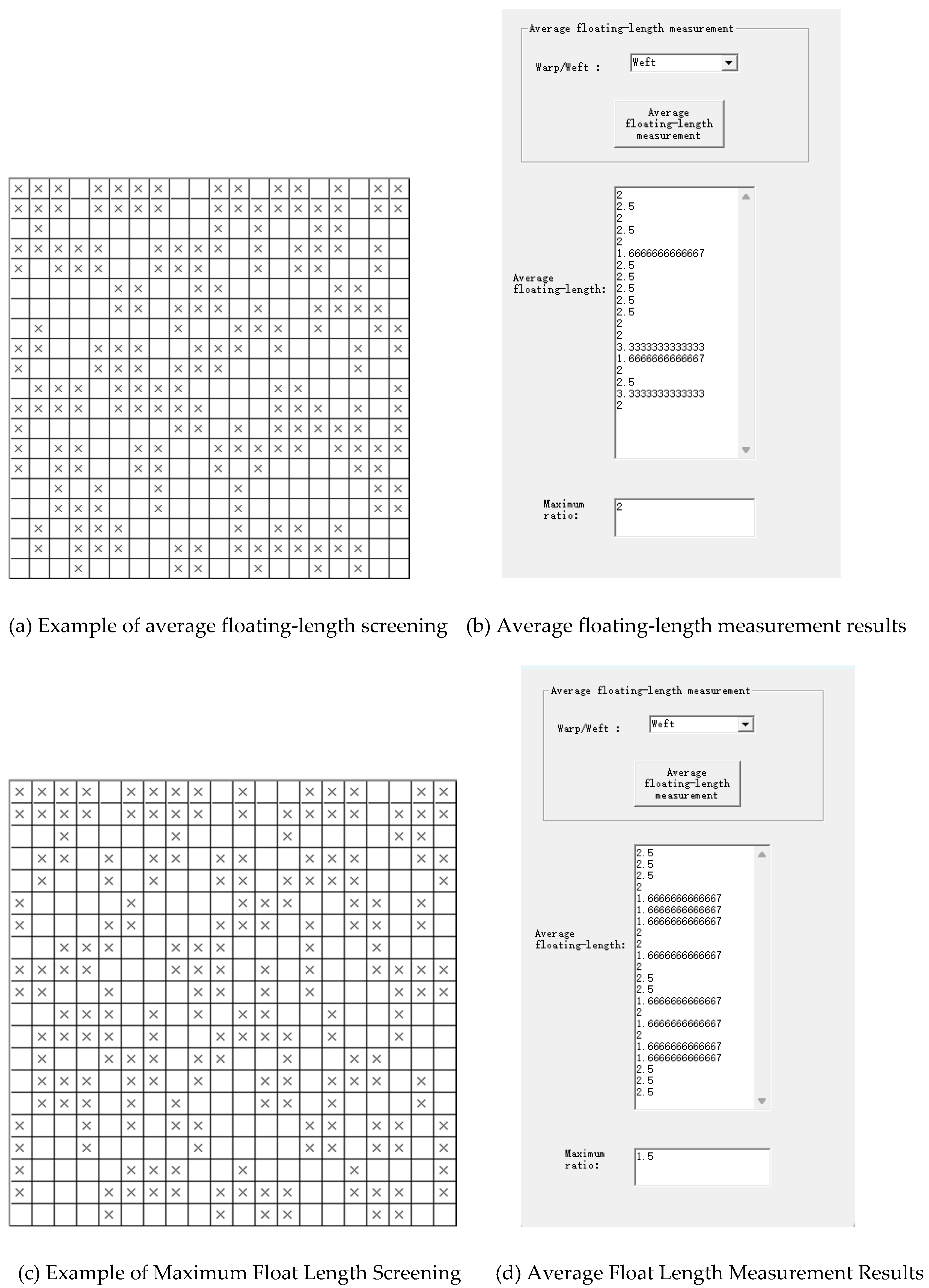
Figure 17.
Example of screening weave.

Table 1.
Comparison of the uniformity of weave point distribution for the weaves shown in Figure 2.
Table 1.
Comparison of the uniformity of weave point distribution for the weaves shown in Figure 2.
| Weave number | 2× 2 test area | 4× 4 Test Area | ||
| Characteristics of the situation | Number of different situations | Characteristics of the situation | Number of different situations | |
| 1# | Qj= Q(w) 2= | 1 | Qj= Q(w) 8= | 1 |
| 2# | Qj= 3 (Qw = 1), Qj= 1 (Qw = 3) | 2 | Qj= Q(w) 8= | 1 |
| 3# | Qj= Q(w)= 2, Qj= 3 (Qw = 1), Qj= 1 (Qw = 3), Qj= 4 (Qw = 0) |
4 | Qj= Q(w)= 8, Qj= 6 (Qw = 10), Qj= 10 (Qw = 6), Qj = 6 (Qw = 10) |
4 |
| 4# | Qj= Q(w)= 2, Qj= 4 (Qw = 0), Qj= 3 (Qw = 1), Qj= 1 (Qw = 3), Qj = 0 (Qw = 4) |
5 | Qj = 11 (Qw = 5), Qj = 9 (Qw = 7), Qj = 7 (Qw = 9), Qj = 5 (Qw = 11) |
4 |
| 5# | Qj= 4 (Qw = 0), Qj= 3 (Qw = 1), Qj= 1 (Qw = 3), Qj = 0 (Qw = 4) | 4 | Qj = 12 (Qw = 4), Qj= 10 (Qw = 6), Qj= 6 (Qw = 10), Qj = 4 (Qw = 12) | 4 |
Disclaimer/Publisher’s Note: The statements, opinions and data contained in all publications are solely those of the individual author(s) and contributor(s) and not of MDPI and/or the editor(s). MDPI and/or the editor(s) disclaim responsibility for any injury to people or property resulting from any ideas, methods, instructions or products referred to in the content. |
© 2025 by the authors. Licensee MDPI, Basel, Switzerland. This article is an open access article distributed under the terms and conditions of the Creative Commons Attribution (CC BY) license (http://creativecommons.org/licenses/by/4.0/).
Copyright: This open access article is published under a Creative Commons CC BY 4.0 license, which permit the free download, distribution, and reuse, provided that the author and preprint are cited in any reuse.


