
Submitted:
09 April 2025
Posted:
10 April 2025
You are already at the latest version
Abstract
Closed-Kinematic Chain Manipulators (CKCM) have gained attention due to their precise Cartesian motion capability through coordinated active joint movements. Furthermore, ensuring synchronization among the joints of CKCMs is critical for reliable operations. An advanced control scheme for CKCMs that combines Nonsingular Fast Terminal Sliding Mode Control (NFTSMC) with Time-Delay Estimation (TDE) while utilizing synchroniza-tion errors, namely Syn-TDE-NFTSMC, to effectively address joint errors in CKCMs was developed in [1, 2]. NFTSMC enables fast convergence through nonlinear terminal sliding while TDE eliminates the need for prior knowledge of the robot’s dynamics, thereby sim-plifying its implementation and reducing its computational requirements. The developed control scheme was rigorously evaluated in [1, 2] using computer simulation and its con-trol performance was compared with those of existing control methods. This paper pre-sents results of an experimental study where the developed control scheme was applied on a real CKCM with 2 degrees of freedom (DOF). Supported by computer simulation study conducted on this manipulator, experimental results show that this control scheme outperformed other existing control schemes in terms of synchronization and control per-formance. The results confirm the efficacy of the developed control scheme in enhancing control precision and system stability, making it a promising solution for improving CKCM control strategies in real-world applications.
Keywords:
file:///C:/Users/Admin/Downloads/preprints-155313-manuscript_layout_doneClosed-Kinematic Chain Manipulator (CKCM)
; sliding mode control (SMC)
; time-Delay Estimation (TDE)
; Nonsingular Fast Terminal Sliding Mode Control (NFTSMC)
; synchronization control
; and model-free control
; Stewart Platform
; degrees-of-freedom (DOF)
; linear voltage differential transformer
; Linear Position Sensors
; data acquisition board
1. Introduction
Closed-Kinematic Chain Manipulators (CKCMs) have drawn significant attention in the robotics community due to their ability to achieve precise Cartesian motion through coordinated active joint movements. Compared to Open-Kinematic Chain Manipulators (OKCM), CKCMs offer improved positioning accuracy and payload handling capabilities [3,4,5,6]. However, CKCMs also present challenges, including limited workspace, absence of closed-form solutions for forward kinematics, and synchronization issues among joints and end-effectors. Since synchronization errors can degrade tracking accuracy and even damage the mechanical structure, especially under high accelerations or abrupt payload changes, various synchronization-based control schemes have been developed [7,8,9,10,11].
To implement effective control schemes on a real robot in real-time, the control laws must have simple structures and should not rely on knowledge of the manipulator’s dynamics. As a result, synchronized adaptive and PD control schemes are explored in [12,13,14] for this purpose. Additionally, a traditional sliding mode control (SMC) scheme developed by authors in [1,15] was employed to control the motion of CKCMs. SMC is advantageous due to its robustness against uncertainties and disturbances to the system parameter variations, making it suitable for CKCMs [1,2,16,17]. However, the SMC approach applied to manipulators can only guarantee asymptotic stability, requiring finite time to converge to an equilibrium.
To achieve finite-time convergence, the terminal SMC (TSMC) scheme was developed in [18,19,20]. This approach includes a driving component that forces the system's trajectory to a stable sliding surface, which is designed to enforce the system’s desired error dynamics. However, TSMC has two main limitations: slower convergence to equilibrium as compared to the traditional SMC when the system state is far from the equilibrium, and an issue dealing with singularity [21,22]. To address these, an enhanced version called Nonsingular Fast Terminal Sliding Mode Control (NFTSMC) was introduced in [23,24], incorporating synchronization for controlling a parallel robot manipulator. This improved control scheme overcomes singularity and achieves fast convergence, [25]. Despite its advantages, the gain selection in NFTSMC still depends on conservative estimates of the manipulator’s dynamic model, resulting in calculational challenges due to the highly complicated dynamic model of the manipulator. To overcome this issue, a model-free controller utilizing time-Delay Estimation (TDE) was developed. Over the past decade, TDE-based controllers have been widely applied for robot manipulators due to their computation efficiency [26,27,28]. By using time-delayed information, TDE effectively estimates unknown dynamics and disturbances within a sufficiently small time-delay. Additional, the TDE has been combined with Nonsingular Terminal Sliding Mode (NTSM) control [29] to deliver highly robust and precise control with fast, finite-time convergence.
A recent study in [2] introduced a TDE-based NFTSMC scheme with synchronization error handling, namely Syn-TDE-NFTSMC for CKCMs. Simulation study indicated that this control scheme outperformed existing control schemes including LINEAR, TDE-based LINEAR, TDE-based LINEAR with synchronization errors, and TDE-based SMC with synchronization errors in controlling the CKCM motion. However, experimental validation of this approach has not been conducted. This paper focuses on the experimental aspect of the above control scheme and is organized as follows. Section 2 describes the main components of a real CKCM possessing 2 degrees of freedom (DOF) to be employed in our experimental study. Section 3 contains the implementation of the developed Syn-TDE-NFTSMC to control the motion of the above manipulator. Results of experimental study are presented and discussed in Section 4. Section 5 concludes the paper with comments, key findings and future research directions.
2. The Real 2-DOF CKCM
This section describes the main components of a real 2-DOF CKCM of the Robotics and Intelligent Control Laboratory (RICL) of the School of Engineering at Catholic University of America (CUA). This manipulator was built as a prototype to demonstrate the capability of high precision motion of CKCMs for potential applications in space assembly. Figure 1 shows the manipulator consisting of two links, each composed of a ball-screw linear actuator driven by a direct current (DC) motor. The top end of the links is suspended below a fixed platform, and the links are connected to the platform by two pin joints acting as revolute joints. The other ends of the links are coupled together by the same type of revolute joints to which an end-effector is mounted. Two linear voltage differential transformers (LVDT) mounted along the links serve as position sensors to provide real-time information of the link lengths. Table 1 presents the manipulator parameters and the specifications of the ball screw actuators.
The LVDT position sensors are precision linear variable differential transformers, encapsulated in a metal housing. An external Alternating Current (AC) source excites the primary, producing magnetic flux within the transducer. Consequently, this induces voltages in the two secondaries, whose magnitude varies with the position of the core. The secondaries are connected in series opposition, producing a total output voltage that is essentially zero when the core is at the electrical center of the unit, and which increases linearly when the core is displaced in either direction from the electrical center. The transducers can be excited at frequencies varying from 400 Hz to 10 kHz. Table 2 provides the main characteristics of the LVDTs.
Figure 2 illustrates the block diagram of the manipulator control system. The interfacing between the outside world, consisting of the robot manipulator, sensors, amplifiers, and computer processing unit, is done through a data acquisition system (DAQ). The DAQ in this system is a NI BNC 2120 DAQ board that can support two analog inputs and two analog outputs by BNC connections. The voltage of the input and output channels can be selected to be either unipolar (0 to 10 volts) or bipolar (± 5 volts or ± 10 volts). The sampling rate is set to 1 kHz by the compatible software package LabView in the processing unit. LabView is a graphical software that allows for data acquisition and real-time analysis to be performed.
The frame assignment of the manipulator is shown in Figure 3 where the lengths of its links, and are denoted as its joint variables.
From Figure 3, we obtain
where d is the distance between the pin joints hanging the two actuators and (x, y) represents the Cartesian position of the manipulator.
Equations (1) and (2) provides a closed-form solution for the inverse kinematics, meaning they can be used to calculate the link lengths and from the desired Cartesian position (x, y).
Additionally, from (1)-(2), the Cartesian variables x and y can be derived as follows.
These (3) and (4) offer a closed-form solution for the forward kinematics, allowing the determination of a Cartesian position (x, y) based on the link lengths and .
We proceed to derive the dynamic model the manipulator. Its Lagrangian dynamic equations can be obtained as a special case of the general equations (5) with n=2 as
with
where denotes the joint force of the ith actuator, respectively, for i = 1,2.
The inertia matrix, the Centrifugal and Coriolis forces, and the friction and the gravitational forces at two joints are given by the following [30]:
with
and the following is obtained.
3. The Control Scheme
The Syn-TDE-NFTSMC scheme developed in [2] is now applied to control the motion of the manipulator described in Section 2 above. As shown in Figure 4, the developed control system for the manipulator mainly consists of three subsystems: the Synchronization Subsystem, the NFTSMC Subsystem, and the TDE Subsystem.
The operation of the control system is briefly explained as follows. As the input of the control scheme, the Cartesian vector representing the desired manipulator’s Cartesian configuration (position and orientation), is either specified by the user or generated by a trajectory planner. This vector is then converted into its corresponding joint vector through the Inverse Kinematic Transformation specified by Equations (1) and (2). The actual joint variables and acquired by the LVDTs constitute the actual joint vector . Then, both the desired joint vector and the actual joint vector are sent to the Synchronization Subsystem. This subsystem calculates the position error for each active joint for Joint 1 and Joint 2, the synchronization error , and the cross-coupling error between the two joints. The cross-coupling error is then processed by the NFTSMC, which defines a sliding surface to regulate error behavior. Next, the control law is formulated based on this sliding surface, ensuring that the system trajectory converges to a stable hyperplane (sliding surface). This control law then serves as a key component of the input to the actuators of the manipulator to ensure asymptotic convergence of both position and synchronization errors in minimal time. Additionally, the TDE Subsystem utilizes past control inputs and the acceleration data with the , a constant, selected diagonal matrix in the estimate time delay L to estimate all nonlinear terms system dynamics , which includes the inertia uncertainty, Coriolis/centripetal vector, gravitational vector, friction vector, and disturbances, and disturbance torques . These estimates are essential for generating the control input applied to the manipulator, ensuring robust and precise control performance under varying dynamic conditions.
We proceed to implement the Syn-TDE-NFTSMC developed in [2] to control the motion of the manipulator. First the dynamics of the manipulator specified by (5) can be simplified as
where including the manipulator dynamics with disturbance torques can be denoted as
According to [2], the control input in (11) is derived by
with
is an estimation of , in a minimum sampling time L and can be presented as
The control law u is expressed as follows
with
where
- , , , , , denote the joint force, pass joint force, control law, sliding surface, past acceleration vectors of the ith actuator, and ith desired acceleration joint, respectively, for i = 1, 2.
- , , , and are positive odd integers, , .
- The nonsingular terminal sliding surface is defined as
- , a past acceleration vector can be computed as
- , , and are diagonal design matrices, are given by the following:
; ; ;
The cross-coupling error can be expressed as follows:
where and are tracking errors and synchronization errors, respectively. and α are 2 × 2 identity matrix and 2 × 2 diagonal positive definite matrix, respectively and D is the synchronization transformation matrix. Thus we have
As shown in (13), the input to the manipulator consists of two primary components, a TDE-based input and an NFTSM input. The TDE-based component minimizes the influence of the unknown dynamics in the manipulator dynamics, ensuring that the system can handle uncertainties in the model more effectively. On the other hand, the NFTSM component is designed to asymptotically drive both the cross-coupling errors and tracking error to converge to zero, thereby enhancing the accuracy of the control system overtime.
Moreover, the application of the TDE brings a further advantage to the control scheme. Instead of directly computing the complex and computationally intensive dynamic parameters , the TDE-based component can be derived with the estimate of using (14). This approach significantly improves the efficiency of the control system by minimizing the computational burden. By combining both the TDE-based and NFTSM components, the control system is able to handle both model uncertainties and convergence of errors, providing a robust solution for controlling the manipulator.
4. Experiment Study
This section presents an experimental study conducted to study the performance of the developed Syn-TDE-NFTSMC in comparison with that of other existing control schemes when they are employed to control the motion of the manipulator.
In our experimental study, the developed Syn-TDE-NFTSMC and other existing control schemes were used to control the manipulator to track a circular motion specified by and as follows.
In [2], computer simulation was performed to evaluate the performance of the developed Syn-TDE-NFTSMC and several existing control schemes including LINEAR, TDE-based LINEAR, TDE-based LINEAR with synchronization errors, and TDE-based SMC with synchronization errors with tracking the same motion. Simulation results indicated that the incorporation of TDE and the synchronization errors enhanced the performance of the control schemes. Of all of the control schemes, the Syn-TDE-NFTSMC delivered the desired trajectory with the smallest deviation and the fastest error convergence in comparison to other control schemes.
In this experimental study, we will compare the performance of the Syn-TDE-NFTSMC with that of two existing control schemes including TDE-based LINEAR with synchronization errors (Syn-TDE-PID) and TDE-based SMC with synchronization errors (Syn-TDE-SMC) when tracking the same motion for a 2-DOF-CKCM.
The optimal control parameters obtained in the computer simulation [2] for best tracking performance served as the basis for selecting the actual control parameters of the three control schemes in our experimental study. After conducting numerous experiments with all three control schemes, the most optimal control parameters were finalized and are tabulated in Table 3.
Results from the experimental study are shown in Figure 5, Figure 6, Figure 7, Figure 8 and Figure 9 and Table 4, Table 5 and Table 6. These results are used to compare with those of the computer simulation study conducted in [2]. In general, due to experimental conditions, such as sensor inaccuracies, environmental factors, and mechanical limitations, the experimental results showed slightly higher tracking errors as compared to computer simulation results.
Figure 5, Figure 6, Figure 7, Figure 8 and Figure 9 indicate that incorporating TDE and synchronization errors greatly enhanced the performance of the control schemes. Our developed control scheme, Syn–TDE-NFTSMC, closely followed the desired trajectory (as seen in Figure 5) with minimal deviation from the desired path and demonstrate rapid error convergence.
Despite these practical challenges, the trends observed in the experiments largely align with those seen in the simulations. The Syn-TDE-PID strategy exhibited AATEs of 0.7 mm and 0.8 mm for Joint 1 and Joint 2, respectively. However, the Syn-TDE-SMC and Syn-TDE-NFTSMC still showed notable improvements, with errors of 0.2 mm and 0.1 mm in both cases. The experimental results demonstrate that the Syn-TDE-NFTSMC controller is the most effective in reducing tracking errors in real-world applications, followed closely by Syn-TDE-SMC.
In the experimental setup, the trends observed in the simulation remain consistent, although the AASEs and AACEs are higher. Regarding synchronization errors, the Syn-TDE-PID controller shows the highest AASEs, with values of 0.24 mm and 0.32 mm for Joint1 and Joint 2, respectively. In contrast, Syn-TDE-SMC and Syn-TDE-NFTSMC show smaller AASEs, with Syn-TDE-SMC having values of 0.134 mm and 0.19 mm, while Syn-TDE-NFTSMC delivers the best performance, with AASEs of 0.06 mm and 0.15 mm. The same trend is observed for AACEs, as shown in Table 5, where Syn-TDE-NFTSMC outperforms the other controllers. These results indicate that Syn-TDE-NFTSMC provides the most effective performance overall, minimizing both synchronization and cross-coupling errors in both simulation and experimental scenarios.
Table 6 presents the AAEE of the Syn-TDE-PID, Syn-TDE-SMC, and Syn-TDE-NFTSMC controllers in the experimental setup. In the simulation, the AAEE values remain identical across all three controllers, measuring 0.0177 Nm for Joint 1 and 0.0172 Nm for Joint 2. However, the experimental results show some variation compared to the simulation. Syn-TDE-PID exhibits the highest estimation error at 0.03 Nm, whereas Syn-TDE-SMC and Syn-TDE-NFTSMC achieve significantly lower errors of 0.01 Nm and 0.017 Nm, respectively, for Joint 1. A similar trend is observed for Joint 2 across all three control schemes. This indicates that, in the experimental study, Syn-TDE-SMC and Syn-TDE-NFTSMC provide more accurate estimation compared to Syn-TDE-PID.
In summary, the results demonstrate that the developed control scheme Syn-TDE-NFTSMC surpasses the performance of existing control schemes, as confirmed by comprehensive simulations and experimental validation on a 2-DOF CKCM. The developed control scheme was proven to be highly accurate, easily implementable, and robust against parameter variations. Furthermore, the incorporation of synchronization errors significantly enhanced the overall performance of the control scheme, ensuring precise and reliable operation.
5. Conclusion
This paper focuses on experimental performance evaluation of an advanced sliding mode control scheme, namely the Synchronization Time-Delay Estimation Nonlinear Fast Terminal Sliding Mode Control (Syn-TDE-NFTSMC) that was developed in [2]. Overall, by leveraging synchronization errors and integrating the Time-Delay Estimation (TDE) method with a Nonsingular Fast Terminal Sliding Mode Controller (NFTSMC), the developed control scheme effectively minimized synchronization errors while maintaining computational efficiency. The TDE approach eliminated the need for explicit computation of complex manipulator dynamics, making the control scheme particularly suitable for real-time applications. Furthermore, the stability of the control system was rigorously proven using the Lyapunov Theorem, ensuring uniform stability throughout its operation. Results of experiments conducted to evaluate the control performance of the developed control scheme when applied to control the motion of a real 2-DOF CKCM showed that the developed control scheme outperformed existing control schemes. Obtained results underscore the practicality and reliability of the Syn-TDE-NFTSMC scheme for achieving precise synchronization and robust control in CKCMs. The ability to adapt to different manipulator configurations while reducing computational complexity further enhances its appeal for real-world robotic applications.
Future research directions include extending the developed control scheme to manipulators with higher degrees of freedom (DOF). This could involve combining the Syn-TDE-NFTSMC approach with other advanced control strategies including adaptive control and intelligent control. These efforts would further explore the scalability and performance of the developed scheme, paving the way for its application in more complex robotic systems.
Author Contributions
Conceptualization, T.T.C.D., C.C.N., and T.D.T.; methodology, T.T.C.D. and C.C.N.; software, T.T.C.D. and C.C.N.; validation, T.T.C.D. and C.C.N.; results analysis, T.T.C.D. and T.D.T.; investigation, C.C.N., T.T.C.D., and T.D.T.; data curation, T.T.C.D. and T.D.T.; writing—original draft preparation, C.C.N., T.T.C.D., and T.D.T.; writing—review and editing, C.C.N. and T.T.C.D.; visualization, C.C.N. and T.T.C.D.; supervision, C.C.N. and T.T.C.D. All authors have read and agreed to the published version of the manuscript.
Funding
This research received no external funding.
Institutional Review Board Statement
Not applicable
Informed Consent Statement
Not applicable
Data Availability Statement
Not applicable
Conflicts of Interest
All authors announce that they have no conflicts of interest in relation to the publication of this article.
Appendix-Existing Control Schemes Used in Experiment Study
This appendix contains relevant equations of control schemes to which the developed control scheme is compared to in our experiment study.
TDE-based PID with synchronization errors (Syn-TDE-PID)
TDE-based SMC with synchronization errors (Syn-TDE-SMC) [1]
References
- Duong, T., Tran, T., Nguyen, T., Duong, N., Synchronization Sliding Mode Control with Time-Delay Estimation for a 2-DOF Closed-Kinematic Chain Robot Manipulator. 2021 International Conference on System Science and Engineering (ICSSE), 2021.
- Duong, T.T.C., C.C. Nguyen, and T.D. Tran, Synchronization Sliding Mode Control of Closed-Kinematic Chain Robot Manipulators with Time-Delay Estimation. Applied Sciences, 2022. 12(11): p. 5527. [CrossRef]
- Patel, Y.D. and P.M. George, Parallel Manipulators Applications—A Survey. Modern Mechanical Engineering, 2012. 02(03): p. 57-64.
- Nguyen, C. and F..Pooran, Kinematic analysis and workspace determination of a 6 dof CKCM robot end-effector. Journal of Mechanical Working Technology, 1989. 20: p. 283. [CrossRef]
- Nguyen, C.C. and F.J. Pooran, Dynamic analysis of a 6 DOF CKCM robot end-effector for dual-arm telerobot systems. Robotics and autonomous systems, 1989. 5(4): p. 377. [CrossRef]
- Nguyen, C.C., Antrazi, S. S, Zhou, Z.-L. and Campbell, Jr. C. E. C., Adaptive control of a stewart platform-based manipulator. Journal of robotic systems., 1993. 10(5): p. 657.
- Nijmeijer, A.R.-A.H., Mutual Synchronization of Robots via Estimated State Feedback: A Cooperative Approach. IEEE transactions on control systems technology : a publication of the IEEE Control Systems Society., 2004. 12(4): p. 542-554.
- J.K.Mills, A.S., Adaptive synchronized control for coordination of multirobot assembly tasks. IEEE transactions on robotics and automation : a publication of the IEEE Robotics and Automation Society., 2002. 18(4): p. 498-509.
- Vinh, D.Q., L.T. Dung, and Vo Anh Tuan, Synchronization Full-Order Terminal Sliding Mode Control for an Uncertain 3-DOF Planar Parallel Robotic Manipulator. Applied Sciences, 2019. 9(9): p. 1756.
- Koren, Y., Cross-coupled biaxial computer control for manufacturing systems. 1980. [CrossRef]
- Su, Y., Sun, D., Ren, L. and Mill, J.K, Integration of saturated PI synchronous control and PD feedback for control of parallel manipulators. IEEE transactions on robotics : a publication of the IEEE Robotics and Automation Society., 2006. 22(1): p. 202. [CrossRef]
- Zhao, D., Li, S., Gao, F. and Zhu, Q. Fully adaptive feedforward feedback synchronized tracking control for Stewart Platform systems. International Journal of Control, Automation, and Systems, 2008. 6(5): p. 689-70.
- Su, Y.X., Sun, D., Ren, L, Wang, X. and Mills, J. K., Nonlinear PD Synchronized Control for Parallel Manipulators. Proceedings of the 2005 IEEE International Conference on Robotics and Automation.
- Duong, T., C.C. Nguyen, and T.D. Tran, An Advanced PD Controller for Robot Manipulators with Time-Delay Estimation, in 2022 World Automation Congress (WAC). 2022.
- Tran, D.T., H.V. Dao, and K.K. Ahn, Adaptive synchronization sliding mode control for an uncertain dual-arm robot with unknown control direction. Applied Sciences, 2023. 13(13): p. 7423. [CrossRef]
- Dinh, T.X., Thien, T. D., Anh, T. H. V., and Ahn, K. K., Disturbance Observer Based Finite Time Trajectory Tracking Control for a 3 DOF Hydraulic Manipulator Including Actuator Dynamics. IEEE Access, 2018. 6: p. 36798-36809. [CrossRef]
- Nuno, E., L. Basanez, and R. Ortega. Adaptive control for the synchronization of multiple robot manipulators with coupling time-delays. in 2010 IEEE/RSJ International Conference on Intelligent Robots and Systems. 2010. IEEE.
- Zhao, D., S. Li, and F. Gao., A new terminal sliding mode control for robotic manipulators. International journal of control., 2009. 82(10): p. 1804. [CrossRef]
- Zhihong, M., A. Paplinski, and H. Wu, A robust MIMO terminal sliding mode control scheme for rigid robotic manipulators. IEEE transactions on automatic control., 1994. 39(12): p. 2464. [CrossRef]
- Tang., Y., Terminal sliding mode control for rigid robots. Automatica, 1998. 34(1): p. 51. [CrossRef]
- Xia, Y., Zhang, J., Lu, K. and Zhou, N., Finite Time and Cooperative Control of Flight Vehicles. 1 ed. Advances in Industrial Control. 2019: Springer Singapore. XXVI, 400.
- Shtessel, Y., Edwards, C., Fridman, L. and Levant, A., Sliding Mode Control and Observation. 2014: Birkhäuser Basel.
- Yang, L. and J. Yang, Nonsingular fast terminal sliding-mode control for nonlinear dynamical systems. International Journal of Robust and Nonlinear Control, 2011. 21(16): p. 1865. [CrossRef]
- Van, M., S.S. Ge, and H. Ren., Finite Time Fault Tolerant Control for Robot Manipulators Using Time Delay Estimation and Continuous Nonsingular Fast Terminal Sliding Mode Control. IEEE transactions on cybernetics., 2017. 47(7): p. 1681. [CrossRef]
- Zhao, D., S. Li, and F. Gao., Finite time position synchronised control for parallel manipulators using fast terminal sliding mode. International Journal of Systems Science, 2009. 40(8): p. 829. [CrossRef]
- Hsia, T., T. Lasky, and Z. Guo., Robust independent joint controller design for industrial robot manipulators. IEEE transactions on industrial electronics a publication of the IEEE Industrial Electronics Society., 1991. 38(1): p. 21.
- Baek, J., S. Cho, and S. Han, Practical Time-Delay Control With Adaptive Gains for Trajectory Tracking of Robot Manipulators. IEEE transactions on industrial electronics a publication of the IEEE Industrial Electronics Society., 2018. 65(7): p. 5682.
- Bae, H.-J., Jin, M., Suh, J., Lee, J. Y, Chang, P.-H and Ahn, D.-S, Control of Robot Manipulators Using Time-Delay Estimation and Fuzzy Logic Systems. Journal of Electrical Engineering and Technology, 2017. 12(3): p. 1271. [CrossRef]
- Maolin, J., Jinoh, L., Pyung, H. C., and Chintae, C., Practical Nonsingular Terminal Sliding-Mode Control of Robot Manipulators for High-Accuracy Tracking Control. IEEE transactions on industrial electronics a publication of the IEEE Industrial Electronics Society., 2009. 56(9): p. 3593.
- Jabbari, P.F., Dynamics and control of robot manipulators with closed-kinematic chain mechanism. 1990, Thesis (Ph. D.--Mech. Eng.)--Catholic University of America, 1990.
Figure 1.
The 2-DOF CKCM.
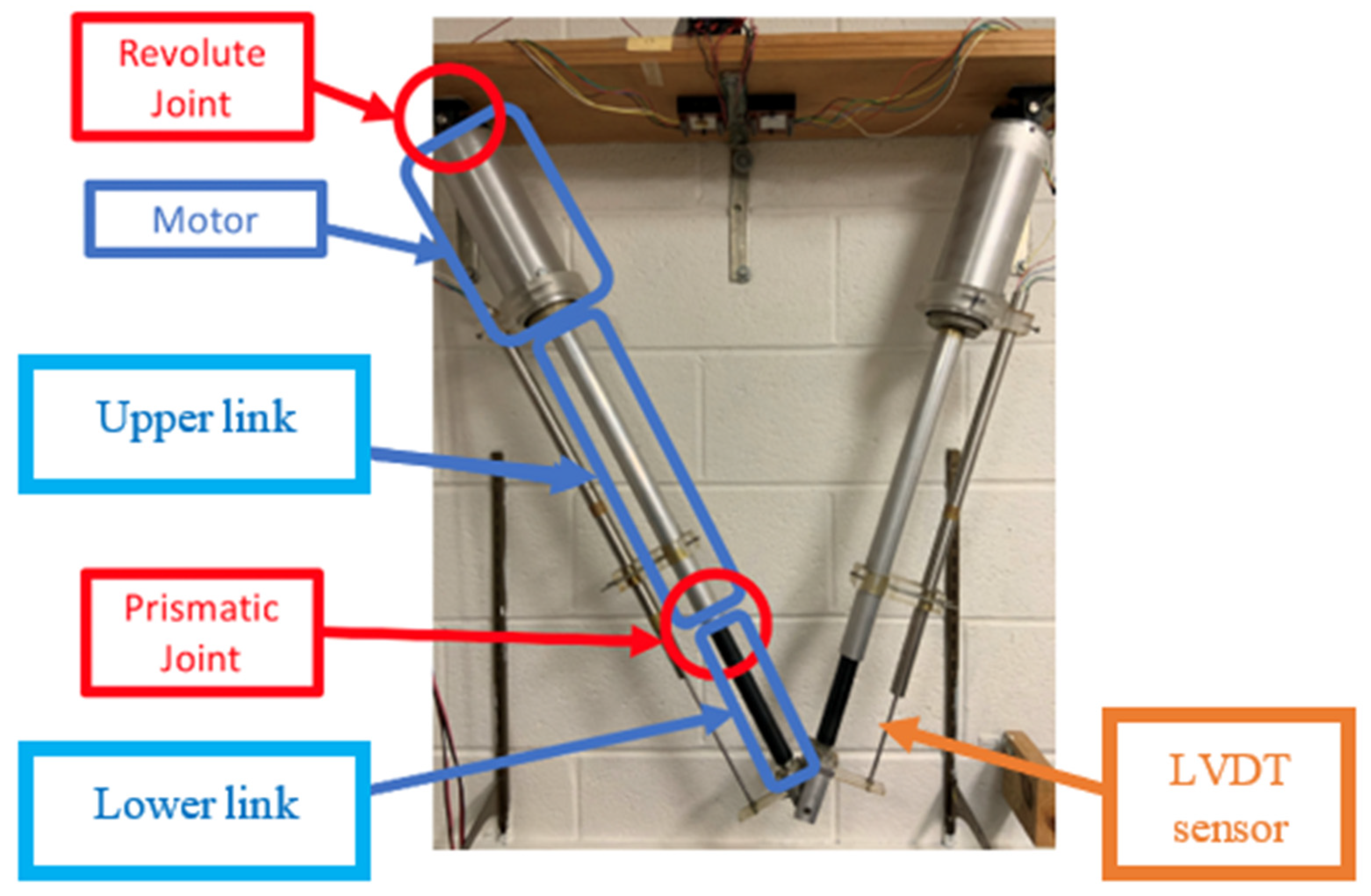
Figure 2.
Closed-loop control system of the manipulator.
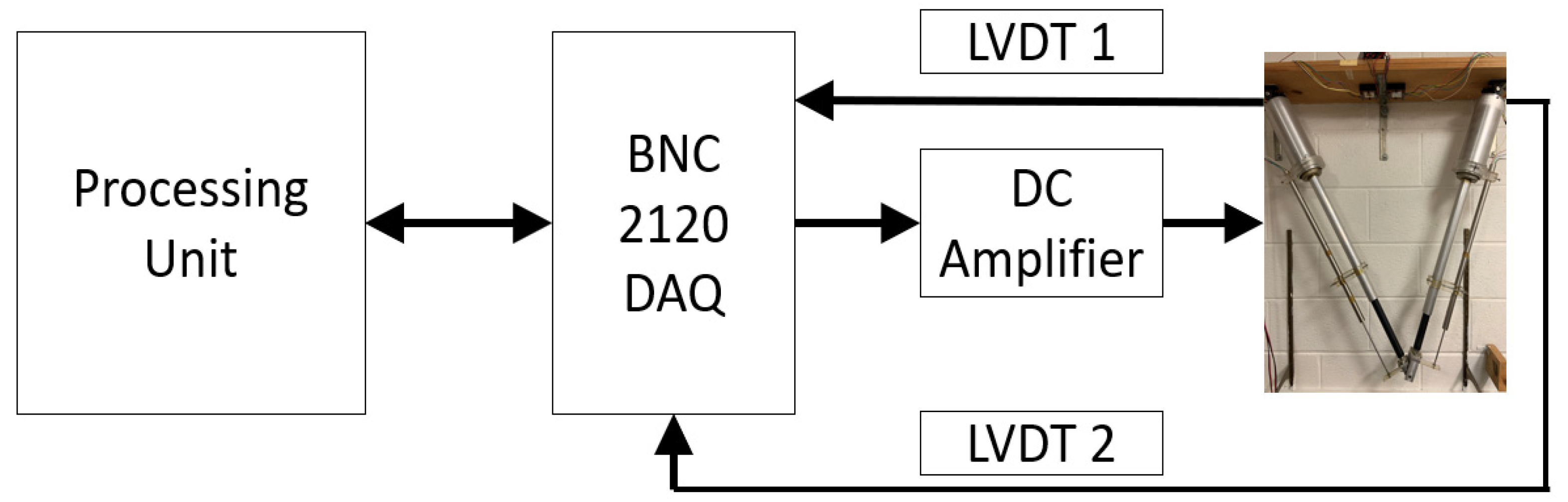
Figure 3.
Frame assignment of the planar 2-DOF CKCM.
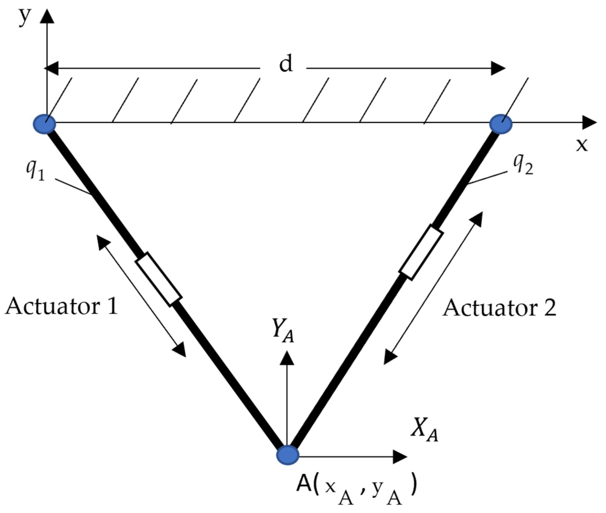
Figure 4.
The Syn-TDE-NFTSMC applied to control the 2-DOF CKCM.
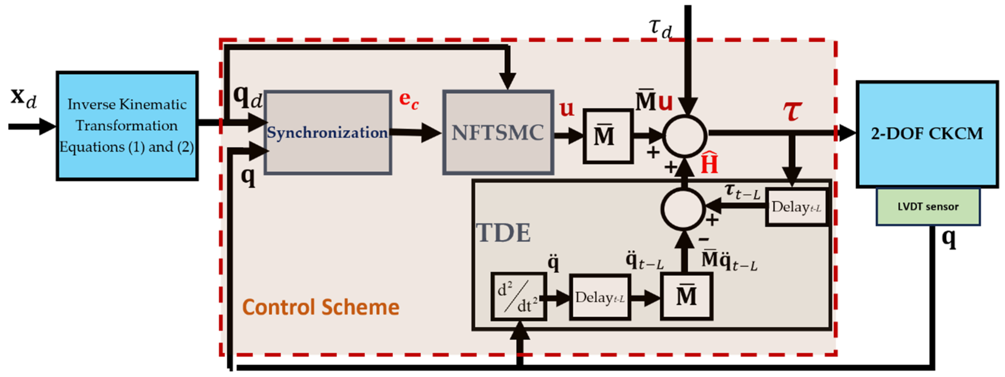
Figure 5.
Trajectory tracking in X-Y plane of control schemes in the experimental study (circular motion).
Figure 5.
Trajectory tracking in X-Y plane of control schemes in the experimental study (circular motion).
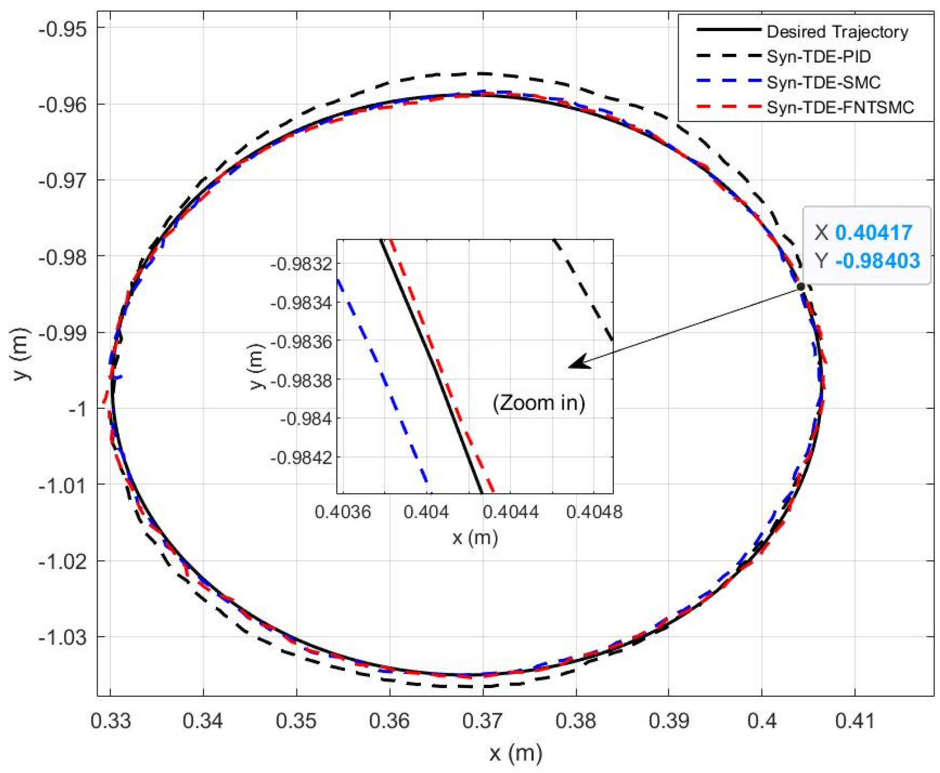
Figure 6.
Time trajectories of tracking errors of the control schemes, of Joint 1 (a) and Joint 2 (b), in the experimental study.
Figure 6.
Time trajectories of tracking errors of the control schemes, of Joint 1 (a) and Joint 2 (b), in the experimental study.
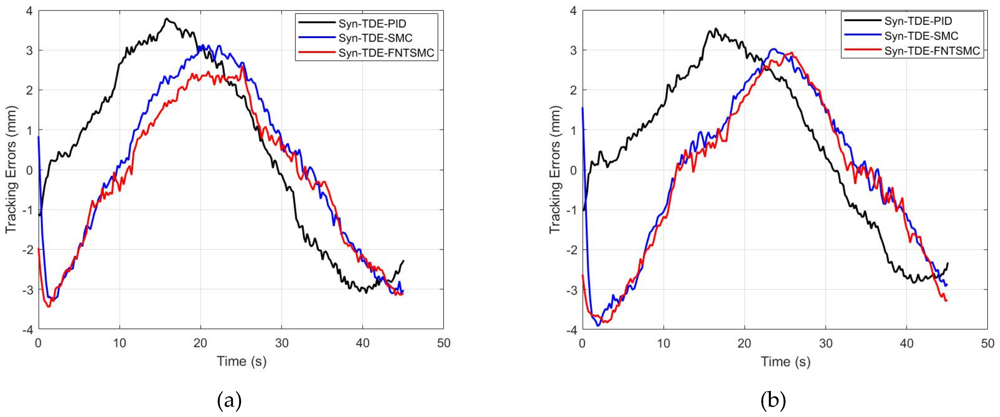
Figure 7.
Time trajectories of synchronization errors and cross coupling errors of the control schemes, of Joint 1 (a) and Joint 2 (b), in the experimental study.
Figure 7.
Time trajectories of synchronization errors and cross coupling errors of the control schemes, of Joint 1 (a) and Joint 2 (b), in the experimental study.
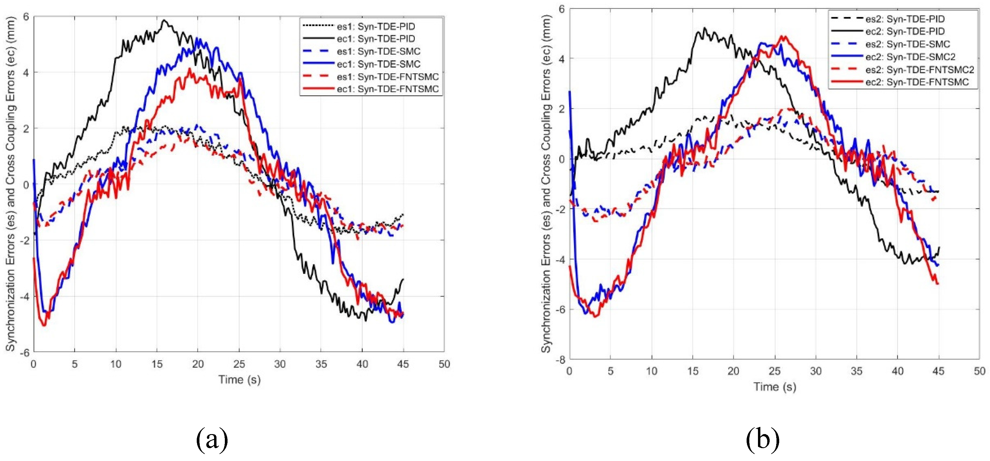
Figure 8.
Time trajectories of estimation errors of control schemes, of Joint 1 (a), (c) and Joint 2 (b), (d), in the experimental study.
Figure 8.
Time trajectories of estimation errors of control schemes, of Joint 1 (a), (c) and Joint 2 (b), (d), in the experimental study.
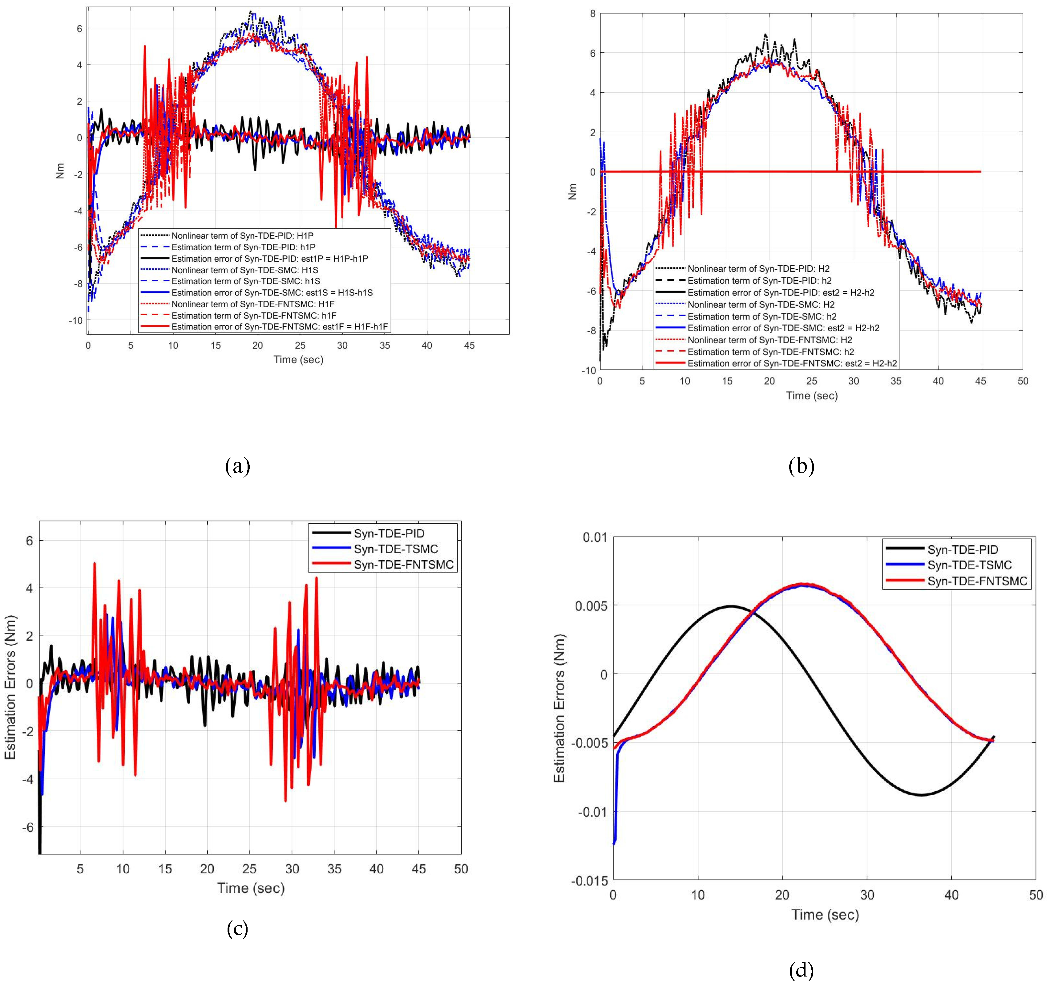
Figure 9.
The control input signals of the control schemes, of Joint 1 (a) and Joint 2 (b), in the experimental study.
Figure 9.
The control input signals of the control schemes, of Joint 1 (a) and Joint 2 (b), in the experimental study.
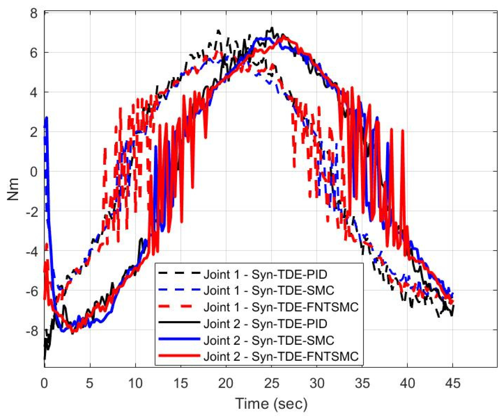

Table 1.
Manipulator parameters and actuators specifications.
| Manipulator Parameters |
Description | Value | Unit |
|---|---|---|---|
| Link’s total mass | 4.91 | kg | |
| Link’s moving part mass | 0.59 | kg | |
| Grounds’ horizontal distance | 0.74 | m | |
| Link’s fixed length | 0.26 | m | |
| g | Gravitational acceleration constant | 9.81 | m/s2 |
| Link’s minimum length | 33 | inch | |
| Link’s maximum length | 48 | inch | |
|
Actuators Specifications |
Description | Value | Unit |
| Motor | Permanent magnet | ||
| Voltage | 24 VDC | VDC | |
| Speed | 3000 RPM | RPM | |
| Diameter | 3 | inch | |
| Stroke | 16 | inch | |
| Gear reduction | 10:1 | ||
| Max velocity | 0.7 | Inch/second |
Table 2.
Specifications of the LVDTs.
| LVDT | Description | Value | Unit |
|---|---|---|---|
| Linear range | ± 7.5 | inch | |
| Linearity | Best fit straight line | ||
| Resolution | Infinite | ||
| Input | ± 14.5 to ± 28 VDC, ± 100 mA | ||
| Output | ± 5 | VDC | |
| Operating temperature range | -67 to 257 | F |
Table 3.
The parameters of the control schemes in experiment study, computed by MATLAB.
| Control Scheme | Control Parameters | |
|---|---|---|
| Syn-TDE-PID | L =s, = diag(0.9, 0.9), = diag(50, 45), = diag(0.4, 0.5), = diag(3, 2.5), = diag(0.5,0.5) | |
| Syn-TDE-SMC | L =s, = diag(0.3, 0.25), = diag(25, 20), = diag(9, 9), = diag(8, 12), = diag(0.5, 0.5) | |
| Syn-TDE-NFTSMC | L =s, = 19, = 11, = 17, =9, = diag(0.3, 0.25), = diag(25, 25), = diag(20, 20), = diag(9, 9), = diag(8, 12), = diag(0.5, 0.5) | |
Table 4.
The absolute average tracking errors (AATE) of the control schemes in the experimental study, computed by MATLAB.
Table 4.
The absolute average tracking errors (AATE) of the control schemes in the experimental study, computed by MATLAB.
| Tracking Errors | Syn-TDE-PID | Syn-TDE-SMC | Syn-TDE-NFTSMC |
|---|---|---|---|
| (mm) | 0.7 | 0.2 | 0.1 |
| (mm) | 0.8 | 0.1 | 0.1 |
Table 5.
The absolute average synchronization errors (AASE) and cross-coupling errors (AACE) of control schemes in the experimental study, computed by MATLAB.
Table 5.
The absolute average synchronization errors (AASE) and cross-coupling errors (AACE) of control schemes in the experimental study, computed by MATLAB.
| Errors | Syn-TDE-PID | Syn-TDE-SMC | Syn-TDE-NFTSMC |
|---|---|---|---|
| (mm) | 0.24 | 0.134 | 0.06 |
| (mm) | 0.32 | 0.19 | 0.15 |
| (mm) | 0.77 | 0.21 | 0.2 |
| (mm) | 0.91 | 0.49 | 0.27 |
Table 6.
The absolute average estimation errors (AAEE) of the Syn-TDE-NFTSMC computed by MATLAB.
| AAEE | Syn-TDE-PID | Syn-TDE-SMC | Syn-TDE-NFTSMC |
|---|---|---|---|
| (Nm) | 0.03 | 0.01 | 0.017 |
| (Nm) | 0.002 | 0.0006 | 0.0006 |
Disclaimer/Publisher’s Note: The statements, opinions and data contained in all publications are solely those of the individual author(s) and contributor(s) and not of MDPI and/or the editor(s). MDPI and/or the editor(s) disclaim responsibility for any injury to people or property resulting from any ideas, methods, instructions or products referred to in the content. |
© 2025 by the authors. Licensee MDPI, Basel, Switzerland. This article is an open access article distributed under the terms and conditions of the Creative Commons Attribution (CC BY) license (http://creativecommons.org/licenses/by/4.0/).
Copyright: This open access article is published under a Creative Commons CC BY 4.0 license, which permit the free download, distribution, and reuse, provided that the author and preprint are cited in any reuse.


