
Submitted:
08 April 2025
Posted:
08 April 2025
You are already at the latest version
Abstract
High penetration of green energy sources presents substantial challenges to grid stability and resilience, primarily due to inherent voltage and frequency variability, which worsened during critical events. This study proposes an integrated framework for stability and resilience enhancement in renewable-dense power grids by designing optimized Universal Droop Controllers (UDCs) tailored for grid-forming operations under high-impact contingencies. The UDC incorporates fault localization functionality via grid-forming inverters embedded with phasor measuring capabilities (phase voltage magnitude and angle) to facilitate real-time fault detection and response, thus augmenting operational reliability. Leveraging integrated solution environments, the developed framework employs numerical optimization routines for resource allocation, load prioritization, economic dispatch of Distributed Energy Resources (DERs), and adaptive network reconfiguration under constrained conditions and during critical events that may necessitate decentralized network configurations in the wake of main grid failures. Validation conducted on the IEEE 123-Node distribution network indicates that the optimized UDC framework achieves superior voltage and frequency regulation compared to conventional droop-based methods, ensuring optimal resource distribution and sustained load support.
Keywords:
Grid-Forming
; Dynamic Optimization
; Fault Localization
; Resilience
; Scalable Integration
; UDC
1. Introduction
The growing integration of distributed energy resources into the power grid is essential in achieving sustainable energy goals but introduces new challenges for grid stability and reliability. DERs, like wind and solar, are not consistent in supply, leading to fluctuations in power generation that can destabilize voltage and frequency levels. As the global energy landscape shifts towards increased decentralization, there is an urgent need for microgrid solutions that can maintain stability and ensure efficient power sharing, even under variable and challenging operating conditions. Traditional control methods, like the widely adopted droop control strategy, provide a basis for decentralized power sharing but have limitations when applied to complex microgrid configurations, particularly in island operations where communication links are minimal or absent. These challenges could be further amplified during extreme events such as hurricanes, flooding, and severe snowstorms that can disrupt main grid connections, necessitating robust, standalone control within microgrids.
Recent advancements in decentralized control strategies have enhanced droop control for microgrids, improving stability and accuracy in power-sharing under variable loads and mismatched impedances. Dual-Frequency-Droop Control (DFDC) addresses these challenges by adjusting power-sharing based on local frequency changes, distributing real, reactive, and harmonic powers precisely without relying on communication links. Additionally, incorporating a dynamic droop-slope-regulator (DDR) mitigates frequency deviations, thus stabilizing distributed generation (DG) units [1,5,7,16,19]. Dynamic Nonlinear Droop Control (DNDC) further improves power-sharing by introducing nonlinear gain adjustments, which hardware testing has validated as effective under heavy loads, outperforming traditional methods [2,6,9,13,21].
Advanced Droop Control (ADC) refines droop control by focusing on reactive power sharing to stabilize voltage levels, especially in islanded microgrids. ADC minimizes reactive power-sharing errors, enhancing renewable integration and balancing voltage under dynamic conditions [3,10,12,17,20]. Similarly, Adaptive Droop Control enables flexible power limits and current adjustments in response to grid disturbances [27]. This adaptive control method improves power quality and prevents overloading by dynamically controlling output, enhancing microgrid resilience against faults. In addition, adaptive hierarchical and consensus-based controls add flexibility by supporting transitions between master-slave and peer-to-peer modes for more effective power-sharing [4,8,15,18].
In grid-connected applications, droop control with current-limiting features helps DGs manage grid fluctuations more effectively. For instance, droop control with floating characteristics stabilizes power and current for inverter-based DGs, handling frequency, and voltage fluctuations to improve power quality [11,14,24]. Offshore wind farms also benefit from droop control through DC link current controllers that enhance stability and operational efficiency, even during faults or varying wind speeds, supporting HVDC transmission integration [6]. Multi-terminal HVDC systems in hybrid AC/DC networks employ adaptive droop techniques to dynamically adjust droop coefficients, thus reducing transient overshoot and enhancing frequency and voltage stability with lead-lag compensators [8,9,25].
In DC microgrids, the Adaptive-Master-Slave (AMS) control strategy uses non-linear droop controllers for seamless control mode transitions and improved power-sharing among voltage source converters (VSCs). This approach ensures coordinated power sharing in multi-terminal systems under changing grid conditions and during contingencies, such as converter outages or shifts in renewable output [7,12,14,15]. Optimization based on multiple objectives, like the Non-dominated Sorting Genetic Algorithm II (NSGA II), has been applied to droop-controlled systems, enhancing voltage regulation, reducing losses, and improving current sharing by using fuzzy logic for control evaluation under conflicting objectives [11,17].
Despite these advancements, challenges persist in decentralized microgrid control. While DFDC [1,5,7] and DNDC [2,9] facilitate communication-free power sharing, achieving precise voltage and frequency control under variable conditions remains difficult. Approaches like ADC [3,12] and adaptive droop control [10,15,18] enhance reactive power sharing and current limiting but still face challenges under extreme conditions, such as fault events or severe weather. Additionally, adaptive droop methods in applications like multi-terminal HVDC [8,14] and DG optimization [11,15] improve efficiency but often lack the dynamic resource management needed for high-stakes, resource-limited conditions. As microgrids evolve, developing robust solutions to address these gaps will be essential.
The proposed work addresses these gaps by introducing a Universal Droop Controller (UDC) in grid-forming mode, designed to enhance both precision and resilience in microgrid control. Unlike prior methods, the UDC integrates GAMS-enabled optimization to maximize load and resource allocation dynamically, ensuring efficient economic dispatch across DERs. Additionally, the UDC incorporates fault localization capabilities by using grid-forming inverters with PMU functionalities, which enable real-time fault detection and response. This approach not only achieves high precision in voltage and frequency control but also supports resilient, autonomous operation during low-frequency, high-impact events, fulfilling key requirements for modern, reliable microgrids as resiliency-enhancing tools [22,26]. Summarized below are the major contributions of the proposed model:
- Achieving accurate voltage/frequency control under varied line conditions.
- Using integrated frameworks for real-time load and resource allocation across multiple DERs.
- Integrating grid-forming inverter with phasor measuring capabilities for real-time network monitoring and fault detection to ensure network stability.
- Maintaining autonomous operation (resilient) during high-impact disruptions (loss of distribution line, loads, and DERs).
- Supporting stable performance in both grid-tied and islanded microgrids.
2. Materials and Methods
Proposed Integrated Framework
The proposed framework is shown in Figure 1, depicting the step-by-step procedures for implementing the integrated solution for grid stability and resilience enhancement.
The optimization model is divided into two parts, namely, (i) MATLAB-Simulink electrical network modeling and (ii) GAMS numerical optimization. A seamless data exchange is established between the electrical network model in Simulink and the GAMS environment through the MATLAB workspace and Excel file. MATLAB-Simulink simulates the power flow of the unbalanced three-phase of the modeled network. The electrical network consists of multiple DERs which are inverter-based with grid-forming GF-UDC controllers. The Simulink model of the electrical network incorporates four UDCs in the grid forming inverters provisioned with systemic parametric variables tuning using an enhanced system transfer function. Figure 2 shows GF-UDC which self-synchronizes with the grid.
The inverter's current-limiting capability is implemented through software control (algorithm), which operates based on the outer and firing control loops. These loops as shown in Figure 3, incorporate GAMS numerical optimization to determine reference values for generating firing signals within the current control block. The load's active and reactive power controls are optimized via GAMS, and provide inputs to the supplementary and outer control loops, effectively constraining the current drawn from the inverters. The active power controller stabilizes the inverter's voltage output by adjusting voltage differences between the grid and inverter. GF-UDC enables voltage and frequency management in island modes, improving power system stability.
On the other hand, GAMS performs the numerical optimization of the simulated electrical network using (a Mixed-Integer Linear Programming) MINLP solver. The MINLP solver handles DER allocation, generation cost minimization, load management, load curtailment, switching operations, and microgrid formation. This is a two-layer operation. The Simulink model calls the optimized DERs and switches from GAMS, streamlining integration and improving network stability and resilience while reducing simulation convergence time.
The integrated solution framework flow chart is presented in Figure 4. The design framework in Figure 4 includes several key components: first, a robust Grid-Forming Inverter (GFI) implemented to enhance grid resilience by minimizing active power oscillations throughout the network. Second, dynamic load control mechanisms are employed to adaptively manage loads based on available resources and system constraints.
Third, microgrid formation is guided by GAMS optimization outputs, aligning with specified objective functions and constraints to ensure resilient operation. Finally, optimized switch control is incorporated to maximize load in cases of main grid failures, distribution line disruptions, or DER losses.
Figure 5 illustrates the typical import of GAMS numerical optimization on the inverter UDC control mechanism in limiting the current drawn from the inverter per unit of time.
Mathematical Modeling
A. Grid-Forming Universal Droop Controller (GFM-UDC)
Designing a Universal Droop Controller (UDC) with both frequency and voltage control is a core task in decentralized control of inverter-based distributed energy resources (DERs), especially in microgrids. UDC is a generalized droop control strategy that regulates both frequency via active power (P) and voltage via reactive power (Q). It combines P–f Droop which adjusts frequency based on active power output and Q–V Droop to adjust voltage based on reactive power. It also includes secondary control loops to eliminate steady-state error and adapt to grid dynamics. To achieve autonomous microgrid inverter control in islanded mode, with grid-forming capability and no communication, there is a need to design local control laws based entirely on local power network measurements. The integration of General Algebraic Modeling System (GAMS) numerical optimization in the control mechanism design as shown in Figure 5 above further enhances the UDC accuracy, resiliency, and robustness in managing several network contingencies. The following equations:
Base Droop Control Equations
1. Frequency Droop Control Law:
2. Voltage Droop Control Law:
where , : nominal/reference frequency and voltage
, : nominal/reference/scheduled active and reactive power
, : Measured output active and reactive power
, : Frequency droop and voltage droop coefficients
Dynamic Modeling of Droop Control with Inverter
The inverter dynamics has been incorporated using first order filter as shown in equations that follows:
A. Active Power Dynamics:
- B. Reactive Power Dynamics:
where , comes from droop control laws in equations (1) and (2). , are active and reactive power time constants.
Secondary Control (PI Controller Restoration)
To eliminate steady-state error, a PI controller restores frequency and voltage to their nominal values:
where , are the adjusted frequency and voltages respectively which serve as input for the inverter’s reference signal generation. , are secondary integral gains. However expanded control model has been deployed for this work as it is intended to handle microgrid inverter control, islanded operation of DERs, autonomous grid-forming inverters, and frequency/voltage regulation without communication protocol [29].
According to Figure 7, there 4-nodal grid forming inverters with UDC capability. The above equations can be re-expressed in state space model form as shown below:
a. Active Power-Frequency Droop
- b. Reactive Power-Voltage Droop
: local inverter frequency (Hz)
: local voltage magnitude (p.u)
, : local active and reactive power output
, : active and reactive power setpoints
, : power system nominal frequency and voltage
, : droop coefficients
- c. Power Dynamics to incorporate inverter filtering and response delay
, : are measured locally from inverter output
, : are locally generated frequency and voltage
, : real-time local active and reactive power measurement
, : time constants of active/reactive control loops
Frequency and Voltage generation (Grid-Forming Capability)
Here the frequency and voltage are used to generate a reference voltage waveform. Each inverter generates a voltage waveform using its own frequency and phase which enables the grid-forming capability of the inverters. Since there is no communication protocol used, only local variables are used in the base droop control laws. These equations are used to model autonomous, decentralized, and resilient microgrid networks with IBRs [30].
- d. Virtual Impedance Incorporation
In order to improve stability in decentralized microgrid operation, virtual impedance () must be included as shown in equation (13):
This helps damp power oscillations and reduce circulating currents between inverters [28,29,31]. Worthy note is the fact that:
- Each inverter behaves as a voltage source.
- Droop control adjusts this voltage source based on local power output.
- The system self-regulates frequency and voltage without coordination.
- Perfect for microgrids, disaster-resilient grids, and remote systems.
Modeling Expanded State-Space Model
Building a state-space model of a single inverter under:
- Frequency and voltage droop control
- Power dynamics (first-order lag)
- Phase angle integration
- Grid-forming sinusoidal output generation
State vector :
where:
: Frequency error integral-
: Voltage error integral-
Updated Droop + Secondary Control Expressions
Frequency controller:
Voltage controller:
Virtual Impedance Injection:
where:
is the inverter output voltage with virtual impedance.
is the inverter-current.
Equation (22) adds passive damping, reduces circulating currents, and improves plug-and-play behavior of the inverter [32].
Coupling the inverter to a load or grid node:
where:
is load impedance.
is the current drawn by the load.
is the grid voltage which is 0 in the islanded mode of operation.
is the line impedance between the inverter and load/grid.
Then compute:
Equations (25) & (26) give real-time power feedback for the inverter based on the actual load/grid. Since the grid operation along with the IBRs operation are nonlinear operations in real life. Equations (15)-(26) can be approximated as Nonlinear State Dynamics and Output Equations as follows:
The inverter’s output:
The GFM-UDC implementation is succinctly described using the set of equations in Figure 6 suitable for grid-forming inverters in microgrids, isolated grids, or systems with high renewable integration. Droop control is governed by the real power droop-frequency and reactive power and droop-voltage laws. E and are the “from-bus-end” and “to-bus-end” voltages, ‘δ ̊’is the phase angle of V, is the coupling reactance, and are the cross-coupling factors for reactive power influence on frequency and voltage values respectively, and are the real and reactive power droop coefficients, and are the angular and nominal frequency of the inverter output, and are the inverter’s active power output and reference, and are the inverter’s reactive power output and reference, and are the inverter’s nominal and output voltage, respectively. The current limiting capacity of the inverter uses the average model, with is the DC link voltage, is the coefficient of the firing period at inverter peak current, T’ is the firing period, ‘t’ is the instantaneous time, ‘L’ & ‘R’ are line inductance & resistance. Adding a virtual impedance improves droop controller stability by emulating the natural impedance in lines, which can help reduce circulating currents among multiple parallel inverters [22].
B. GAMS Optimization Modeling
The objective function is to minimize generation cost, switching, and load curtailment costs as shown in Equation (1).
The generation cost is the fuel cost of the generators, the switching cost is the cost of reconfiguring the network/microgrid, and the load curtailment cost is the penalty imposed due to the unserved load, where is the generator output power at bus i, is a binary decision variable, is the binary switching status of distribution line l, is the curtailed load at load bus d, , , and are cost coefficients of generator i, is the switching operation cost of line l, is the curtailed load cost at bus d.
The power balance, generator, line flow, line capacity, load curtailment, and voltage angle constraints are defined in (32)-(37), respectively.
where is the load on bus d, is a set of generators, is a set of lines, , are the min and max generation limits, is the reactance of line l, are the voltage angles at buses j and k, and .
GAMS numerical optimization implementation in MATLAB Simulink has the following key features:
- Economic dispatch of generators.
- Switch state optimization to minimize the costs of switching operations.
- Dynamic load curtailment to establish network-safe operations.
- Network Constraints enforcement (Bus Voltages, and Angle)
- Optimal Power Flow (OPF) analysis to maintain network stability via power balance constraints enforcement.
- GDXXRW to export optimized switch states to MATLAB for execution in Simulink.
The following are inputs for GAMS network optimization:
- Network total number of buses, Gen_buses, DER_buses, Batt_buses, Switch_lines, Demand response capable buses.
- Active power load (P_load) and Reactive power load (Q_load)
- Voltage magnitude constraint (0.95-1.05 p.u.)
- Base bus voltage (p.u)
- Power flow equations definition based on the distribution flow model.
- Network branch resistance & reactance, maximum generator’s active and reactive powers, maximum DER active and reactive powers.
- SOC-Battery maximum storage capacity (MWh), Battery maximum charging power (MW), Battery maximum discharging power (MW).
- Line failure probability, and demand response savings per MW curtailment ($/MW).
C. Case Study
The framework is validated on a modified IEEE 123-bus distribution network as in Figure 7, consisting of four dynamic loads and 22 DERs distributed across the distribution network.
Four nodal green DERs indicate the locations of the developed UDCs, which are controlled by a unique algorithm that leverages GAMS-optimized results to enable microgrid islanding. The process involves coordinated switching operations and load curtailments applied at specific intervals to initiate microgrid formation and ensure network stability. Additionally, the algorithm manages active inertia power provisioning to prevent system collapse and enhance the controller’s response time. The overall power system network health is checked with an unbalanced three-phase OPF performed on the modified network in GAMS.
3. Results
Simulation Results And Discussions
The results of the simulation are taken from 4-nodal GFM inverters with UDC capability as shown in Figure 7. The microgrids’ frequency levels are stabilized with the synchronized inverters using the proposed integrated framework in Figure 4. A stable frequency, with excellent frequency recovery after each simulated HILF event in the network as in Figure 8,Figure 9,Figure 10 and Figure 11.
The frequency spikes show fault levels that help with fault localization. The measured frequency from inverter-2 highlights two network events: normal and abnormal operating conditions, with the latter caused by intentional disconnections of lines and loads. Figure 8 depicts two zones (A and B), where zone A represents the grid-tied operation mode of the network, and zone B is the islanded mode of operation with HILF events simulated. Zone B shows pronounced frequency spikes that indicate abnormal network conditions. At 25s, a major spike aligns with the disconnection of dynamic loads. At 30s, the line disconnection between nodes 54-57 caused further upward frequency spikes, followed by reconnection after 5s, and additional line adjustments between buses 53-54 from 35s to 40s. These frequency fluctuations indicate high-impact low-frequency (HILF) events, that correlate with spikes observed at inverters 3 and 4 in Figure 8 and Figure 9, confirming faults near them as they exhibit the most pronounced spikes.
The network phase voltages were equally monitored from the four (4) nodal grid-forming inverters with UDC capabilities.
Figure 12, revealed a smooth transition from grid-connected to islanded mode of operation at 20s. There are voltage fluctuations due to load disconnect on the network at 25s, Line disconnection (Between Buses 54-57) occurred at the 30s, and further line disconnection (Between Buses 53-54) at 35s, leading to observed deeps in the network RMS phase voltages measured, and line reconnection at 40s resulting in a slight spike in voltage promptly control by the UDC-inverter.
The measured RMS phase voltages are taken from the four nodal GFM-UDC inverters to validate the global control of the inverters on the network. The following Figure 13, Figure 14 and Figure 15 illustrate the RMS phase voltages measured at inverters 1, 3, and 4, respectively.
Figure 13 illustrates pronounced spikes in phase voltages at 35s and 40s because inverter 1 is very close to the location of line disconnections (simulated HILF events) and reconnections respectively. The UDC inverters restored the network phase voltages quickly back to nominal values after the HILF events. Thus, making the distribution network more resilient to HILF events.
The voltage waveform in Figure 14 indicated a smooth transition from grid-connected to island mode of operation. It followed the waveform pattern in Figure 15 confirming the global visibility of the network state from the UDC-inverters.
Figure 15 further confirms the global visibility of the network and network improved resiliency with UDC-inverter implementation along with GAMS numerical optimization of active network operation which includes switching operations, load curtailments, and HILF event simulations.
In Figure 16, a Y-connected PQ load at node 48 with a peak demand of 210 kW real power and 150 kVAr reactive power. The demand response follows a load curve with managed curtailments. Initially, 100% of the load is supported for 25 seconds. Then, over the next 10 seconds, non-critical loads are shed off, reducing load support to 80%. Between 35 and 45 seconds, further shedding reduces the load to 20%, following the customer’s load profile. Load control is optimized in GAMS, dynamically adjusting weights for resources across various microgrids with different load schedules. The results of other dynamic loads on the distribution network are shown in Figure 17, Figure 18 and Figure 19.
Figure 15 is a Y-connected PQ load-shedding profile on bus 47. Dynamic load 2: 47 Y-PQ: P=105 kW, Q=75 kVAr. The initial load pick-up follows 20%, 100%, and 0%.
Figure 16 is Dynamic load 3 on bus 49: 49 Y-PQ: P=140 kW, Q=95 kVAr. The initial load pick-up follows 20%, 0%, and 100%.
Figure 19 is Dynamic Load 4 at bus 65: 65 D-PQ: P=140 kW, Q=100 kVAr. The initial load pick-up follows 100%, 0%, and 50%. The four dynamic load pick-up percentages are optimized with the GAMS numerical optimization tool. The weights are dynamically allocated to the loads for implementation in the Simulink model of the distribution network shown in Figure 7.
In Figure 20, the RMS active power at the inverter’s output was monitored, where the network operated in grid-connected mode in the first 20s. At 12s, the GFM-UDC is activated to supply 0.3 p.u of network total active power from the DERs still in grid-connected mode of operation, and at the 20s, the microgrid switched to island mode. The grid-forming inverter increased power to support loads, while dynamic loads were shed at 25s. Lines 54-57 were disconnected at 30s and reconnected after 5s, with lines 53- 54 disconnected at 35s and reconnected at 40s. This demonstrates robust active power flow control and stability, with effective power sharing across IBR resources in grid-tie and island modes of operation.
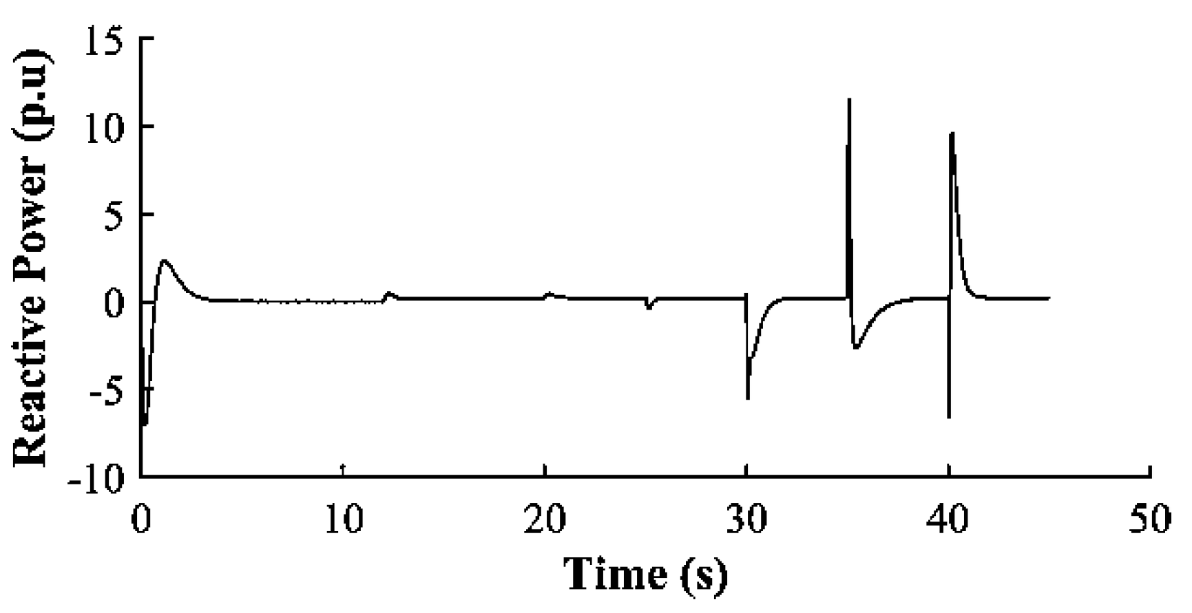
Figure 19 shows the RMS reactive power at DER-4 with significant downward spikes after 30 s, similar to DER-3, which is located near the simulated fault. This indicates that the fault is closer to DERs-3 and 4 when compared to the other DERs, thus allowing easy localization of the fault. The GFM-UDC design improves fault detection and isolation, as shown by spikes at 35s, reflecting line restoration and subsequent disconnection.
The rest of the IBR resources network active and reactive power measurements are shown in Figure 20, Figure 21, Figure 22, Figure 23, Figure 24 and Figure 25. The observed patterns indicated global visibility of the network from each of the GFM-inverters.
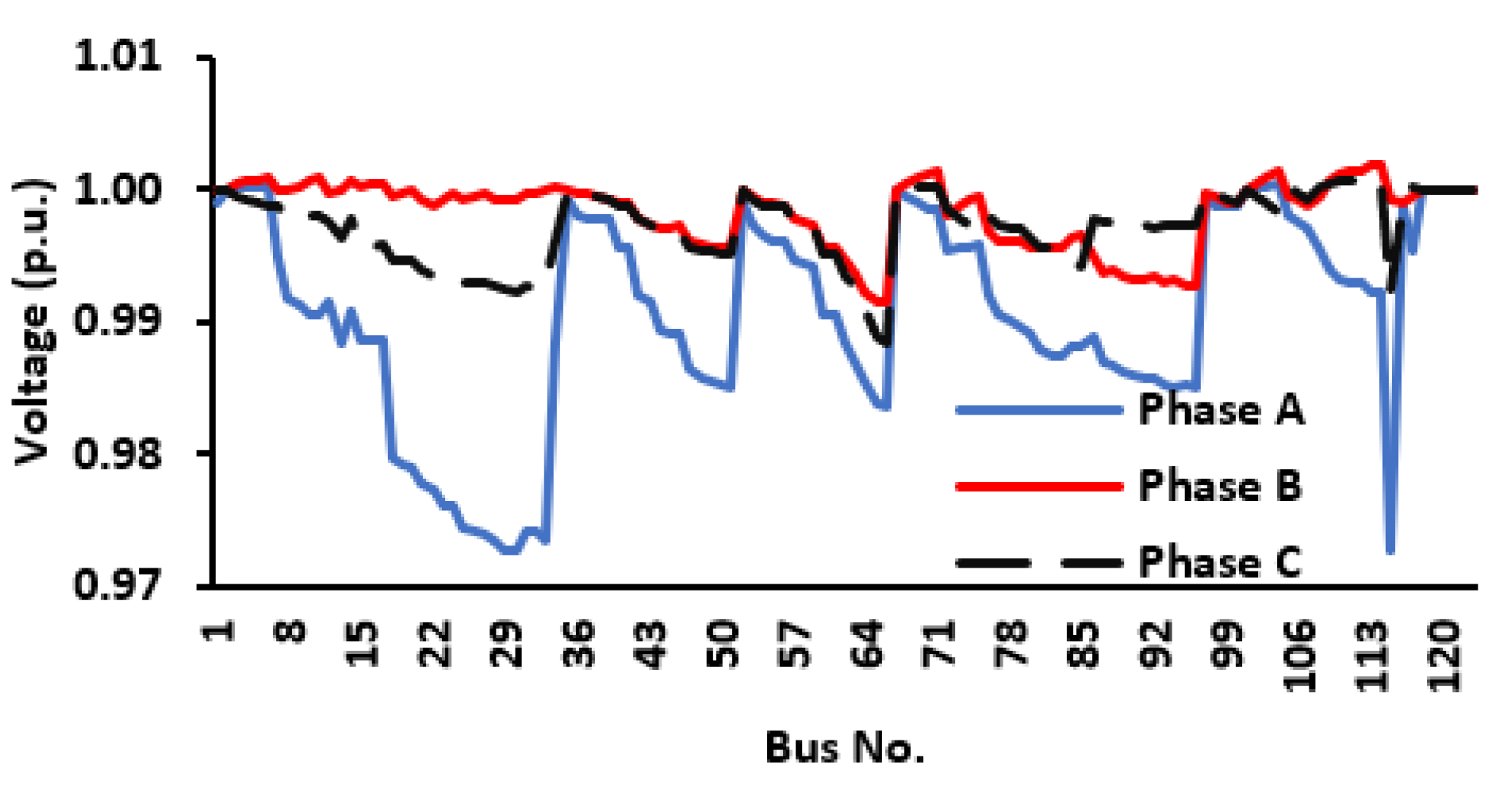
This control approach enhances system resilience and stability, maintaining voltage and frequency during abnormal conditions. The per-phase voltage after optimizing the network operation is shown in Figure 28.
Figure 27.
Inverter-3 Reactive Power (p.u)
4. Discussion
As shown in Figure 20, the optimized unbalanced 3-Φ phase bus voltages are maintained within the required voltage range of 0.95 and 1.05 p.u., validating the effectiveness of the developed framework. Moreso, it is clear that in the grid-tied mode of operation, the active and reactive power output of the GFM inverters is at zero (0) until otherwise set to inject 0.3 p.u of the total active power requirement of the network via IBR resources. This confirms the robust control capability of the designed inverter to handle both modes of operation. The GFM-UDC controllers effectively handle the distribution power network transitioning from grid-tied to the islanded mode of operation, and dynamic microgrid formation in the islanded mode of operation as shown in Figure 6, Figure 7, Figure 8 and Figure 9 (Network frequency profile), 10-13 (Network RMS phase voltages ), 18-25 (Network Active and Reactive Powers). In the face of HILF events discussed earlier, the proposed control mechanism managed the necessary network vitals (frequency and bus voltages) within the acceptable range. Excellent network recovery time after HILF events. Network resiliency is enhanced with the proposed integrated solution.
5. Conclusions
This research introduces a multi-layer distribution network optimization approach, integrating GFM-UDC, GAMS, and MATLAB-Simulink to enhance network stability and resilience under abnormal operating conditions. The results demonstrate efficient voltage and frequency stability in response to simulated HILF events in MATLAB-Simulink. By using GAMS to optimize microgrid formation, switching actions, and dynamic load management, the approach effectively stabilizes the system while leveraging available network resources. Additionally, optimal power flow (OPF) solutions in GAMS achieved cost-effective operation by minimizing load loss during HILF events, ensuring a more stable and reliable distribution network.
Abbreviations
The following abbreviations are used in this manuscript:
| DERs | Distributed Energy Resources |
| GAMS | General Algebraic Modelling System |
| GFL | Grid Following Inverter |
| GFM | Grid Forming Inverter |
| IBR | Inverter Based Resources |
| HILF | High Impact Low Frequency |
| UDC | Universal Droop Controller |
| GDXXRW | GAMS GDX Read Write Command |
| PQ | Active and Reactive Power |
| D-PQ | Delta connected PQ load |
| Y-PQ | Y-Connected PQ load |
References
- R. An, Z. Liu, J. Liu, and B. Liu, "A Comprehensive Solution to Decentralized Coordinative Control of Distributed Generations in Islanded Microgrid Based on Dual-Frequency-Droop," IEEE Transactions on Power Electronics, vol. 37, no. 3, pp. 3583-3597, Mar. 2022.
- H. Tu, H. Yu, and S. Lukic, "Dynamic Nonlinear Droop Control (DNDC): A Novel Primary Control Method for DC Microgrids," IEEE Transactions on Power Electronics, vol. 39, no. 9, pp. 10934-10944, Sept. 2024.
- M. Minetti, A. Rosini, G. B. Denegri, A. Bonfiglio, and R. Procopio, "An Advanced Droop Control Strategy for Reactive Power Assessment in Islanded Microgrids," IEEE Transactions on Power Systems, vol. 37, no. 4, pp. 3014-3023, July 2022.
- A. Saleh, A. Rastegarnia, A. Farzamnia, and K. T. Tze Kin, "Power and Current Limiting Strategy Based on Droop Controller With Floating Characteristic for Grid-Connected Distributed Generations," IEEE Access, vol. 10, pp. 13967-13973, 2022. [CrossRef]
- Z. Zhang, C. Dou, D. Yue, and B. Zhang, "Predictive Voltage Hierarchical Controller Design for Islanded Microgrids Under Limited Communication," IEEE Transactions on Circuits and Systems—I: Regular Papers, vol. 69, no. 2, pp. 933-942, Feb. 2022. [CrossRef]
- A. O. Almeida, P. M. Almeida, and P. G. Barbosa, "Design Methodology for the DC Link Current Controller of a Series-Connected Offshore Wind Farm With a Droop Control Strategy," IEEE Transactions on Industry Applications, vol. 60, no. 2, pp. 3568-3577, Mar./Apr. 2024. [CrossRef]
- X. Xie, X. Quan, Z. Wu, X. Cao, X. Dou, and Q. Hu, "Adaptive Master-Slave Control Strategy for Medium Voltage DC Distribution Systems Based on a Novel Nonlinear Droop Controller," IEEE Transactions on Smart Grid, vol. 12, no. 6, pp. 4765-4772, Nov. 2021.
- Y. Wang, Z. Wang, M. Lei, and F. Qiu, "Analysis and Control of DC Voltage Dynamics Based on a Practical Reduced-Order Model of Droop-Controlled VSC-MTDC System in DC Voltage Control Timescale," IEEE Transactions on Power Delivery, vol. 39, no. 2, pp. 1031-1038, Apr. 2024.
- M. Gu, L. Meegahapola, and K. L. Wong, "Coordinated Voltage and Frequency Control in Hybrid AC/MT-HVDC Power Grids for Stability Improvement," IEEE Transactions on Power Systems, vol. 36, no. 1, pp. 635-644, Jan. 2021.
- S. D. Tavakoli, E. Sánchez-Sánchez, E. Prieto-Araujo, and O. Gomis-Bellmunt, "DC Voltage Droop Control Design for MMC-Based Multiterminal HVDC Grids," IEEE Transactions on Power Delivery, vol. 35, no. 5, pp. 2414-2424, Oct. 2020.
- A. Lasheen, M. E. Ammar, H. H. Zeineldin, M. F. Shaaban, and E. El-Saadany, "Assessing the Impact of Reactive Power Droop on Inverter Based Microgrid Stability," IEEE Transactions on Energy Conversion, vol. 36, no. 3, pp. 2385-2395, Sept. 2021.
- M. N. Ambia, K. Meng, W. Xiao, A. Al-Durra, and Z. Y. Dong, "Adaptive Droop Control of Multi-Terminal HVDC Network for Frequency Regulation and Power Sharing," IEEE Transactions on Power Systems, vol. 36, no. 1, pp. 566-577, Jan. 2021.
- S. Prakash, V. Nougain, and S. Mishra, "Adaptive Droop-Based Control for Active Power Sharing in Autonomous Microgrid for Improved Transient Performance," IEEE Journal of Emerging and Selected Topics in Power Electronics, vol. 9, no. 3, pp. 3010-3020, June 2021.
- Y. Zhang, L. Wang, and W. Li, "Autonomous DC Line Power Flow Regulation Using Adaptive Droop Control in HVDC Grid," IEEE Transactions on Power Delivery, vol. 36, no. 6, pp. 3550-3561, Dec. 2021.
- A. M. Dissanayake and N. C. Ekneligoda, "Multiobjective Optimization of Droop-Controlled Distributed Generators in DC Microgrids," IEEE Transactions on Industrial Informatics, vol. 16, no. 4, pp. 2423-2435, Apr. 2020. [CrossRef]
- F.-J. Lin, K.-H. Tan, C.-F. Chang, M.-Y. Li, and T.-Y. Tseng, "An Improved Droop-Controlled Microgrid Using Intelligent Variable Droop Coefficient Estimation," IEEE Journal of Emerging and Selected Topics in Power Electronics, vol. 12, no. 4, pp. 4128-4140, Aug. 2024.
- N. Ghanbari and S. Bhattacharya, "Adaptive Droop Control Method for Suppressing Circulating Currents in DC Microgrids," IEEE Open Access Journal of Power and Energy, vol. 7, pp. 1-11, Feb. 2020. [CrossRef]
- D.-Y. Shin, D.-H. Kwon, S.-I. Moon, and Y.-T. Yoon, "Real-Time Coordinated Control of a Grid-VSC and ESSs in a DC Distribution System for Total Power Loss Reduction Considering Variable Droop Using Voltage Sensitivities," IEEE Access, vol. 11, pp. 8300-8312, Jan. 2023. [CrossRef]
- M. S. Munir, Y. W. Li, and H. Tian, "Residential distribution system harmonic compensation using priority driven droop controller," IEEE Transactions on Power Electronics, vol. 35, no. 4, pp. 213-223, Apr. 2020.
- X. Wang, J. Zhang, M. Zheng, and L. Ma, "A distributed reactive power sharing approach in microgrids with improved droop control," CSEE Journal of Power and Energy Systems, vol. 7, no. 6, pp. 1238-1245, Nov. 2021.
- Q. C. Zhong, P. L. Nguyen, Z. Ma, and W. Sheng, “Self-synchronized synchronverters: Inverters without a dedicated synchronization unit,” IEEE Trans. Power Electron., vol. 29, no. 2, pp. 617–630, 2014.
- K. Schneider et al., “Evaluating the feasibility to use microgrids as a resiliency resource,” IEEE Trans. Smart Grid, vol. 8, no. 2, pp. 687–696, 2017.
- N. Xue et al., “Dynamic security optimization for N-1 secure operation of power system with 100% non-synchronous generation: First experiences from Hawaii Island,” in Proc. PES Gen. Meeting, Washington DC, USA, 2021.
- W. Du et al., “Modeling of grid-forming and grid-following inverters for dynamic simulation of large-scale distribution systems,” IEEE Trans. Power Del., vol. 36, no. 4, pp. 2035–2045, Aug. 2021.
- K. P. Schneider et al., “Improving primary frequency response to support networked microgrid operations,” IEEE Trans. Power Syst., vol. 34, no. 1, pp. 659–667, Jan. 2019.
- Y. Yao, W. Liu, and R. Jain, "Power System Resilience Evaluation Framework And Metric Review," in IEEE PES Innovative Smart Grid Technologies Conference, New Orleans, 2022.
- Y. Xu, C.-C. Liu, K. P. Schneider, and D. T. Ton, “Placement of remote-controlled switches to enhance distribution system restoration capability,” IEEE Trans. Power Syst., vol. 31, no. 2, pp. 1139–1150, Mar. 2016.
- M. Farrokhabadi, C.A. Ca˜nizares, and K. Bhattacharya, “Power Quality in Microgrids: An Overview,” IEEE Access, vol. 6, pp. 29587–29612, 2018.
- J. He and Y. W. Li, ”An Enhanced Microgrid Load Demand Sharing Strategy,” IEEE Transactions on Power Electronics, vol. 27, no. 9, pp. 3984–3995, 2012.
- E. Olivares et al., ”Trends in Microgrid Control,” IEEE Transactions on Smart Grid, vol. 5, no. 4, pp. 1905–1919, 2014.
- A. Yazdani and R. Iravani, Voltage-Sourced Converters in Power Systems: Modeling, Control, and Applications, IEEE Press, 2010.
- M. Savaghebi et al., ”Secondary Control Scheme for Voltage Unbalance Compensation in an Islanded Droop-Controlled Microgrid,” IEEE Transactions on Smart Grid, vol. 3, no. 2, pp. 797–807, 2012.
Figure 1.
Proposed Operation Framework.
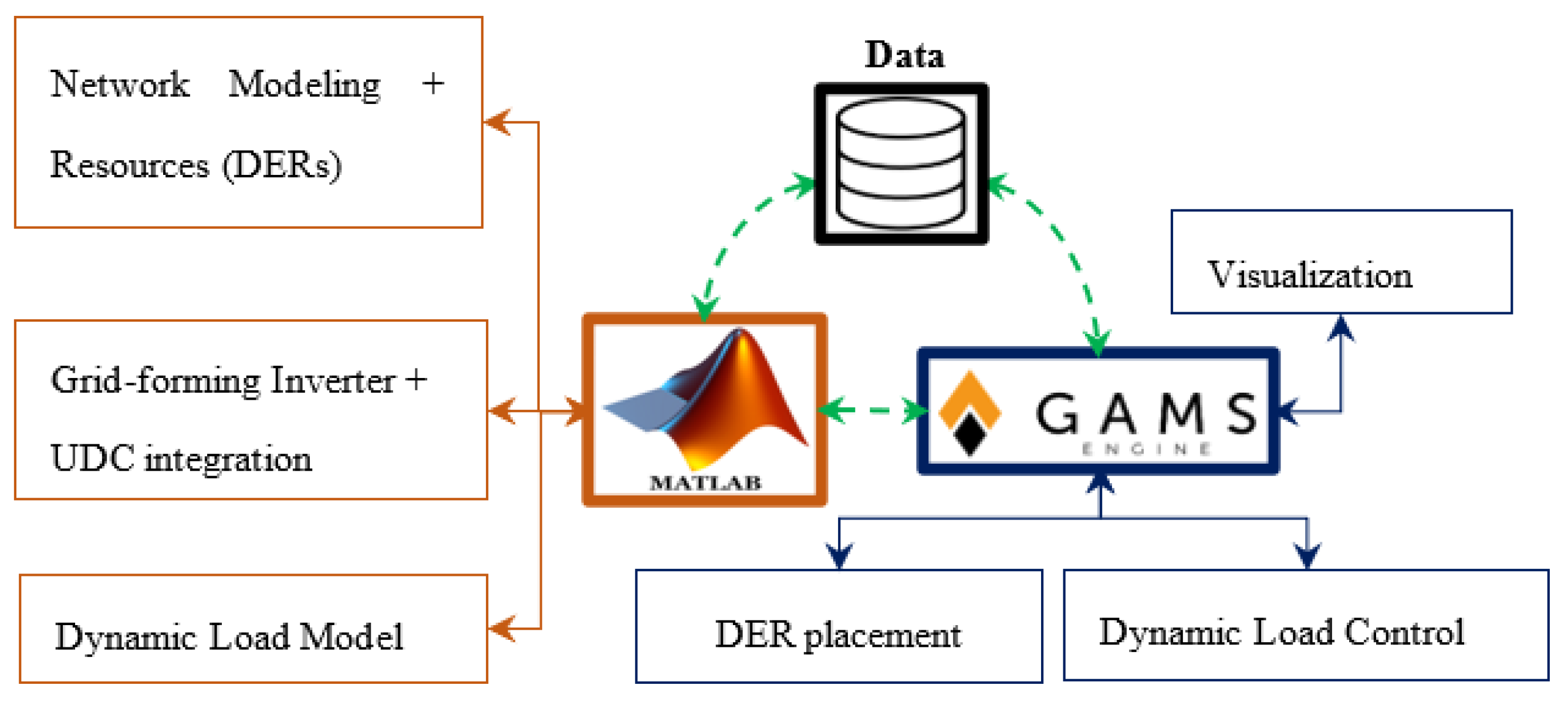
Figure 2.
Grid-Forming Inverter Controller Incorporation to network.
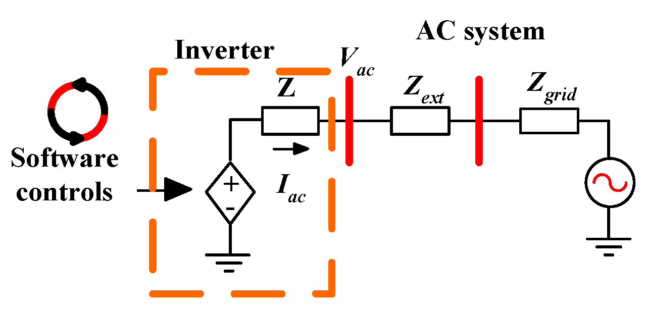
Figure 3.
The Inverter firing time order.
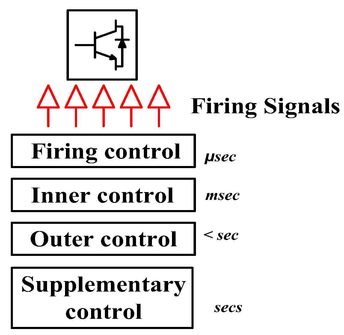
Figure 4.
Proposed Integrated Framework Flowchart.
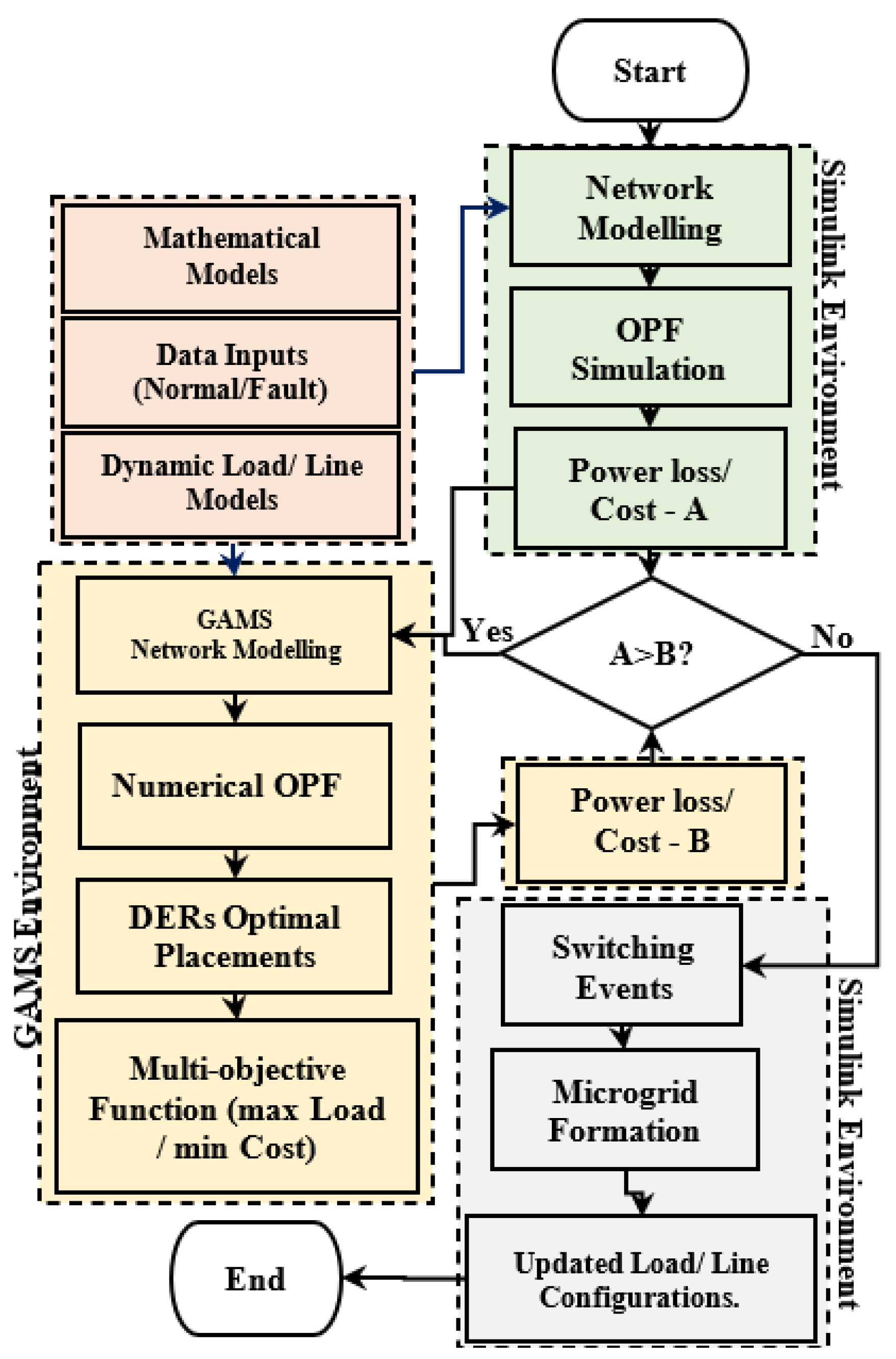
Figure 5.
Overall implementation of UDC inverter on the network.
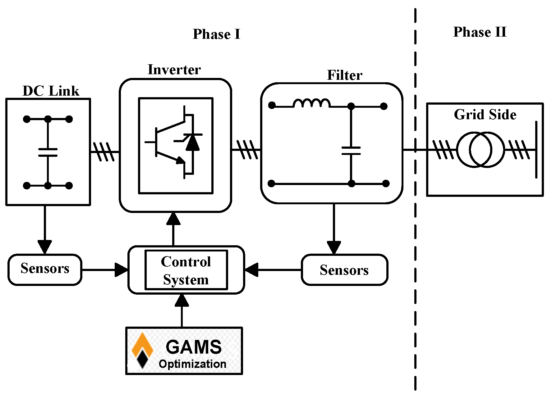
Figure 6.
Line Diagram of GF-UDC Implementation
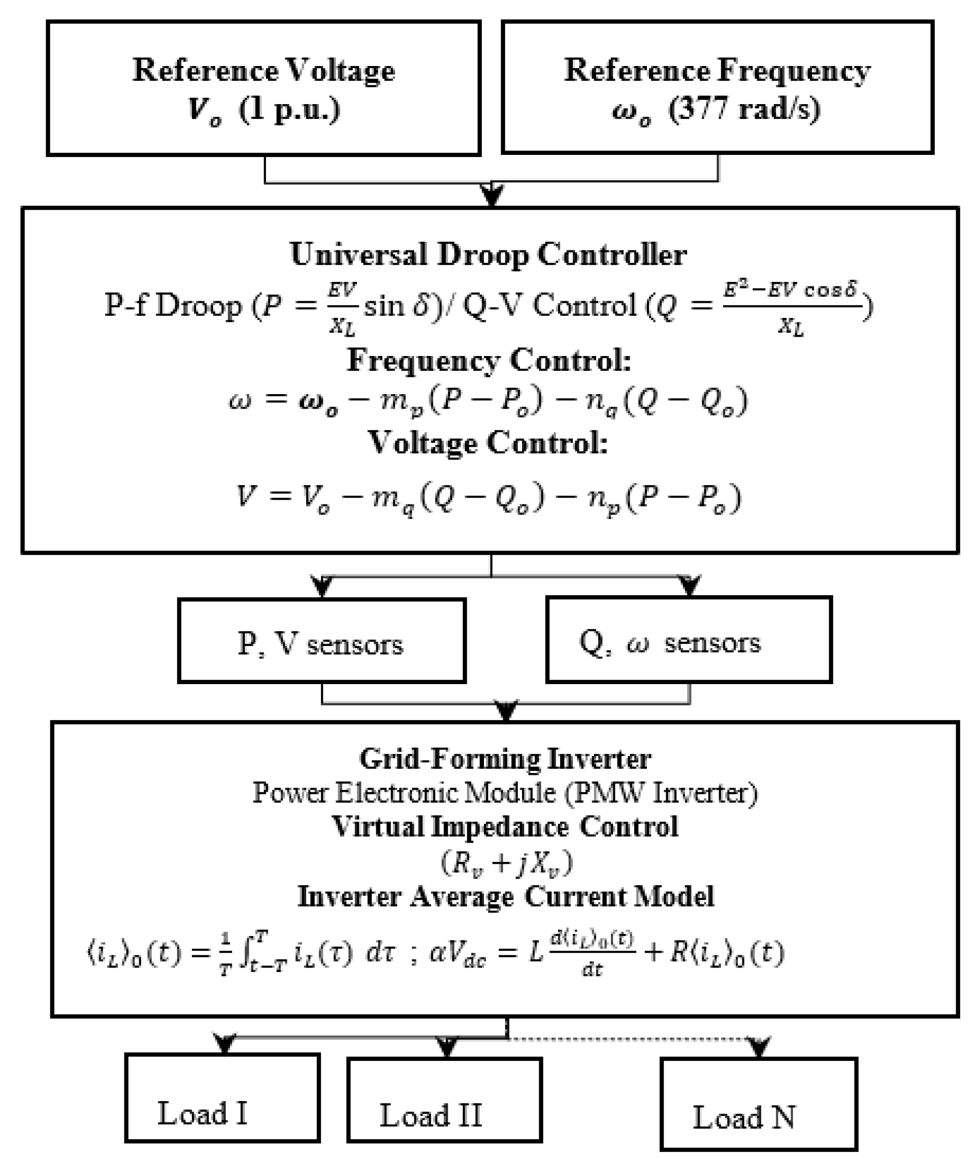
Figure 7.
Modified IEEE 123 Bus System.
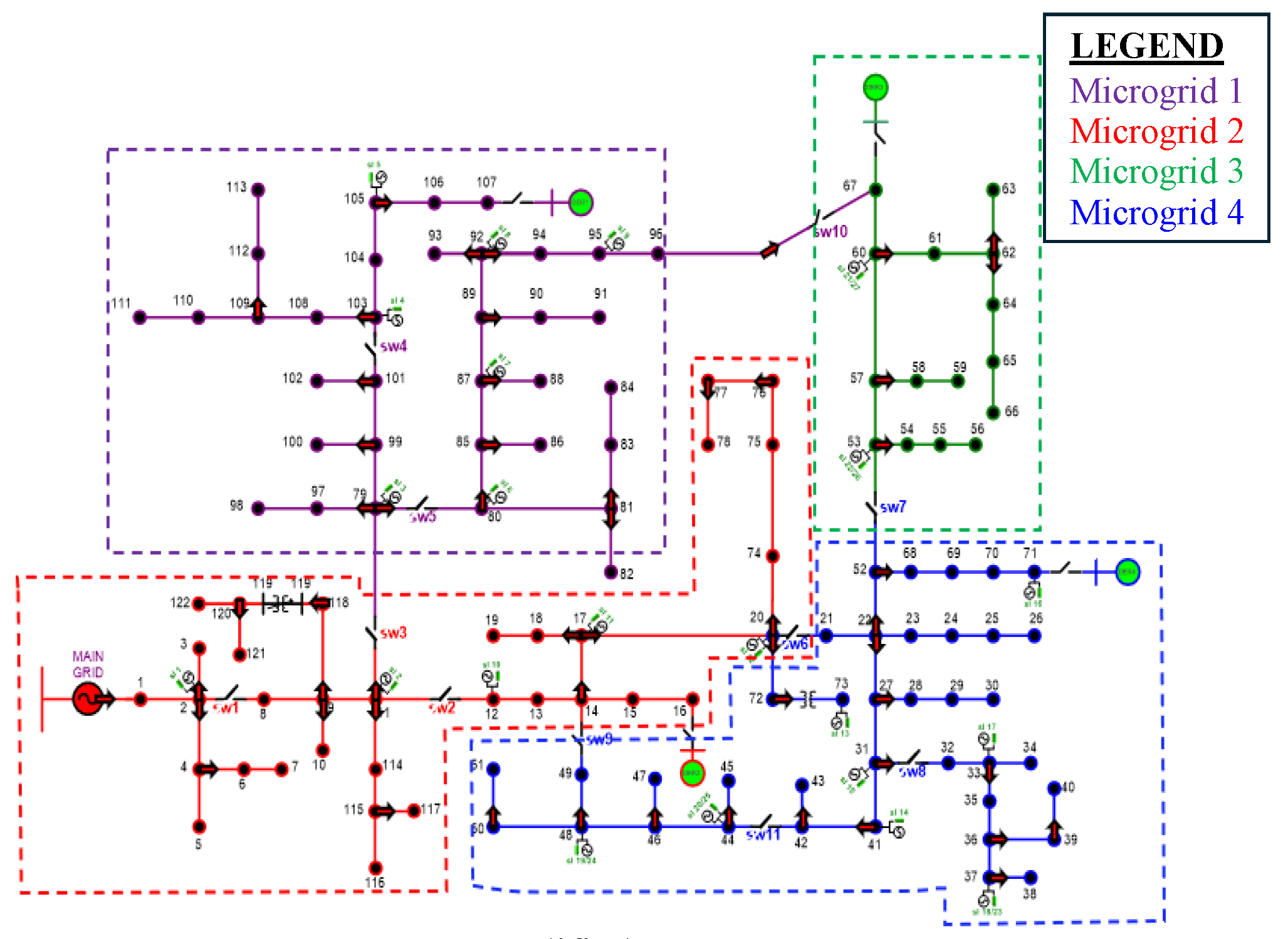
Figure 8.
Inverter-2 Grid Frequency (Hz).
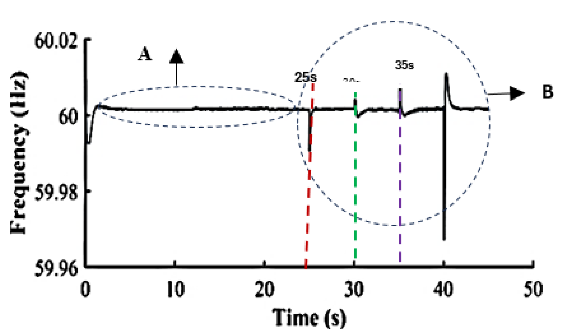
Figure 9.
Inverter-1 Grid Frequency (Hz).
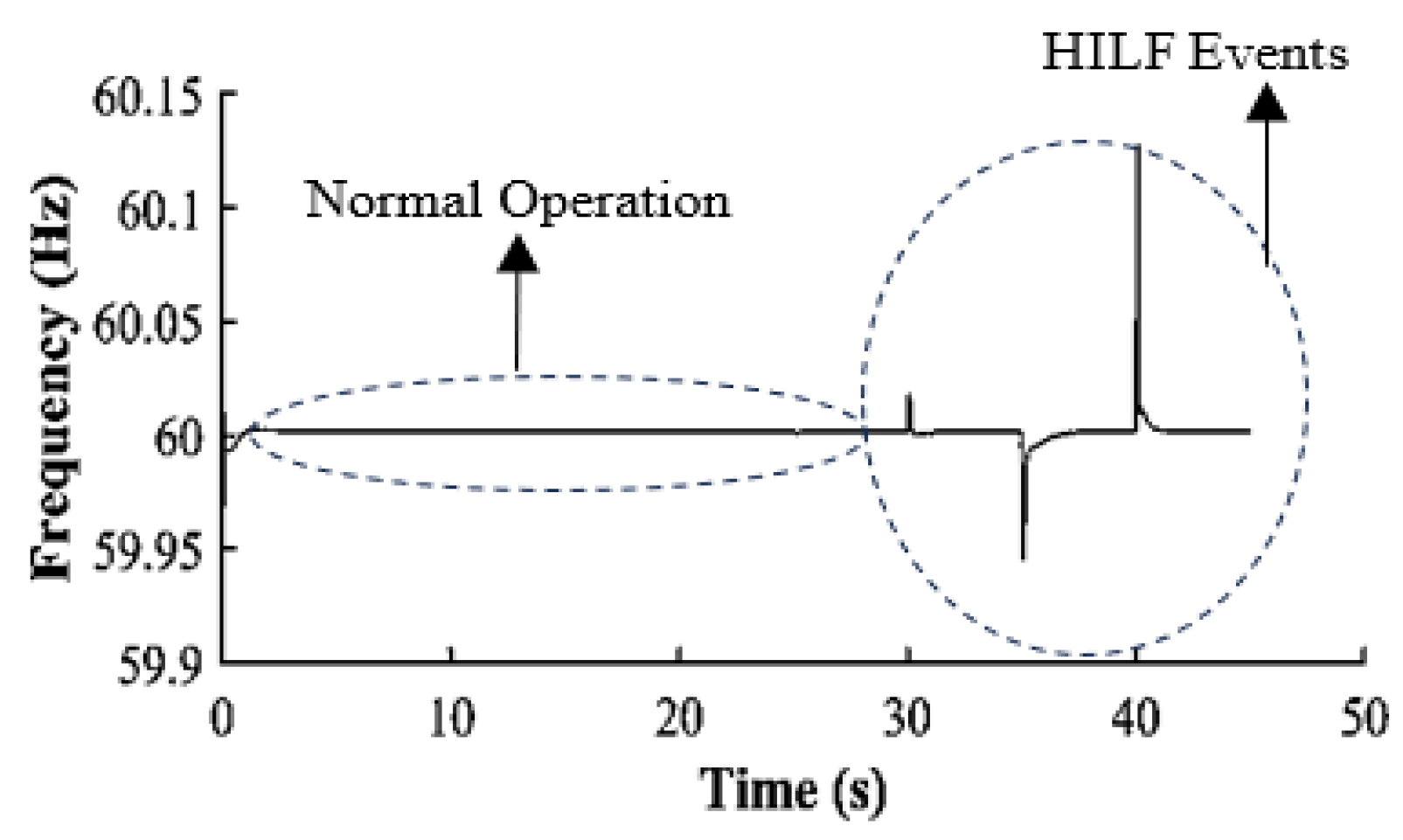
Figure 10.
Inverter-3 Frequency (Hz).
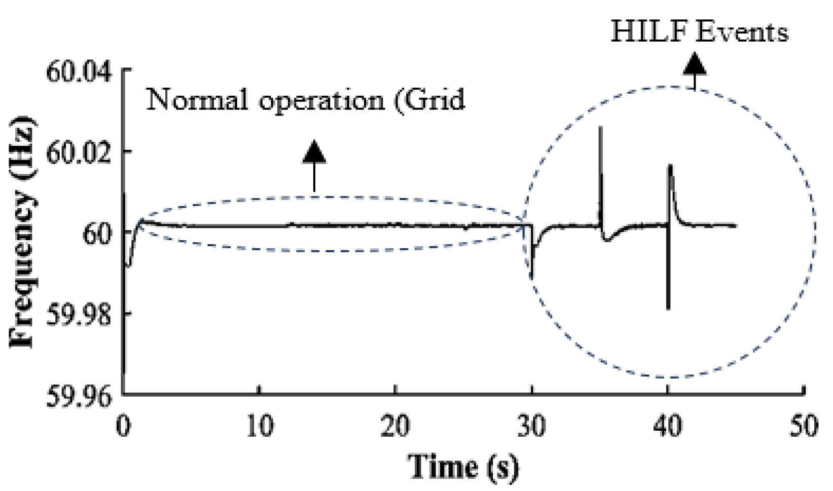
Figure 11.
Inverter-4 Frequency (Hz).
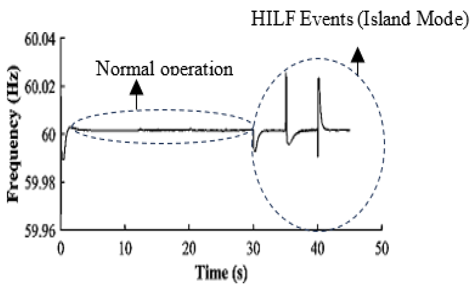
Figure 12.
Phase Voltage RMS values at inverter 2.
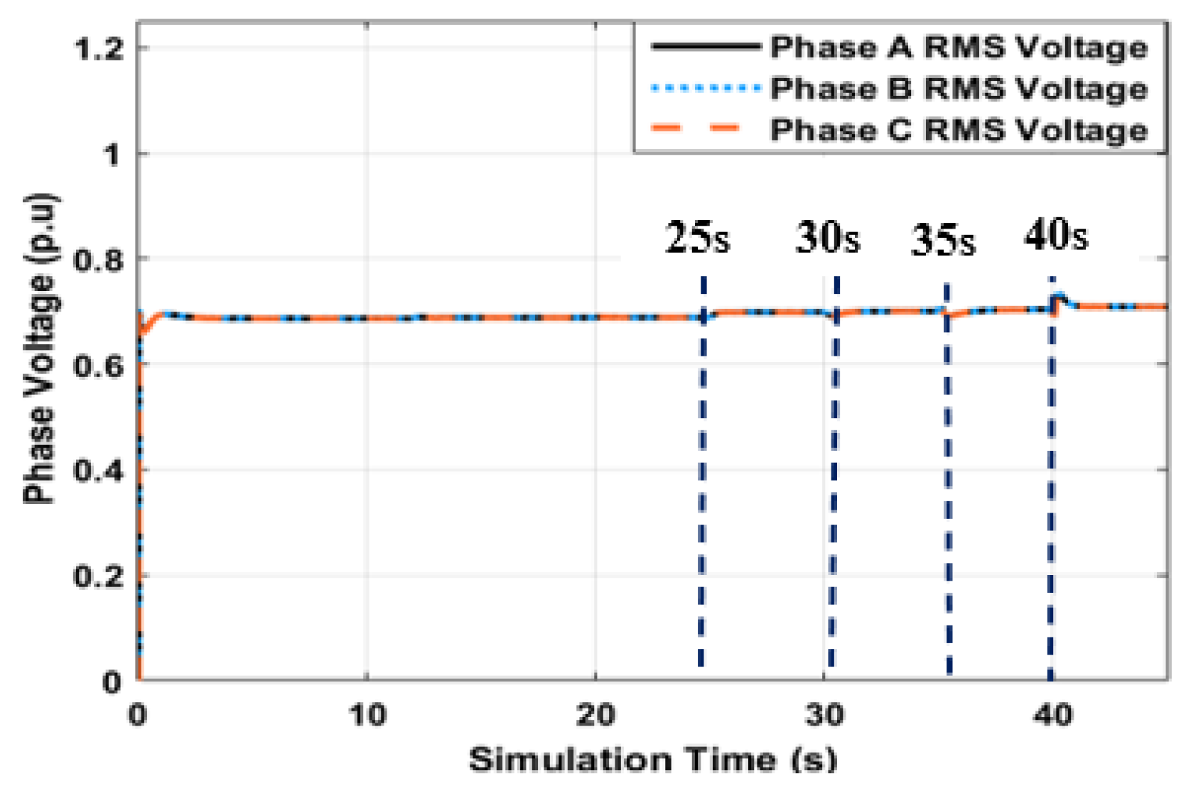
Figure 13.
Phase Voltage RMS values at inverter 1.
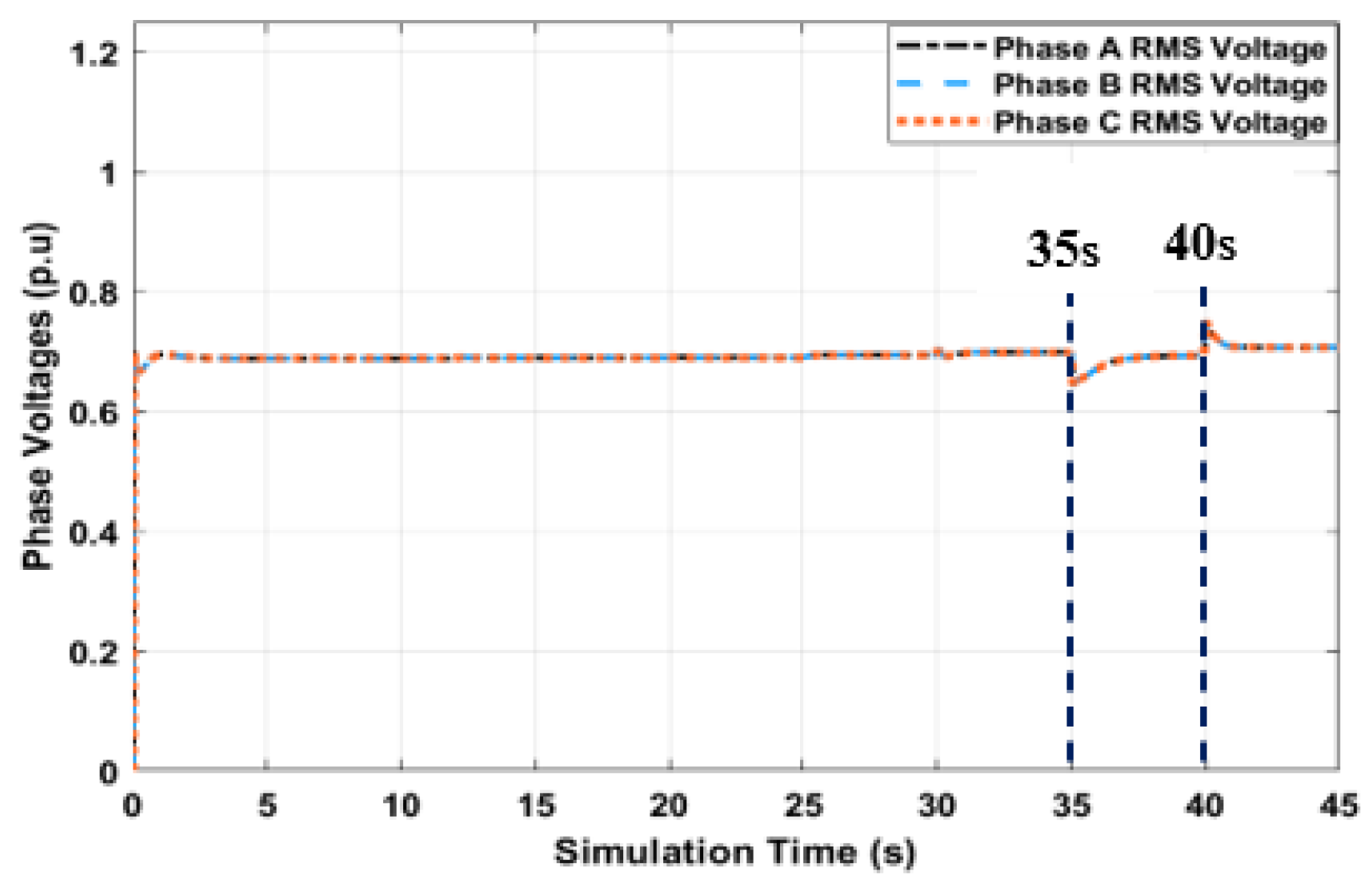
Figure 14.
Phase Voltage RMS values at inverter 3.
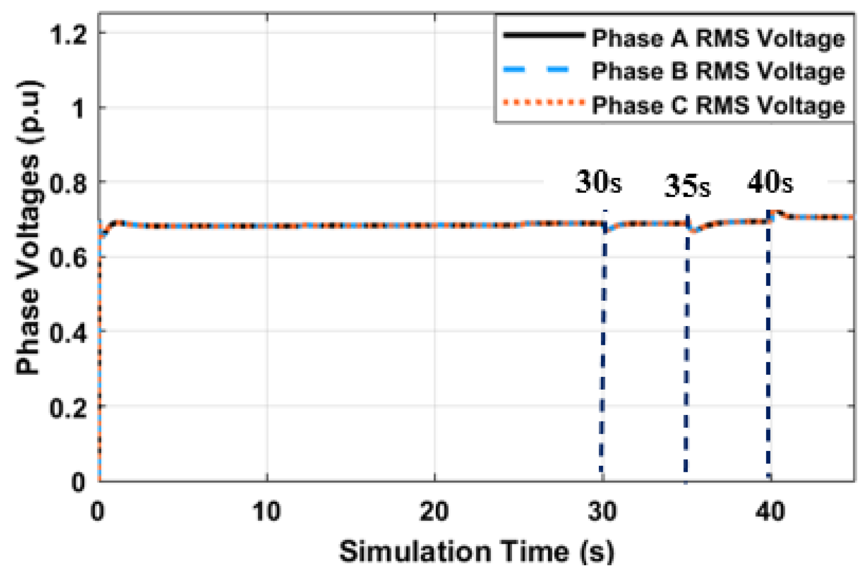
Figure 15.
Phase Voltage RMS values at inverter 4.
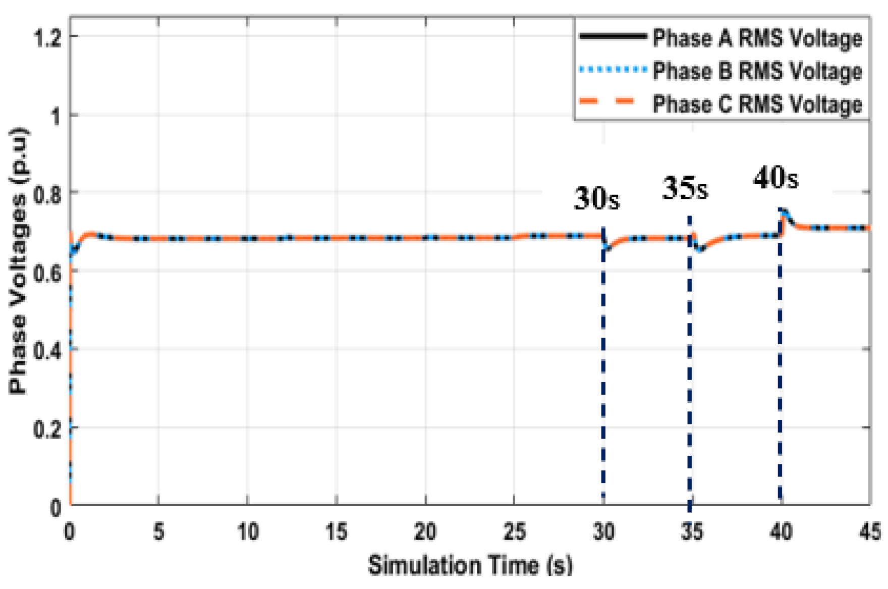
Figure 16.
Dynamic Load Control (Bus 48 Y-PQ).
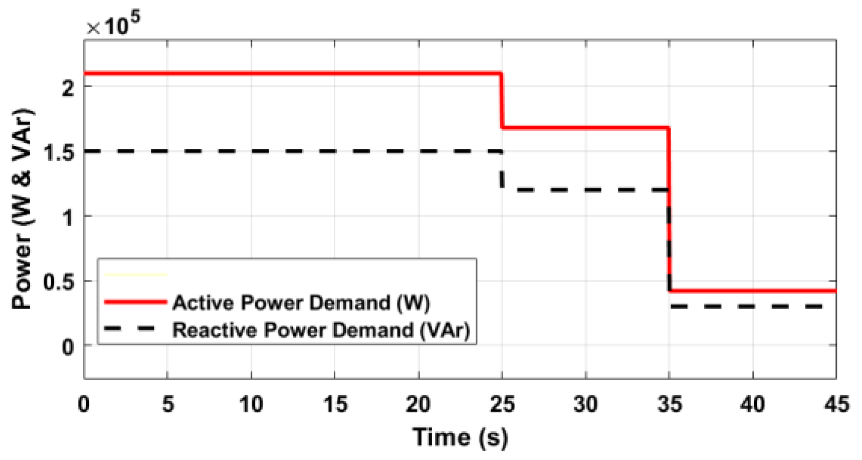
Figure 17.
Dynamic Load Control (Bus 47 Y-PQ).
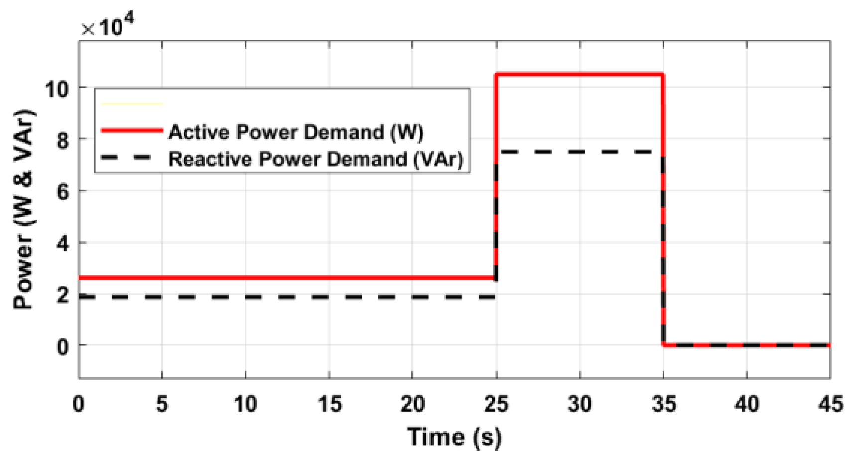
Figure 18.
Dynamic Load Control (Bus 49 Y-PQ).
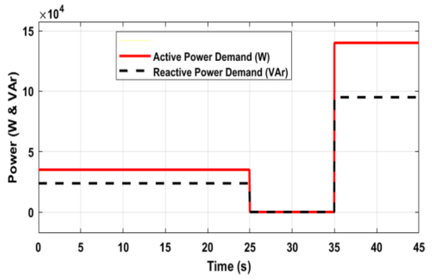
Figure 19.
Dynamic Load Control (Bus 49 D-PQ).
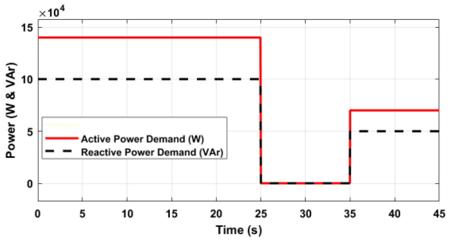
Figure 20.
Inverter-4 Active Power (p.u)
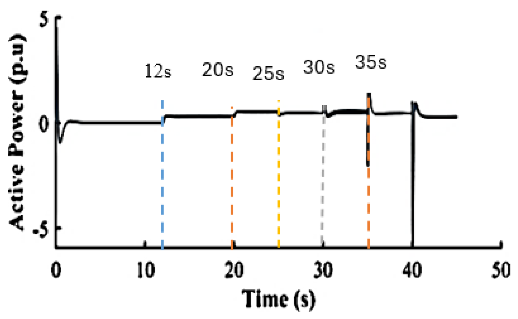
Figure 21.
Inverter-4 Reactive Power (p.u)
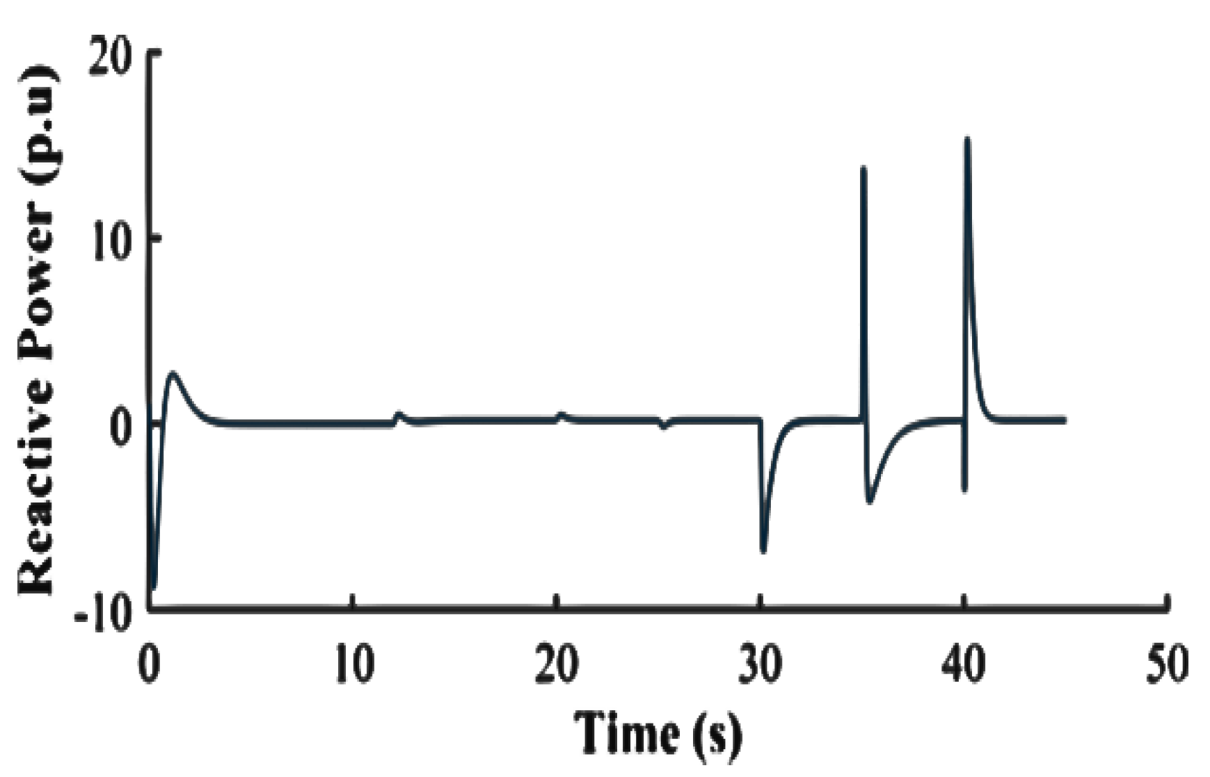
Figure 22.
Inverter-1 Active Power (p.u)
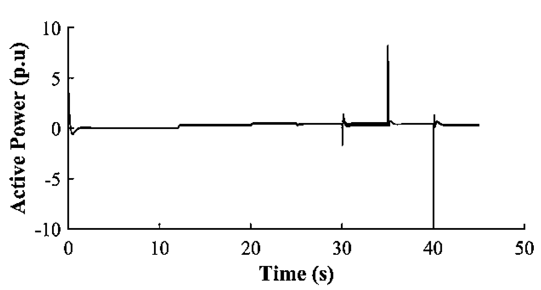
Figure 23.
Inverter-1 Reactive Power (p.u)
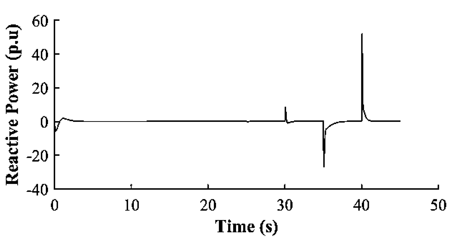
Figure 24.
Inverter-2 Active Power (p.u)
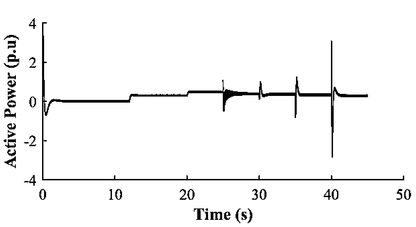
Figure 25.
Inverter-1 Reactive Power (p.u)
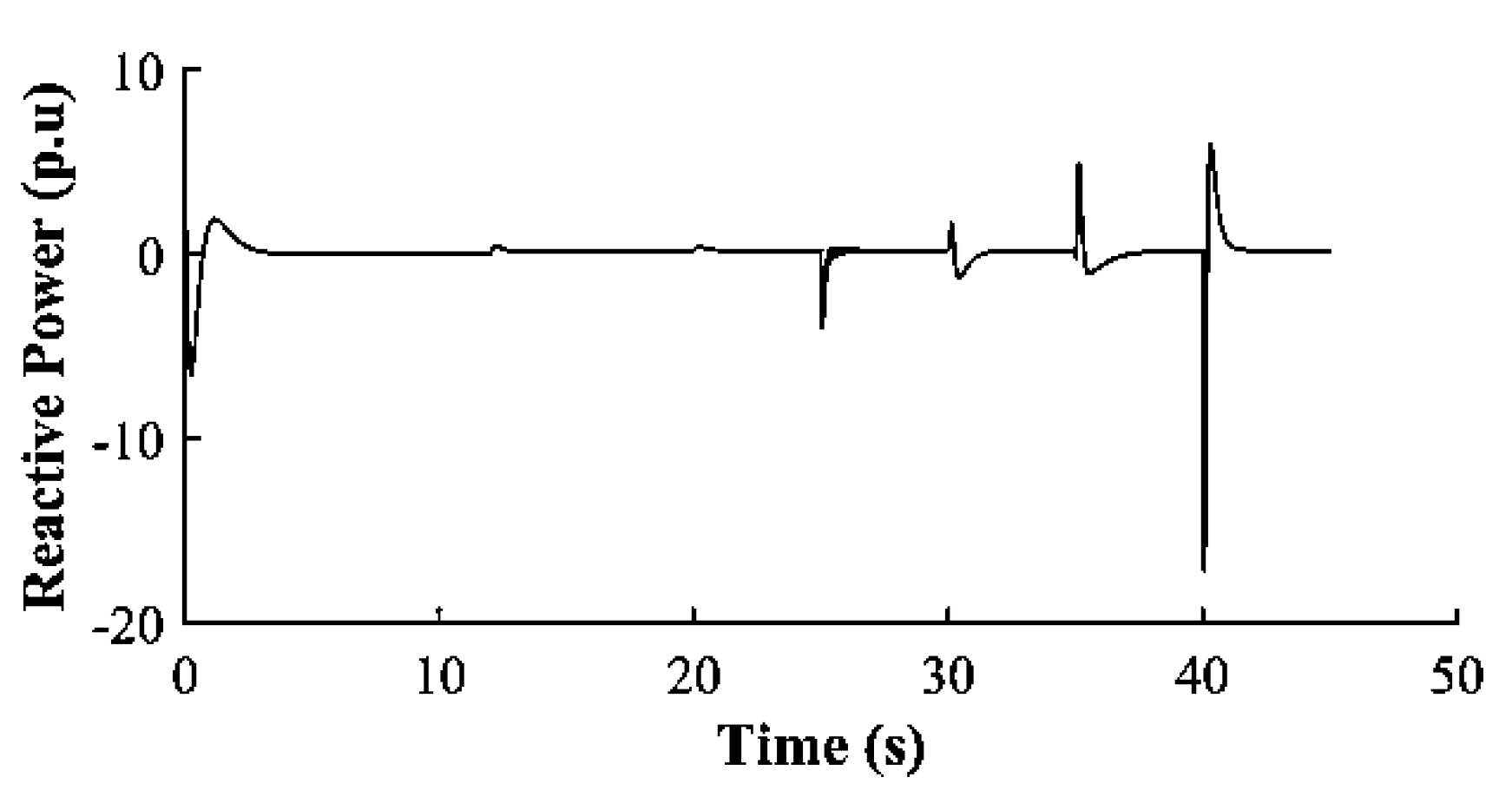
Figure 26.
Inverter-3 Active Power (p.u)
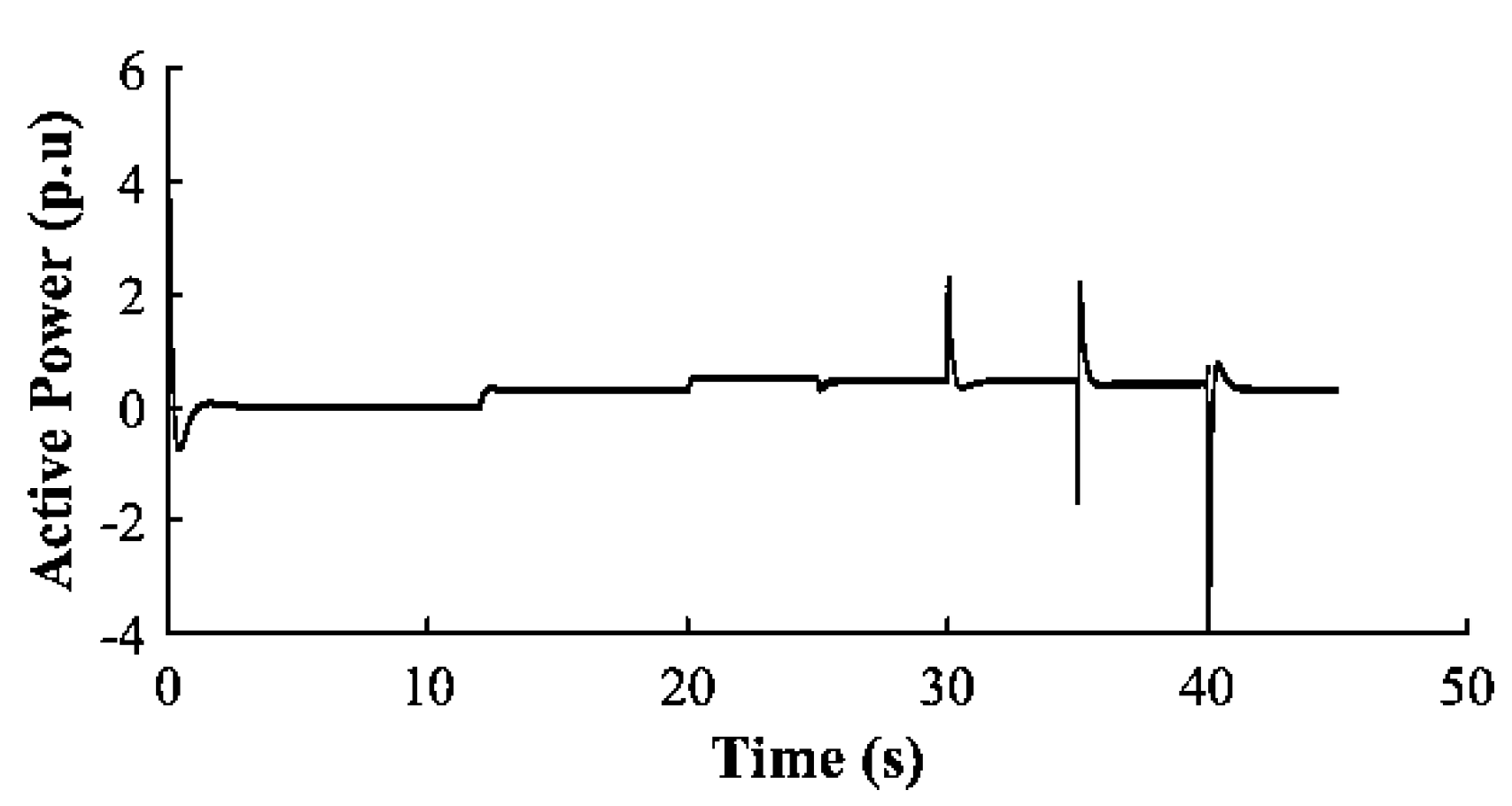
Figure 28.
Optimized unbalanced three-phase voltage.
Disclaimer/Publisher’s Note: The statements, opinions and data contained in all publications are solely those of the individual author(s) and contributor(s) and not of MDPI and/or the editor(s). MDPI and/or the editor(s) disclaim responsibility for any injury to people or property resulting from any ideas, methods, instructions or products referred to in the content. |
© 2025 by the authors. Licensee MDPI, Basel, Switzerland. This article is an open access article distributed under the terms and conditions of the Creative Commons Attribution (CC BY) license (http://creativecommons.org/licenses/by/4.0/).
Copyright: This open access article is published under a Creative Commons CC BY 4.0 license, which permit the free download, distribution, and reuse, provided that the author and preprint are cited in any reuse.


