
Submitted:
28 March 2025
Posted:
31 March 2025
You are already at the latest version
Abstract
The limited build space of additive manufacturing (AM) machines constrains the maximum size of AM components, while manufacturing costs rise with geometric complexity. To enhance value and overcome size limitations, it can be more efficient to join non-AM and AM components to meet the requirements by means of a hybrid structure. Adhesive bonding is particularly suitable for such joints, as it imposes no constraints on the joining surface´s geometry or the adherend´s material. To ensure structural integrity, it is conceivable to exploit the design freedom underlying AM processes by optimizing the topology of the AM component to stress the adhesive layer homogenously. This study explores the feasibility of this concept using the example of an axially loaded single-lap tubular joint between a carbon fiber reinforced composite tube and an additively manufactured laser-based powder bed fusion aluminum alloy sleeve. The sleeve topology was optimized using the finite element method, achieving a 75 %P reduction in adhesive stress increase compared to a non-optimized sleeve. Due to the pronounced ductility of the two-component epoxy-based adhesive, the static bond strength remained unaffected, whereas fatigue life significantly improved. The findings demonstrate the feasibility of leveraging AM design freedom to enhance adhesive joint performance, providing a promising approach for hybrid structures in lightweight applications.
Keywords:
additive manufacturing
; powder bed fusion
; adhesive bonding
; topology optimization
; bond strength
; finite element method
; composite
1. Introduction
Additive manufacturing (AM) processes, such as laser-based powder bed fusion of metals (PBF-LB/M), enable the realization of complex topologies with variable stiffness and internal cavities, which can significantly enhance structural performance [1,2]. However, with increasing geometric complexity, manufacturing costs rise due to the need for additional support structures, rework, and longer production times [3]. Additionally, the limited build space of AM machines constrains the maximum size of a single AM component manufacturable, affecting the feasibility of AM for various applications. To overcome these limitations and reduce manufacturing costs, part separation and subsequent joining of AM subcomponents can be an effective strategy [4,5]. Moreover, the freedom of design underlying AM processes is often needed only in specific regions of a structure. Thus, it can make sense to enhance the structure with non-AM components (i.e. fiber-reinforced composites) by means of a hybrid structure [6,7]. Adhesive bonding is a particularly promising joining technology in this context, as it adds minimal weight and does not restrict the geometry of the joining surfaces or the material of the adherends [8,9,10,11].
To ensure structural integrity, the adhesive joint design plays a crucial role [12,13]. This entails ensuring a sufficiently large adhesive surface area and preferably subjecting the adhesive to shear rather than peel stress (tensile stress perpendicular to the adhesive surface) [12,13,14]. Adhesive joint designs can roughly be categorized into butt joints and lap joints. In butt joints the substrates are simply joined end-to-end at their front surfaces. Due to the comparably small adhesive surface area and the occurrence of large peel stresses, this design is less common in structural applications [15]. In lap joints, the joining surfaces of the substrates are overlapping and therefore providing an arbitrarily large adhesive surface area. Disadvantageous is the additional weight due to the material overlap, as well as the eccentric load application in combination with finite adherend stiffness, which is causing pronounced adhesive stress increases at the overlap ends [16]. As the stress increases initiate failure [17], it is conceivable to increase the bearable load of the joint (bond strength) while maintaining a constant adhesive surface area by homogenizing the adhesive stress distribution and shifting the adhesive stress state towards pure shear through optimizing the geometry of the adherends.
Finite element (FE)-based genetic algorithm (GA) and topology optimization (TOP) approaches have already been applied to enhance bond strength in rectangular [18,19] and tubular [12] single-lap joints (SLJ´s). These studies employ either a continuum mechanics approach with energy- or stress-based failure criteria or a fracture mechanics approach utilizing cohesive zone modeling (CZM) and a damage-based failure criterion. While previous TOP procedures neglect adhesive plasticity in the corresponding constitutive response, an essential factor in strength assessment [20,21], the GA approach accounts for debonding through a traction-separation law and considers adhesive plasticity via a Johnson-Cook plasticity model, making it the most suitable method in terms of strength assessment and failure prediction. However, this approach is computationally expensive and, as a result, fails to leverage the extensive design flexibility offered by additive manufacturing. Although all procedures demonstrate significant potential for increased bond strength, previous studies lack experimental validation.
Therefore, in this study, a computationally efficient solid isotropic material with penalization (SIMP) algorithm [22] and implicit FE analysis are used to optimize the topology of an additively manufactured laser-based powder bed fusion aluminum alloy AlSi10Mg (PBF-LB/M/AlSi10Mg) sleeve, which is part of an axially loaded single-lap tubular joint (SLTJ) adhesively bonded to an inner carbon fiber reinforced composite (CFRC) tube using a highly ductile two-component (2C) structural adhesive based on epoxy resin (3M Scotch-Weld, DP490). The joint is modeled using a continuum mechanics approach, where adhesive plasticity is accounted for by means of a multilinear elastoplastic material model. To increase the bond strength of the joint, the element density of the PBF-LB/AlSi10Mg sleeve is iteratively adjusted to achieve homogenous adhesive shear stress. The optimum sleeve topology found is redesigned considering manufacturing constraints of the PBF-LB/M additive manufacturing process. To quantify the resulting adhesive stress state, non-linear FE analysis is conducted at different tensile loads with tubular joints featuring optimum, redesigned and non-optimized cylindrical reference sleeves. Subsequently redesigned and cylindrical reference sleeves are manufactured and adhesively bonded to CFRC tubes to experimentally quantify the difference in bond strength by means of static tensile and fatigue testing.
2. Materials and Methods
The axially loaded SLTJ subjected to implicit FE-based TOP comprises an inner adherent, which is a roll-wrapped unidirectional CFRC tube having an outer diameter of and a wall thickness of , as well as an outer adherent, which is an additively manufactured PBF-LB/M/AlSi10Mg sleeve having an inner diameter of . The adherends are joined by an interstitial layer of a two-component epoxy-based (2C-Epoxy) structural adhesive (3M Scotch-Weld, DP490) having a thickness of . The outer adherent is divided into the non-design space (NDS) having an outer diameter of and the design space (DS) having an outer diameter of . During the optimization process, the element density of the DS is the variable to be altered to meet the objective function of the SIMP optimization (Figure 1).
The overlap between the inner and outer adherend is , leading to a adhesive surface area of . To minimize computational effort, only a segment of the rotationally symmetric joint was discretized using CHEXA20 second-order solid elements (outer adherend and adhesive), respectively CQUAD8 second-order shell elements (inner adherend), which were assigned to a cylindrical analysis coordinate system. To enforce rotational symmetry, the azimuthal displacement of elemental nodes at the symmetry faces was constrained to . The adhesive layer is represented by eight elements in the radial direction () and 120 elements in the longitudinal direction (), resulting in element edge lengths of (radially) and (longitudinally). The average element edge length in the DS of the AlSi10Mg Sleeve results to . The contacts between adjacent components are modelled continuously by merging coincident elemental nodes at the component interfaces. To replicate the boundary conditions of the pursuing tensile tests, rigid clamping is applied by fixing all degrees of freedom at nodes on the top surface of the clamping shoulder (bolt head seating, see Figure 2) and a longitudinal tensile force is introduced at nodes on the top surface of the CFRC tube using a one-dimensional rigid body element (1D-RBE). As part of the TOP process, the longitudinal tensile force was set to . Given the reduced adhesive surface area of of the segment considered, this results in a nominal adhesive shear stress of .
The material parameters utilized for modeling the structural mechanical behavior of the components are shown in Table 1.
As the von Mises equivalent stress in the AlSi10Mg sleeve must not exceed the yield strength of , it is reasonable to define linear-elastic material parameters only. Neglecting the build-direction-induced anisotropy intrinsic to the PBF-LB/M process is permissible, as the material parameters defined in Table 1 were determined from vertically oriented tensile samples [23], consistent with the intended build direction of the AlSi10Mg sleeves. The CFRC tube exhibits linear-elastic material behavior up to the tensile strength of [24]. Considering a nominal tensile stress in the CFRC tube of (corresponding to , the constitutive response of the CFRC tube is fully characterized by specifying linear-elastic material parameters. The CFRC tube laminate is composed of ten stacked unidirectional plies having a thickness of each. The fibers extend parallel to the longitudinal (z) direction of the tube. By modeling the laminate ply-based, the layer stack and fiber orientation can be represented by single shell elements. This requires specifying the orthotropic material parameters of a single unidirectional ply, along with the orientation and order of the plies. The material parameters provided in Table 1 are referring to a unidirectional ply with high tenacity (HT) fibers and a fiber content of according to [24]. Since the 2C-Epoxy adhesive exhibits non-linear stress-strain behavior far below the ultimate strength of , pure consideration of elasticity is insufficient for structural-mechanical analysis [20,21]. To account for the adhesive´s plasticity, in [25] a multilinear elastoplastic material model is employed. In doing so, the technical stress-strain curve obtained from static tensile tests using adhesive bulk samples according to [26] is approximated using multiple regression lines and the deflection points of the locally linearized stress-strain curve serve as input parameters for the material model. By assuming elastic and plastic isotropy, the structural-mechanical behavior of the 2C-Epoxy adhesive is fully characterized by additionally specifying the shear modulus G, which was determined through torsion testing of butt-bonded hollow cylinders [25].
The optimization function considered by the SIMP algorithm is defined by an optimization target and optimization constraints [22]. As FE-based analysis of an axially loaded SLTJ using CZM shows that bonding failure, following a bi-linear traction-separation law, correlates with the maximum first principal stress adjacent to the bonding interface [12], the optimization target is set to minimize the first principal stress within the adhesive component. Considering a reference value for the first principal stress of , pure adhesive shear and minimum peel stress is aimed for. Optimization constraints regarding the aluminum sleeve (DS and NDS) include a maximum von Mises equivalent stress of and a mass reduction of in the DS. To meet the objective function criteria, the SIMP algorithm iteratively adjusts the element density () of each individual element in the DS of the PBF-LB/AlSi10Mg sleeve. The can vary in the range of , where corresponds to no material and corresponds to solid material. Since the penalization parameter of the SIMP algorithm is set to , intermediate element densities () are penalized, promoting a clear distinction between solid and void regions. The optimization process converges when the relative change in the objective function between two consecutive iterations falls below the threshold of .
To quantify the resulting adhesive stress state, the optimum sleeve topology is FE analyzed at tensile loads of and , corresponding to nominal adhesive shear stresses of (nonlinear) and (linear) and the first principal stress is evaluated for all 120 elements representing the adhesive layer along the overlap (-direction) at adhesive mid-thickness (in the fifth of eight element rows representing the adhesive layer in positive -direction). For classification, this result is contrasted with the course of the first principal stress induced by a redesigned sleeve and a non-optimized cylindrical reference sleeve having an outer diameter of . The redesigned sleeve is based on the optimum topology but considering manufacturing constraints related to the PBF-LB/M process. The redesign was generated based on the contour plot of optimum ED using computer-aided design (CAD) software (Dassault Systèmes, CATIA V5). In doing so, the contours depicted where resketched (neglected) and abstracted to comply with a minimum overhang angle of and a minimum wall thickness of [2,27]. Subsequently the sketch was rotated over an angle of to form a solid body, which served as a basis for the ensuing FE analysis. Both the FE-based stress analyses and the TOP procedure were conducted using commercially available FE software (Altair Engineering, HyperWorks 2021) with the OptiStruct solver.
To experimentally quantify the bond strength of redesigned and reference sleeves, static tensile and fatigue tests were performed using a total of bonded tensile samples. These include four redesigned and four cylindrical reference sleeves for conducting static tensile tests, as well as eight redesigned sleeves and eight cylindrical reference sleeves for conducting fatigue tests. The sleeves were manufactured using a DMG MORI LASERTEC 30 SLM 2nd Generation PBF-LB/M additive manufacturing machine. The associated manufacturing parameters are depicted in Table 2.
Commercially available AlSi10Mg powder (EN-AC 43000 as specified in [28]) with a particle size between and was used throughout. To suppress influences on the surface roughness caused by varying component orientation and to ensure consistency with the material parameters provided in Table 1, the AlSi10Mg sleeves were manufactured vertically oriented (longitudinal axis perpendicular to the build plate). The redesigned sleeve features radial slots with a slot opening angle of to facilitate the removal of residual powder from the internal cavities. The maximum and minimum inner diameters of the sleeves were determined to and by optical measurement using a 3D laser scanning microscope (Keyence, VK-X 3000). Commercially available roll-wrapped unidirectional CFRC tubes with nominal dimensions of were used as inner adherents. They offer a HT fiber content of and a ground outer surface finish. The tubes maximum and minimum inner diameters were determined to and using a digital outside micrometer (Mitutoyo, Absolute Digimatic 2). A 2C-Epoxy structural adhesive (3M Scotch-Weld, DP490) was used to adhesively bond the inner and outer adherend. Based on the measured inner sleeve and outer tube diameters the actual adhesive layer thickness ranges from to with an arithmetic mean of . Figure 2 shows a schematic of a test sleeve (bottom) and an exemplary entire tensile test sample (top).
The preceding steps up to the completion of the bonded tensile test sample were as follows: After separating the de-powdered sleeves from the build plate using a band saw, the bottom surface was faced on a lathe. Then the adhesive surface of the sleeves was grid blasted with corundum (F200), cleaned in an ultrasonic bath with isopropanol, rinsed and dried. Subsequently the sleeves were bolted to steel clamping elements using a special fitting bolt to ensure concentrical alignment. Next a sealing ring () was inserted into a designated groove within the sleeve, followed by the CFRC tube which is concentrically aligned with the sleeve by the sealing ring at the bottom and elastic centering elements integrated at the top of the sleeve. The adhesive surface of the CFRC tube was mechanically treated using abrasive fleece (Scotch-Brite, CF-HP 7447), followed by cleaning with isopropanol, before being inserted into the sleeve. Now the adhesive was injected, filling the adhesive fill gap between the adherends according to [29] and [30]. For hardening, the samples were stored in a climatic chamber for two hours at and then conditioned to standard climate () for at least hours. For clamping the CFRC tube in the test machine, a cylindrical auxiliary sleeve overlapping the tube by was employed. Given the doubled adhesive surface area relative to the test sleeve, failure of the auxiliary sleeve’s adhesive bond is highly improbable.
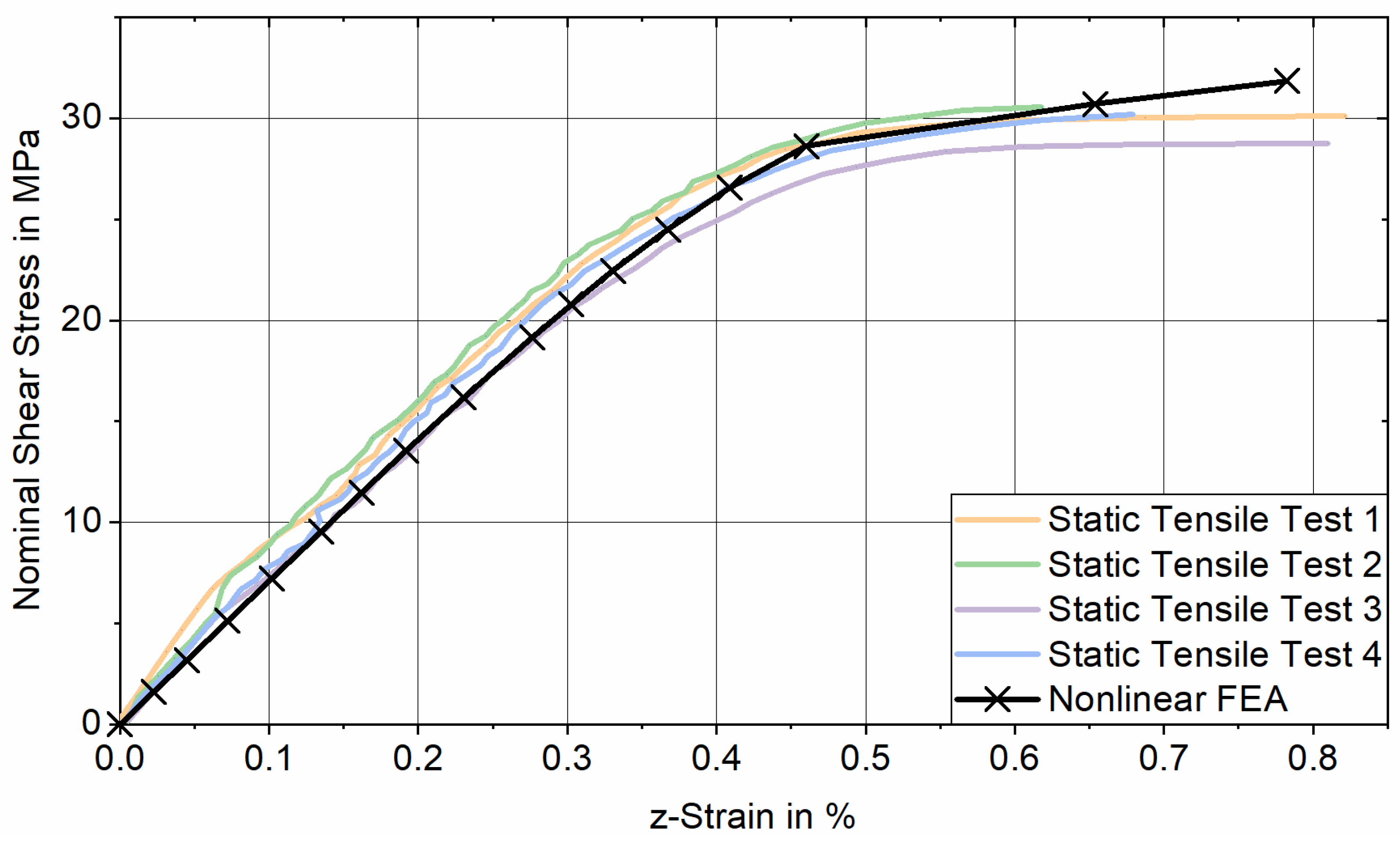
The static tensile tests were carried out using a servo-hydraulic tensile testing machine (Schenck, Trebel). The bonded samples were fixed over a clamping range of using wedge grips. To steadily increase the load on the joint, the testing machine was operated displacement controlled with a constant test speed of [31]. The test results are documented in the form of nominal shear stress versus machine stroke diagrams, from which the maximum measured nominal adhesive shear stress (static bond strength) is determined by relating the maximum force measured to the sleeve´s adhesive surface area . A video extensometer (LIMESS, RTSS) was used to measure the -strain between two high-contrast sticky markers applied to the lateral surfaces of the CFRC tube and the AlSi10Mg sleeves (see Figure 2, top). To validate the FE model, the corresponding -strain was determined by means of nonlinear FE analysis by evaluating the difference in -displacement between elemental nodes positioned at the same locations as the contrast lines of the sticky markers. Up to a nominal shear stress of , the stress-strain response obtained from tensile testing aligns well with the results of the nonlinear FE analysis for joints featuring cylindrical reference sleeves, supporting the validity of the FE model (see Appendix A).
The fatigue strength of the joints was determined through pulsating tensile fatigue tests using an SincoTec Power Swing electromechanical resonance testing machine, where eight bonded tensile samples with redesigned test sleeves were subjected to cyclic tensile loading with sinusoidal progression at nominal shear stress amplitudes of or , while eight bonded tensile samples with reference test sleeves were subjected to nominal shear stress amplitudes of and . All tests were conducted with identical stress ratios of and test (resonance) frequencies ranging from to . Four tensile samples were subjected to each stress amplitude and the number of load cycles endured was counted until the maximum endurable stress of the test sleeve’s adhesive bond dropped below of the respective maximum stress . The load amplitudes were determined during preliminary tests to ensure that the number of endurable load cycles ranges from to . Accordingly, the results can be presented in a Wöhler (S-N) diagram, where a finite-life fatigue curve for each sleeve is evaluated at a failure probability using the horizontal method [32].
3. Results
3.1. Numerical Results
Figure 3 depicts the topology (DS and NDS) of the optimum sleeve (as a direct result of the FE-based TOP process), the redesigned sleeve (based on the optimum sleeve, abstracted in favor of PBF-LB/M manufacturability) and the cylindrical reference sleeve in a sectional view by means of a contour plot.
With a total mass of , the segment of the optimum sleeve achieves a mass reduction of approximately compared to the initial weight of the DS, while exhibiting a maximum von Mises stress of (. Due to the abstraction of the optimum sleeve´s contour in favor of PBF-LB/M manufacturability, the redesigned sleeve exhibits an average deviation from the optimum element density of . This results in a minor increase in total mass of and a slight decrease in maximum von Mises stress to MPa. The impact of this optimization degradation on the adhesive stress state is evaluated by comparing the first principal stress distribution at adhesive mid-thickness for nonlinear FE analysis of joints featuring the optimum sleeve and the redesigned sleeve for loading with a nominal adhesive shear stress of . To put these results into perspective, they are compared to the first principal stress distribution determined for nonlinear FE analysis of joints featuring a non-optimized reference sleeve (Figure 4).
With a maximum first principal stress of , the adhesive bond of the optimum sleeve results in a maximum adhesive stress increase of in relation to the reference value of . Compared to the cylindrical reference sleeve, having a maximum adhesive stress increase of () this is a significant improvement. Looking at the course of the first principal stress for the redesigned sleeve, a maximum adhesive stress increase of () applies. Although the maximum stress increase is reduced by compared to the reference sleeve, the optimization degradation in favor of PBF-LB/M manufacturability results in a higher maximum stress increase compared to the optimum sleeve. Consequently, the optimum sleeve effectively transfers the load through adhesive shear stress, whereas the proportion of load transferred via adhesive peel stress progressively increases from the redesigned sleeve to the reference sleeve. Due to the adhesive´s non-linear stress-strain-behavior, it is to be expected that FE analysis at different nominal loads will result in varying adhesive stress increases. Figure 5 depicts the course of the first principal stress at adhesive mid-thickness along the overlap when the joints are subjected to a nominal adhesive shear stress of .
By exhibiting maximum first principle stresses of (Optimum Sleeve); (Redesigned Sleeve) and (Reference Sleeve), the corresponding maximum adhesive stress increases rise from at to at (Optimum Sleeve); at to at (Redesigned Sleeve) and at to at (Reference Sleeve). The maximum first principal strain reaches for the joint featuring the reference sleeve. Since applies, linear FE analysis is permissible [33]. Due to less adhesive plasticization at lower loads, local stress increases can only be reduced to a limited extent by yielding. This effect is most pronounced in the adhesive bond of the reference sleeve, where the maximum stress increase rises by when comparing higher to lower loads. The adhesive bond of the optimum sleeve shows a slightly lower increase of between higher and lower loading, while the redesigned sleeve exhibits the smallest increase in maximum stress at . This smaller increase induced by the redesigned sleeve can be attributed to its topology already deviating from the optimum due to abstraction in favor of PBF-LB/M manufacturability. In contrast, the optimum sleeve topology is optimized towards loading with and thus no longer aligns effectively with the stiffness requirements at divergent loading (i.e. . As a result, the maximum adhesive stress increase induced by the redesigned sleeve exceeds that of the optimum sleeve for reduced loading at by only ( at ), while falling below the maximum stress increase induced by the reference sleeve ( at ). In relation to actual bond strength, this indicates that the service life of the redesigned sleeve should exceed that of the reference sleeve, with the difference becoming more pronounced at lower nominal shear stress amplitudes. In contrast, the gain in static tensile strength is expected to remain limited, as local adhesive yielding continues to alleviate stress increases.
3.2. Experimental Results
3.2.1. Static Strength
Figure 6 depicts the maximum nominal adhesive shear stress for static tensile testing of eight tensile test samples featuring four PBF-LB/M manufacturable redesigned sleeves and four conventionally manufacturable (cylindrical) reference sleeves single-lap bonded to unidirectional CFRC tubes.
Assuming a gaussian normal distribution, the mean values () of the maximum nominal adhesive shear stress and standard deviations (SDs) of the adhesive bonds featuring redesigned and reference sleeves can be evaluated to and . To determine if the mean values vary significantly (significance level of , i.e. ), an independent one-tailed homoscedastic student´s t-test was executed. The -value comparing the mean values calculates to . Since , it can be concluded that the difference in static bond strength between the redesigned and reference sleeve is insignificant.
3.2.1. Fatigue Strength
Figure 7 depicts the results of pulsating () tensile fatigue tests conducted at nominal shear stress amplitudes of and (redesigned sleeve), and and (reference sleeve), using four bonded tensile test samples per load amplitude.
The evaluation of the test results for the tubular joints featuring non-optimized reference sleeves, based on a logarithmic normal distribution with a failure probability of , yields a slope exponent of the corresponding finite-life fatigue curve of . The corresponding service life is at a load amplitude of and at a load amplitude of . An identical evaluation of the tubular joints featuring redesigned sleeves results in a slope exponent of the corresponding finite-life fatigue curve of , with a service life of at a load amplitude of and at a load amplitude of . By extrapolating the finite-life fatigue curves towards higher load amplitudes, an intersection point is identified at and . At this load amplitude, the tubular joints featuring redesigned and reference sleeves exhibit similar service lives. As the load amplitude decreases, the service life of the redesigned sleeve increases more rapidly than that of the reference sleeve due to the higher slope exponent. Consequently, at a nominal shear stress amplitude of , the redesigned sleeve achieves a service life that exceeds that of the reference sleeve by . By utilizing the Basquin equation, the service lifes of reference sleeves corresponding to failure probabilities of (), () and () at a load amplitude of can be determined. Based on these values, the standard deviations of the service lives of joints featuring both reference and redesigned sleeves can be calculated at the same load amplitude. By comparing the t-value Since obtained from Welch’s t-test with the critical -value for a significance level, determined using the Welch-Satterthwaite equation, it can be concluded that there is a significant difference in service life between redesigned and reference sleeve.
4. Discussion
The results of the FE stress analysis of the optimum and redesigned sleeve indicate that, due to the abstraction of the optimum sleeve’s contours in favor of PBF-LB/M manufacturability, the resulting redesigned sleeve demonstrates reduced performance in achieving a homogeneous adhesive shear stress distribution compared to the optimum sleeve. As the advantages of the optimum sleeve topology are associated with the nominal adhesive shear stress considered during the optimization process, the difference in performance between optimum and redesigned sleeve topologies decreases for load conditions deviating from the one considered in the optimization process. Upon comparing the results obtained for FE stress analysis of the non-optimized reference sleeve with the redesigned sleeve, it was found that the maximum adhesive stress increase induced by the reference sleeve exceeds the maximum adhesive stress increase of the redesigned sleeve by for loading with and by for loading with . This shows that the benefits of the redesigned sleeve in terms of achieving a homogenous adhesive stress distribution become more pronounced at lower loads, as for reduced adhesive ductility, the ability to relieve stress increases through adhesive yielding is limited. The significant influence of the adhesive plasticity on performance of optimized adherend geometry is also evident when comparing the peak peel stress reduction between optimum and reference sleeve topologies evaluated in this study to the peak peel stress reduction obtained for TOP of a rectangular SLJ using an energy-based failure criterion in [19]. As in [19] adhesive plasticity was neglected in the corresponding FE analysis, the total peak peel stress reduction between optimum and reference geometry exceeds that obtained in this study by almost a factor of two.
In the course of static tensile tests using bonded tensile samples featuring redesigned and reference sleeves, there was no difference in bond strength demonstrable. The discrepancy between the numerical and experimental results can be attributed to underestimation of the adhesive’s ductility in the FE model. Once the adhesive’s ultimate strength of is exceeded, the final slope of the multilinear stress-strain curve (as presented in Table 1) is extrapolated and, consequently, accounts for all stress-strain conditions beyond the ultimate strength. Assuming perfect plasticity of the adhesive after surpassing its ultimate strength would significantly reduce numerical stress increases for all sleeve topologies. A more accurate representation of the joint´s structural failure behavior could also be achieved by incorporating fracture mechanics into the FE model using CZM. As shown in [12], by implementing cohesive zone elements at the interfaces between adhesive and adherents their degradation based on a traction-separation law could be captured, resulting in more accurate stress-strain prediction for ductile adhesives at higher loads [34].
Since the adhesive exhibits minimal plasticization during pulsating ( fatigue tests at loading with nominal shear stress amplitudes between and , a correlation between the numerical adhesive stress increase and the corresponding service live was captured. The finite-life fatigue curves of tubular joints with redesigned and reference sleeves show that, as the load decreases, adhesive plasticization diminishes, resulting in a fourfold increase in service life of the redesigned sleeve compared to the reference sleeve at a shared load amplitude of .
5. Conclusions
The findings emphasize that the effectiveness of adherend TOP with respect to increased bond strength strongly depends on the structural-mechanical behavior of the adhesive and the applied load regime. Incorporating adhesive plasticity in FE-based analysis and optimization is crucial when using ductile adhesives, as the adhesive stress distribution is significantly affected by the material's ability to locally yield and redistribute stresses. Consequently, the effectiveness of an optimized adherend geometry in reducing adhesive stress concentration depends on the applied load and diminishes for loading conditions deviating from those considered in the optimization process.
Furthermore, the performance of the optimized adherend geometry is reduced for abstracting the topology in favor of manufacturability. In this regard, additive manufacturing presents a key advantage, as it enables designers to minimize optimization degradation through the realization of complex geometries with variable stiffness and internal cavities. Future studies could focus on minimizing optimization degradation by incorporating lattice structures, particularly at critical regions such as the overlap start and end, where adhesive stress increases are most pronounced.
The comparison between experimental and numerical results highlights the necessity of accurately modeling adhesive plasticity and failure behavior within the FE framework, particularly when aiming to improve static bond strength. Future studies should focus on refining the representation of adhesive failure mechanisms by integrating cohesive zone models into the topology optimization (TOP) process. This would enable more reliable predictions of adhesive stresses while simultaneously identifying advanced, high-performant designs.
Author Contributions
Conceptualization, R.S. and M.A.; Methodology, M.A.; Formal analysis, M.A.; Investigation, M.A.; Resources, R.S. and M.A.; Writing—original draft preparation, M.A.; writing—review and editing, M.A.; Visualization, M.A.; Supervision, R.S.; Project administration, R.S.; Funding acquisition, R.S. All authors have read and agreed to the published version of the manuscript.
Funding
This research and the APC was funded by “dtec.bw – Digitalization and Technology Research Center of the Bundeswehr” (project: FLAB-3Dprint) which we gratefully acknowledge. dtec.bw is funded by the European Union – NextGenerationEU.
Institutional Review Board Statement
Not applicable.
Informed Consent Statement
Not applicable.
Data Availability Statement
The original contributions presented in this study are included in the article. Further inquiries can be directed to the corresponding author.
Acknowledgments
The authors would like to thank Genny A. Pang for her contribution to the manuscript.
Conflicts of Interest
The authors declare no conflict of interest.
Abbreviations
The following abbreviations are used in this manuscript:
| AM | Additive Manufacturing |
| PBF-LB/M | Laser-based powder bed fusion of metals |
| FE | Finite Element |
| GA | Generic Algorithm |
| TOP | Topology Optimization |
| SLJ | Single-lap joint |
| CZM | Cohesive Zone Model |
| SIMP | Solid isotropic material with penalization |
| SLTJ | Single-lap tubular joint |
| 2C | Two-component |
| CFRC | Carbon fiber reinforced composite |
| DS | Design Space |
| NDS | Non-design Space |
| RBE | Rigid Body Element |
| SD | Standard Deviation |
| CAD | Computer-aided Design |
| ED | Element Density |
| HT | High Tenacity |
Appendix A
Appendix A.1
Figure A1.
Stress-strain response obtained for static tensile testing of four tensile samples involving reference sleeves and nonlinear FEA of the corresponding joint.
Figure A1.
Stress-strain response obtained for static tensile testing of four tensile samples involving reference sleeves and nonlinear FEA of the corresponding joint.
References
- Pei, E.; Bernard, A.; Gu, D.; Klahn, C.; Monzón, M.; Petersen, M.; Sun, T. Springer Handbook of Additive Manufacturing, 1st ed.; Springer: Cham, Switzerland, 2023. [Google Scholar]
- Yang, L.; Hsu, K.; Baughman, B.; Godfrey, D.; Medina, F.; Menon, M.; Wiener, S. Additive Manufacturing of Metals: The Technology, Materials, Design and Production; Springer International Publishing: Cham, Switzerland, 2017. [Google Scholar]
- Reichwein, J.; Kirchner, E. Part orientation and separation to reduce process costs in additive manufacturing. Proc. Des. Soc. 2021, 1, 2399–2408. [Google Scholar] [CrossRef]
- Reichwein, J.; Geis, J.; Rudolph, K.; Kirchner, E. Design guidelines for the separation of components to combine the potentials of additive and conventional manufacturing processes. Procedia CIRP 2022, 109, 592–597. [Google Scholar] [CrossRef]
- Ascher, M.; Späth, R. Additively manufactured 3D micro scarf adhesive joints. Proc. Des. Soc. 2024, 4, 1717–1726. [Google Scholar] [CrossRef]
- How we build your bike. Available online: https://www.athertonbikes.com/technology/additive-manufacturing.html (accessed on 19 March 2025).
- Ascher, M.; Späth, R. Joining Technology of Additively Manufactured Components: Design Measures for Optimizing the Strength of Adhesively Bonded Joints. In Innovative Product Development by Additive Manufacturing 2021, 1st ed.; Lachmayer, R., Bode, B., Kaierle, S., Eds.; Springer Berlin Heidelberg: Berlin, Heidelberg, Germany; Volume 1, pp 63–81.
- Cavalcanti, D.K.K.; Banea, M.D.; Queiroz, H.F.M. Mechanical Characterization of Bonded Joints Made of Additive Manufactured Adherends. Ann. Dunărea Jos Univ. Galati Fascicle XII Weld. Equip. Technol. 2019, 30, 27–33. [Google Scholar] [CrossRef]
- Cavalcanti, D.K.K.; Medina, M.; Queiroz, H.F.M.; Neto, J.S.S.; Chaves, F.J.P.; Banea, M.D. Recent Advances in Adhesive Bonding of 3D-Printed Parts and Methods to Increase their Mechanical Performance. Ann. Dunărea Jos Univ. Galati Fascicle XII Weld. Equip. Technol. 2023, 34, 17–24. [Google Scholar] [CrossRef]
- Frascio, M.; Marques, E.A.d.S.; Carbas, R.J.C.; da Silva, L.F.M.; Monti, M.; Avalle, M. Review of Tailoring Methods for Joints with Additively Manufactured Adherends and Adhesives. Mater 2020, 18, 39–49. [Google Scholar] [CrossRef] [PubMed]
- Campilho, R.D.S.G. Advances in Adhesive Bonding Techniques for 3D-Printed Components. Clareus Sci. Sci. Eng. 2025, 2.1, 01–02. [Google Scholar] [CrossRef]
- Arhore, E.G.; Yasaee, M.; Dayyani, I. Comparison of GA and topology optimization of adherend for adhesively bonded metal composite joints. Int. J. Solids. Struct. 2021, SAS 111078, 226–227. [Google Scholar] [CrossRef]
- Silva, L.F.M.d.; Öchsner, A.; Adams, R.D. Handbook of adhesion technology, 2nd ed.; Springer: Cham, Switzerland, 2018. [Google Scholar]
- Banea, M.D.; Da Silva, L.F.M. Adhesively bonded joints in composite materials: An overview. Proc. Inst. Mech. Eng. 2009, 223, 1–18. [Google Scholar] [CrossRef]
- Krittanai, C.; Honghirun, T.; Preechasuth, B.; Nusom, Y.; Uthaisangsuk, V. Mechanical and failure behaviors of adhesively bonded dissimilar materials joints incorporating bio-inspired morphological irregularities. Int. J. Adhes. Adhes. 2025, 136, 103865. [Google Scholar] [CrossRef]
- Gonçalves, D.J.S.; Campilho, R.D.S.G.; Da Silva, L.F.M.; Fernandes, J.L.M. The Use of the Boundary Element Method in the Analysis of Single Lap Joints. J. Adhes. 2014, 90, 50–64. [Google Scholar] [CrossRef]
- Canyurt, O.E.; Zhang, J. Pre-stressed adhesive strap joints for thick composite sandwich structures. Int. J. Mech. Sci. 2006, 48, 389–399. [Google Scholar] [CrossRef]
- Kaufmann, M.; Vallée, T. Topology optimization of adhesively bonded double lap joints. Int. J. Adhes. Adhes. 2022, 118, 103238. [Google Scholar] [CrossRef]
- Ejaz, H.; Mubashar, A.; Ashcroft, I.A.; Uddin, E.; Khan, M. Topology optimisation of adhesive joints using non-parametric methods. Int. J. Adhes. Adhes. 2018, 81, 1–10. [Google Scholar] [CrossRef]
- da Silva, L.F.M. Modeling of Adhesively Bonded Joints, 1st ed.; Springer: Berlin, Heidelberg, Germany, 2008. [Google Scholar]
- da Silva, L.F.M.; Campilho, R.D.S.G. Advances in Numerical Modelling of Adhesive Joints. In SpringerBriefs in Applied Sciences and Technology; Springer Berlin Heidelberg: Berlin, Heidelberg, Germany, 2012; pp. 1–93. [Google Scholar]
- Papadopoulos, I.P.A. Numerical analysis of the SIMP model for the topology optimization problem of minimizing compliance in linear elasticity. Numer. Math. 2025, 157, 213–248. [Google Scholar] [CrossRef]
- Sert, E.; Schuch, E.; Öchsner, A.; Hitzler, L.; Werner, E.; Merkel, M. Tensile strength performance with determination of the Poisson‘s ratio of additively manufactured AlSi10Mg samples. Mater. Werkst. 2019, 50, 539–545. [Google Scholar] [CrossRef]
- Schürmann, H. Konstruieren mit Faser-Kunststoff-Verbunden, 2nd ed.; Springer: Berlin, Heidelberg, Germany 2007. [Google Scholar]
- Ascher, M.; Späth, R.; Johlitz, M. Elastoplastic Characterization of a Two-Component Epoxy-Based Structural Adhesive. In Lecture Notes on Advanced Structured Materials 2; Altenbach, H., Hitzler, L., Johlitz, M., Merkel, M., Öchsner, A., Eds.; Springer International Publishing: Cham, Switzerland, 2024; pp. 291–306. [Google Scholar]
- DIN EN ISO 527-2:2012-06; Plastics - Determination of tensile properties - Part 2: Test conditions for moulding and extrusion plastics. Deutsches Institut für Normung e.V.: Berlin, Germany, 2012.
- Diegel, O.; Nordin, A.; Motte, D. A Practical Guide to Design for Additive Manufacturing; Springer Singapore: Singapore, 2019. [Google Scholar]
- DIN EN 1706:2020-06; Aluminium and aluminium alloys - Castings - Chemical composition and mechanical properties. Deutsches Institut für Normung e.V.: Berlin, Germany, 2020.
- Ascher, M.; Brenner, S.; Pang, G.A.; Späth, R. Joining Technology of Additively Manufactured Components: Effects on the Bonding Strength for the Adhesive Application through Inner Channels. Prog. Addit. Manuf. 2023, 8, 711–718. [Google Scholar] [CrossRef]
- Ascher, M.; Pang, G.A.; Späth, R. Method for the design of additively manufactured inner channels intended for adhesive application. Procedia CIRP 2023, 119, 752–757. [Google Scholar] [CrossRef]
- DIN EN 1465:2009-07; Adhesives - Determination of tensile lap-shear strength of bonded assemblies. Deutsches Institut für Normung e.V.: Berlin, Germany, 2009.
- DIN 50100:2022-12; Load controlled fatigue testing - Execution and evaluation of cyclic tests at constant load amplitudes on metallic specimens and components. Deutsches Institut für Normung e.V.: Berlin, Germany, 2022.
- Introduction to Nonlinear Finite Element Analysis Using Altair OptiStruct. Available online: https://altairuniversity.com/free-ebook-introduction-to-nonlinear-finite-element-analysis-using-optistruct/ (accessed on 19 March 2025).
- Ramalho, L.; Campilho, R.; Belinha, J.; Da Silva, L. Static strength prediction of adhesive joints: A review. Int. J. Adhes. Adhes. 2020, 96, 102451. [Google Scholar] [CrossRef]
Figure 1.
Finite element model (components; analysis coordinate system and boundary conditions) for SIMP TOP with respect to homogenous adhesive shear stress.
Figure 1.
Finite element model (components; analysis coordinate system and boundary conditions) for SIMP TOP with respect to homogenous adhesive shear stress.
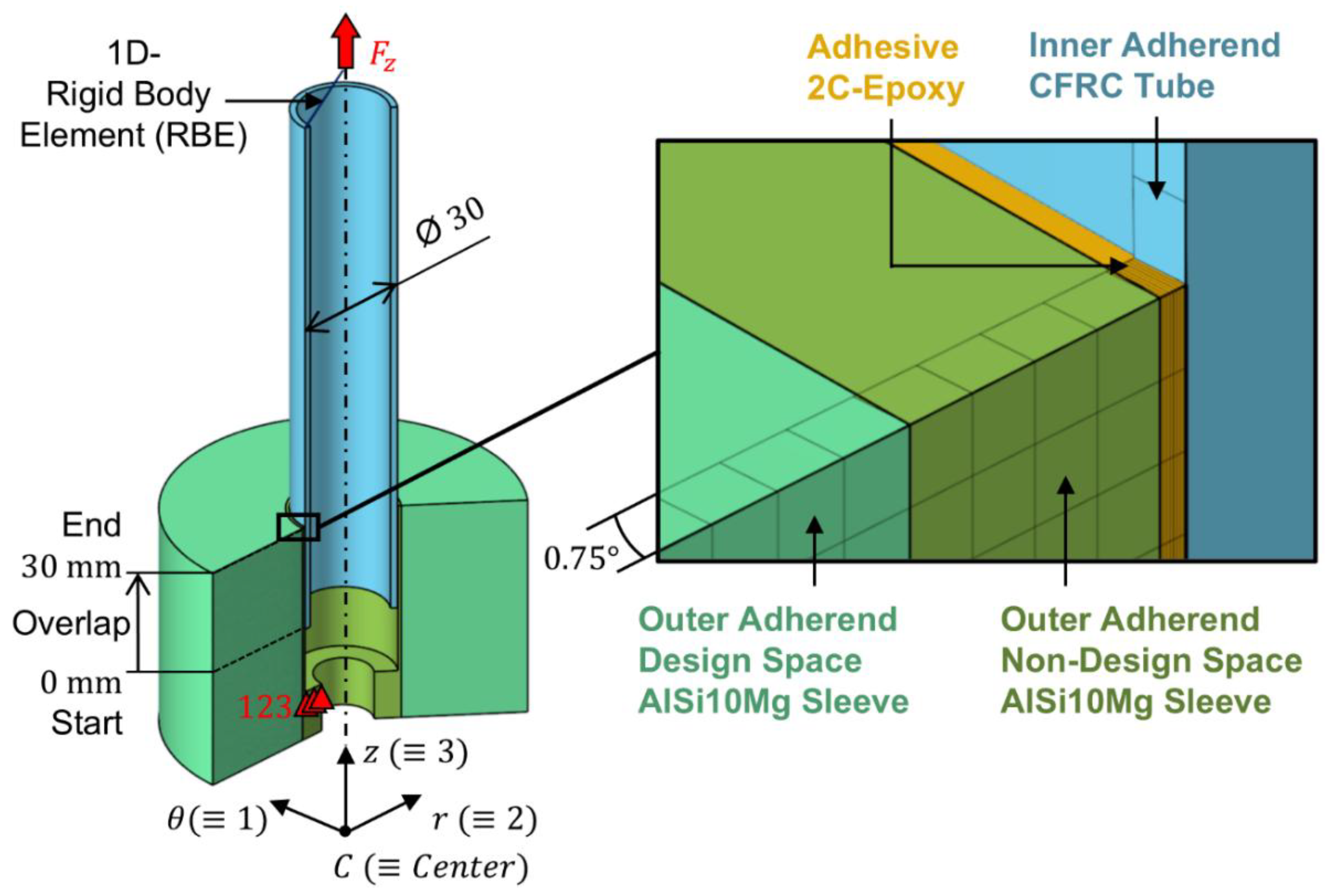
Figure 2.
Schematic of a test sleeve being part of a bonded sample for conducting tensile tests (bottom) and photograph of an entire bonded sample with auxiliary sleeve to clamp the CFRC tube in the test machine (top).
Figure 2.
Schematic of a test sleeve being part of a bonded sample for conducting tensile tests (bottom) and photograph of an entire bonded sample with auxiliary sleeve to clamp the CFRC tube in the test machine (top).
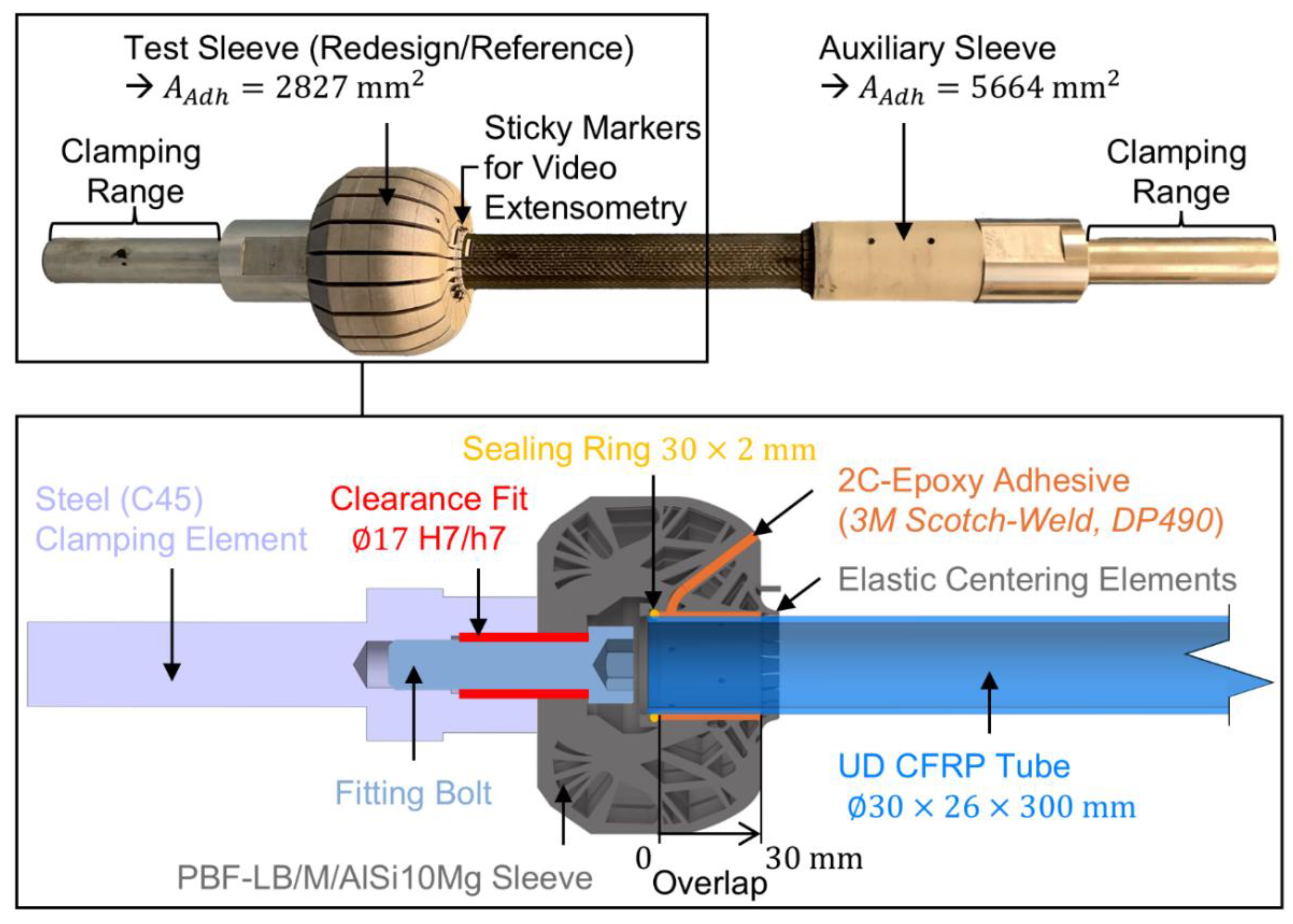
Figure 3.
Contour plot of element densities applying to optimum sleeve, redesigned sleeve and cylindrical reference sleeve ( solid and void).
Figure 3.
Contour plot of element densities applying to optimum sleeve, redesigned sleeve and cylindrical reference sleeve ( solid and void).
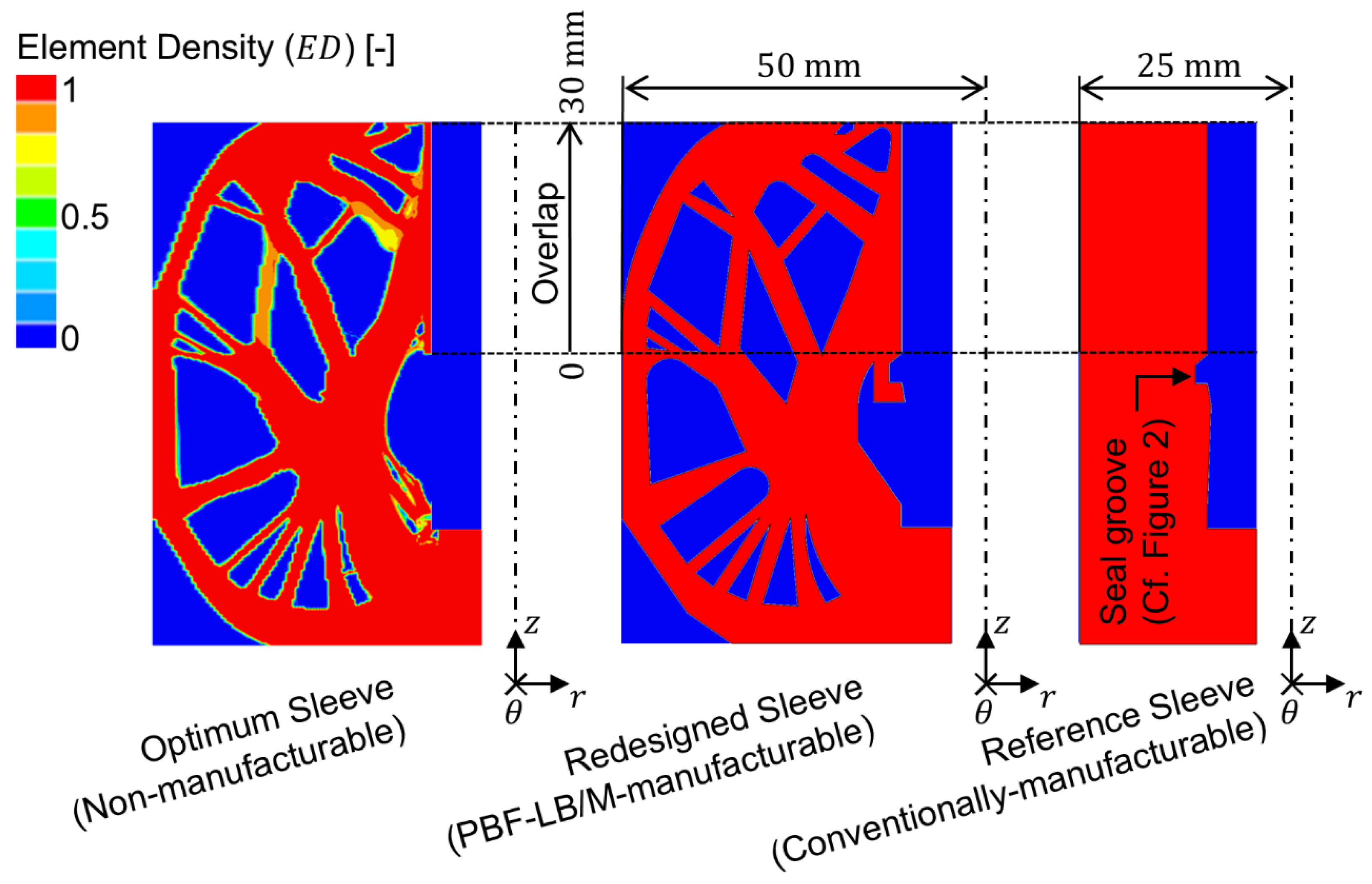
Figure 4.
First principal stress at adhesive mid-thickness as a function of the overlap for nonlinear FE analysis of axially loaded tubular joints between a CFRC tube and sleeves with different topologies (according to Figure 3) exposed to a nominal adhesive shear stress of
Figure 4.
First principal stress at adhesive mid-thickness as a function of the overlap for nonlinear FE analysis of axially loaded tubular joints between a CFRC tube and sleeves with different topologies (according to Figure 3) exposed to a nominal adhesive shear stress of
Figure 5.
First principal stress at adhesive mid-thickness as a function of the overlap for linear FE analysis of axially loaded tubular joints between a CFRC tube and sleeves with different topologies (according to Figure 3) exposed to a nominal adhesive shear stress of
Figure 5.
First principal stress at adhesive mid-thickness as a function of the overlap for linear FE analysis of axially loaded tubular joints between a CFRC tube and sleeves with different topologies (according to Figure 3) exposed to a nominal adhesive shear stress of
Figure 6.
Maximum nominal shear stress for static tensile testing of eight SLTJ between CFRC tubes and AlSi10Mg sleeves with different topologies (according to Figure 3).
Figure 6.
Maximum nominal shear stress for static tensile testing of eight SLTJ between CFRC tubes and AlSi10Mg sleeves with different topologies (according to Figure 3).
Figure 7.
Results for pulsating () tensile testing of tubular joints between CFRC tubes and AlSi10Mg sleeves with different topologies (according to Figure 3) and finite-life fatigue curves for a failure probability of 50%.
Figure 7.
Results for pulsating () tensile testing of tubular joints between CFRC tubes and AlSi10Mg sleeves with different topologies (according to Figure 3) and finite-life fatigue curves for a failure probability of 50%.

Table 1.
Material parameters of the adherends (AlSi10Mg Sleeve according to [23] and CFRC Tube according to [24]) and the 2C-Epoxy adhesive according to [25].
| Parameter | Elastic Modulus in GPa |
Shear Modulus in GPa |
Poisson's Ratio in - |
Density in g/cm3 |
|||
|---|---|---|---|---|---|---|---|
| AlSi10Mg Sleeve (linear isotropic) |
- | ||||||
| CFRC Tube (linear orthotropic) |
|
|
|
- | |||
| 2C-Epoxy Adhesive (multilinear isotropic) |
- | - | |||||
| Support Points of the Adhesive´s multilinear Stress-Strain-Curve | |||||||
| Tech. Strain in % | |||||||
| Tech. Stress in MPa | |||||||
Table 2.
Manufacturing parameters used to fabricate AlSi10Mg sleeves using a DMG MORI LASERTEC 30 SLM PBF-LB/M additive manufacturing machine.
Table 2.
Manufacturing parameters used to fabricate AlSi10Mg sleeves using a DMG MORI LASERTEC 30 SLM PBF-LB/M additive manufacturing machine.
| Parameter | Hatch/Contour |
|---|---|
| Scanning Speed [mm/s] | |
| Laser Power [W] | |
| Focus Diameter [µm] | |
| Layer Thickness [µm] | |
| Hatch/Contour Offset [µm] | |
| Rotation Angle of Scan Pattern [°] | |
| Inert Gas Flow Rate [l/min] | |
| Oxygen Target Value [%] | |
| Base Plate Heating Temperature [°C] | |
| Focus Diameter [µm] |
Disclaimer/Publisher’s Note: The statements, opinions and data contained in all publications are solely those of the individual author(s) and contributor(s) and not of MDPI and/or the editor(s). MDPI and/or the editor(s) disclaim responsibility for any injury to people or property resulting from any ideas, methods, instructions or products referred to in the content. |
© 2025 by the authors. Licensee MDPI, Basel, Switzerland. This article is an open access article distributed under the terms and conditions of the Creative Commons Attribution (CC BY) license (http://creativecommons.org/licenses/by/4.0/).
Copyright: This open access article is published under a Creative Commons CC BY 4.0 license, which permit the free download, distribution, and reuse, provided that the author and preprint are cited in any reuse.


