
Submitted:
29 March 2025
Posted:
31 March 2025
You are already at the latest version
Abstract
The work focuses on developing and exploring the concept of topological responsiveness which is a new approach in architecture. Based on geometric responsiveness and mechatronic work, the principles and form of a new responsive architecture model and behavior are conceptualized. A model of modular responsive structure is proposed for based on formulated guides. Using modeling and analysis, a model was prepared for testing entire structural layouts in Rhino Grasshopper as well as a single module in Autodesk Inventor. The research was conducted using an evolutionary algorithm. First, the usability of the solution was determined for different shapes and sizes of structures, then the effect of scale and aspect ratio was studied. Next, for the best-fit structure, the effectiveness of using the responsive solution was tested and compared with static topological optimization solutions for vertical and horizontal loads according to a uniform load model. As a result of the modeling work, a 1:10 scale physical model of the module was then prepared for further research. The conclusions outlined the tendencies of the system for simplifying further analysis and reducing the time of searching for effective topologies. In addition, the principles and scope of applicability of the solution are defined.
Keywords:
responsive architecture
; topological responsiveness
; evolutionary algorithm
; adaptive structures
; architectronics
; mechatronics in architecture
1. Introduction
1.1. Actual Research
With the advancement of technology and the growing emphasis on sustainability and material efficiency, architecture and its related fields are increasingly leveraging solutions that enhance resource efficiency. One emerging approach is the development of responsive architecture, which allows load-bearing structures to adapt to changing environmental conditions. From William Zuk’s Kinetic Architecture [1] to modern high-tech solutions presented in [2], structural responsiveness has evolved into various forms, including changes in element lengths, both in discrete constructions and, increasingly, in continuous shell and plate structures, as discussed in [3] and methodologically examined in [4]. These adaptations influence the geometry or stress distribution within a structure. Current research focuses primarily on geometric responsiveness, achieved through mechanical or pneumatic actuators, nitinol elements, and tensioning systems. Studies in this field emphasize the optimal selection of actuators, as presented in [5], where minimizing their number is crucial for energy efficiency, optimizing movement trajectories, and selecting geometries or behavioral models that ensure maximum energy savings over the structure’s lifespan, as demonstrated in [6]. A key challenge in this analysis lies in designing sufficiently complex systems for environmental sensing, structural diagnostics, and compensating for inaccuracies. These studies consistently seek a balance between data amount and relevance, as defined in [7] that prevents system overload. Measurement systems, an integral part of every responsive structure, require the simultaneous collaboration of multiple scientific disciplines, making each project inherently interdisciplinary. However, research on responsive architecture remains largely limited to geometric adaptability. This limitation is compounded by the lack of suitable actuators for large-scale implementations, as noted in studies on efficient responsive geometries [8], and the need for customized measurement apparatus, which is further explored in terms of application and maintenance challenges in [2]. Additionally, geometric variability restricts the effective use of space within and beneath the structure, as illustrated in Figure 1.
The authors propose a new research direction based on topological variability, a concept not yet explored sufficiently in architectural studies.
Topological responsiveness presents a distinct approach compared to the increasingly studied geometric responsiveness. Unlike shape variability, which focuses mostly on external form with elements elongation, topological responsiveness operates within the connections between structural elements.
In the case of truss structures discussed in this study, its fundamental mechanism involves rotational movement within multiple spatial dimensions, marking a new research direction in a field dominated by actuators altering elements length. Previous implementations of topologically responsive structures have been limited to theoretical considerations of motion or rigid, single-stage topological optimization, as explored in [9]. In its simplest form, a broader application of topological responsiveness shifts variability from bars to nodes in discretized systems. Here, bar lengths remain constant, while nodes assume the role of determining connectivity and disconnection between elements. This introduces new engineering challenges and design constraints that need to be addressed in both research and technological applications. Currently, no architectural studies propose structures capable of topological variability during a building’s operational lifespan. This capability is mainly associated with mechatronics and mechanics. The most closely related field utilizing similar principles is Variable Topology Truss (VTT), as described in [10]. VTT, an area within robotics and mechatronics, focuses on the design, implementation, and control of robots capable of reconfiguring their topology through fully automated connection and disconnection systems. These systems coordinate robot movement while ensuring stability and reliability during topological as well as geometrical changes, a core principle of the model discussed in [11]. Geometric changes in such robots enable spatial movement by shifting their center of mass, whereas topological changes allow precise motion control. To facilitate variability, a unified node model has been developed that maintains the required connection rigidity at a small scale while also preserving the orientation of its dynamically connecting elements in a non-inertial space. This significantly increases the complexity of the employed joints. The assumption behind this design is that each VTT can move freely in any direction without maintaining any permanent connection to the ground.
However, when adapting mechatronic solutions to architecture, it is possible to establish a nonzero fixed connection to the ground without losing functionality of movement, providing at least one reference point for it. Additionally, by imposing stricter rigidity requirements—anchoring the structure and transforming the mechanism into a self-supporting structure—technological complexity can be reduced by confining movement to specific elements within a static rigid frame. Despite these potential adaptations, scale remains a major challenge. The extremely low load-bearing capacity of VTT robots compared to architectural structures prevents direct application of mechatronic models in human-scale environments. This highlights a significant divergence between VTT systems and architectural topological responsiveness, driven by their fundamentally different movement objectives. Scaling up nodes and robotic actuation generates numerous technical issues, making it difficult to move beyond theoretical considerations of motion.
1.2. Concept of a Topologically Responsive Model
Topological responsiveness, in its theoretically unconstrained form, allows for the unrestricted repositioning of every structural element. The first limitation imposed on this movement comes from the interpretation of its application domain. In architecture, a structure’s fixed connection to the ground necessitates at least one reference point. Implemented as a rigid support, this reference point not only serves as an anchor for the structure but also provides a fixed orientation, simplifying movement mechanics. However, this restriction limits variability to elements that are not directly connected to the supports, which remain static. Another key limitation is ensuring structural rigidity during movement. Each element, when repositioning relative to the others, requires a supporting framework or other form of temporary redundancy. This means that moves cannot occur simultaneously across all elements, leading to sequenced displacement. Additionally, a stable framework of fixed elements is required to enable movement of the remaining components. While the specifics of these constraints are refined during structural modeling, motion planning, and connection design, at the conceptual stage, they define a modular division of the structure. Each module is designed with an identical or analogous geometric form and consists of both movable and fixed components, creating a hybrid structure where rigid and adaptive elements coexist. For further movement simplification, it is reduced to rotation only, which is possible as long as modular units maintain a stable structural framework. By limiting the geometric variability of topologically responsive models, the need for telescopic extensions of structural bars is eliminated. A square-based module meets these requirements, serving as the framework for movement within which transformations occur. Within a single frame, all movement processes takes place. A single internal bar, selected for its appropriate stiffness, moves along a circular trajectory, enabling topological transformation through a nodal pivot point. This concept provides a foundation for an adaptive yet structurally stable system, balancing responsiveness and rigidity, and paving the way for new possibilities in reconfigurable architectural structures.
1.2.1. Preliminary Assumptions for Topological Responsiveness:
- Single-Plane Motion for Simplification
To simplify movement, the motion of the structural bar is restricted to a single plane. Introducing a third dimension of movement would significantly complicate the structure and require even greater precision in motion execution.
- Load-Transferring Connections
The method of connecting elements is designed to allow the transfer of both compressive and tensile stresses. While the specifics of the connections will be discussed later in the study, this fundamental assumption is established at the conceptual stage. This necessitates bilateral connections, which are more prone to structural flexibility and looseness over time.
- Discretized Topological Variability of Bars
The bars will have restricted topological variability, allowing only unilateral disconnection at one end. The other end remains permanently fixed to the structure at the axis of rotation. Additionally, movement will be guided along predefined tracks, improving precision during positional adjustments and facilitating accurate reconnection of elements.
- No Preset Constraints on Computational Speed or Response Time
The preliminary assumptions do not impose limitations on the calculation speed of structural behavior or the maximum response time of the structure.
- Rotational Motion and Angular Constraints
By utilizing a continuously adjustable rotational motion, the central bar can theoretically rotate at any angle between 0 and 180 degrees. However, to achieve an optimal axial stress distribution and avoid bending effects, movement is restricted to four predefined positions spacing in 45 degrees gaps and the angular range is limited to 135 degrees. Despite this low topological variability, the system can significantly influence stress distribution within the structure.
The structural design allows for straightforward modular multiplication using peripheral bars to create larger and more complex configurations. These formations can mimic the geometric framework of post-and-beam constructions. By multiplying modules, the number of possible bars arrangements within the structure increases exponentially. The total number of possible topological configurations is given by the formula:
where n represents the number of modules in the structure. As the number of modules grows, the number of possible configurations quickly surpasses computationally feasible limits, making it impossible to analyze all variations in a reasonable time. This necessitates the search for efficient topological configurations through a method that incorporates a degree of randomness. To address this challenge, an evolutionary algorithm is introduced into the analysis. This algorithm guides the search process, effectively reducing the number of configurations that need to be examined while still identifying optimal structural solutions.
1.3. Topology of the Rotating Bar
As the position of the rotating bar changes, the character of the structure also evolves, necessitating further assumptions at the conceptual stage. In two diagonal positions, a single module is divided into symmetrical isosceles right triangles. This results in geometric stiffening of the module, consequently increasing the overall stiffness of the entire system. In the next two positions of the rotating bar, parallel to the peripheral bars, the property of division into rigid triangular spatial cells is lost, replaced by rectangular spaces that do not have inherent rigidity. This requires all the fixed connections in the structure to transfer bending moments, adjusted to the magnitude of the resulting stresses. The stiffness of these connections should compensate, to some extent, for the off-axis forces applied to the structure. These off-axis forces will arise from the finite precision of orientation and joining of elements at the nodal points. Operating with the stiffness of fixed connections, therefore, modifies the range of efficiency for the orthogonal positioning of the rotating bar. With a stiffer frame, the moving part of the bar becomes less significant, reducing the effectiveness of its movement. Additionally, the stiffer the connections are designed, the larger the margin of off-axis external forces, yet at the same time, material efficiency decreases.
Modules can be oriented both vertically and horizontally adopting the shield or plate work nature respectively. The spectrum of structures that can be constructed is limited to orthogonal systems with modules that enable the creation of recesses and cantilever overhangs. Modeling with a single module size aims to reduce costs and decrease material usage. To achieve greater efficiency, further assumptions can be made—horizontally, all directions of the rotating bar system and stress patterns are equally probable. Vertically, however, primary directions and orientations can be distinguished. Vertical gravitational forces will, in most cases, generate only compressive stresses, so the connection in this configuration can be simplified to one that transmits compressive forces along the axis of the bar. The horizontal arrangement of the rotating bar in vertical modules can only be an effective solution for high structures, placed centrally between the external walls. Diagonal connections, on the other hand, can be differentiated, particularly for tall buildings, where similarly effective stiffness can be provided by a bracing system at 45 or 135 degrees. It is assumed that the braced system of moving bars can always be configured to only transfer tensile forces by changing the direction of the bar in the diagonal configuration. This leads to a greater variety of connection solutions, simplifying the construction and increasing the reliability of each module.
A single module influences the performance of the entire system, which is why cooperation between elements is critical for efficiency. In the first phase of research into topological systems, authors will allow full freedom in the resulting topologies within the structure. Based on previous results, a method for simultaneous movements of individual modules should be proposed.
2. Studies on the Effectiveness of Modules for Different
2.1. Preliminary Assumptions
The models subjected to analysis will be evaluated in terms of efficiency, understood as the change in the deflection arrow. Responsive models aim to increase the range of serviceability limit state; therefore, this criterion has been selected for study. To assess the effectiveness of the topologically responsive model, a skeletal structure of a simple object was modeled using Rhinoceros Grasshopper software. The maximum deflection was defined as 1/300 of the span between supports, in accordance with commonly accepted structural engineering assumptions. For a single module with a side length of 10 meters, this results in a maximum deflection of approximately 3.33 cm. Authors further combine these modules to develop a structure that emulates the skeletal framework of buildings.
Initial research aims to identify the most suitable geometries that exhibit the highest sensitivity to changes in topology of the modules. Exploration of geometries seeks to determine the optimal shape proportions and height to base ratio of structures most appropriate for studying proposed form of topological responsiveness. The findings are expected to define the types of geometries and the nature of structural phenomena that are most effectively influenced by the proposed variability system. The study will consider both the proportions and sizes of structural forms.
Two fundamental computational models of the module have been developed for the study, differentiated by the scale at which the analyses are conducted. For assessing the overall stiffness of the structure, a model was created in Rhino Grasshopper using the Karamba 3D plugin. This simplified model consists of replicated modules with idealized geometry, approximating the behavior of each individual module and providing a rapid evaluation of the overall structural stiffness. In contrast, a detailed model incorporating full geometry, motion mechanisms, and joint mechanics was developed in Autodesk AutoCAD 2024, with physical parameters assigned in Autodesk Inventor 2024.
For the detailed model, simulations of individual module behavior were conducted using the Nastran extension for Inventor. This Geometrical model includes a circular rail, as illustrated in Figure 2, allowing for controlled rotational movement of the rotating bar. Furthermore, by integrating connections between the external frame and rotating bar, the issue of element length variability is mitigated. In every configuration, a constant critical force value is assumed for the rotating bar.
2.2. Development of General Model
Model is based on an idealized structural geometry with a square module, initially designed with dimensions of 10m x 10m. The perimeter elements represent the boundary bars of a single module. Subsequently, the rotating bar was introduced and modeled with four manually programmed rotation cases within a range of 0-135 degrees. These predefined positions are connected to a selection filter, allowing to choose between different rotational states. The four-position slider simulates an instantaneous change in the rotating bar’s position, following the theoretical assumptions established in the previous section.
By multiplying, rotating, and connecting additional modules, four full structural frameworks were created, assuming a skeletal construction system:
- Model A: 3x2x5 modules (“base length” x “base width” x “height”), model B:3x1x5 modules.
- Model C: 1x5x4 modules, model D: 2x5x4 modules.
- All configurations maintain identical functionality regarding the movement of the rotating bar, yet theoretically experience different dominant forces.
- Models A, B are primarily deformed by gravitational forces.
- Models C,D are mainly influenced by horizontal loads.
- For all models, the structural elements were assigned thin-walled circular cross-sections with:
- Outer diameter: 25 cm
- Wall thickness: 2 cm
- Material: Structural steel St355
- Mass of a single module: 10 438 kg
During model multiplying, the overlapping of boundary bars from adjacent modules was prevented. Since each module is duplicated as a whole during assembly, common elements at module junctions could lead to redundant structural components. To address this, the models were programmed to automatically detect and remove duplicated bars, ensuring that all fixed elements share identical physical properties.
The finalized geometry and material parameters were then integrated into Karamba 3D’s nonlinear analysis module, employing an iterative Newton-Raphson method for computation.
The model was assigned:
- Constant gravitational acceleration, applied at the centroid of each bar.
- Additional lateral surface loads, distributed across one side of the structure, simulating commonly applied wind pressures.
To couple the model with an evolutionary algorithm, all four-position sliders controlling the rotation of the rotating bars were connected to Galapagos, the evolutionary solver embedded in Rhinoceros Grasshopper.
- The input variables for the algorithm are the discrete rotational states of the rotating bars.
- The algorithm does not recognize the physical phenomena it controls but generates numerical codes interpreted by the filter controller for each module independently.
- The fitness function is defined by the maximum deflection of the most deformed bar. Deformation is defined as translation between initial geometry and displaced.
Each structural model includes fixed, non-displaceable hinge supports, rendering the system statically indeterminate.
For computational efficiency, certain structural constraints were not explicitly modeled:
- The guiding rail of the rotating bar, which was described conceptually, is not included in the simulation.
- Consequently, the length of the operating bar changes between positions, affecting its critical buckling force.
- To simplify the analysis, a constant critical force value was assigned to the rotating bar manually in all positions.
-
No inaccuracies are modeled, meaning:
- All applied forces are assumed to be perfectly axial.
- All components are connected with exact parallelism at their joints.
These assumptions allow for a faster evaluation of the topological effects on structural responsiveness while maintaining computational feasibility.
2.3. Operation of the Model
The evolutionary algorithm aims to find the most efficient arrangement of operating bars to determine the most effective topology for a given set of external forces. It identifies trends that allow for an increase in user-defined efficiency by analyzing relationships between parameter variations. Initially, the algorithm modifies individual input values and then, by grouping them, makes progressively larger changes in single iterations. Each time it starts a search, it creates a new empty database, which is then populated with information about mutual relationships, effective value ranges, and proportions of result changes to input value modifications. The algorithm operates most efficiently for quantified slider values, as defined in the Grasshopper model.
This model is characterized by a large number of input parameters with a limited range of possible values, making it an effective use case for the algorithm. Each structure, according to the previously described principle, has too many different topological configurations for the system to analyze all of them within a reasonable timeframe for a single load case. The algorithm searches for modification directions that provide efficient changes and minimizes the number of cases examined before achieving a satisfactory result. Attention must be paid to the issue of premature convergence. This topic is discussed further in the study of the efficiency of grouped and dispersed topologies under horizontal and vertical load limits. Throughout the study, the evolutionary algorithm was set with identical parameters, targeting the minimization of deflection values. The maximum stagnation was set at 15 evolutions, with a population size of 50 per iteration and an initial boost of x2. The maintain rate was 5%, and inbreeding was set to over 75%. The study was conducted on a laptop with a dedicated graphics card, featuring an Intel Core i7-10700H 3.7GHz processor and 32GB of DDR3 RAM.
The preliminary study aims to determine the higher efficiency of spatial modules for either tall structures or surface-based structures. The evaluation considers the increase in structural stiffness achieved through topology optimization using the evolutionary algorithm. This is quantified as the ratio of the deflection of a standard bar diagonal arrangement to the deflection of a structure optimized by the algorithm. The results guide the selection of structural forms used in further studies and determine the dominant orientation of elements (vertical or horizontal), influencing subsequent connection design decisions. For each topology analysis, the structural force distribution remains unchanged. Each test lasts 60 seconds, during which the model evaluates an average of 1,400 structural configurations per case. Tests were conducted on models in four geometric cases, as illustrated in Figure 3. For each model, data on deflection before and after topology optimization was collected and compiled in tabular form.

Table 1.
Deflection values for different configurations. Bottom coefficient shows degree of effectiveness for proposed topological responsiveness.
Table 1.
Deflection values for different configurations. Bottom coefficient shows degree of effectiveness for proposed topological responsiveness.
| Deflection arrow [mm] | Load case number | |||
| 1 | 2 | 3 | ||
| A | 95,36 | 477,94 | 463,90 | |
| 88,10 | 416,85 | 405,46 | ||
| 0,92 | 0,87 | 0,87 | ||
| B | 105,07 | 659,81 | 646,04 | |
| 144,39 | 744,93 | 827,30 | ||
| 1,37 | 1,13 | 1,28 | ||
| C | 197,34 | 1752,84 | 2684,74 | |
| 176,31 | 1183,11 | 1615,55 | ||
| 0,89 | 0,67 | 0,60 | ||
| D | 202,78 | 3745,00 | 4001,33 | |
| 182,93 | 1405,84 | 1488,90 | ||
| 0,90 | 0,38 | 0,37 | ||
A- horizontal structure with one floor. B - horizontal structure with two floors (a)). C - vertical structure on base 1x4 (b)). D - vertical structure on base 2x4.
For almost every geometry, a more efficient arrangement of the rotating bars was achieved. The most noticeable influence is the effect of horizontal forces on the deflections of individual structures. In the horizontal structure, the difference in the impact between gravity and horizontal forces was 2 to 5 fold smaller than the impact on the vertical structure. For case “B,” no more efficient shape was obtained in any instance. The reference bars arrangement for this structure assumed the placement of all operating bars as shown in the graphic. The model does not maintain geometric stiffness. Minimal horizontal forces generate large bending moments at the joints, but these are not dominant values; therefore, for every case of the investigated load, it was more effective to arrange all the moving elements parallel to the vertical forces, resulting in the most axial transfer of stresses. For larger values of horizontal loads, significantly more effective results from the evolutionary algorithm are expected. The cost-effectiveness threshold for using the evolutionary algorithm requires separate investigation. For the vertical structure, the improvement is between 80-205%. This indicates a significantly greater efficiency of module use in tall structures, where most of the modules will be positioned vertically. This implies the possibility of modules working similarly to bracing tendons in skeletal structures. Furthermore, as the element slenderness increases, the effectiveness of topological modification of the structure increases. This paths further research toward tall structures.
Next, the scale and height of the responsiveness predestinated structure are studied. For further geometries of tall structures, a series of studies were conducted using the evolutionary algorithm operating with the topology system. For structures with a base of 1x1, 2x2, and 3x3, modules were tested for changes in stiffness during manipulation of the main bars, similarly to the first study. The modification process was performed for seven additional loading cases. In each case, the gravitational force was equal to 9.98 m/s², and in 6 of the studies, wind loading was additionally modeled in the form of a simple triangular surface load increasing in value upward, applied to the outer surface of the structure and then distributed to the nodes as concentrated forces. A reference value of 1.0 corresponds to the average horizontal forces value used for similar real-world structural studies, which is 0.44 kN/m² as denoted in Table 2. For each structure, 1300 configurations were analyzed by the algorithm to minimize the deflection parameter, measured in millimeters. For every model in every load case there were 3 configurations examined according to Figure 4.
The initial geometry for all shapes and loading cases is the bracing of modules in one direction. This serves as the default configuration, acting as a reference for measuring the effectiveness of the responsive model. The coefficients, presented with color codes in the Table 3, represent the ratio of the third value to the second one—this is the result of algorithm modification compared to the simple bracing structure. An additional reference is the arrangement of central bars in a vertical position. This configuration is generally ineffective, but when vertical forces dominate over horizontal ones (i.e., no wind), it becomes the most effective geometric form. For cases where the horizontal force is near zero, the algorithm did not find any more efficient geometry, suggesting that there is a threshold for activating the system based on wind force. This activation threshold is within the range of 0.0–0.1 horizontal force, or below 0.042 kN/m². Below this threshold, all bars should be oriented in the vertical position by default, indicating the need to define the activation boundary of the algorithm.
The most significant improvement in efficiency for 2x2x4 structures with a lateral force of 0.5g highlights the correlation between effective wind force and structural height to base ratio. For structures with high height to base ratio, low lateral loads were effective, whereas for increased force, squat models yielded better results. The most efficient height to base ratio for future tests was assumed to be 1:4, where the first parameter is the number of modules in a square base in both directions, and the second is the height of the structure, also measured in modules. The average scale of the tested models was 2x2 in the base. Although additional deformations were not presented, it was observed that as the height of the model increased, regardless of its narrowness, global twisting of the structure became noticeable, especially under wind force. Separate studies should address the modules’ ability to counteract this phenomenon or define the orientation of new modules to increase torsional rigidity. The maximum rotation occurred for the 2x2x8 module, reaching 5.32 degrees for simple bracing. For the optimized system, this rotation was reduced to 4.18 degrees. However, not every case showed an increase in torsional stiffness due to the EA (evolutionary algorithm) modification. The 3x3 module base structure displayed uneven twisting, and the following rotations (in degrees) were observed for each floor:
The model maintains very good structural stiffness up to the 5th floor. Beyond this point, the tilt angle increases due to the axial limit of the vertical bars. On the 7th floor, the twist reaches its maximum value, as the axial threshold is exceeded. At this stage, stiffness is maintained by vertical modules that connect the external modules to the structural core. These elements experience the greatest length variation under torsion. Their rotation within the module to reduce deformation illustrates the system’s preference for subjecting central bars to tensile rather than compressive forces, which aligns with standard design principles. Figure 5 performs described tendencies and similar overall and individual bars geometry.
2.4. Tendencies of Rotating Bars Arrangements
The arrangements obtained through the evolutionary algorithm exhibit a clearly random pattern. Their topology lacks the structured layouts and patterns characteristic of the most efficient, widely used solutions. This randomness affects the final efficiency of the system. It arises due to the overwhelming number of possible configurations that need to be analyzed to find an optimal arrangement of adjacent modules. Despite significant variations in the arrangement of all structural bars, local patterns and stiffness-enhancing tendencies can be observed. The lower section of the structure (I) has the greatest impact on deformations. The I segment of the elements, measured from the bottom, plays the most crucial role in structural efficiency by minimizing the computational effort required to achieve maximum stiffness. Most elements in the lower and middle sections (I) and (II) adopt a braced arrangement, utilizing a rotational bar as braces. The algorithm favors structural safety by prioritizing tensile work over compression in bars, leading to an orientation of operating bars that enhances the model’s efficiency. For structures with a larger number of base modules, a repetitive pattern emerges at each vertical level, where the arrangement of operating bars remains consistent across the same height. This is the fastest way to improve stiffness when searching for the quickest viable solutions. With longer computation times, more complex configurations that break this repetitiveness can be identified. Manual adjustments of topology at individual levels improved efficiency in only 13.4% of cases. Due to the vast number of possible combinations, only the smallest structures managed to achieve minimal but highly effective arrangements. Additionally, internal modules contribute significantly less to overall structural stiffness compared to external ones as depicted in Figure 6. The least influential elements in this regard are internal horizontal modules, whose modifications had minimal effect on stiffness. External horizontal modules had a slightly greater impact but still indicated that the base stiffness of the modules was sufficient, with no need for additional horizontal reinforcement.
These findings suggest that topological variability should primarily be used as a tool for vertical bracing, particularly in response to wind loads. Measurements were conducted on three structures to assess the impact of element positioning on overall structural stiffness. These measurements were performed by comparing the worst manually found configuration to the evolutionary algorithm-modified version.
According to distinguishment of elements as described on Figure 7, all modules in all structures were divided into groups. Only in the largest model (3x3x12) did all types of elements appear, classified into 12 types according to the classification.
In smaller models, elements from the II and III segment and internal horizontal modules were absent. The elements were grouped based on previous conclusions from topology analyses and structural deformations. The study was conducted on the following structures: 2x2x8, 2x2x12, 3x3x8, and 3x3x12.The influence and relevance calculations play the crucial role in important bars recognition. Topic is extensively examined in responsive architecture with mathematical formulations like in [12]
To calculate the relevance of modules in high structures under examination, significance calculations were performed first. This was done by dividing the difference in structural deflections for a given module between the worst and algorithm-modified topological configurations by the sum of deflections for the entire structure.
The coefficient is a parameter that defines the contribution of a single module in a specific load case to the overall stiffness of the structure under that load. The parameter ranges from 0 to 1. For all modules in all structures, its values were within the range of 0.0003 to 0.0371.
Next, the structure’s relevance is determined based on the contribution of each bar in every load case. This is different from the commonly used calculation of influence of movement in responsive structures which is converted into a one-dimensional matrix of ready-made results like in [13]. A matrix of values is created to represent the participation parameters of each module.
Next, for further calculations, the parameter with the highest value from each group of load cases is selected.
Next, similarly to the impact calculation, the component of the individual inflow is calculated for the total inflow parameter.
Relevance is therefore a parameter that illustrates the degree of influence of a given section of modules and individual modules based on the averaged values of each module’s contribution. The study was conducted semi-automatically. The search for the values of and was performed manually and recorded ian tabular form. The formatted sheet then automatically recalculated the values of individual components. The results, presented as percentages, are shown in the graphic (***).
For the calculation of the reliability of the obtained values, the IQR test coefficient was used. Due to the inability to examine all possible loading cases, a limited sample required the use of a determination coefficient to estimate the maximum and minimum relevance values that individual modules and sections can achieve according to the Figure 8 The upper and lower limits are taken as the boundaries according to the formulas for Q1 and Q3. similar to the article [14] the formula is to present the uncertainty of obtaining specific data by specifying a confidence interval.
The expected boundary values of relevance for each section were calculated. In the (Figure 7) values marked in red represent Q1, while those in green represent Q3. According to the graphic, the Q1 and Q3 values vary depending on the type of element. A noticeable difference exists between the significance of vertical and horizontal elements. Horizontal elements exhibit a significantly smaller range of values while also having a lesser impact on overall stiffness. The variation in influence is lower for higher-positioned modules, but the range of values proportionally increases for them.
2.5. Conclusions from Effective Geometry Studies
The results demonstrate a varying degree of influence of different structural elements on overall stiffness. The dominant type of elements are vertical, while the presence of core elements in the III segment is not critical; it primarily ensures triangulation and bracing of all structural module cells. According to the findings, the external elements of the I segment have the greatest impact on structural stiffness. Additionally, they are the most significant in counteracting torsion, reducing it by 52%. The second most influential type consists of external vertical elements in the II segment. In all structures, horizontal elements become less important. The entire core of structures with a 3×3 base contributes to overall stiffness in the range of 5% to 14%. In structures with a 2×2 base, horizontal modules exhibit a significantly greater contribution, surpassing internal vertical elements in terms of overall stiffness. In 2×2 structures, some configurations formed orthogonal arrangements of central bars with a tendency toward horizontal orientation. This was particularly evident under predominant vertical loading.
For 1×1 structures, the highest level of pattern repetition was observed at individual levels. From levels 1 to 7 in structures with two or three segments, all elements were diagonally arranged. At higher levels, orthogonal configurations proved to be more effective, leading the algorithm to adopt such layouts. In the largest modules at individual levels, horizontal modules exhibited a pattern where movable bars were extended to ensure continuity between modules. Any manually introduced disruptions to this continuity significantly reduced structural stiffness. This indicates that the set of potentially effective topologies can be reduced to those preserving horizontal bar continuity. Further constraints on possible topologies involve the diagonal orientation of external elements in the I segment of each structural type, but only when a certain threshold of lateral wind load is exceeded. When searching for efficient topologies, the algorithm begins testing from the lowest modules (following the order of attachment). Within the first 20% of computation time, it achieved 60% of the final efficiency in most cases.
The variation in the number of modules of a given type within the structure must also be considered. When calculating significance per individual module, the most effective ones were identified as internal horizontal elements, with a significance of 0.75% per module. These were followed by external vertical elements, whose significance in the lower section averaged 0.563% per module. The least significant elements were external horizontal modules, with a significance of 0.23% per module. For structures with larger bases, the significance of external modules increased accordingly but was unevenly distributed along the perimeter. The highest impact on stiffness was observed in braced modules positioned parallel to the direction of the largest applied forces. The force proportion increased with the structure’s base size and lateral loads coefficient ranging from 1.1 to 4.2.
2.6. Analysis of the Potential Gains from Topological Responsiveness in tall Structures
The previous studies were limited to groups of structures with specific properties, such as height to base ratio or the presence of boundary or internal modules. However, these did not provide direct comparisons where the displacements of static models could be contrasted with those of responsive models. To assess the feasibility, comparative studies were conducted for a single model under several load cases. In order to perform the appropriate efficiency measurements, a new structural model with dimensions 2x2x8 modules was designed, which was subsequently subjected to seven different loading cases. The initial objective of the evolutionary algorithm was to develop a geometry for the individual rotational bars that would result in a universal static bar configuration, minimizing the total displacement for all seven load cases. In the subsequent step, for each load case, the most efficient geometry was individually developed, simulating the behavior of a responsive model capable of adjusting in real-time to varying environmental conditions.
All cases included gravitational force and one or two lateral forces representing wind loads. The gravitational force was constant for all elements and was set to g=9.98 [m/s2], while the wind force varied with height, in accordance with commonly accepted models for variable wind loads depending on elevation. Although the structure is not identical to typical building constructions, the selected scale indicates significant similarity between the studied model and high-rise buildings, with respect to external dimensions and the static load-bearing system. Considering the dimensions of the structure’s walls to be 20x80 meters, full exposure of the model to wind gusts, and average wind speed values, the wind pressure generated for a construction with geometry analogous to that of the structure in this study was calculated. As a result of the calculations, the maximum value of the horizontal load was determined to be 0.92kN/m2.
The model’s horizontal load during the calculation of effective topological configurations was adopted as the load pattern. During the analysis, structural behavior during positional changes was not taken into account. Instead, its performance was examined at quantized positions. Only the target geometries of the configurations were considered for the analysis. Surface loads, expressed in Pascals, were summed and treated as concentrated loads applied at the nodal points of the wall subjected to the specified load. This synthesis imitates the behavior of a structure with a sealed facade rigidly fixed at the structural nodes of the building.
3. Research Methodology Implementation
3.1. Development of the Model
The model used for the study consists of 616 bars. It is fixed at all points of contact with the “0” height level, resulting in a total of 9 supports. Three types of bracing were selected for the study. The first type is diagonal bracing, which is repeated across the entire structure, the second is optimized simultaneously for all loading scenarios, and the segment is individually optimized for each loading scenario, representing a topologically responsive structure. The evolutionary algorithm adjusted the universal structure for 58 minutes, conducting 1753 iterations. Ultimately, the optimized model yielded results that were, on average, 32% better than the simple uniform bracing configuration as shows values in Table 5. For each of the 7 loading scenarios, the tests were conducted for 20 to 25 minutes, involving 800 iterations. The data collected was summarized in a table. Values in Table 6 encloses effectiveness coefficient of topological responsiveness.
The universal model represents a static spatial structure. In contrast, models oriented towards individual cases are a set of successive responses of the responsive system to changing environmental conditions over time. The comparison of both models provides a measurable indicator of the efficiency of the responsive structure relative to static structures devoid of responsive functions.
3.2. The Results of the Model’s Efficiency
As indicated by the results depicted in tables, there is an average improvement of 16% in the efficiency of the responsive structure compared to the model optimized for all loading cases simultaneously. However, no consistent trend of changes is observed that would allow for the determination of the minimal value of efficiency improvement when using the modification function. The lack of certainty in achieving a specific efficiency level is also due to the nature of the evolutionary algorithm itself. Therefore, it is necessary to assume the requirement for minimum strength to be achieved by a single optimized geometry, defining deflection as a secondary structural problem, which can, but does not have to, be mitigated by the modification formula.
In comparison with the simply braced structure, the efficiency improvement is 45%. Furthermore, there is a significant variation in efficiency between subsequent tests, indicating that the motion and external load detection system must be resistant to disturbances and failures to prevent situations where a given topological system, due to excessive dynamism in environmental changes in relation to the system’s reaction, finds itself in a very unfavorable force configuration. As seen in the table, the safeguard is to over-dimension the structural system by nearly a factor of 3.8 or implement a rapid calculation and response movement system. In case of a change in the force configuration, before the system finds a more efficient topology, it is also possible to reintroduce a repeatable return to the default optimized geometry. According to the table, the over-dimensioning would consistently be 1.42-fold in such a scenario. This value can be further reduced by introducing a series of default geometries, each assigned according to the highest efficiency of a certain set of external force configurations. For two distinct geometries in the studied case, a reduction in over-dimensioning to a factor of 1.34 was achieved. Both values are objectively acceptable in terms of construction. It is important to assume an emergency system to return to a safe geometry, ensuring operationality during modifications in the event of a failure of the primary system.
Additionally, the deformation of the structure occurs unevenly, especially noticeable in the upper part of the structure. At a height of 5 and 6 elements, disproportionately large deflections of the structure can be observed in comparison to the rest of its geometry. This bending is not continued in the higher sections of the structure; therefore, it is concluded that a good practice for such zones is to apply double responsive bracing or use more massive cross-sections.
3.3. Results
The conducted study validates the efficacy of the proposed methodology. The mobile elements, modeled in the presented configuration, satisfy the requisite criteria for deflection reduction. Consequently, for structures designed in accordance with the popular design codes, this approach offers a viable strategy for minimizing material expenditure. However, it is equally imperative to assess the cost-effectiveness within the time dimension. The structural design mitigates construction costs by imposing non-negligible operational expenditures, such as component degradation and the energy required for the dynamic adaptation of topology.
For models exhibiting larger base deflections, an enhanced efficiency in the identification of rigid topologies is observed. As the wind force intensifies, the deflection values of corresponding loading scenarios—though varying in magnitude—demonstrate analogous levels of efficiency and consistent solution topology. This suggests that, beyond a certain threshold of wind load intensity, the effective topologies tend to converge. By establishing this threshold, or arbitrarily defining it, the loading scenarios can be classified into two distinct ranges: one characterized by small lateral forces, where the ratio of lateral to vertical forces predominates, and another defined by large lateral forces, where differentiation occurs solely based on the direction of force application. When idealizing wind behavior as a constant horizontal load, the differentiation of loading cases simplifies to a two-dimensional geometric analysis within the plan view.
4. Geometrical Model Design
4.1. Development of Model
The theoretical general model and its preliminary research findings significantly contribute to the development of a geometrical model. This is primarily aimed at assessing the predictability of the behavior of elements extracted from a larger group. It serves to validate the assumed geometry and the effectiveness of motion within a single module while maintaining the appropriate boundary conditions. In the modeling process, both the shape and individual components were considered, with an emphasis on the ease of implementation, defining materials, and appropriate cross-sections of assembly elements. Aluminum and generic PLA material from the Autodesk library were chosen for the construction. For implementation purposes, the structure was scaled down at a ratio of 1:10, and all physical parameters were provided for these dimensions. The square frame, made of thin-walled aluminum profiles from the V-slot system, measures 20x20mm in cross-section and is 1 meter long. It is connected at the corners with elements made of PLA using 3D printing technology. The connections are doubly screwed with M4 bolts according to the system’s design. Inside the frame, a circle is inscribed, defining a ring along which the rotating bar moves. The ring functions as a substructure, acting as a guide for the moving bar. It ensures movement along the designed track through a screw connection with the bar at the center of the rotational axis. The guide does not transfer stresses beyond the connection areas.
The entire structure, as shown in Figure 9, represents a complete module. However, it is not entirely required when modules are connected, as frame elements are shared across multiple modules.
Everywhere outside the defined angles (0, 45, 90, 135), the frame maintains minimal stiffness, sufficient to transfer stresses within the permissible range of values set for the model, which is 10 MPa. However, it exceeds the maximum allowable deflection of 1/300 of the module’s span. It is assumed that the rotational bar does not contribute to stress transmission in the structure during movement. Specially designed constrictions ensure tight contact between the moving bar and the frame when the bar rotates to the connection position, creating a stiffening lock. This connection allows the transfer of compressive and tensile forces, though its efficiency requires separate investigation. Once the bar is locked in place, the profile continuity is maintained along the entire cross-section length. In transferring axial forces, the guide plays a marginal role, transmitting stresses only through its own thickness. Diagonally positioned profiles extending from the frame corners stiffen the ring and act as an extension of the rotating bar, transmitting axial forces. The operating bar is modeled using the same V-slot profile as the external frame. Its ends are mounted with a sliding mechanism in the ring, allowing it to move only within the guides. The frame connects to the ring at 8 points—4 at the corners and 4 in the midpoints of the frame bars’ lengths. All connections are rigid, contributing positively to the overall stiffness of the system. The entire ring and connection points are made of PLA elements printed with a 3D printer, joined by an aluminum middle section made from 30x2mm flat bar stock.
The model consists of 41 components, forming an original design. Additionally, the model is equipped with a stepper motor connected to the rotating bar arms via a V-slot, guided along the inside of the guide. For simulation purposes, motion is quantified by the positions of the rotating bar. The external elements are equipped with ready-made connections for additional modules, enabling grouping into more complex structures. All fixed connections are made with screws. It is assumed that the print quality, achieved using the Prusa MK4 3D printer, is sufficient to ensure reliable connections and a high degree of compliance with simulations. Research were finalized with physical realization of one scaled fully operable module of topology responsiveness.
5. Conclusions
The presented study introduces an innovative method for enhancing the responsiveness of structural systems. Theoretical principles governing the responsiveness of structures are thoroughly defined, with emphasis placed on the primary challenges related to their design and functionality. The study identifies the specific types of geometries for which the responsiveness method demonstrates the highest level of effectiveness. Tall structures are particularly favored, where the predominant load is represented by the horizontal wind force, simulated in the research as a static load. Through the application of an evolutionary algorithm, these geometries exhibit an increase in stiffness within the range of 33-63%, contingent on the structural refinement and dimensional proportions. Furthermore, analysis of the scale and height to base ratio effects reveals a maximum stiffness increase between 27-66%. The most efficient geometries fall within the dimensions proportions ratio of 1/4 to 1/6 of the model’s height at the base.
Additional investigations have revealed a 16% improvement in the responsiveness system’s performance compared to the statically optimized model during the conducted tests, which represents a minimum value subject to further enhancement. At the same time, challenges were identified regarding the safeguarding of the structure against potential failures within one of the critical motion control systems. It was demonstrated that, in order to withstand the applied loads while meeting the specified design requirements, the model must be over-dimensioned by a factor of 3.8 in the absence of a backup system or by a factor of 1.4 when incorporating an emergency motion backup system.
In the subsequent phases of the study, the significance ranges for the different sections of the model were determined, and the importance thresholds for unexamined load cases were estimated. The greatest impact on the overall stiffness of the structure is observed in the lower segment of the model, particularly within the vertical elements. These elements act as the primary stiffening components, thus warranting further research focused on their optimization and the associated challenges of vertical motion. The significance boundaries for the modules vary depending on their location and orientation within the structure. The greatest interquartile range (IQR) is observed for the vertical elements in the second segment of the structure, whereas the greatest proportional variance is noted for the horizontal modules. These findings suggest that future studies should prioritize the efficiency of the vertical elements in the system.
5.1. Further Research
The study focuses on early-stage investigations that set the groundwork for future analyses and highlight key practical concerns. Further research should delve into several areas. First, understanding structural behavior more deeply is crucial, especially when it comes to grouping and coordinating behaviors while filtering out ineffective ones. This would significantly improve both the speed and efficiency of generated topologies. Another priority is developing both software-based and physical methods to stabilize structures, including exploring safe topologies that can be adapted to a wider range of load conditions. In critical situations involving external forces, this would allow the system to instantly choose the best solution from a set of predefined options. Additionally, recognizing patterns in structural movement and categorizing them would enable a more precise definition of load cases, which in turn could minimize the frequency of topology adjustments. To achieve this, it’s important to determine the broadest possible range of load conditions that still allow for efficient structural performance.
Another key aspect is tackling energy-related challenges in responsive models. Since these structures are designed to minimize energy use, it’s necessary to assess both the energy required for movement and the embedded energy in the system. This calls for hands-on validation of assumptions and calculations to ensure they hold up in real-world conditions. Building a physical prototype and testing how well it matches analytical predictions would also be a valuable step. Moreover, research should define the key motion parameters the system must handle, such as speed, rotational force, and response time. It is equally important to explore different ways of implementing motion, comparing synchronized and unsynchronized movement, and analyzing how the structure behaves during partial or transitional movements, referred to as “sub-moves.” By pursuing these directions, the practical potential of responsive structural systems can be sharpened, ensuring they are not only grounded in theory but also capable of meeting real-world demands.
Author Contributions
Conceptualization, Szymon Jankowski. And Waldemar Bober; methodology, Waldemar Bober.; software, Szymon Jankowski.; validation Szymon Jankowski; formal analysis, Waldemar Bober.; investigation, Szymon Jankowski; resources, Szymon Jankowski; data curation, Szymon Jankowski; writing—original draft preparation, Szymon Jankowski; writing—review and editing, Waldemar Bober; visualization, Szymon Jankowski; supervision, Waldemar Bober; project administration, Waldemar Bober. All authors have read and agreed to the published version of the manuscript.
Conflicts of Interest
The authors declare no conflicts of interest.
References
- Z. William and C. Roger, Kinetic Architecture. VanNostrandReinholdCompany, 1970.
- G. Senatore, P. Duffour, P. Winslow, and C. Wise, “Shape control and whole-life energy assessment of an ‘infinitely stiff’ prototype adaptive structure,” Smart Mater Struct, vol. 27, no. 1, 2018, doi: 10.1088/1361-665X/aa8cb8. [CrossRef]
- C. Kelleter, T. Burghardt, H. Binz, L. Blandini, and W. Sobek, “Adaptive Concrete Beams Equipped With Integrated Fluidic Actuators,” Front Built Environ, vol. 6, 2020, doi: 10.3389/fbuil.2020.00091. [CrossRef]
- Zeller et al., “Bridge State and Average Train Axle Mass Estimation for Adaptive Railway Bridges,” IEEE/ASME Transactions on Mechatronics, vol. 28, no. 4, 2023, doi: 10.1109/TMECH.2023.3277317. [CrossRef]
- F. Virgili, G. Senatore, and L. Blandini, “BENCHMARK OF OPTIMIZATION STRATEGIES FOR ACTUATOR PLACEMENT IN ADAPTIVE STRUCTURES,” 2023. doi: 10.7712/150123.9824.450888. [CrossRef]
- G. Senatore, F. Mastroleo, N. Leys, and G. Mauriello, “Growth of Lactobacillus reuteri DSM17938 under Two Simulated Microgravity Systems: Changes in Reuterin Production, Gastrointestinal Passage Resistance, and Stress Genes Expression Response,” Astrobiology, vol. 20, no. 1, 2020, doi: 10.1089/ast.2019.2082. [CrossRef]
- Ostertag, T. N. Toader, B. Bertsche, and W. Sobek, “System-safety in the application of adaptive load-bearing structures,” in Proceedings - Annual Reliability and Maintainability Symposium, 2019. doi: 10.1109/RAMS.2019.8769000. [CrossRef]
- G. Senatore, P. Duffour, and P. Winslow, “Exploring the application domain of adaptive structures,” Eng Struct, vol. 167, 2018, doi: 10.1016/j.engstruct.2018.03.057. [CrossRef]
- G. Senatore and Y. Wang, “Topology Optimization of Adaptive Structures: New Limits of Material Economy,” Comput Methods Appl Mech Eng, vol. 422, 2024, doi: 10.1016/j.cma.2023.116710. [CrossRef]
- Spinos, D. Carroll, T. Kientz, and M. Yim, “Variable topology truss: Design and analysis,” in IEEE International Conference on Intelligent Robots and Systems, 2017. doi: 10.1109/IROS.2017.8206098. [CrossRef]
- Liu, S. Yu, and M. Yim, “Motion Planning for Variable Topology Truss Modular Robot,” in Robotics: Science and Systems, 2020. doi: 10.15607/RSS.2020.XVI.052. [CrossRef]
- S. Steffen, S. Weidner, L. Blandini, and W. Sobek, “Using Influence Matrices as a Design and Analysis Tool for Adaptive Truss and Beam Structures,” Front Built Environ, vol. 6, 2020, doi: 10.3389/fbuil.2020.00083. [CrossRef]
- S. Steffen, L. Blandini, and W. Sobek, “Analysis of the inherent adaptability of basic truss and frame modules by means of an extended method of influence matrices,” Eng Struct, vol. 266, 2022, doi: 10.1016/j.engstruct.2022.114588. [CrossRef]
- M. M. Singh and P. Geyer, “Information requirements for multi-level-of-development BIM using sensitivity analysis for energy performance,” Advanced Engineering Informatics, vol. 43, 2020, doi: 10.1016/j.aei.2019.101026. [CrossRef]
Figure 1.
The issue of geometric responsiveness, which involves a significant reduction in the constantly usable space, does not arise in the topologically responsive structures discussed in this paper.
Figure 1.
The issue of geometric responsiveness, which involves a significant reduction in the constantly usable space, does not arise in the topologically responsive structures discussed in this paper.
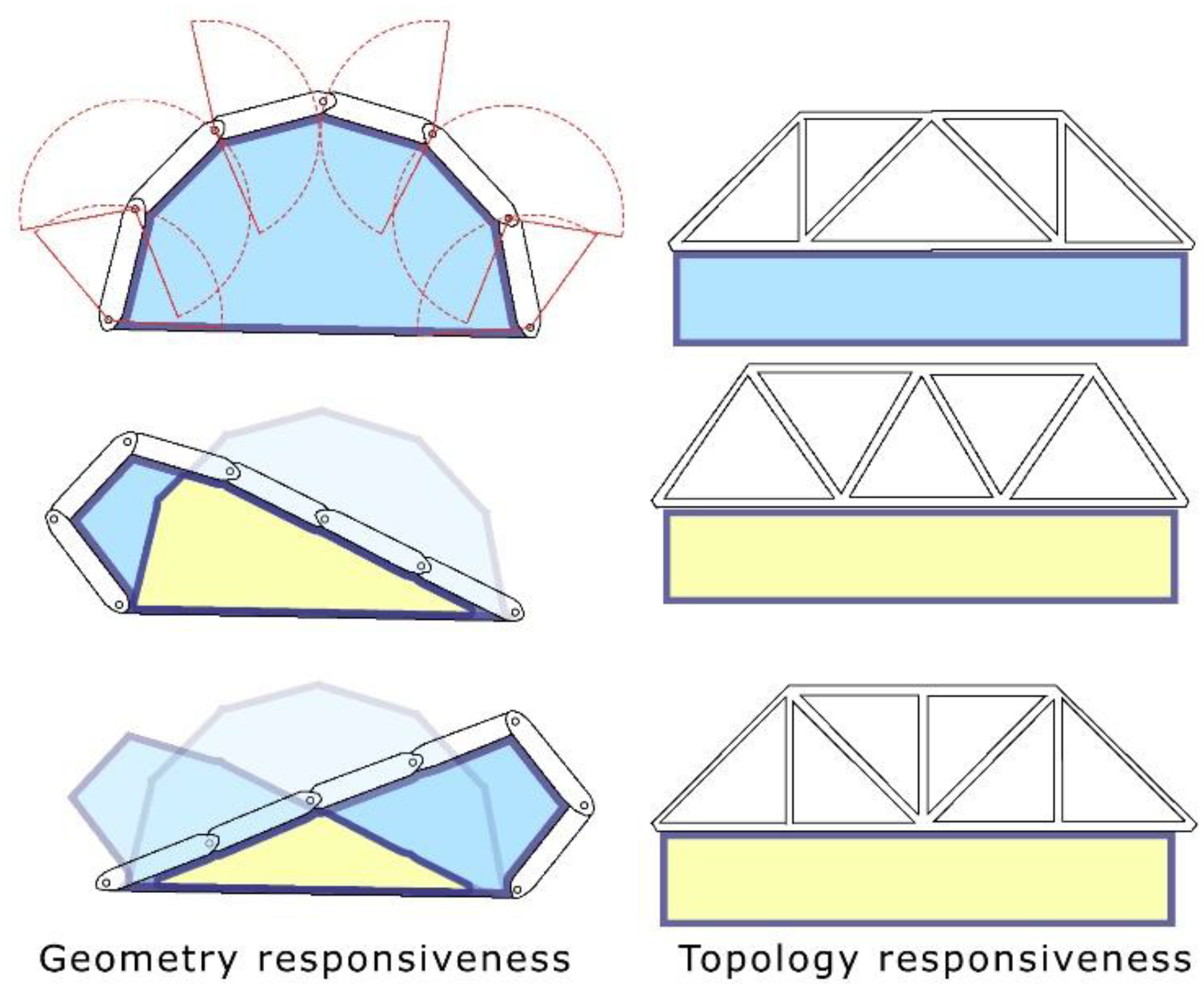
Figure 2.
Development Process of the Generalized Grasshopper Model and the Geometrical CAD Model.
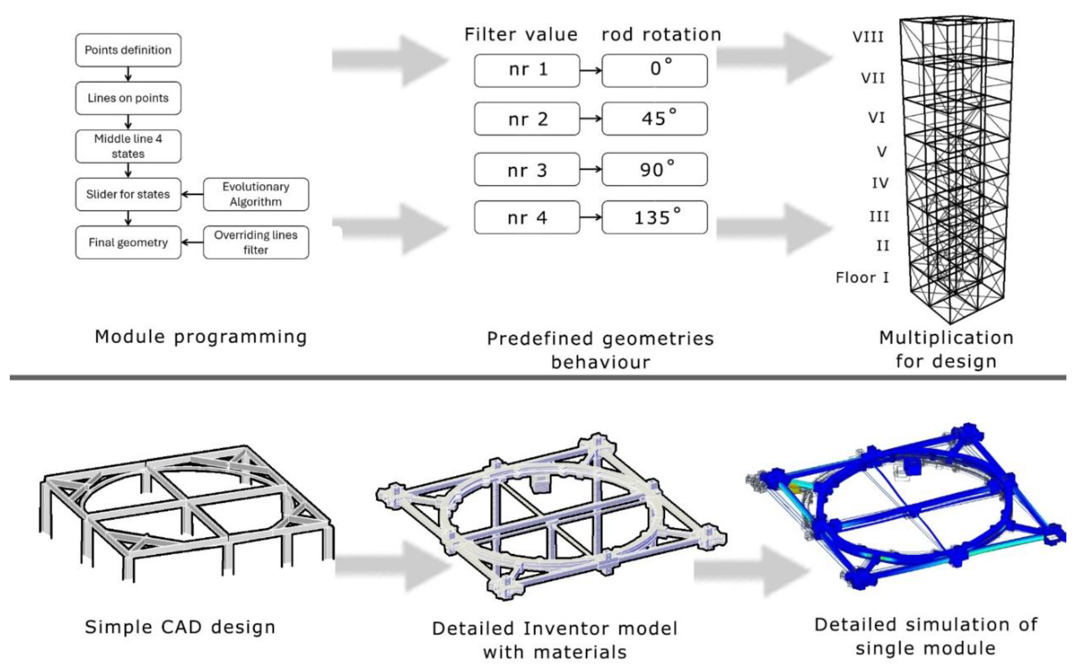
Figure 3.
Preparation for evaluation of applicability of the responsiveness form in a given type of structure.
Figure 3.
Preparation for evaluation of applicability of the responsiveness form in a given type of structure.
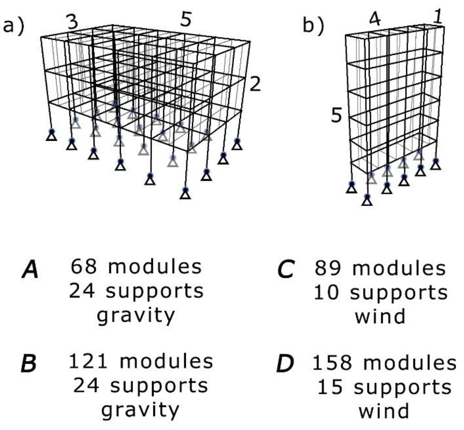
Figure 4.
Three types of bracing were considered: Type A, most effective for low horizontal loads, Type B, suitable for tall structures requiring simple bracing, and Type C, a topologically optimized model that maximizes load distribution and structural performance.
Figure 4.
Three types of bracing were considered: Type A, most effective for low horizontal loads, Type B, suitable for tall structures requiring simple bracing, and Type C, a topologically optimized model that maximizes load distribution and structural performance.
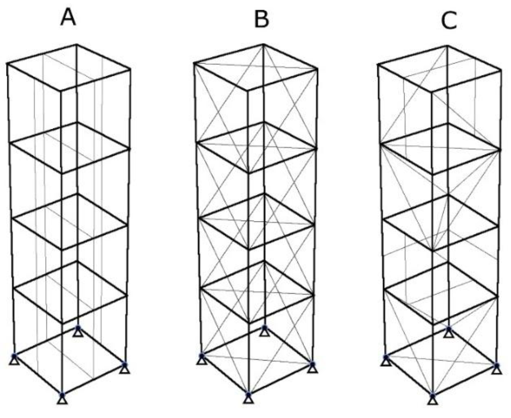
Figure 5.
The presentation illustrates the magnified deformation of the structure under lateral forces, as shown in the graphic. The magnitude of these deformations increases with height, following proposed load case.
Figure 5.
The presentation illustrates the magnified deformation of the structure under lateral forces, as shown in the graphic. The magnitude of these deformations increases with height, following proposed load case.
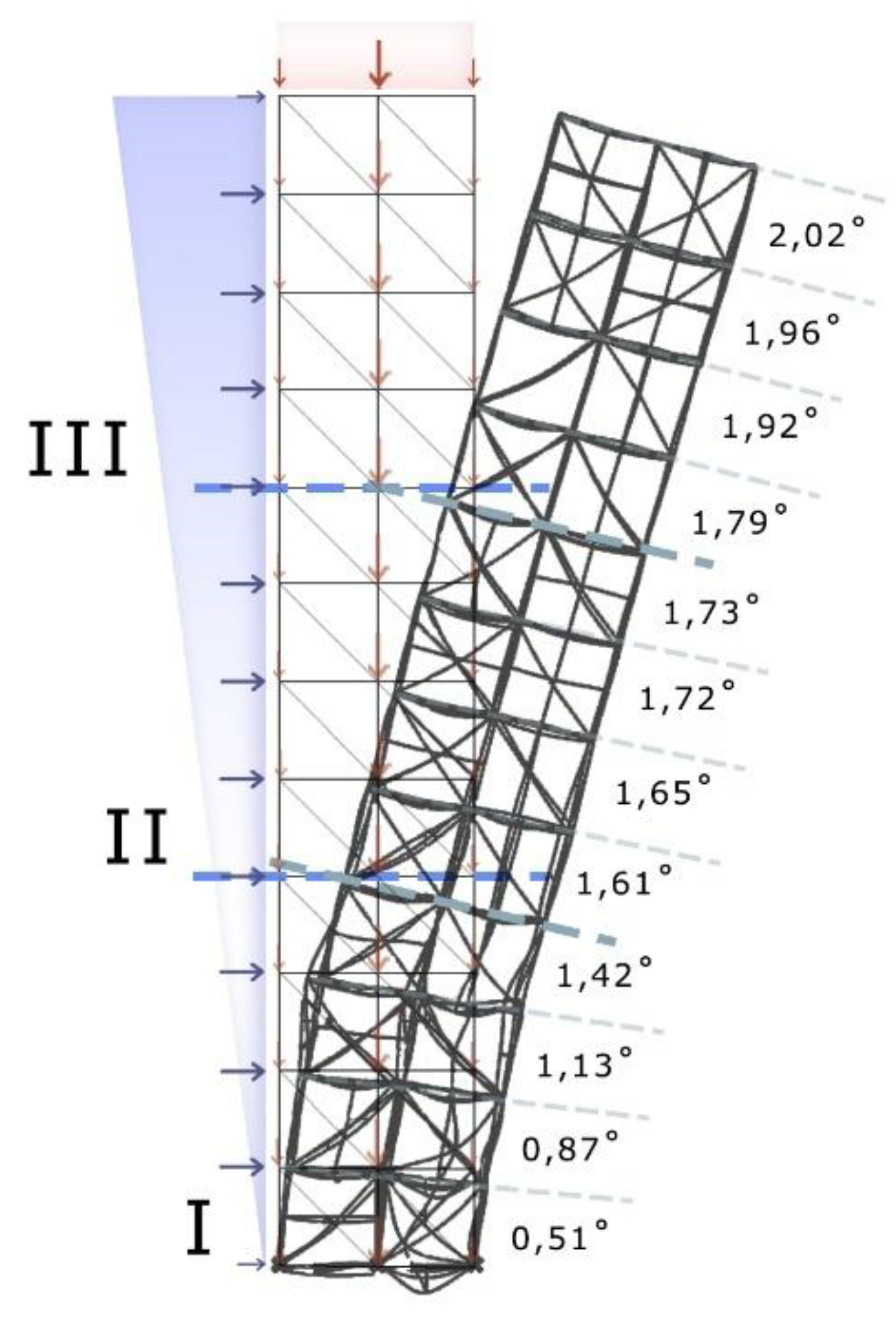
Figure 6.
Distribution of the proportion of all bars in the relevance to deformation.
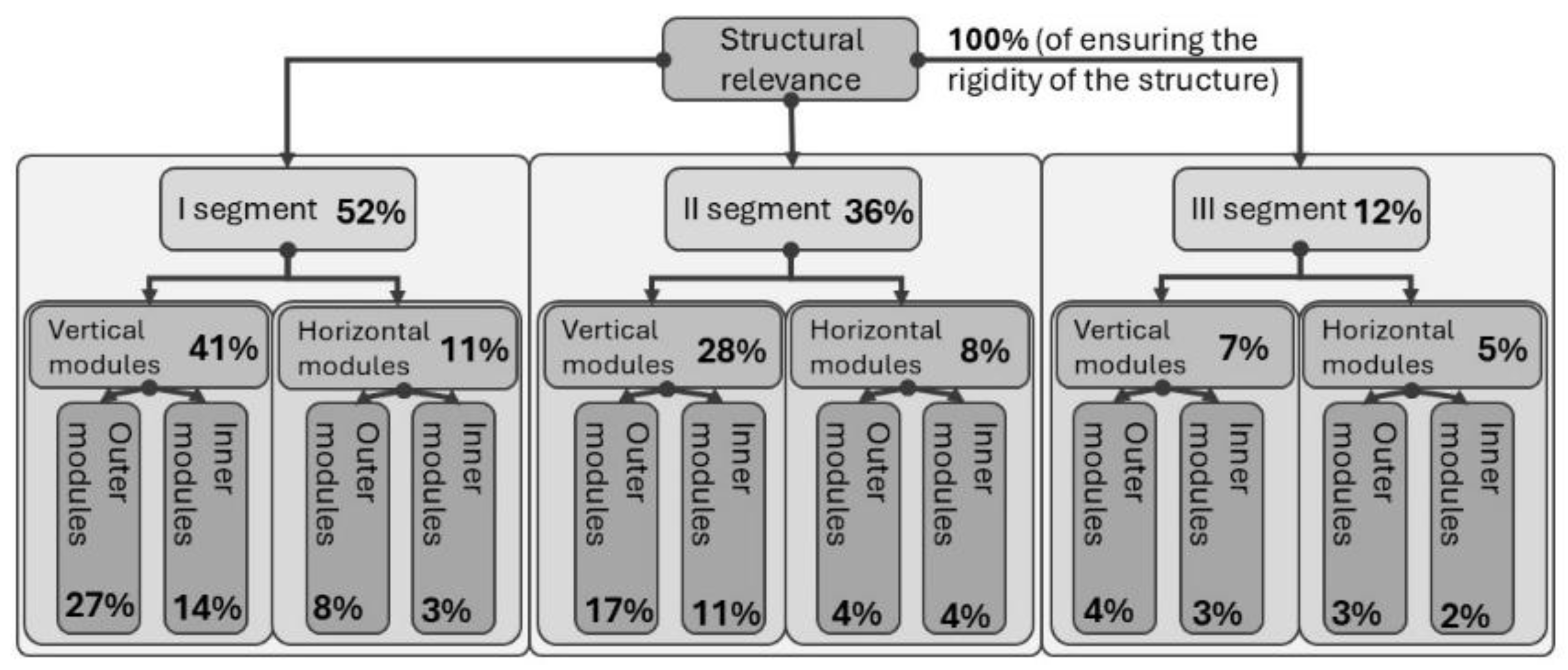
Figure 7.
The division of the structure into sections is presented. The only model that contains all sections is the 3x3x12 structure.
Figure 7.
The division of the structure into sections is presented. The only model that contains all sections is the 3x3x12 structure.
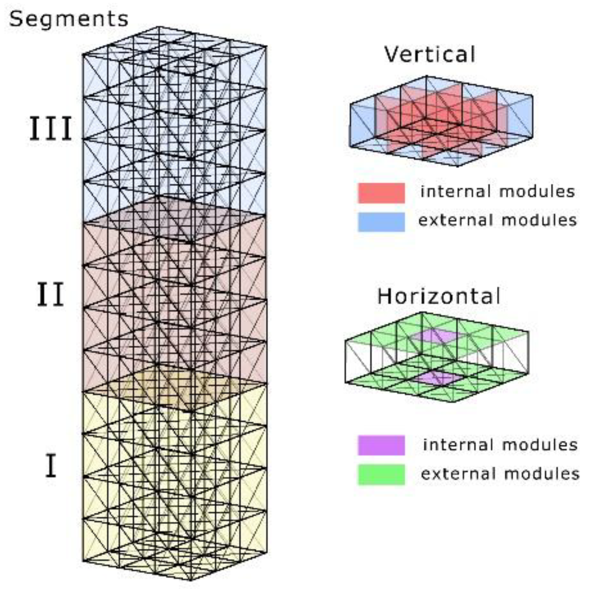
Figure 8.
The calculated significance boundaries for the individual sections of the structures. The green value represents the upper boundary (Q3), while the red value indicates the lower boundary (Q1).
Figure 8.
The calculated significance boundaries for the individual sections of the structures. The green value represents the upper boundary (Q3), while the red value indicates the lower boundary (Q1).
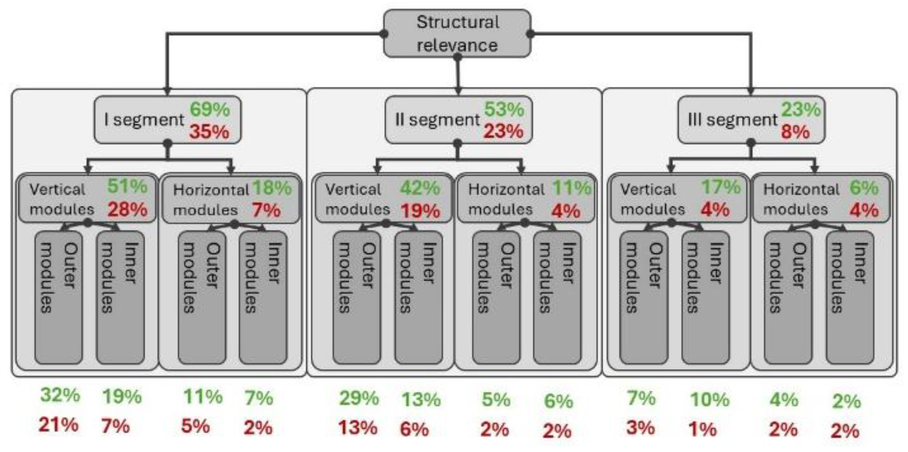
Figure 9.
Presentation of the Geometrical Model with Functionality and Breakdown into Assembly Components.
Figure 9.
Presentation of the Geometrical Model with Functionality and Breakdown into Assembly Components.
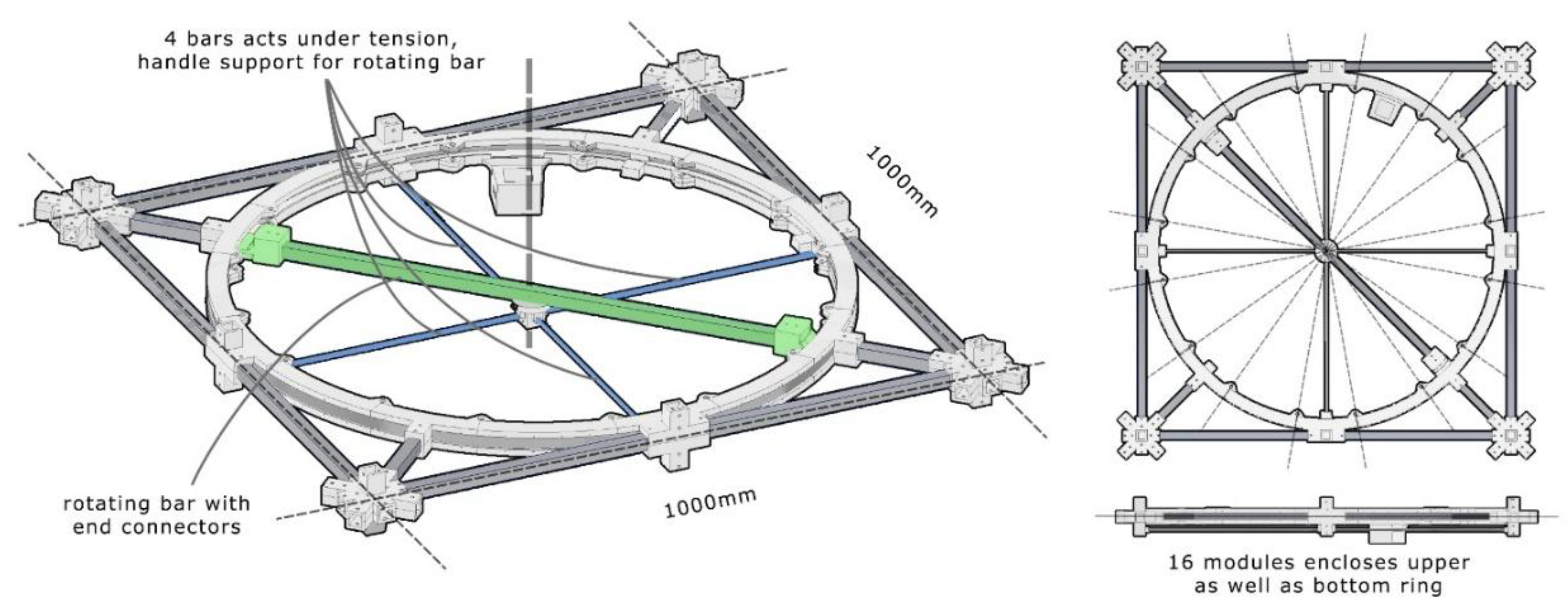
Table 2.
summary of load cases for the tests to be carried out.
| Direction of force | Case 1 | Case 2 | Case 3 | Case 4 | Case 5 | Case 6 | Case 7 |
| Force values proportion according to base value of 0,44kN/m2 | |||||||
| X | 0 | -0,1 | 0 | -0,1 | -0,5 | 0 | -0,5 |
| Y | 0 | 0 | -0,1 | -0,1 | 0 | -0,5 | -0,5 |
| Z | -1 | -1 | -1 | -1 | -1 | -1 | -1 |
Table 3.
Results of topology adaptation to different load cases. Green values indicates most effective configurations.
Table 3.
Results of topology adaptation to different load cases. Green values indicates most effective configurations.
| Direction of force | X=0 | X=-0,1 | X=0 | X=-0,1 | X=-0,5 | X=0 | X=-0,5 |
| Y=0 | Y=0 | Y=-0,1 | Y=-0,1 | Y=0 | Y=-0,5 | Y=-0,5 | |
| Z=-1 | Z=-1 | Z=-1 | Z=-1 | Z=-1 | Z=-1 | Z=-1 | |
| 1 | 144,36 | 5129,09 | 4812,94 | 7029,36 | 25637,44 | 24052,52 | 35140,98 |
| 175,25 | 3805,73 | 3795,26 | 6002,07 | 19638,92 | 19935,73 | 28861,46 | |
| 1x1x4 | 144,36 | 3439,79 | 3417,49 | 4867,52 | 17301,65 | 17262,05 | 24993,21 |
| 1,00 | 0,90 | 0,90 | 0,81 | 0,88 | 0,87 | 0,87 | |
| 2 | 232,39 | 13823,58 | 12877,52 | 18888,24 | 69108,50 | 64377,64 | 94434,34 |
| 291,03 | 10539,52 | 9387,14 | 14462,95 | 52964,54 | 53196,13 | 71427,05 | |
| 1x1x8 | 232,39 | 8167,18 | 7959,67 | 11479,70 | 40100,78 | 40152,45 | 58219,39 |
| 1,00 | 0,77 | 0,85 | 0,79 | 0,76 | 0,75 | 0,82 | |
| 3 | 489,64 | 14782,73 | 16257,17 | 21969,51 | 73882,15 | 81076,84 | 109711,0 |
| 611,83 | 9521,42 | 8937,13 | 15186,06 | 47396,38 | 51285,73 | 62853,85 | |
| 1x1x12 | 489,64 | 6689,00 | 6199,62 | 9288,49 | 32994,05 | 33087,73 | 47168,73 |
| 1,00 | 0,70 | 0,69 | 0,61 | 0,70 | 0,65 | 0,75 | |
| 4 | 116,44 | 1161,26 | 1387,79 | 1805,05 | 5789,79 | 6916,03 | 9017,46 |
| 148,77 | 156,55 | 157,85 | 165,15 | 267,89 | 319,34 | 384,51 | |
| 2x2x4 | 116,44 | 115,14 | 113,74 | 123,42 | 247,19 | 276,67 | 349,57 |
| 1,00 | 0,74 | 0,72 | 0,75 | 0,92 | 0,87 | 0,91 | |
| 5 | 213,26 | 4915,34 | 5830,34 | 7621,44 | 24554,32 | 29135,35 | 38095,15 |
| 281,85 | 692,79 | 701,05 | 958,78 | 3188,88 | 3203,43 | 4545,69 | |
| 2x2x8 | 213,26 | 588,20 | 538,27 | 693,43 | 2636,86 | 2813,78 | 3224,99 |
| 1,00 | 0,85 | 0,77 | 0,72 | 0,83 | 0,88 | 0,71 | |
| 6 | 356,890 | 12072,179 | 14133,992 | 18576,793 | 60319,125 | 70640,410 | 92867,867 |
| 503,118 | 7948,585 | 7948,585 | 11286,000 | 39507,731 | 39507,731 | 56169,282 | |
| 2x2x12 | 356,890 | 2607,437 | 2594,374 | 3621,335 | 34164,963 | 32402,671 | 48536,532 |
| 1,00 | 0,33 | 0,33 | 0,32 | 0,86 | 0,82 | 0,86 | |
| 7 | 121,18 | 1148,31 | 1398,14 | 1802,63 | 5725,46 | 6976,10 | 9005,08 |
| 156,26 | 201,67 | 192,42 | 230,97 | 430,23 | 367,91 | 553,47 | |
| 3x3x4 | 121,18 | 115,67 | 122,86 | 118,54 | 240,74 | 257,61 | 326,62 |
| 1,00 | 0,57 | 0,64 | 0,51 | 0,56 | 0,70 | 0,59 | |
| 8 | 226,58 | 4740,99 | 5757,82 | 7451,50 | 23685,29 | 28777,16 | 37245,02 |
| 522,21 | 929,84 | 929,84 | 1147,02 | 2906,58 | 2906,58 | 3788,48 | |
| 3x3x8 | 226,58 | 334,10 | 350,45 | 433,26 | 1902,76 | 1832,98 | 2347,57 |
| 1,00 | 0,36 | 0,38 | 0,38 | 0,65 | 0,63 | 0,62 | |
| 9 | 388,03 | 11265,70 | 13570,78 | 17623,75 | 56289,68 | 67827,87 | 88101,54 |
| 1116,82 | 2925,35 | 2925,35 | 3758,58 | 11132,76 | 11132,76 | 14675,63 | |
| 3x3x12 | 388,03 | 1539,83 | 1802,14 | 2047,96 | 7520,42 | 7402,63 | 10782,18 |
| 1,00 | 0,53 | 0,62 | 0,54 | 0,68 | 0,66 | 0,73 |
Table 4.
Rotation angles for individual segments. An uneven upward trend is observed.
| Maximum angles of rotation of elements at given levels for a 3x3x12 structure | |
| Level | Rotation in degrees [°] |
| 1 | 0,08 |
| 2 | 0,19 |
| 3 | 0,35 |
| 4 | 0,62 |
| 5 | 0,97 |
| 6 | 1,62 |
| 7 | 3,15 |
| 8 | 3,95 |
Table 5.
Deflection results for different load cases in accordance to different load case focus of evolutionary algorithm.
Table 5.
Deflection results for different load cases in accordance to different load case focus of evolutionary algorithm.
| universal model results | Load case | ||||||||||||||
| 0 | 1 | 2 | 3 | 4 | 5 | 6 | |||||||||
| 576,051341 | deflection after modification (mm) | 0 | 429 | 693 | 2157 | 2162 | 573 | 965 | 737 | ||||||
| 575,318276 | 1 | 833 | 432 | 641 | 661 | 578 | 943 | 722 | |||||||
| 310,557294 | 2 | 374 | 335 | 282 | 284 | 366 | 275 | 283 | |||||||
| 310,23089 | 3 | 379 | 334 | 284 | 284 | 369 | 274 | 284 | |||||||
| 754,242227 | 4 | 876 | 765 | 2358 | 2361 | 580 | 1481 | 964 | |||||||
| 309,793084 | 5 | 375 | 333 | 283 | 285 | 364 | 274 | 284 | |||||||
| 311,00566 | 6 | 378 | 336 | 283 | 284 | 370 | 275 | 284 | |||||||
Table 6.
Coefficients of effectiveness calculated as proportion of topologically responsive model to universal static one according to Table 5.
Table 6.
Coefficients of effectiveness calculated as proportion of topologically responsive model to universal static one according to Table 5.
| Load case | ||||||||||||||
| 0 | 1 | 2 | 3 | 4 | 5 | 6 | ||||||||
| deflection after modification (mm) | 0 | 0,74 | 1,20 | 3,74 | 3,75 | 0,99 | 1,67 | 1,28 | ||||||
| 1 | 1,45 | 0,75 | 1,11 | 1,15 | 1,00 | 1,64 | 1,26 | |||||||
| 2 | 1,21 | 1,08 | 0,91 | 0,92 | 1,18 | 0,88 | 0,91 | |||||||
| 3 | 1,22 | 1,08 | 0,92 | 0,92 | 1,19 | 0,88 | 0,92 | |||||||
| 4 | 1,16 | 1,01 | 3,13 | 3,13 | 0,77 | 1,96 | 1,28 | |||||||
| 5 | 1,21 | 1,07 | 0,91 | 0,92 | 1,18 | 0,88 | 0,92 | |||||||
| 6 | 1,21 | 1,08 | 0,91 | 0,91 | 1,19 | 0,88 | 0,91 | |||||||
Disclaimer/Publisher’s Note: The statements, opinions and data contained in all publications are solely those of the individual author(s) and contributor(s) and not of MDPI and/or the editor(s). MDPI and/or the editor(s) disclaim responsibility for any injury to people or property resulting from any ideas, methods, instructions or products referred to in the content. |
© 2025 by the authors. Licensee MDPI, Basel, Switzerland. This article is an open access article distributed under the terms and conditions of the Creative Commons Attribution (CC BY) license (http://creativecommons.org/licenses/by/4.0/).
Copyright: This open access article is published under a Creative Commons CC BY 4.0 license, which permit the free download, distribution, and reuse, provided that the author and preprint are cited in any reuse.


