
Submitted:
27 March 2025
Posted:
28 March 2025
You are already at the latest version
Abstract
One of nuclear power’s primary detractors is the unique environmental challenge and impact of radioactive wastes generated during fuel cycle operations. A key benefit of spent fuel reprocessing (SFR) are reductions in primary high active waste (HAW) masses, volumes, and lengths of radiotoxicity, at the expense of secondary waste generation and high capital and operational costs. By employing advanced waste management and resource recovery concepts in SFR beyond the existing standard PUREX process, such as minor actinide and fission product partitioning, these challenges could be mitigated, alongside further reductions in HAW volumes, masses, and duration of radiotoxicity. This work assesses various current and proposed SFR and fuel cycle options with a focus on primary waste outputs and the additional energy that could be generated by the reprocessing of high-burnup PWR fuel from Gen III(+) reactors, using a simple fuel cycle model. The effects of 5- and 10-year spent fuel cooling time before reprocessing are explored. We demonstrate that longer cooling times are preferable in all cases except for where short-lived isotope recovery may be desired, and that the partitioning of high heat fission products could allow for the reclassification of traditional raffinates to intermediate level waste. Highly active waste volume reductions approaching 50% vs. PUREX raffinate could be achieved in single target partitioning of the inactive and low-active rare earth elements, and the need for geological disposal potentially mitigated completely if high heat nuclides are separated and utilised.
Keywords:
spent nuclear fuel
; waste to resource
; waste management
; resource recovery
; nuclear fuel cycle
; spent fuel reprocessing
; partitioning and transmutation
; circular economy
; sustainability
1. Introduction
Despite the potential to generate vast quantities of low-carbon energy, widespread adoption of nuclear power is hampered by high costs, and concerns over the generation, processing, and disposal of vast quantities of many and varied past, present, and future radioactive wastes generated in fuel cycle operations (WNA, 2022), alongside overall negative public perception arising from these and other factors, such as accidents (Holdsworth and Ireland, 2024; Boscarino 2019). Technologies such as spent nuclear fuel reprocessing (SFR) are capable of reducing the radiotoxicity and volume of hazardous material for disposal in addition to other nuclear fuel cycle (NFC) efficiency benefits (IAEA, 2008), but high costs and proliferation concerns limit wider uptake of these operations. Reducing the costs of SFR and decreasing the waste volumes which arise from the NFC are two of the primary drivers in current fuel cycle research as interest in nuclear power increases in the face of increasing climate changes and other global challenges such as materials shortages (Holdsworth and Ireland, 2024).
Nuclear wastes arising from NFC operations occur as a wide range of forms and hazard classifications, the definitions of which vary appreciably from country to country (IAEA, 2022). For the purposes of this work, we shall consider the following:
- High-level wastes (HLW) are typically defined as “appreciably heat generating”, meaning that active cooling is often required. In Germany, this means a heat output of > 200 W/m3 (IAEA, 2022), which serves as a useful definition for this work. HLW includes materials such as spent nuclear fuel (SNF), reprocessing raffinates, some activated structural materials, etc, which must be handled remotely at all times due to their intense radiation fields which are extremely hazardous if not lethal to unprotected humans after even short exposure (IAEA, 2022). These wastes are often vitrified for long-term storage or disposal in a geological disposal facility (GDF), the latter of which has yet to be commercially realised anywhere at the time of writing (South Copeland, 2024).
- Intermediate-level wastes (ILW) includes materials such as the irradiated (zircalloy) cladding and structural elements from SNF assemblies which are not appreciably heat-generating but nonetheless still highly radioactive. These require remote handling in shielded hot cells, but in contrast to HLW are typically prepared and stored for disposal in a cemented form without the necessity for continuous active cooling. Under UK legislation, ILW is defined as “neither HLW or (very) low level waste”.
- Low-level wastes (LLW) and very low-level wastes (VLLW) are of sufficiently low activity that they can be handled outside hot cells, and include materials such as contaminated PPE, demolition rubble from nuclear facilities and some peripheral nuclear plant hardware.
Short of the questionably-efficient transmutation to lower-level wastes in a reactor (Sun et al, 2023), nuclear wastes cannot be removed from existence, merely separated and/or partitioned from one place to another with varying degrees of difficulty. One detractor that could be leveled against the nuclear industry is that any material originating from fission is deemed to be harmful, regardless of the level of activity present, if any, to the detriment of recovering potential resources present therein (Holdsworth et al, 2023; Allison, 2011). Partitioning and/or recovery of certain wastes for use could, however, lead to numerous and significant benefits to the NFC, as will be discussed later (Forsberg, 2000; Vandenborre, 2024).
This is evidenced by SNF containing a large number of inactive, naturally-occurring isotopes produced inherently during fission which otherwise represent scarce and highly useful materials such as the platinum group metals (PGMs), rare earth elements (REEs), and noble gases (NGs), alongside a significant number of harmful but also potentially useful isotopes (Holdsworth et al, 2023). The recovery of these materials from SNF as a value stream was proposed as far back as the 1960s (Rohrnmann, 1965), but is only now receiving significant attention in light of increased interest in nuclear power (Bond et al, 2019; Holdsworth et al, 2019a and 2019b; Holdsworth et al, 2020), though attitudes to the use of materials sourced from nuclear origins must change for greater acceptance (Allison, 2011).
The current PUREX (plutonium uranium reduction extraction) process, the gold-standard in SFR employed around the world, only extracts U and Pu from SNF, leaving the fission products (FPs) and minor actinides (MAs) as wastes for disposal (IAEA, 2008; Baron et al, 2019). This results in a marked reduction in waste volume, a significant reduction in mass relative to the disposal or storage of whole SNF assemblies, and a decrease in length of radiotoxicity from Pu by several orders of magnitude (see Figure 1) (IAEA, 2008). Ideally, the Pu and U recovered are recycled for further energy generation as MOX (mixed oxide) fuel, rather than being stored. Developments of this, including the SANEX (selective actinide extraction) and GANEX (grouped actinide extraction) further partition the MAs (Np, Am, Cm, Bk, Cm) from SNF raffinate post-U and Pu extraction to further reduce the length of radiotoxicity (see Figure 1) by fissioning these species in fast-spectrum reactors (IAEA, 2008; Baron et al, 2019; Poinssot et al, 2012).
Further to this, an advanced concept whereby the high heat radionuclides (HHRs, the FPs 134Cs, 137Cs, and 90Sr), the primary sources of radioactivity in SNF HLW, are selectively partitioned during reprocessing for separate storage and/or disposal (Forsberg, 2000). This could potentially allow for reclassification of the remaining waste from HLW to ILW (Bond et al, 2019), and some recent effort towards achieving this goal, with potential further benefits for SFR operations by addressing current operational challenges and high costs, have been undertaken by the authors (Bond et al, 2019; Holdsworth et al, 2019a and 2019b; Holdsworth et al, 2020),). More recently, it has been proposed to utilise SNF for production of H2 via radiolysis of water with a TiO2 catalyst; separation and concentration of HHRs to facilitate this would likely increase the effectiveness of the process, which is potentially capable of generating the world’s entire demand for hydrogen from current SNF stockpiles (Vandenborre, 2024). This would effectively turn materials considered a hazardous and inconvenient waste into a true resource and offset the high costs of the NFC.
In a similar vein, some recent research has been directed at the recovery of valuable and naturally scarce FPs from SNF during SFR to offset the high costs of these operations, providing sovereign sources of finite materials which are in high industrial demand (Bourg and Poinssot, 2017; Holdsworth et al, 2023; Hodgson et al, 2023, Holdsworth et al, 2025). This would, potentially, allow the NFC to become part of a great materials circular economy and significantly more sustainable in its operation (Holdsworth et al, 2023; Holdsworth and Ireland, 2024; Holdsworth et al, 2025). Categories of material proposed for extraction includes the platinum group metals (PGMs – Ru, Rh, Pd, Ag) and rare earth elements (REEs – Y, La-Tb); additionally, several useful radioisotopes are present in SNF and can potentially be extracted (e.g. 90Sr/90Y, 137Cs, 85Kr, etc.) (Bourg and Poinssot, 2017; Holdsworth et al, 2023; Hodgson et al, 2023; Holdsworth et al, 2025).
The open literature contains comparatively little discussion on the impact of these processes (and combinations thereof) on reprocessing waste impacts and the NFC in general. Consequently, we present an assessment of these process impacts in the context of modern NFCs. This uses a simulated composition for high-burnup (HBU, 60 GWd/tHM) Gen III(+) pressurised water reactor (PWR) SNF (UO2, 5% initial 235U) from a reactor such as the EPR (European Pressurised water Reactor) (Ando and Takano, 1999). This fuel will be assumed to have been cooled for periods of either 5 or 10 years post-irradiation before reprocessing. Several options, including the open fuel cycle, are explored for comparative purposes. Using these values, we explore the effects of different reprocessing separation options on primary HLW volumes, masses, and activities from these operations. Although our source data (Ando and Takano, 1999) includes information for comparative MOX SNF, we do not consider the use of Pu multi-recycle in this work (Taylor et al, 2024; Taylor et al 2022a and 2022b), although this may be investigated in future publications.
2. Methodology
2.1. Data Sources and Calculations
The isotopic composition of the virtual SNF system was acquired from the work of Ando and Takano, pp. 121-135, using the 5- and 10-year post-reactor values provided (Ando and Takano, 1999). These values were originally generated by the ORIGEN fuel performance code, amongst others, and represent one of the most comprehensive available sources of SNF compositions. These values were used to develop a statistical calculator in a previous work (Holdsworth et al, 2021).
Additional isotopic data (half-lives, specific activities, decay energies) was acquired from the IAEA isotope browser (IAEA, 2025), NRC (NRC, 2025), and WISE Uranium project (WISE, 2024) databases. The complete list of isotopes included in the model for this work are presented in Tables S1 (actinides and daughters) and S2 (fission products); the full dataset is available in the electronic supplementary information (ESI) file. Some values were approximated for long-lived species where specific data was not available, and data for some isotopes is not included in the original source; some best-guess assumptions were made regarding the identities of undefined isotopes from the primary dataset, as outlined in the ESI.
Please note that the dataset used for this work does model a simplified representation of counterion (i.e. oxide, O2-) activation (which starts from 100% 16O, rather than natural composition) (Ando and Takano, 1999). Furthermore, it does not provide information regarding ternary fission products, nor is alpha decay or neutron emission and capture beyond reactor operation modeled (Ando and Takano, 1999). These isotopes, being predominantly volatile (isotopes of H, He, Li, Be, B, C, N, O, F, and Ne), are not discussed further.
The specific decay heats for each isotope were calculated as a product of specific activity (Bq/g), the concentration (g/tHM), and the decay energy (keV). These isotope-specific heating powers were then summed to express a value per (metric) tonne of spent fuel. Please note than unlike our previous work (Holdsworth et al, 2021), where the decays of short-lived daughters (e.g. 90Y and 106Rh) were treated as being part of their parent for calculation purposes, here they are measured under the element of the intermediate with the exception of 137mBa and the daughter products of nuclides undergoing double β- decay.
The decay energies used for these calculations (Qα/Qβ/QEC, etc.) represents the total potential decay energy for each isotope (Holdsworth et al, 2021). While this is relatively accurate for nuclides that decay via alpha decay, this tends to somewhat overestimate decay heats for those which decay via beta-gamma emission and/or electron capture, as in these processes, a portion of the energy is lost to non-interacting antineutrino emission (Holdsworth et al, 2021). For the purposes of this work, however, we consider these values to be acceptable conservative estimates of true decay heat and radioactivity values. These estimates could be improved by accounting for minor decay branches, but these would render the calculations far more complex for limited benefit, and as such are omitted from this work.
2.2. Consideration of Separations Operations and Processes
For simplicity, we consider all physical and chemical separations that occur in a reprocessing facility to be simplified and idealised “black box” operations that function with 100% efficiency. While this is not wholly representative of real-world processes, most operators would aim to achieve near-quantitative recovery of target elements to justify the costs of such operations. All operations are treated in this manner, including the head-end operations of reprocessing. This includes head end processes that produce two primary waste streams, volatile fission products (Br, Kr, I, Xe) (Collins et al, 2011; Plumb, 1984) and generic ILW composed of fuel cladding and fuel assembly hardware. The former of these is counted as a dedicated waste stream in each scenario, while the ILW stream must be discounted as it is dominated by activation products that are out of the scope of our source dataset. Furthermore, the concentration, activity, and decay heat of U daughters (Pa, Th, Ac, Ra, Fr, Rn, At, Po, Bi, and Pb) are counted with U itself as, while these would be separated from the U during chemical reprocessing operations, these species reform a secular equilibrium over time during storage through natural decay of U. Conceptual head-end technologies for reprocessing, such as voloxidation, which have a significant impact on the routing of many FPs, are not discussed as these add further complication beyond the scope of this work. The simulated vitrified waste outputs from this work assume a glass density of 3.33 g/cm3 and a waste loading of 20 wt% (accounting for oxides as the chemical form of waste elements, etc.) (Connelly et al, 2011; Harrison, 2014).
2.3. Spent Fuel Reprocessing Scenarios
We consider several NFC base-cases and more conceptual scenarios incorporating a mixture of proposed and extant flowsheets for the reprocessing of SNF. A comprehensive review of the maturity of most of these technologies can be found in a recent review (Baron et al, 2019). These scenarios are:
2.3.1. Scenario 1: The Open Fuel Cycle
The least-preferable approach to handling spent fuel is direct disposal following several decades of first wet storage and then dry-cask storage. This essentially removes valuable fissile and fertile materials from availability, alongside many other naturally-scarce resources which have been identified (Bourg and Poinssot, 2017; Holdsworth et al, 2023). In this case, the mass and volume of material for disposal is at least one order of magnitude higher than if any separative operations (outlined below) are performed on SNF. For our purposes, we shall assume the disposal of entire PWR SNF bundles in a hypothetical GDF.
2.3.2. Scenario 2: UREX for Waste Volume Reduction and/or U Re-Enrichment
One proposed approach to handling the volume of SNF currently in wet and dry storage around the world is to chemically separate and perhaps reuse U, as the main component of SNF, from the remaining constituents which are then disposed of as vitrified waste (Vandegrift et al, 2004). This would use an adaption of the established solvent-extraction-based PUREX process commonly dubbed UREX (uranium extraction) without co-extraction of Pu, and with disposal of the remaining components. A great many variations on the UREX process could further treat the waste raffinates to recover desirable materials through operations such as TALSPEAK and derivatives, none of which have yet made it to commercial operation (Baron et al, 2019) and the discussion of which is largely beyond the scope of this work. The materials for disposal in this scenario will be considered as 20 wt% vitrified composites in glass (Harrison, 2014).
2.3.3. Scenario 3: The Traditional PUREX Process
Representing the current standard SNF reprocessing flowsheet around the world, the PUREX process was initially developed to recover Pu for nuclear weapons purposes. In modern times, however, this highly-effective flowsheet is used to reprocess SNF by selectively separating the U and Pu present for use as MOX for further energy generation in modern reactors (Baron et al, 2019). The HLW raffinate materials for disposal in this scenario will be considered as 20 wt% vitrified composites in glass (Harrison, 2014).
2.3.4. Scenario 4: PUREX with Minor Actinide Separations, GANEX, or UREX Versions
The next evolution of the PUREX process proposed for several decades involves the use of additional separations process or alternative flowsheets to partition the MAs (Np, Am, Cm) during operations, providing a dedicated feed of these materials for storage and later transmutation in a (fast spectrum) reactor. This would serve to reduce the length and severity of radiotoxicty of reprocessing raffiantes relative to PUREX. While there are several methods by which this could be achieved, such as the addition of the SANEX process to PUREX, the use of the dual-stage GANEX flowsheet, or UREX plus the various proposed TALSPEAK and similar operations (Baron et al, 2019), these are all functionally similar and as such will be treated as achieving the same end result for our purposes. The materials for disposal in this scenario will be considered as 20 wt% vitrified composites in glass (Harrison, 2014).
2.3.5. Scenario 5a: U, Pu, and Minor Actinde Separations with HHR Removal
If the MAs are removed from SNF during reprocessing, the remaining highly-active raffinate raffinate contains only FPs, of which the primary sources of radioactivity are, depending on post-reactor cooling time, 134Cs, 137Cs, 90Sr (and 90Y), 106Ru (and 106Rh), 144Ce (and 144Pr), 147Pm, 154/155Eu, and 85Kr. Forsberg proposed the removal of the first three of these using selective separations as a means to reduce decay heat loads on repositories by using separate decay storage of these nuclides (Forsberg, 2000), though they could be utilised for a number of potential applications instead. The existing proposals to achieve this would extract Cs and Sr selectively from reprocessing highly active raffinates, following the extraction of U, Pu, and the MAs. Our own research has demonstrated that this could, in theory, be achieved prior to these operations, to the benefit of all downstream processes (Bond et al, 2019; Holdsworth et al, 2019a and 2019b; Holdsworth et al, 2020). The non-HHR materials for disposal in this scenario will be considered as 20 wt% vitrified composites in glass (Harrison, 2014), while the forms for the HHRs themselves require special consideration given the levels of decay heat produced when in a concentrated state (Forsberg, 2000).
2.3.6. Scenario 5b: U, Pu, and Minor Actinde Separations with PGM Recovery
As the PGMs are the most value elemental components of SNF after the actinides, recovering these during reprocessing could serve to offset a significant proportion of the high costs of these operations, as the concentrations of these elements in SNF are far higher than in any natural ore (Rohrmann, 1965). Proposals to achieve this have been proposed since the 1960s, but have seen more recent attention given geopolitical shifts, increasing demands for naturally-scarce materials, and a range of other factors. We shall consider the separation and recovery of Ru, Rh, Pd, and Ag from the highly active raffinate outputs of reprocessing, with disposal of the remaining FPs. The materials for disposal in this scenario will be considered as 20 wt% vitrified composites in glass (Harrison, 2014). The potential necessity for the decay storage or separated PGMs is also discussed.
2.3.7. Scenario 5c: U, Pu, and Minor Actinde Separations with REE Recovery
Similar to the PGMs, the REEs are naturally scarce, experiencing exponentially-increasing demands from modern high-technologies, and occur at high concentrations in SNF (Bourg and Poinssot, 2017; Ando and Takano, 1999; Holdsworth et al, 2023). As the majority of MA separations technologies also co-separate the chemically similar REEs before selectively stripping the lanthanides and actinides (Baron et al, 2019). As the REEs occur together naturally and are mined at scale around the world, technologies to separate these chemically similar elements using chromatographic approaches are robust and could be applied to REE streams from SNF reprocessing. Several of the REEs found in SNF possess no radioactive isotopes (when certain short-lived daughter nuclides are discounted) or are essentially non-radioactive, and as such, these could be used directly without the need for decay storage. The various options for the REE stream will be analysed. The materials for disposal in this scenario will be considered as 20 wt% vitrified composites in glass (Harrison, 2014).
3. Results and Discussion
Scenarios 1 to 4 represent the current implementations and state-of-the-art proposals for handling of SNF in the NFC. These, Scenario 4 in particular, provide the basis for the more advanced concepts discussed in Scenarios 5a to 5c, as we assume any new-build SFR plant will include, at a minimum, primary U and Pu and secondary MA separations.
3.1. Scenario 1: The Open Fuel Cycle
The least favourable approach to the NFC is the open fuel cycle (Figure 2), followed by the “wait and see” method used by a large number of nuclear-generating countries. Disposing of SNF directly after use, following a period of post-reactor cooling, is wasteful, inefficient and, in the long term, unsustainable (Holdsworth and Ireland, 2024). This also represents the least efficient disposal option in terms of waste mass and volume as, in addition to the bulk U component of SNF, all of the metallic components of the cladding and fuel assemblies are retained for disposal, in addition to the air gaps between fuel pins and necessary separation between bundles for appropriate cooling and for criticality safety. The proposed direct SNF bundle disposal approach proposed by several nations (Sweden, Finland) further uses alarming volumes of strategic materials such as copper, and as such is highly unfavorable, in addition to potentially requiring longer cooling times before final disposal (25-30 years) than reprocessed SNF wastes (5-10 years).
Using the values from Roddy et al (Roddy et al, 1986), a standard 17x17 PWR fuel assembly contains 461.4 kg of U as the initial heavy metal mass (as 523.4 kg of UO2), alongside 134.5 kg of zircalloy and other metals, occupying a nominal volume of 0.186 m3 externally. This means that per ton of initial heavy metal, a total of 1446 kg of mass must be disposed of, occupying a volume of at least 0.403 m3, and likely much more than this given the necessity to space fuel bundles for criticality and decay heat safety and the additional volume occupied by the waste disposal canisters: we can assume a value of at least double or triple this (based on the image from (Sky News, 2022)). The high density of U (present as UO2) is a major contributor to the wasteform physical properties in this scenario. The mass of the wasteform would also be significantly greater due to the volume of copper, steel, and/or concrete used to contain the fuel bundles.
Where disposal in a GDF is not implemented but instead the SNF is contained in dry casks for an extended period in the “wait and see” approach is more preferable, but still less than ideal as useful fissile and fertile nuclides are essentially removed from available supplies for the interim but could, at some cost, be recovered for later reprocessing.
3.2. Scenario 2: The UREX Process
The base UREX process (Figure 3) is an adaption of the PUREX process whereby Pu is not co-extracted alongside U in the primary solvent extraction operation, leaving a raffinate containing all the remaining components of SNF including all transuranics and FPs. This raffinate is then vitrified and containerized for storage until deep geological disposal in a GDF can be undertaken, while the U is either stored for disposal at a lower level classification, or could be re-enriched for further energy generation. The respective masses, activities, and decay heats of these two streams from our simulated HBU PWR SNF is presented in Table 1.
As can be seen from the results presented in Table 1, partitioning U from the remaining components of SNF using the UREX process would result in the removal of 92.39% of the initial heavy metal mass for final disposal. The U stream alone (assuming no additional mass from compounds of U) is off sufficiently low activity to be reclassified as ILW, while still containing 0.938% 235U – representing a more favourable feed for re-enrichment than natural U, should this approach be desired, or an appropriate isotopic mixture for fissioning in efficient reactors such as the CANDU design. These values do not appreciably change whether the SNF is cooled for 5 or 10 years before reprocessing. A reduction in activity would arise from the removal of U decay products, but these would begin to breed into the material upon storage.
The raffinate outputs from UREX represent 6.56% of the total initial heavy metal mass for disposal and practically all of the activity and decay heat. Cooling SNF for 10 years instead of 5 before reprocessing would result in a marked (35.3%) reduction in overall decay heat and thus solvent degradation and other operational challenges. If we assume that the conversion of the elements present in the raffinate to oxides would grant a loading in glass of 20 wt%, and a final wasteform density of 3.33 g/cm3, this means that per initial ton of heavy metal, 328 kg of vitrified HLW are produced, taking up a volume of 0.0984 m3, and with a corresponding specific heat output of 17.5 W/kg if cooled for 5 years or 11.3 W/kg if cooled for 10 years.
3.3. Scenario 3: The PUREX Process
The PUREX process (Figure 4) is the current gold-standard in SNF reprocessing and has been used for over six decades due to its effectiveness at selectively separating U and Pu from the MAs and nearly all FPs. PUREX would normally produce separate U and Pu feeds alongside a raffinate containing the FPs and MAs, but for the purposes of this work, we will assume that the Pu is co-partitioned with at least some U in order to maintain proliferation resistance (Baron et al, 2019). The raffinate output is, as above, vitrified and containerized for storage until deep geological disposal in a GDF can be undertaken, while the U and Pu would be converted to MOX for further energy generation. The respective masses, activities, and decay heats of these two streams from our simulated HBU PWR SNF is presented in Table 2.
Reprocessing HBU PWR SNF using the PUREX process would remove at least 93.6% of the initial heavy metal mass for final disposal. In this context, we will not consider the U+Pu stream to be a waste, but rather a potential resource for the generation of further energy. If all of the U present were partitioned with Pu, the total concentration present would be equivalent to 1.38% if reprocessed after 5 years cooling, and 1.35% after 10 years, due to the decay of some 350 g of fissile 241Pu. This presents a valid argument for the reprocessing of shorter-cooled (5 y) SNF for increased fuel cycle efficiency, given the higher fissile isotope content under these conditions and the general inefficiency of MA burning in thermal-spectrum reactors. Given the relatively low Pu + 235U content of the hypothetical fuel in this scenario, which could be effectively burned in a CANDU reactor or to lower burnups in a PWR, it would likely represent a more effective use of resources to partition a large proptortion of the U from the U+Pu feed and instead form higher Pu content MOX (7-8% iHM) capable of reaching the same burnups as the initial UO2 in Gen III(+) reactors. The excess U partitoned off in this manner is at the same enrichment as described above and suitable for re-enrichment for further power generation. It would be preferable to utilise any MOX produced as quickly as possible after reprocessing to mitigate the effects of 241Am ingrowth into the fuel.
The presence of Pu in the U+Pu feed significantly increases both the activity and decay heat relative to the UREX U feed (Table 1), primarily due to the decay of 238Pu, though as this material is not intended for disposal, we do not need to pay too much consideration to these values. The specific decay heats relative to the HLW raffinate are ~ 5 orders of mangnitude lower, primarily in the form of α-decay, though consideration would need to be paid to the significant neutron emission of 240Pu and 242Pu, the nuances of which are beyond the scope of this work.
The raffinate from PUREX represents 5.28% (5 year-cooled) or 6.31% (10 year cooled) of the total initial heavy metal mass for disposal, alongside the majority (~77%) of the activity and (91-94%) of the decay heat. As with UREX, cooling the SNF for 10 years instead of 5 before reprocessing results in a marked (37.1%) reduction in the decay heat of the HLW raffinate, and thus the potential radiolysis and other challenges induced during reprocessing. Assuming as with above a vitrified waste loading of 20 wt% and a final wasteform density of 3.33 g/cm3, this means that per initial ton of heavy metal, 264 or 266 kg of waste are produced after 5 and 10 years cooling respectively, with a volume of 0.0795 m-3. These would have a specific heat output of 20.6 or 12.8 W/kg if cooled for 5 or 10 years before reprocessing respectively.
3.4. Scenario 4: The PUREX Process with Minor Actinide Separations
The next evolution of SFR will likely build upon the PUREX process by addition of MA separations, based upon the last several decades of research and industrial interest (Baron et al, 2019). For the purposes of this scenario, we will assume a PUREX primary separation with a SANEX secondary separation removing the MAs (Np, Am, Cm, Bk, and Cf Figure 5), though variations on this, such as the UK’s conceptual Advanced PUREX process (which co-extracts Np with U and Pu for proliferation resistance) with an i-SANEX secondary separation (for Am and Cm), the European GANEX (U-only primary separation, transuranic secondary), or several of the more complex variations on the US UREX process functionally achieve the same goal of segregating all of the actinides from the FPs.
We would assume for the purposes of this advanced fuel cycle implementation that any MAs are transmuted in a fast-spectrum reactor (e.g. sodium- or lead-cooled fast reactor) while the U/Pu MOX produced could be used to drive either thermal or fast spectrum reactors or as fast reactor driver fuel; Np can further be used as effective driver fuel in concert with Pu in fast reactors. The data is presented in Table 3. For the purposes of this scenario, we will assume that the REE feed produced by most MA separative flowsheets is routed back into the HLW raffinate.
The values for the U+Pu feed produced in this scenario are identical to those for the PUREX scenario outlined above and as such do not require any further discussion.
The additional MA feed generated increases in magnitude with increasing cooling times, primarily due to the decay of 241Pu to 241Am far outstripping the decay of any other isotopes (Cm primarily). This represents one of the primary drivers for reprocessing SNF at a shorter cooling times as the fissile content is higher, although as discussed later, the impacts of 241Pu decay on further energy production is limited. The MA feed represents 0.18 and 0.22% of the total heavy metal mass at 5 or 10 years cooling time respectively, producing 19.25 or 22.25% of the activity, and 5.6 or 8.3% of the decay heat. If stored as dedicated MA oxides (MO2, assuming a MW of 275), these materials would produce 0.19 or 0.15 W/g after 5 or 10 years’ cooling respectively, the reduction primarily arising from the decay of 244Cm, but offset partially by increased 241Am concentrations. It is more likely, however, that these materials would be stored in a mixed oxide with U (typically 20% MAs) which would dilute the decay heat values by a factor of ~5 accordingly. Of necessary consideration, however, are the neutron emissions posed by Cm isotopes, which are significantly higher in magnitude than those of Pu and would perhaps necessitate only remote handling of Cm-containing fuel elements. This is, in part, the rationale in some nations for the development of Am-selective MA partitioning flowsheets for transmutation of only Am in fast spectrum reactors or accelerator driven systems (Abderrahim et al, 2020).
The removal of the MAs from the HLW raffinate serves to reduce the mass for disposal (relative to UREX and PUREX) to 5.1% of the total heavy metal mass while decreasing the both activity (75-78%) and decay heat (81-87%), depending upon cooling time. Reprocessing after 10 years instead of 5 years would result in a 39.5% reduction in HLW raffinate decay heat, an increase largely driven by the removal of the MAs. As with the other scenarios, if we assume a vitrified waste loading of 20 wt% and a final wasteform density of 3.33 g/cm3, this means that per initial ton of heavy metal, 254 kg of waste with a volume of 0.0762 m3. These waste outputs would have a specific heat output of 19.74 or 11.94 W/kg after 5 or 10 years of cooling, respectively.
3.5. Scenario 5a: High Heat Radionlucide Separations in PUREX with Minor Actinide Separations
The first of our novel scenarios is the addition of HHR separations to the PUREX+SANEX operations outlined above. Based upon our previous work (Bond et al, 2019; Holdsworth et al, 2019a and 2019b; Holdsworth et al, 2020), it is probable that these operations could be performed upstream of the primary and secondary separations via ion exchange processes, providing many benefits to operation and mitigations to operational challenges, as outlined in Figure 6. As the daughter products of 137Cs and 90Sr are key contributors to the decay heat of the HHRs, these values are counted with their parents for the purposes of this scenario. The feed masses and decay heat data is presented in Table 4.
The values for the PUREX and MA feeds in this scenario will be indentical to those presented above and as such warrant no further discussion. The separation of the HHRs Cs and Sr, however, significantly changes the considerations for raffinate handling in the back-end of reprocessing operations.
After five years of cooling, the Cs and Sr collectively represent 0.62% of the initial heavy metal mass for diposal, whilst producing 61% of the activity and 68.5% of the decay heat. By 10 years, the mass contribution has fallen to 0.58%, whilst the activity and decay heat contributions has increased to 71% and 78.1% respectively.
As concentrating this amount of radioactivity to pure elements would represent significant operational and safety challenges if improperly engineered (see What is Nuclear?, 2024), we can at this stage conclude that any wasteform, or wasteforms accommodating Cs and/or Sr isolated from SNF would have to be sufficiently “dilute”: the specific decay heat of an elemental Cs-Sr wasteform would be 643 mW/g at 5 years cooling and 505 mW/g at 10 years, around that of pure elemental 238Pu. At such “screaming” levels of activity, processes would require specific arrangements for active cooling and completely remote handling. The details of these arrangements are beyond the scope of this work, and have been discussed at length in our previous publications and presentations (Bond et al, 2019; Holdsworth et al, 2019a and 2019b; Holdsworth et al, 2020).
This approach would also present the opportunity to isolate a portion of the 137Cs or 90Sr and their daughters, both of which are useful isotopes in their own right (Holdsworth et al, 2023). Beyond this, recent research has the potential for H2 production via water radiolysis, which could meet world demand at the time of writing from the radioactivity of present SNF stockpiles (Vandenborre et al, 2024). Removing >70% of the decay heat from dissolved SNF would reduce solvent radiolysis and it’s resulting challenges by a signifcant margin as the majority of the β-γ emissions would have been eliminated from the process, thus having a benign effect on all downstream operations. The exact impacts of this are beyond the scope of this work, but will be investigated in future.
The HLW raffinate with Cs and Sr removed is a comparatively benign material, especially after being cooled for 10 years before reprocessing. This constitutes ~4.5% of the initial heavy metal mass for disposal, 17.5% or 5.2% of the activity after 5 or 10 years, and 18.4% or 3.0% of the total decay heat after the same lengths of cooling. At a vitrified waste loading of 20% and a final density of 3.33 g/cm3, 225kg of waste occupying 0.0675m3 would be produced for each tonne of initial heavy metal. This waste material would produce 4.76W/kg after 5 years of cooling, falling to 0.49 W/kg after 10 years. This decline is a result of the majority of remaining emitters having shorter half lives than 137Cs and 90Sr. While still appreciably heat generating at 5 years, after 10 years cooling, this raffinate could, with approprate dilution be cemented as ILW rather than vitrified (up to 6 wt% in cement with a density of 1.44 g/cm3). Alternatively, the waste loading of vitrified forms could be increased, within the solubility limits of the glassy waste matrix, allowing for signficant reductions in waste volumes and handling procedures in a departure from current NFC operations and traditions, while also potentially negating the need for deep geological disposal entirely if the Cs and Sr isotopes are utilised.
3.6. Scenario 5b: Platinum Group Metal Separations in PUREX with Minor Actinide Separations
The PGMs (Ru, Rh, Pd, and Ag) are likely the most valuable component of SNF after the actinides due to their high demand and natural scarcity. Unsurprisingly, their recovery has been proposed for several decades (Forsberg 1965), although these proposals have been tempered by the presence of several radioactive isotopes within each element. This means that PGMs recovered from SNF would either need to be cooled for several years (potentially decades, depending on activity limits (100 Bq/g), which are likely too conservative values (Allison, 2011)) before use to allow these isotopes to decay, or be used in remotely-handled applications where the risk of radioactivity is minimal. Of the PGMs present, Pd is the most likely suitable for near-immediate use given the presence of one, long-lived, low-energy isotope (107Pd – t0.5 = 6.5 My, Qβ = 34 keV). Fission platinum could be handled by industry in relative safety and used in applications such as H2 storage or catalysis, aiding the Net Zero transition or for purification of H2 produced from 137Cs radiolysis of water.
As the chemistry of the PGMs is somewhat variable, dissolution in the head of SNF reprocessing is incomplete, and their partitoning throughout various current and proposed flowsheets can be chaotic, quantitative recovery would likely be challenging. It is likely best targeted by either post-PUREX or post-MA separations where the bulk of the dissolved actinides have been removed and would thus not interfere with operations. In any case, a combination of methods are likely required, the nuances of which are beyond the scope of this work (Hodgson et al, 2023). This addition to the previously explored flowsheet is presented in Figure 7, with the masses, activities, and decay heats for each feed in Table 5.
The U+Pu and MA feeds are the same as for Scenario 4 and do not warrant further discussion here. Quantitatively isolating the PGMs would result in 0.76% of the total initial heavy metal mass being partitioned away from the HLW raffinate, representing 5.9% of the activity at 5 years cooling and 0.3% at 10. This represents 9.85% and 0.5% of decay heat at the same time intervals, reductions primarily arising from the decay of 106Ru (t0.5 = 372 d). As the PGMs form stable, low-reactivity bulk metals, this represents the best means of storing these materials until either their radioactivity has decayed to acceptable levels, or use is desired. If isolated in this form after 5 y cooling, the PGMs would produce 74.7 mW/g of decay heat or 2.48 after 10 y. This marked reduction in decay heat and activity represents a logical rationale for waiting to recover the PGMs from SNF, but if target isotopes (e.g. 106Ru/106Rh) are desired, shorter cooling would be necessary to secure appreciable concentrations of these, and represents one of the few rationales for reprocessing shorter-cooled fuels, as discussed later.
The removal of the PGMs from the HLW raffinate reduces the mass for disposal, relative to PUREX, to 4.33% of the total initial heavy metal mass while decreasing both activity (72.3-74.4% of total) and decay heat (77.1-80.6% of total) marginally, depending on cooling time. Reprocessing after 10 years instead of 5 would reduce the decay heat of this HLW raffinate by 33.9%, a lower value than for the other scenarios due to the segragation of Ru, a major contributor to decay heat at 5 years cooling. As with the other scenarios, if we assume a vitrified waste loading of 20 wt% and a final wasteform density of 3.33 g/cm3, this means that per initial ton of heavy metal, 217 kg of waste with a volume of 0.0651 m3. These waste outputs would have a specific heat output of 20.6 or 13.94 W/kg after 5 or 10 years of cooling, respectively, primarily driven by the presence of Cs and Sr isotopes and waste volume reduction arising from PGM removal. This would also mitigate the challenges arising from known incompatibilty of the PGMs and their compounds in vitrified wasteforms and the challenges which occur during the formation of these materials (Laurin et al, 2021).
3.7. Scenario 5c: Partitioning of Low-Active Rare Earth Elements in PUREX with Minor Actinide Separations
The REEs (Y, and La to Lu) represent a large proportion of the FPs present in SNF, in addition to being, like the PGMs, naturally scarce and in high demand for a plenthora of industrial and commercial applications (Bourg and Poinssot, 2017; Holdsworth et al, 2023; Natrajan, 2013). As the majority of MA separations processes also separate the chemically-similar REEs, this provides a relatively easy route to the recovery of these elements, although the presence of a large number of radionuclides means that some uses would be limited to remote operations if these can even be conducted safely with the levels of radiation present. Although several of the REEs have no radioactive isotopes, chemically separating the elements to a high enough decontamination factor would likely push the capabilities of current industrial chromatographic techologies used to achieve this for natural materials, where the REEs occur together and are separated based on ionic radius (Bruzzoniti, 1996). Figure 8 presents a simplified approach whereby the REEs would be separated with the MAs and then processed separately into inactive and low-active elements (labelled LA REEs) and highly active ones (labelled HA REEs). The associated feed values are presented in Table 6. This would not be straightforward for the early lanthanides, as adjacent elements may not be consistent with the low or high activity nature, outlined below. Instead of relying on chromatographic methods to separate Ce from the remaining lanthanides, this element can be recovered using solvent extraction via an adapted TBP-based process, as the CeIV behaves much like PuIV in its extractiblity into the PUREX solvent system (Carrott et al, 2015). As the REEs are not volatile, it is likely not feasible to selectively separate any radioactive elements present based on volatility; decay storage represents the best manner of handling any potentially hazardous species present. This approach could, however, be used to recover useful REE isotopes such as 147Pm. Solvent extraction using ligands such as DEHPA, TODGA, or similar, could also be utilised (Nascimento et al, 2015; Hussain et al, 2008; Shimojo et al, 2008).
For the purposes of this work, the LA and HA REEs are separated by their parent element, with any daughters counted amongst the parent isotope (e.g. 144Ce and 144Pr). The LA REEs are:
Yttrium, accounting for the bulk stable, naturally-occurring 89Y and shorter-lived 88Y and 91Y. 90Y is discounted as this is short-lived the daughter of 90Sr and would decay to extinction after several weeks.
- Lanthanum, accounting for the two naturally occurring isotopes 138La and 139La, the former of which is slightly radioactive but primordial.
- Praseodymium, accounting for the stable, naturally occurring 141Pr. The short-lived, high-energy daughters of 144Ce are discounted from this feed.
- Neodymium, accounting for the stable and/or primordial, long-lived radioactive (primordial) isotopes 142Nd, 143Nd, 144Nd, 145Nd, 146Nd, 148Nd, and 150Nd.
- Gadolinium, terbium, dysprosium, holmium, erbium, thulium, and ytterbium, representing the upper limit of fission yields decreasing across this series, all of which consist of mostly stable isotopes with very small fractions of radioactive species.
And the HA-REEs:
- Cerium, primarily from the decay of 144Ce and its short-lived daughter 144Pr, whose values are counted with this feed, but would have decayed completely after ~20 y following removal from a reactor.
- Promethium, all of the isotopes of which are radioactive, with the longest half-life present in any significant quantity being 147Pm (t0.5 = 2.62 y).
- Samarium, which contains large quantities of the medium-lived (t0.5 = 90 y) isotope 151Sm, though the decay energy of this species is sufficiently low (76.7 keV) that use in remote applications (i.e. catalysis) may be feasible.
- Europium, which contains quantities of the radioactive medium-lived isotopes 150Eu, 154Eu, and 155Eu.
As with the other scenarios, the U+Pu and MA feeds remain constant and do not warrant any further comment here. The LA REEs represent 1.25% of the total initial heavy metal mass, while the HA ones cover 0.50%.
Separating the REEs into LA and HA elements for use and disposal respectively (notwithstanding the potential recovery of useful isotopes) poses a number of considerations which must be taken into account. The HA REE feed would likely be best partitioned back into the HLW raffinate for vitrification and disposal, given the presence of several medium- and long-lived isotopes, meaning that any wasteform containing these elements alone would still be appreciably heat generating and thus not suitable for a cementitious wasteform. The majority of the LA REEs could be released after several years of storage if not immediately, depending upon the level of purity obtained during the operational separation(s).
Removing the LA REEs from the HLW raffinate stream reduces the mass for disposal relative to PUREX to 3.84% of total initial heavy metal mass while having a negligible effect on both the percentage of activity and decay heat. Reprocessing after 10 years instead of 5 would reduce the HLW raffinate decay heat by 39%. If, as with the other scenarios, we assume a vitrified waste loading of 20 wt% and a wasteform density of 3.33 g/cm3, per initial ton of heavy metal, 193 kg of waste with a volume of 0.0579 m3 would be generated. These wastes would generate a specific heat output of 26.2 or 15.8 W/kg after 5 or 10 years of cooling respectively, driven primarily by Cs and Sr isotopes and the significant volume reduction afforded by removal of the LA REEs.
3.8. Comparison of Waste Outputs from Different Spent Fuel Reprrocessing Strategies
Table 7 and Figure 9 presents a summary of the primary waste outputs from the different scenarios explored in this work.
The values generated by this work pose an interesting series of conclusions with respect to waste volumes. The open fuel cycle (Scenario 1), is highly unfavorable from a sustainability viewpoint, uses a high GDF volume in the worst case and disposes of the largest mass including a large amount of critical materials necessary to retain the SNF bundles indefinitely. Any of the other scenarios reduce the waste volumes for disposal by at least a factor of 12 (UREX, Scenario 2) and up to a factor of more than 20 (Scenario 5c). The proposed HHR separations (Scenario 4) have the potential, if implemented correctly, to otherwise eliminate the necessity for a HLW stream from SFR with sufficient cooling time, perhaps allowing for all remaining outputs to be reclassified as ILW with sufficient cooling time (at least 10 years post-reactor), though the exact specifications and storage media for a dedicated HHR repository or above-ground storage (Forsberg, 2000), decay storage facility, or usage for generating hydrogen from water by radiolysis (Vandenborre et al, 2024) requires significant further research. Given the range of HLW glasses for long-term storage of vitrified wastes that have been explored, a combination of denser materials and higher loadings, where safe to do so, would reduce the waste volumes for disposal to a small fraction of that otherwise necessary.

Table 8.
Summary of HLW raffiante vitrified wastes per ton of initial heavy metal.
| Scenario | Mass (kg/tiHM) |
Volume (m3/tiHM) |
Dec. Heat (W/kg, 5 y) |
Dec. Heat (W/kg, 10 y) |
|---|---|---|---|---|
| 1 (Open Fuel Cycle) | 1446 | > 1.21 | 6.61 | 2.59 |
| 2 (UREX) | 328 | 0.0984 | 17.5 | 11.3 |
| 3 (PUREX) | 264-266 | 0.0795 | 20.6 | 12.8 |
| 4 (PUREX + SANEX) | 254 | 0.0762 | 19.7 | 11.9 |
| 5a (PUREX + SANEX + HHR) | 225 | 0.0675 | 4.76 | 0.49 |
| 5b (PUREX + SANEX + PGM) | 217 | 0.0651 | 20.6 | 13.9 |
| 5c (PUREX + SANEX + REE) | 193 | 0.0579 | 26.2 | 15.8 |
The recovery of low-activity high-value materials from SNF would further reduce waste volumes for disposal; for example, the combination of Scenarios 5a, 5b, and 5c, if all co-implemented, would drop the raffinate volumes and radioactivity levels to values more amenable conducive to ILW processing, though this represents an idealised scenario where all possible resources are targeted and may not be economically feasible.
Our preliminary data simulating the re-use of the actinides recovered from the model fuel system used in this work indicates that there is little benefit to reprocessing SNF at 5 years instead of 10 with respect to further energy that can be generated, though this will be explored in future publications. This would arise as a proportion of fissile 241Pu decays to 241Am. The only other rationale for reprocessing fuels under 10 years is to recover shorter-lived isotopes with half lives of a year or under (e.g. 106Ru and 144Ce) for use (Holdsworth et al, 2023).
4. Conclusions
The results presented in this work pose a number of interesting conclusions that warrant significant further research. While it has long been known that SFR reduces waste volumes relative to SNF storage or direct disposal in the open fuel cycle, the potential for reclassification of primary HLW outputs to be reclassified down to ILW and cemented instead of vitrified if the HHRs are removed poses a new paradigm for advanced NFCs that confirms our previously reported suspicions (Bond et al, 2019; Holdsworth et al, 2019a and 2019b).
Treating SNF and all of its constituent parts as a resource, rather than waste, will allow us to greatly impact the economics, environmental impacts, and overall sustainability of the NFC for the long term, especially with current imperatives to decarbonise and in the face of increased nuclear interest around the world.
Further investigations are required into a number of the questions highlighted in this work: how best to utilise the recovered actinides and in what reactor types; the extent to which partitioning and concentration of the HHRs could be best used for nuclear co-generation via H2 production and/or heat recovery; and the extent to which combinations of resource recovery would further impact direct and indirect waste outputs from the NFC, amongst others. These will be investigated in future works.
Supplementary Materials
The following supporting information can be downloaded at: Preprints.org, Source data Excel file.
Author Contributions
Conceptualization, AFH; methodology, AFH and EI; software, AFH; validation, AFH; formal analysis, AFH; investigation, AFH; resources, AFH; data curation, AFH; writing—original draft preparation, AFH; writing—review and editing, AFH and EI; visualization, AFH; supervision, AFH; project administration, AFH. All authors have read and agreed to the published version of the manuscript.
Funding
This research received no external funding.
Institutional Review Board Statement
Not applicable.
Informed Consent Statement
Not applicable.
Data Availability Statement
Data available in ESI and source references.
Acknowledgments
We wish to thank the vadlue discussions from and with H Eccles (UCLan) and L. Stamford (University of Manchester) in the preparation of this article.
Conflicts of Interest
The authors declare no conflicts of interest.
References
- World Nuclear Association (WNA, 2002)), Radioactive Waste Management. Available online: https://world-nuclear.org/information-library/nuclear-fuel-cycle/nuclear-waste/radioactive-waste-management (accessed on 24/03/2025).
- Holdsworth, A.F.; Ireland, E. Navigating the Path of Least Resistance to Sustainable, Widespread Adoption of Nuclear Power. Sustainability 2024, 16, 2141. [Google Scholar] [CrossRef]
- Boscarino, J. E. From Three Mile Island to Fukushima: the impact of analogy on attitudes toward nuclear power. Policy Sci 2019, 52, 21–42. [Google Scholar] [CrossRef]
- IAEA-TECDOC-1587. Spent Fuel Reprocessing Options. International Atomic Energy Agency, Vienna, Austria, 2008. https://www-pub.iaea.org/MTCD/Publications/PDF/TE_1587_web.pdf.
- IAEA Nuclear Energy Series NW-T-1.14 (Rev 1). Status and Trends in Spent Fuel and Radioactive Waste Management, Annex I-VII. International Atomic Energy Agency, Vienna, Austria, 2022. https://www-pub.iaea.org/MTCD/Publications/PDF/PUB1963_web.pdf and https://www-pub.iaea.org/MTCD/Publications/PDF/SupplementaryMaterials/PUB1963-ANNEXES-I-VII.pdf.
- South Copeland GDF Community Partnership (2024). International focus: Sweden. Available online: https://southcopeland.workinginpartnership.org.uk/international-focus-sweden/ (accessed on 24/03/2025).
- Sun, X.Y.; Han, L. H.; Li, X.X.; Hu, B.L.; Luo, W.; Liu, L. Transmutation of MAs and LLFPs with a lead-cooled fast reactor. Sci. Rep. 2023, 13, 1693. [Google Scholar] [CrossRef] [PubMed]
- Holdsworth, A.F.; Eccles, H.; Sharrad, C.A.; George, K. Spent Nuclear Fuel—Waste or Resource? The Potential of Strategic Materials Recovery during Recycle for Sustainability and Advanced Waste Management. Waste 2023, 1, 249–263. [Google Scholar] [CrossRef]
- Allison, W. We Should Stop Running Away from Radiation. Philos. Technol. 2011, 24, 193–195. [Google Scholar] [CrossRef]
- Vandenborre, J.; Guillonneau, S.; Blain, G.; Haddad, F.; Truche, L. From nuclear waste to hydrogen production: From past consequences to future prospect. Int. J. Hydrog. Ener. 2024, 64, 65–68. [Google Scholar] [CrossRef]
- Rohrmann, C.A. Values in Spent Fuel from Power Reactors; Report No. BNWL-25; Pacific Battelle Northwest Labs: Richland, WA, USA, 1965. [Google Scholar]
- Baron, P.; Cornet, S.M.; Collins, E.D.; DeAngelis, G.; Del Cul, G.; Fedorov, Y.; Glatz, J.P.; Ignatiev, V.; Inoue, T.; Khaperskaya, A.; et al. A review of separation processes proposed for advanced fuel cycles based on technology readiness level assessments. Prog. Nucl. Energy 2019, 117, 24. [Google Scholar] [CrossRef]
- Bond, G.; Eccles, H.; Kavi, P.C.; Holdsworth, A.F.; Rowbotham, D.; Mao, R. Removal of Cesium from Simulated Spent Fuel Dissolver Liquor. J. Chromatog. Separ. Tech. 2019, 10, 417. [Google Scholar]
- A. F. Holdsworth et al, Heterogeneous Separations of Highly Active Radionuclides for Advanced Decay Heat & Waste Management in Next-Generation Spent Fuel Recycling/Reprocessing. 4th Cloud Conference: Nuclear Waste Management and Disposal, Virtual, UK, July 2020.
- Poinssot, C.; Rostaing, C.; Greandjean, S.; Boullis, B. Recycling the Actinides, The Cornerstone of Any Sustainable Nuclear Fuel Cycles. Procedia Chem. 2012, 7, 349–357. [Google Scholar] [CrossRef]
- Holdsworth, A.F.; Eccles, H.; George, K.; Sharrad, C.A. Recovery of Strategic High-Value Fission Products from Spent Nuclear Fuel during Reprocessing. EPJ Web Conf. 2025, 317, 01004. [Google Scholar] [CrossRef]
- Ando, Y.; Takano, H. Estimation of LWR Spent Fuel Composition, Report: JAERI-Research-99-004; Japanese Atomic Energy Research Agency: Tokai, Japan, 1999. [Google Scholar]
- Taylor, R.; Bodel, W.; Stamford, L.; Butler, G. A Review of Environmental and Economic Implications of Closing the Nuclear Fuel Cycle—Part One: Wastes and Environmental Impacts. Energies 2022, 15, 1433. [Google Scholar] [CrossRef]
- Taylor, R.; Bodel, W.; Stamford, L.; Butler, G. A Review of Environmental and Economic Implications of Closing the Nuclear Fuel Cycle—Part One: Wastes and Environmental Impacts. Energies 2022, 15, 1433. [Google Scholar] [CrossRef]
- Taylor, R.; Bodel, W.; Butler, G. A Review of Environmental and Economic Implications of Closing the Nuclear Fuel Cycle—Part Two: Economic Impacts. Energies 2022, 15, 2472. [Google Scholar] [CrossRef]
- Holdsworth, A.F.; George, K.; Adams, S.J.; Sharrad, C.A. An accessible statistical regression approach for the estimation of spent nuclear fuel compositions and decay heats to support the development of nuclear fuel management strategies. Prog. Nucl. Energy 2021, 141, 103935. [Google Scholar] [CrossRef]
- IAEA Live Chart of Nuclides (2025). Available online: https://www-nds.iaea.org/relnsd/vcharthtml/VChartHTML.html (accessed on 25 March 2025).
- NRC Data Tables (2025). Available online: https://www.nrc.gov/reading-rm/doc-collections/cfr/part071/part071-appa.html#71appa_table1a (accessed on 25 March 2025).
- WISE Nuclear Data Viewer (2024). Available online: https://www.wise-uranium.org/nucv.html?Pa-234m (accessed on 25 March 2025).
- Collins, E.D., Del Cul, G.D. and Moyer, B.A., 2011. Advanced reprocessing for fission product separation and extraction. In Advanced Separation Techniques for Nuclear Fuel Reprocessing and Radioactive Waste Treatment (pp. 201-228). Woodhead Publishing.
- Plumb, G.R. The management of gaseous wastes from reprocessing containing volatile fission products. Progress in Nuclear Energy 1984, 13, 63–74. [Google Scholar] [CrossRef]
- Connelly, A. J.; Hand, R. J.; Bingham, P. A.; Hyatt, N. C. Mechanical properties of nuclear waste glasses. J. Nucl. Mater. 2011, 408, 188–193. [Google Scholar] [CrossRef]
- Harrison, M. T. Vitrification of High Level Waste in the UK. Proced. Chem. 2014, 7, 10–15. [Google Scholar] [CrossRef]
- Vandegrift, George F., Monica C. Regalbuto, S. B. Aase, H. A. Arafat, A. J. Bakel, D. L. Bowers, James P. Byrnes et al. "Lab-scale demonstration of the UREX+ process." Waste Management, 2004, 4, 1-22.
- Holdsworth, A.F.; Eccles, H.; Rowbotham, D.; Bond, G.; Kavi, P.C.; Edge, R. The Effect of Gamma Irradiation on the Ion Exchange Properties of Caesium-Selective Ammonium Phosphomolybdate-Polyacrylonitrile (AMP-PAN) Composites under Spent Fuel Recycling Conditions. Separations 2019, 6, 23. [Google Scholar] [CrossRef]
- Holdsworth, A.F.; Eccles, H.; Rowbotham, D.; Brookfield, A.; Collison, D.; Bond, G.; Kavi, P.C.; Edge, R. The Effect of Gamma Irradiation on the Physiochemical Properties of Caesium-Selective Ammonium Phosphomolybdate–Polyacrylonitrile (AMP–PAN) Composites. Clean Technol. 2019, 1, 294–310. [Google Scholar] [CrossRef]
- Roddy, J. W.; Claiborne, H. C.; Ashline, R. C.; Johnson, P. J.; Rhyne, B. T. Physical and Decay Characteristics of Commercial LWR Spent Fuel. Report: ORNL/TM-9591/V1&R1.
- Sky News: Inside the world's first nuclear waste tomb in Finland. Available online: https://news.sky.com/story/inside-the-worlds-first-nuclear-waste-tomb-in-finland-12723295. (accessed on 26 March 2025).
- Abderrahim, Hamid Aït, Peter Baeten, Alain Sneyers, Marc Schyns, Paul Schuurmans, Anatoly Kochetkov, Gert Van den Eynde, and Jean-Luc Biarrotte. "Partitioning and transmutation contribution of MYRRHA to an EU strategy for HLW management and main achievements of MYRRHA related FP7 and H2020 projects: MYRTE, MARISA, MAXSIMA, SEARCH, MAX, FREYA, ARCAS." EPJ Nuclear Sciences & Technologies 2020, 6, 33.
- What is Nuclear? YouTube channel. rt Rupp oral history: 60,000 Curies of Strontium-90 made lightning in cell. Available online: https://www.youtube.com/watch?v=NWLRafBwhGQ (accessed on 26 March 2025).
- Hodgson, B.J.; Turner, J.R.; Holdsworth, A.F. A Review of Opportunities and Methods for Recovery of Rhodium from Spent Nuclear Fuel during Reprocessing. J. Nucl. Eng. 2023, 4, 484–534. [Google Scholar] [CrossRef]
- Laurin, C., Régnier, E., Gossé, S., Laplace, A., Agullo, J., Mure, S., Brackx, E., Toplis, M., Pinet, O. Redox behavior of ruthenium in nuclear glass melt: ruthenium dioxide reduction reaction. J. Nucl. Mater. 2021, 545, 152650. [CrossRef]
- Natrajan, L. S., & Langford Paden, M. H. (2013). F-block Elements Recovery.
- Bruzzoniti, M. C., Mentasti, E., Sarzanini, C., Braglia, M., Cocito, G., & Kraus, J. Determination of rare earth elements by ion chromatography. Separation procedure optimization. Analytica chimica acta 1996, 322, 49–54. [CrossRef]
- Carrott, M., Flint, L., Gregson, C., Griffiths, T., Hodgson, Z., Maher, C., Mason, C., McLachlan, F., Orr, R., Reilly, S. and Rhodes, C., 2015. Spent fuel reprocessing and minor actinide partitioning safety related research at the UK National Nuclear Laboratory (No. NEA-NSC-R--2015-2).
- Nascimento, M., Valverde, B.M., Ferreira, F.A., Gomes, R.D.C. and Soares, P.S.M. Separation of rare earths by solvent extraction using DEHPA. Rem: Revista Escola de Minas 2015, 68, 427–434. [CrossRef]
- Husain, M., Ansari, S.A., Mohapatra, P.K., Gupta, R.K., Parmar, V.S. and Manchanda, V.K. Extraction chromatography of lanthanides using N, N, N′, N′-tetraoctyl diglycolamide (TODGA) as the stationary phase. Desalination 2008, 229, 294–301. [CrossRef]
- Shimojo, K., Kurahashi, K. and Naganawa, H. Extraction behavior of lanthanides using a diglycolamide derivative TODGA in ionic liquids. Dalton Transactions 2008, 5083–5088. [CrossRef]
Figure 1.
Reduction in length and intensity of radiotoxicity with Pu and U recycle, and additional MA partitioning and transmutation, relative to open fuel cycle (no recycle) and natural uranium (Poinssot et al, 2012). NB: axis scales are logarithmic.
Figure 1.
Reduction in length and intensity of radiotoxicity with Pu and U recycle, and additional MA partitioning and transmutation, relative to open fuel cycle (no recycle) and natural uranium (Poinssot et al, 2012). NB: axis scales are logarithmic.
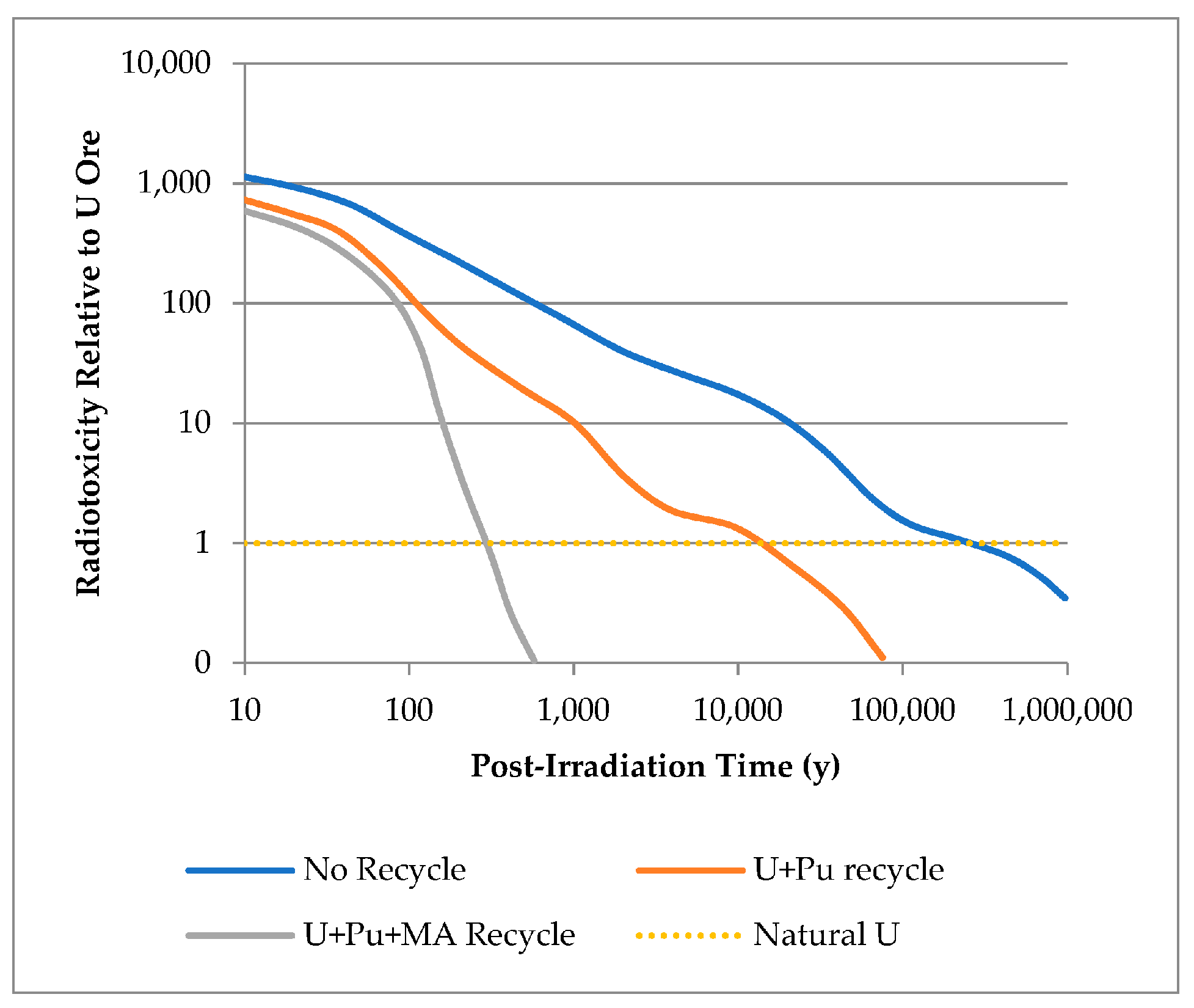
Figure 2.
Simplified schematic summary of the open fuel cycle and the “wait and see” approach.

Figure 3.
Simplified schematic summary of the UREX process with SNF input and primary outputs of this operation.
Figure 3.
Simplified schematic summary of the UREX process with SNF input and primary outputs of this operation.

Figure 4.
Simplified schematic summary of the PUREX process with SNF input and primary outputs of this operation.
Figure 4.
Simplified schematic summary of the PUREX process with SNF input and primary outputs of this operation.
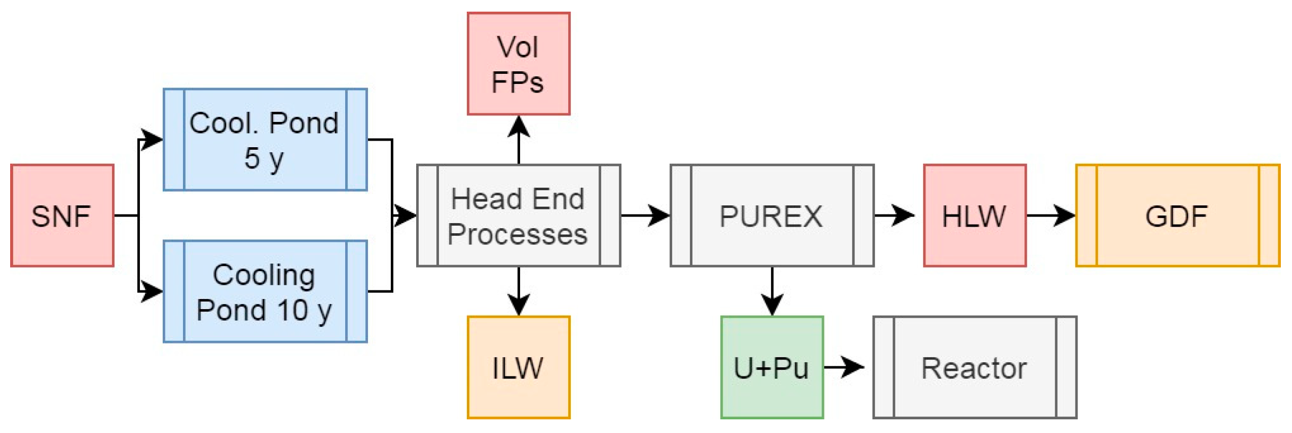
Figure 5.
Simplified schematic summary of the PUREX + SANEX process with SNF input and primary outputs of this operation.
Figure 5.
Simplified schematic summary of the PUREX + SANEX process with SNF input and primary outputs of this operation.
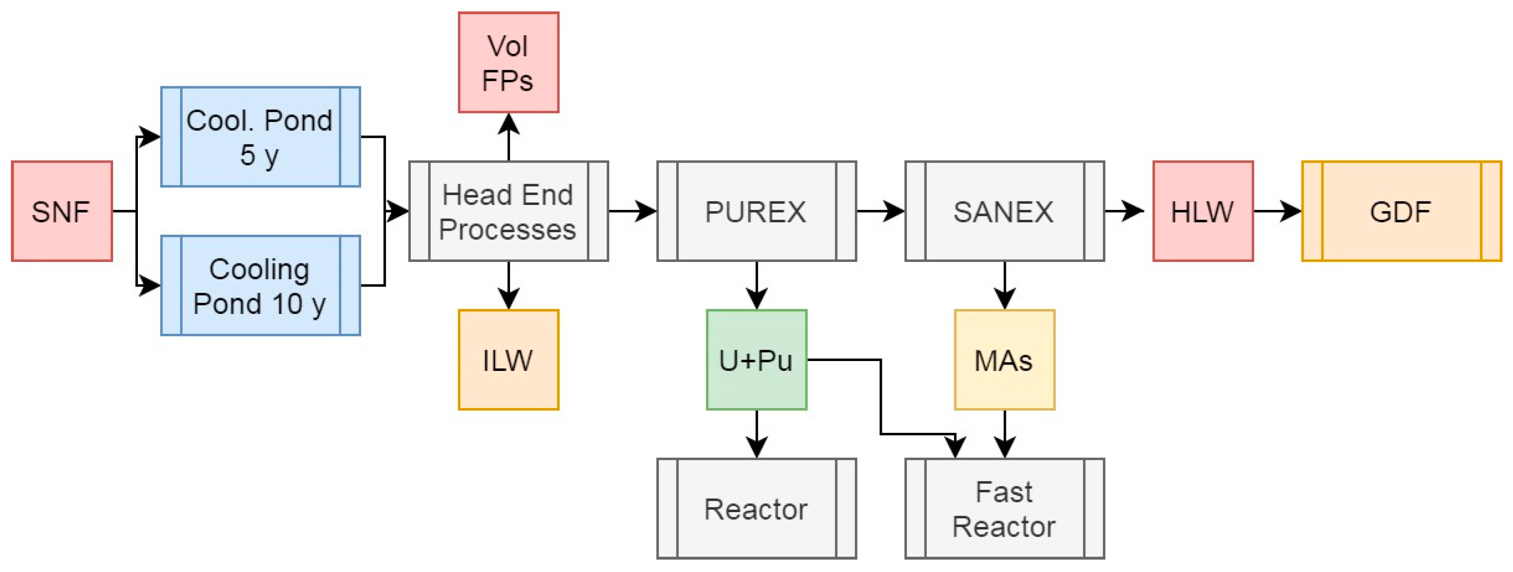
Figure 6.
Simplified schematic summary of the PUREX + SANEX process with SNF input and primary outputs of this operation.
Figure 6.
Simplified schematic summary of the PUREX + SANEX process with SNF input and primary outputs of this operation.
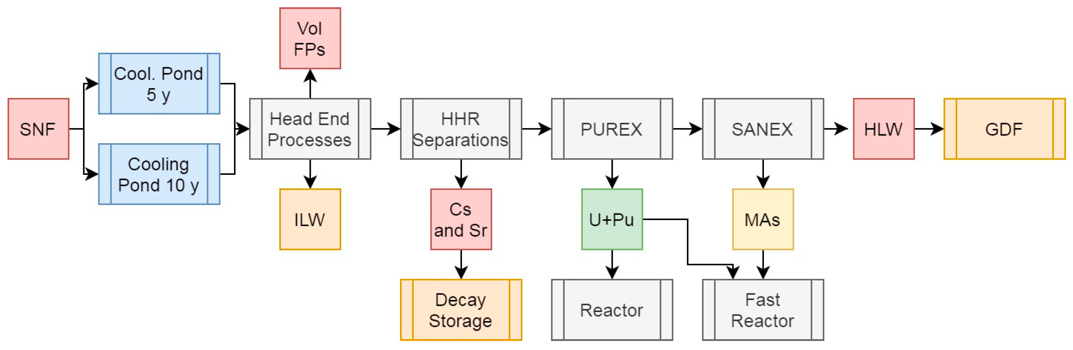
Figure 7.
Simplified schematic summary of the PUREX + SANEX process with SNF input and primary outputs of this operation.
Figure 7.
Simplified schematic summary of the PUREX + SANEX process with SNF input and primary outputs of this operation.
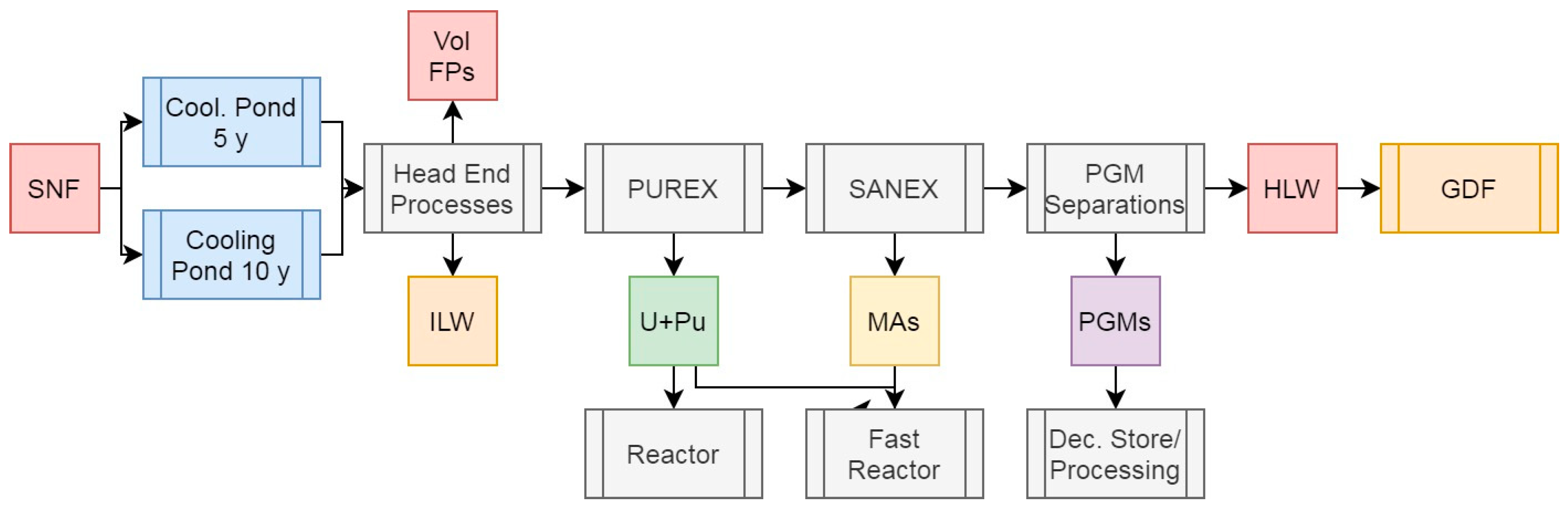
Figure 8.
Simplified schematic summary of the PUREX + SANEX process with SNF input and primary outputs of this operation.
Figure 8.
Simplified schematic summary of the PUREX + SANEX process with SNF input and primary outputs of this operation.
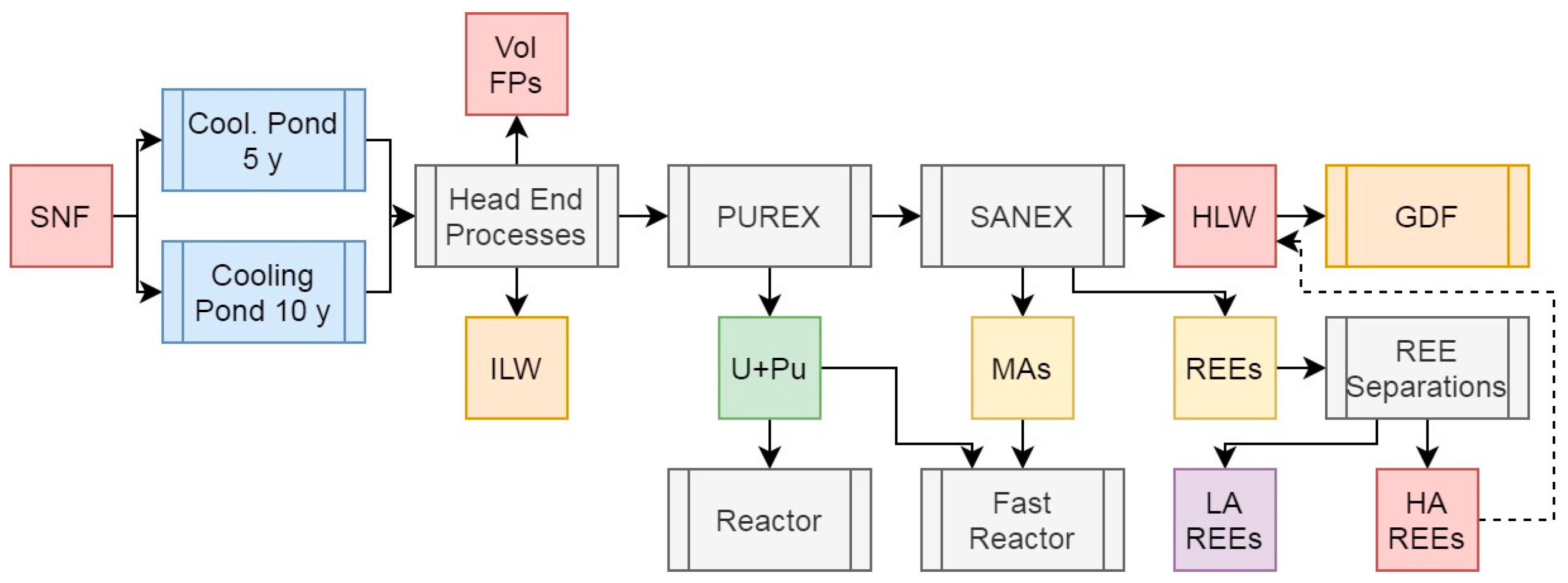
Figure 9.
Graphical summary of HLW masses (a), volumes (b), and decay heats after 5 and 10 years cooling (c) from the SFR scenarios explored in this work. The Scenario 1 values are highlighted in different colours to represent the uncertainty around volume, mass, and decay heats. The values for mass and volume are greater than the scales presented by a significant margin, while the decay heats represent an upper bound depending upon the casks used for disposal.
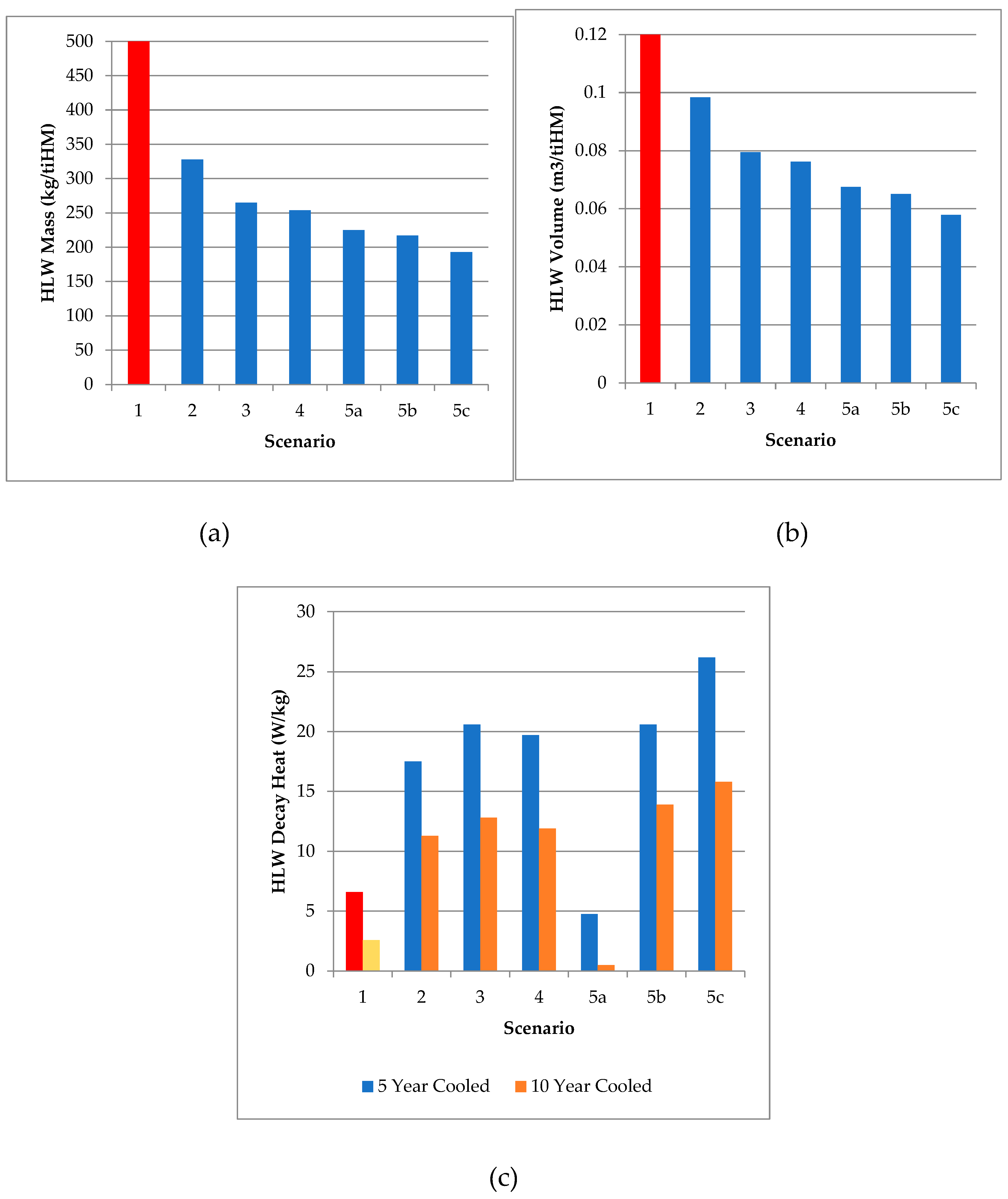
Table 1.
Scenario 2 data including feed masses, activities, decay heats, and specific decay heats. The values for the daughters of U are included with it.
Table 1.
Scenario 2 data including feed masses, activities, decay heats, and specific decay heats. The values for the daughters of U are included with it.
| Masses (g/tiHM) |
Activity (Bq/tiHM) |
Decay Heat (W/tiHM) |
Specif. DH (W/gHM) |
|||||
|---|---|---|---|---|---|---|---|---|
| Feed | 5 y | 10 y | 5 y | 10 y | 5 y | 10 y | 5 y | 10 y |
| U | 9.236E+05 | 9.236E+05 | 3.029E+11 | 2.863E+11 | 1.024E-01 | 1.119E-01 | 1.109E-07 | 1.211E-07 |
| Raffinate | 6.557E+04 | 6.556E+04 | 3.280E+16 | 2.256E+16 | 5.739E+03 | 3.717E+03 | 8.754E-02 | 5.670E-02 |
| Volatile FPs | 1.049E+04 | 1.048E+04 | 4.149E+14 | 3.004E+14 | 4.567E+01 | 3.306E+01 | 4.353E-03 | 3.154E-03 |
| Sum | 9.997E+05 | 9.997E+05 | 3.322E+16 | 2.286E+16 | 5.785E+03 | 3.750E+03 | ||
| U% | 92.39% | 92.39% | 0.00% | 0.00% | 0.00% | 0.00% | ||
| Raffinate% | 6.56% | 6.56% | 98.75% | 98.68% | 99.21% | 99.12% | ||
| Volatile FPs% | 1.05% | 1.05% | 1.25% | 1.31% | 0.79% | 0.88% | ||
Table 2.
Scenario 3 data including feed masses, activities, decay heats, and specific decay heats. The values for the daughters of U are included with it.
Table 2.
Scenario 3 data including feed masses, activities, decay heats, and specific decay heats. The values for the daughters of U are included with it.
| Masses (g/tiHM) |
Activity (Bq/tiHM) |
Decay Heat (W/tiHM) |
Specif. DH (W/gHM) | |||||
|---|---|---|---|---|---|---|---|---|
| Feed | 5 y | 10 y | 5 y | 10 y | 5 y | 10 y | 5 y | 10 y |
| U+Pu | 9.364E+05 | 9.361E+05 | 6.392E+15 | 5.086E+15 | 3.253E+02 | 3.107E+02 | 3.47E-04 | 3.32E-04 |
| Raffinate | 5.280E+04 | 5.313E+04 | 2.641E+16 | 1.747E+16 | 5.414E+03 | 3.407E+03 | 1.03E-01 | 6.41E-02 |
| Volatile FPs | 1.049E+04 | 1.048E+04 | 4.149E+14 | 3.004E+14 | 4.567E+01 | 3.306E+01 | 4.35E-03 | 3.15E-03 |
| Sum | 9.997E+05 | 9.997E+05 | 3.322E+16 | 2.286E+16 | 5.785E+03 | 3.750E+03 | ||
| U% | 93.67% | 93.64% | 19.24% | 22.25% | 5.62% | 8.28% | ||
| Raffinate% | 5.28% | 5.31% | 79.51% | 76.43% | 93.59% | 90.84% | ||
| Volatile FPs% | 1.05% | 1.05% | 1.25% | 1.31% | 0.79% | 0.88% | ||
Table 3.
Scenario 4 data including feed masses, activities, decay heats, and specific decay heats. The values for the daughters of U are included with it.
Table 3.
Scenario 4 data including feed masses, activities, decay heats, and specific decay heats. The values for the daughters of U are included with it.
| Masses (g/tiHM) |
Activity (Bq/tiHM) |
Decay Heat (W/tiHM) |
Specif. DH (W/gHM) | |||||
|---|---|---|---|---|---|---|---|---|
| Feed | 5 y | 10 y | 5 y | 10 y | 5 y | 10 y | 5 y | 10 y |
| U+Pu | 9.364E+05 | 9.361E+05 | 6.392E+15 | 5.086E+15 | 3.253E+02 | 3.107E+02 | 3.47E-04 | 3.32E-04 |
| MAs | 1.836E+03 | 2.157E+03 | 4.128E+14 | 3.939E+14 | 3.855E+02 | 3.660E+02 | 2.10E-01 | 1.70E-01 |
| Raffinate | 5.096E+04 | 5.097E+04 | 2.600E+16 | 1.708E+16 | 5.029E+03 | 3.041E+03 | 9.87E-02 | 5.97E-02 |
| Volatile FPs | 1.049E+04 | 1.048E+04 | 4.149E+14 | 3.004E+14 | 4.567E+01 | 3.306E+01 | 4.35E-03 | 3.15E-03 |
| Sum | 9.997E+05 | 9.997E+05 | 3.322E+16 | 2.286E+16 | 5.785E+03 | 3.750E+03 | ||
| U+Pu% | 93.67% | 93.64% | 19.24% | 22.25% | 5.62% | 8.28% | ||
| MAs% | 0.18% | 0.22% | 1.24% | 1.72% | 6.66% | 9.76% | ||
| Raffinate% | 5.10% | 5.10% | 78.27% | 74.71% | 86.92% | 81.07% | ||
| Volatile FPs% | 1.05% | 1.05% | 1.25% | 1.31% | 0.79% | 0.88% | ||
Table 4.
Scenario 5a data including feed masses, activities, decay heats, and specific decay heats. The values for the daughters of U are included with it.
Table 4.
Scenario 5a data including feed masses, activities, decay heats, and specific decay heats. The values for the daughters of U are included with it.
| Masses (g/tiHM) |
Activity (Bq/tiHM) |
Decay Heat (W/tiHM) | Specif. DH (W/gHM) | |||||
|---|---|---|---|---|---|---|---|---|
| Feed | 5 y | 10 y | 5 y | 10 y | 5 y | 10 y | 5 y | 10 y |
| Cs+Sr | 6.157E+03 | 5.806E+03 | 2.017E+16 | 1.612E+16 | 3.961E+03 | 2.930E+03 | 6.43E-01 | 5.05E-01 |
| U+Pu | 9.364E+05 | 9.361E+05 | 6.392E+15 | 5.086E+15 | 3.253E+02 | 3.107E+02 | 3.47E-04 | 3.32E-04 |
| MAs | 1.836E+03 | 2.157E+03 | 4.128E+14 | 3.939E+14 | 3.855E+02 | 3.660E+02 | 2.10E-01 | 1.70E-01 |
| Raffinate | 4.480E+04 | 4.517E+04 | 5.834E+15 | 9.566E+14 | 1.068E+03 | 1.106E+02 | 2.38E-02 | 2.45E-03 |
| Volatile FPs | 1.049E+04 | 1.048E+04 | 4.149E+14 | 3.004E+14 | 4.567E+01 | 3.306E+01 | 4.35E-03 | 3.15E-03 |
| Sum | 9.997E+05 | 9.997E+05 | 3.322E+16 | 2.286E+16 | 5.785E+03 | 3.750E+03 | ||
| Cs+Sr% | 0.62% | 0.58% | 60.70% | 70.52% | 68.46% | 78.12% | ||
| U+Pu% | 93.67% | 93.64% | 19.24% | 22.25% | 5.62% | 8.28% | ||
| MAs% | 0.18% | 0.22% | 1.24% | 1.72% | 6.66% | 9.76% | ||
| Raffinate% | 4.48% | 4.52% | 17.56% | 4.19% | 18.46% | 2.95% | ||
| Volatile FPs% | 1.05% | 1.05% | 1.25% | 1.31% | 0.79% | 0.88% | ||
Table 5.
Scenario 5b data including feed masses, activities, decay heats, and specific decay heats. The values for the daughters of U are included with it.
Table 5.
Scenario 5b data including feed masses, activities, decay heats, and specific decay heats. The values for the daughters of U are included with it.
| Masses (g/tiHM) |
Activity (Bq/tiHM) |
Decay Heat (W/tiHM) | Specif. DH (W/gHM) | |||||
|---|---|---|---|---|---|---|---|---|
| Feed | 5 y | 10 y | 5 y | 10 y | 5 y | 10 y | 5 y | 10 y |
| U+Pu | 9.364E+05 | 9.361E+05 | 6.392E+15 | 5.086E+15 | 3.253E+02 | 3.107E+02 | 3.47E-04 | 3.32E-04 |
| MAs | 1.836E+03 | 2.157E+03 | 4.128E+14 | 3.939E+14 | 3.855E+02 | 3.660E+02 | 2.10E-01 | 1.70E-01 |
| PGMs | 7.634E+03 | 7.634E+03 | 1.972E+15 | 6.544E+13 | 5.699E+02 | 1.890E+01 | 7.47E-02 | 2.48E-03 |
| Raffinate | 4.333E+04 | 4.334E+04 | 2.403E+16 | 1.701E+16 | 4.459E+03 | 3.022E+03 | 1.03E-01 | 6.97E-02 |
| Volatile FPs | 1.049E+04 | 1.048E+04 | 4.149E+14 | 3.004E+14 | 4.567E+01 | 3.306E+01 | 4.35E-03 | 3.15E-03 |
| Sum | 9.997E+05 | 9.997E+05 | 3.322E+16 | 2.286E+16 | 5.785E+03 | 3.750E+03 | ||
| U+Pu% | 93.67% | 93.64% | 19.24% | 22.25% | 5.62% | 8.28% | ||
| MAs% | 0.18% | 0.22% | 1.24% | 1.72% | 6.66% | 9.76% | ||
| PGMs% | 0.76% | 0.76% | 5.94% | 0.29% | 9.85% | 0.50% | ||
| Raffinate% | 4.33% | 4.34% | 72.33% | 74.42% | 77.07% | 80.57% | ||
| Volatile FPs% | 1.05% | 1.05% | 1.25% | 1.31% | 0.79% | 0.88% | ||
Table 6.
Scenario 5c data including feed masses, activities, decay heats, and specific decay heats. The values for the daughters of U are included with it.
Table 6.
Scenario 5c data including feed masses, activities, decay heats, and specific decay heats. The values for the daughters of U are included with it.
| Masses (g/tiHM) |
Activity (Bq/tiHM) |
Decay Heat (W/tiHM) | Specif. DH (W/gHM) | |||||
|---|---|---|---|---|---|---|---|---|
| Feed | 5 y | 10 y | 5 y | 10 y | 5 y | 10 y | 5 y | 10 y |
| U+Pu | 9.364E+05 | 9.361E+05 | 6.392E+15 | 5.086E+15 | 3.253E+02 | 3.107E+02 | 3.47E-04 | 3.32E-04 |
| MAs | 1.836E+03 | 2.157E+03 | 4.128E+14 | 3.939E+14 | 3.855E+02 | 3.660E+02 | 2.10E-01 | 1.70E-01 |
| REEs (LA) | 1.251E+04 | 1.250E+04 | 1.666E+10 | 3.715E+08 | 1.269E-03 | 1.547E-05 | 1.01E-07 | 1.24E-09 |
| REEs (HA) | 5.041E+03 | 5.059E+03 | 3.731E+15 | 8.519E+14 | 4.824E+02 | 8.717E+01 | 9.57E-02 | 1.72E-02 |
| Raffinate | 3.341E+04 | 3.342E+04 | 2.227E+16 | 1.622E+16 | 4.546E+03 | 2.953E+03 | 1.36E-01 | 8.84E-02 |
| Volatile FPs | 1.049E+04 | 1.048E+04 | 4.149E+14 | 3.004E+14 | 4.567E+01 | 3.306E+01 | 4.35E-03 | 3.15E-03 |
| HA REEs + Raff | 3.845E+04 | 3.848E+04 | 2.600E+16 | 1.708E+16 | 5.029E+03 | 3.041E+03 | 1.31E-01 | 7.90E-02 |
| Sum | 9.997E+05 | 9.997E+05 | 3.322E+16 | 2.286E+16 | 5.785E+03 | 3.750E+03 | ||
| U+Pu% | 93.67% | 93.64% | 19.24% | 22.25% | 5.62% | 8.28% | ||
| MAs% | 0.18% | 0.22% | 1.24% | 1.72% | 6.66% | 9.76% | ||
| REEs (LA)% | 1.25% | 1.25% | 0.00% | 0.00% | 0.00% | 0.00% | ||
| REEs (MA)% | 0.50% | 0.51% | 11.23% | 3.73% | 8.34% | 2.32% | ||
| Raffinate% | 3.34% | 3.34% | 67.04% | 70.98% | 78.59% | 78.75% | ||
| Volatile FPs% | 1.05% | 1.05% | 1.25% | 1.31% | 0.79% | 0.88% | ||
Disclaimer/Publisher’s Note: The statements, opinions and data contained in all publications are solely those of the individual author(s) and contributor(s) and not of MDPI and/or the editor(s). MDPI and/or the editor(s) disclaim responsibility for any injury to people or property resulting from any ideas, methods, instructions or products referred to in the content. |
© 2025 by the authors. Licensee MDPI, Basel, Switzerland. This article is an open access article distributed under the terms and conditions of the Creative Commons Attribution (CC BY) license (http://creativecommons.org/licenses/by/4.0/).
Copyright: This open access article is published under a Creative Commons CC BY 4.0 license, which permit the free download, distribution, and reuse, provided that the author and preprint are cited in any reuse.


