
Submitted:
26 March 2025
Posted:
27 March 2025
You are already at the latest version
Abstract
In this paper, we propose and proof an innovative concept of radar antennas suited for Collision Avoidance (CA) systems installed on board small Unmanned Aircraft (UA). The proposed architecture provides 360º monopulse coverage around the host platform enabling the detection and accurate position estimation of airborne, non-cooperative hazards using lightweight, low-profile antennas. These antennas can be manufactured using low-cost 3D printing techniques and are easily integrable in the UAs airframe without degrading their airworthiness. In the paper, we sketch a Detect and Avoid (DAA) concept of operations (ConOps) built on the ConOps for separation management developed by the SESAR 2020 project BUBBLES in line with the SESAR U-space ConOps Ed. 4. In that ConOps, Remain Well Clear (RWC) and Collision Avoidance functions are provided separately (namely, the responsibility for providing the RWC function lies with ground-based U-space services whereas the CA function is considered an airborne safety net provided by on-board equipment). From the ConOps, we define operation-centric design requirements and describe the proposed architecture. We prove the concept by a combination of simulations and measurements in anechoic chamber using a prototype at 24 GHz.
Keywords:
Collision Avoidance
; monopulse antenna
; sectorial antenna
; cylindrical array
; 3D printed antenna
1. Introduction
Although Unmanned Aircraft Systems (UAS) were long since used in military operations (World War I [1], Vietnam War [2]) it was not until the beginning of the 21st century when the interest in this technology soared in the civil word. Nowadays, there is a huge expectation on a number of potential professional uses of UAS in many fields (urban mobility, delivery, public safety and security, entertainment, agriculture, infrastructure survey, etc.), as well as leisure. Only at European Union (EU) level, there is a projected demand valuated of several billion euro annually in the next decades, leading to the creation of more than 400,000 highly skilled jobs by 2050 [3]. Much of that market corresponds to activities that will take place within what is commonly referred to as Very Low Level (VLL) airspace over densely populated urban areas, as well as industrial ones. The VLL is defined in [4] as the airspace below the specified minimum altitude for flights under Visual Flight Rules (VFR). This does not preclude VFR operations in the VLL, provided they are authorized by the competent authority.
While attracted by their forecasted economical and societal benefits, citizens expect that UAS operations are as safe as manned flights have been over decades and that they have no negative impact on the safety of traditional crewed aviation (see for instance [5]). Therefore, competent authorities worldwide have adopted measures pursuing appropriate levels of safety of UAS operations commensurate with the risk they entail. One example of those measures is the Commission Implementing Regulation (EU) 2019/947 [6] (Reg. 947 hereinafter), which defines three risk-based categories of UAS operations with increasing risk: open, specific, and certified. This regulation is in force in EU Member States since July 2020, as well as in other countries in the European Economic Area (EEA).
Depending on the operational risk, UAS operators may be requested by the competent authorities to implement specific mitigation measures. As a matter of fact, in the EU UAS operators have to conduct a safety assessment using the Specific Operations Risk Assessment (SORA) methodology [7] for those operations which fall in the specific category as per Reg. 947. According to SORA, UAS operators have to assign ground and air risk classes (a.k.a. GRC and ARC, respectively) to the operations in light of the estimated risk [7]. With regard to the air risk, operators have to apply mitigation measures to reduce the risk to acceptable levels unless the operation falls in the lowest risk ARC (namely, ARC-a). As part of these mitigation measures, operators might be requested by the competent authority to use Detect and Avoid (DAA) systems with different levels of performance according to the envisaged risk. Albeit regulations for UAS operating in the certified category are still under development, DAA capabilities have been identified as a pivotal enabler for this type of operations, especially over urban areas [8].
DAA comprises two functions addressing the second and third layers of conflict management (separation provision or Remain Well Clear – RWC – and Collision Avoidance – CA –, respectively) according to [9],[10]. There are currently two parallel threads addressing the specification of DAA systems. On the one hand, the Radiotechnical Commission for Aeronautics (RTCA) has developed a Minimum Operational Performance Standard (MOPS) for Airborne Collision Avoidance System sXu (ACAS sXu) [11], a.k.a. RTCA DO-396. This standard defines the requirements of systems to be installed in a small UA (sUA) with less than 25 ft wingspan1, a.k.a. the ownship, with the purpose of helping remote pilots avoid collisions with a variety of intruders, either manned or unmanned, cooperative or not. On the other hand, the European Organisation for Civil Aviation Equipment (EUROCAE) developed an Operational Services & Environment Description (OSED) for Detect & Avoid in Very Low-level operations (a.k.a. EUROCAE ED-267) [4]. This OSED sets out a system meant to protect ownships operating in the specific category (as per Reg. 947) from intruders compliant with the e-conspicuity requirement as per the Commission Implementing Regulation (EU) 2021/666 [12] (hereinafter Reg. 666). Furthermore, the RTCA Special Committee (SC) 147 is also developing the ACAS Xr concept, addressing the particular features of rotorcraft, including those used for Urban Air Mobility (UAM) and Advanced Air Mobility (AAM) operations [13].The system set out in DO-396 does not provide separate RWC and CA functions but a single layer of warning alerts and directive guidance instead, using protection volumes based on the intruder type. Conversely, ED-267 accounts for two separate functions, with the RWC one being provided by either on board or ground-based systems and the CA by on board equipment.
On the other hand, the concept of UA Systems (UAS) Traffic Management (UTM) arose in the mid 2010s as a ‘a specific aspect of air traffic management which manages UAS operations safely, economically, and efficiently through the provision of facilities and a seamless set of services in collaboration with all parties and involving airborne and ground-based functions’, according to the International Civil Aviation Organisation (ICAO) definition in [14]. Based on the ICAO’s UTM framework several ConOps for the provision of UTM services have been developed worldwide (e.g., [15],[16]). The regional implementation of the UTM concept in the EU is known as U-space and it is being developed (by appointment of the European Commission) by the Single European Sky Air Traffic Management Research (SESAR) Joint Undertaking (JU) through the research projects CORUS and CORUS-XUAM, leading to the publication of the latest version of the U-space ConOps in 2023 [17].
Based on the U-space ConOps, the European Commission has set up a comprehensive regulatory framework requesting UAS operators to use some of the so-called U1 (foundation) U-space services [18] (e-registration and e-identification) plus an airborne geo-awareness function (requested by the Commission Delegated Regulation (EU) 2019/945 [19] amended by [20], jointly referred to as Reg. 945 hereinafter). Furthermore, Commission Implementing Regulation (EU) 2021/664 (Reg. 664 hereinafter) introduces the concept of U-space airspace as a UAS geographical zone (in the sense of Art. 15 of Reg. 947) [21] where UAS operations can only take place with the support of a number of U1 and U2 (initial) U-space services (at least, network identification, flight authorisation, geo-awareness and traffic information) plus some common information services that can be provided by a federation of entities or by a single designated organisation (at the discretion of Member States). This regulation applies to all UAS operation categories defined in Reg. 947 with the only exceptions of the lowest-risk open category operations and operations conducted under Instrumental Flight Rules (IFR). With regards to manned aviation, aircraft receiving air traffic control instructions will be dynamically segregated from UAS by means of a Dynamic Airspace Reconfiguration mechanism set out in [22], [23]. Aircraft flying without receiving air traffic control instructions can fly in U-space provided that they comply with the e-conspicuity requirement as per Reg. 666. The traffic information service provides UAS operators with a comprehensive picture of the traffic around those aircraft (UA) which are under their control. The ultimate responsibility for avoiding any collision hazard lies with UAS operators based on the information provided by the traffic information service. However, SESAR envisages that in the mid-term, as the demand increases, a U3 (advanced) Tactical Conflict Resolution (TCR) service will be put in place to enable denser UAS operations by providing tactical separation [25]. Indeed, SESAR is currently funding some research projects, such as SPATIO [25], aimed at delivering some solutions for tactical conflict resolution at a rather high maturity level by 2026. In line with that approach and in the light of the DAA system described in ED-267, in this paper we assume that the RWC function is provided by the U-space tactical conflict resolution service whereas the CA function relies on airborne systems.
Both DO-396 and ED-267 recognise Air-to-Air RADAR (ATAR) as one of the crucial technologies enabling DAA. The reference standard for DAA ATAR is RTCA DO-366, MOPS for Air-to-Air Radar for Traffic Surveillance [26]. However, DO-396 points out that DO-366 compliant ATARs might have size, weight, and power (SWAP) requirements non compatible with small drones. Along with SWAP issues, there is another relevant difference between DO-396 ATAR and those for larger UAS DAA systems such as ACAS Xu specified in EUROCAE ED-275 [27]: the radar field of vision (FOV) is widened from a typical value of with respect to the longitudinal axis of the UAS to cover the full range of around the aircraft. Of course, cost is another driving factor: an ACAS Xu compliant with ED-275 costs by far more than a typical multirotor UAS or a small fixed-wing one.
Considering that antennas are major contributors to radars’ size, weight, and cost, the design of cheap, lightweight antennas with low aerodynamic profile covering the full range of around a host aircraft arises as a clear research need to enable regular UAS operations using CA systems. Several research papers describing antennae architectures for UAS detecting radars have been published in recent years (see for instance [28]-[33]). However, none of them fulfils all the SWAP and FOV requirements defined in DO-396 for sXu ATARs.
In this paper, we propose and prove an innovative concept of antenna architecture addressing the research need stated above. The proposed architecture consists of a circular array of sectorial cavity antennas that generates overlapped fixed radiation patterns shifted by radians around the hosting aircraft. Each pair of adjacent sectors synthesises a monopulse radiation pattern [34] pointing to a predefined direction (namely, the sector boresight). We compute the off-boresight angle of a target (a.k.a. threat) by processing the sigma and delta channels of the monopulse patterns as it is done in state-of-the-art mode S radars [35]. Then, we use the phase of the delta channel to determine the sign to be applied to the off-boresight angle. In this way, we can accurately estimate the angular position of a threat in a angular range around the ownship using compact radiating structures easily integrable into the UAS airframe. We have proved the proposed concept by means of a combination of simulations and experimental techniques.
The rest of the paper is organized as follows: in Section 2 we derive the design requirements of the antenna based on the intended operation. In Section 3 we formulate the proposed antenna architecture concept addressing the requirements derived in Section 2, supported by numerical analysis. In section 4 we describe the approach that we have used to prove the concept formulated in Section 3 and present the experimental results we got using a prototype. Section 5 we discuss the results provided in Section 4 to demonstrate the level of technological maturity achieved by the proposed concept, summarise the conclusions of the work and outline the way forward towards higher maturity levels.
2. Design Requirements
In this section we derive design requirements for a CA radar antenna from the system operational requirements, based on ATAR specifications in DO-366. Antennas are a crucial component of any radar system, since they affect detection range and angular accuracy. According to the assumption stated in Section 1, the CA function tiggers when the U-space tactical conflict resolution service fails, and the intruder breaches the RWC protection volume (a.k.a. loss of well clear -LoWC – or separation loss). Then, the purpose of the CA function is to keep the intruder out the Near Mid-Air Collision (NMAC) volume. In case the intruder penetrates the NMAC, providence would remain as the last chance barrier before an accident (i.e., a mid-air collision – MAC) occurs.
Both RTCA and EUROCAE approaches use a 2,000 ft radius, 500 ft height cylinder centred at the ownship as protection volume for RWC and a 500 ft radius, 200 ft height cylinder as Near Mid-Air Collision (NMAC) volume for CA purposes as regards larger intruders (General Aviation – GA – or UAM/AAM aircraft), as proposed in [36]. Furthermore, DO-396 also proposes a small UA NMAC (sNMAC) consisting of a 50 ft radius, 30 ft height cylinder centred at the ownship, according to [37]. Based on that sNMAC ,DO-396 proposes a cylindrical RWC volume with 200 ft radius and 50 ft height for sUA. Therefore, the CA radar detection range shall be 2,000 ft (i.e., 619 m) for GA and UAM/AAM intruders and 200 ft (61 m) for sUA.
DO-366 lists the frequency bands where ATAR radar shall operate, which lie with C, X, Ka, K and Ku bands. In this paper, we use the 24 GHz Industrial, Medical and Scientific (ISM) band, which is very close to the DO-366 K band (24.45 GHz – 24.65 GHz). The rationale for this choice is that the small wavelength in this band (around 12.5 mm) enables the design of compact, lightweight antennas that can be fitted into sUAS without affecting their airworthiness. Moreover, there are a good number of Commercial-Off-The-Shelf (COTS) components that would enable low-cost implementations of the radar system. As a matter of fact, the wide-band solid-state power amplifier RFLUPA18G26GF delivers 54 dBm (typical) in the band from 18 GHz to 26.5 GHz [38]. For the receiving chain, there is, for instance, the ADF5904 receiver downconverter with a noise figure of 10 dB at 24 GHz [39]. The main drawback of this frequency is the high free-space losses, but because of the relatively short detection range they do not affect the feasibility of a radar implementation in this band, as we demonstrate at the end of this section.
With regards to the radar cross section () of the intruder, Annex E to DO-366 [11] provides a figure of 5 dBsm for GA aircraft at 13 GHz, based on numerical analyses. Given that, also according to [11], the radar cross section remains almost constant from X to Ku band, we assume that this kind of targets are in the optical region at those frequencies (i.e., is given by the area subtended by the target at the radar location and does not depend on the frequency [40]) and we use the same value in K band. We also use that value for UAM/AAM aircraft because of the apparent similarities of those vehicles with GA rotorcraft. For sUA, [41] presents the results of a thorough experimental assessment of a variety of sUA radar cross section. From the results presented in that paper, we assume a radar cross section for sUAS of -16 dBsm at 24 GHz.
We assume that the radar will be a continuous wave, linearly frequency modulated (CW-LFM) radar. Furthermore, we assume that the period of the modulating signal () is adjusted so that the detection range is unambiguous (i.e., [42]).
Based on those assumptions, we used the CW-LFM radar equation from [42] to estimate the required antenna gain (considering that the transmitting and the receiving antennas are identical):
where is the Boltzmann’s constant and
We assume (i.e., 99% probability of detection and probability of false alarm with a matched receiver) [43] and , being [26]. is the time needed to detect targets within a range bin by means of a Fast Fourier Transform (FFT) and digital filtering processing of the received signal. Assuming 8 range bins and a Hamming windowing, we get
Finally, from the assessments in Annex B of DO-396, we assume that nominal FOV on the antenna shall be 360 in azimuth, whereas the coverage in elevation shall be as large as possible.
3. Formulation of a Concept of Radar Antennas for CA Systems
In this section we formulate a concept of radar antennas aimed at being used in CA systems onboard sUA according to the requirements set out in Section 2. First, in Section 3.1, we propose a candidate architecture based on expert judgement. Then, in Section 3.2 we elaborate on that candidate architecture by means of numerical analysis supported by a state-of-the-art full-wave electromagnetic simulation tool.
3.1. Identification of a Candidate Architecture
Typical radar antennas providing 360 azimuthal coverage are rotating antennas with narrow beams in azimuth and vertical radiation patterns made of stacked or electronically steered beams [44]. Since those antennas are usually apertures pointing towards the horizon and rotating around the z axis, the vertical radiation pattern never covers the full , producing what is commonly known as ‘cone of silence’ [45]. Modern radars also use fixed antennas where beams are electronically steered or switched to cover the specified volume [44]. This can be accomplished by means of circular arrays or by one or several rectangular arrays properly laid out. A third architecture, the so-called ‘ubiquitous radar’ was recently proposed and tested [46],[47]. In a ubiquitous radar, energy is transmitted through an omnidirectional pattern and echoes are received through a number of digitally beamformed patters and processed in parallel.
Considering the particularities of the intended host platform, we preferred the option of circular array rather than a rotating antenna because it seems better suited to provide 360 coverage around the platform. Moreover, this architecture enables either electronically steered, switched or ubiquitous implementations.
On the other hand, in order to achieve a fair angular accuracy, we have opted for a 3D monopulse implementation. This architecture, widely used in aviation surveillance to improve the angular accuracy of secondary surveillance radars [36], is based on the combination of the signals received through four independent antennas arranged as shown on the leftmost side of Figure 1 to generate one sigma () and two delta channels ( and ), which are used to compute off-boresight angles in azimuth and elevation and thus provide the angular position of the target. The accuracy of the angular position is driven by depth of the null of the sigma diagrams: the deeper the null, the more accurate the angular measurement. The rightmost side of Figure 1 describes how the , and channels are built from the signals received from each of the four antennas, whereas the channel is also used for transmission.
Azimuth and elevation off-boresight angles ( and , respectively) are computed by comparing the phase of the corresponding channel with that of the channel [36]:
whereas the corresponding boresight angles ( and , respectively) are obtained from the antenna set up. Therefore, targets’ angular position is computed as:
3.2. Design of a Prototype Implementing the Candidate Architecture
For the sake of simplicity and ease of manufacture, we opted for an implementation consisting of a circular array of sectorial apertures. Starting from a baseline model in CST studio®, a well-known, state-of-the-art full wave electromagnetic simulator [48], we made use of CST optimisation capabilities to get the final shown in Figure 2. That model was built using a material with the same conductivity as the material used in the prototype for the experimental proof of concept set out in Section 4 (AlSi10Mg).
The final design consists of a circular array of two rows of eight sector waveguide apertures fed through 50 Ω coaxial lines. The diameter of the circular plates is 90 mm and the distance between them is 10 mm. We added 10 mm height flanges were on the upper and lower plates to improve the isolation between feeding ports. The width of all the elements is 1.5 mm because of the manufacturing method selected to build the prototype (refer to section 4 for details). The central 15 mm diameter metallic post was added for the sake of mechanic robustness and the feeding points are located on the sectors’ symmetry plane, 21 mm away from the centre of the circular plates. This value was established after an optimisation process aimed at getting return losses below 10 dB and isolation between adjacent feeding points greater than 40 dB. Those values are not defined in existing standards, thus we set them as design goals based on of our experience in the field.
This structure produces eight monopulse patterns, with , with (providing full 360 coverage) and rad. Each monopulse pattern is obtained by feeding clusters of four adjacent sectors, as depicted in Figure 3. According to the monopulse architecture illustrated in Figure 1, we obtain the channel by adding in phase the four sectors (i.e., I + II + III + IV), the channel by adding in phase the signals received through sectors I and IV and those received through sectors II and III with opposite phase (I + IV – II – III) and the by adding in phase the signals received through sectors I and II and those received through sectors III and IV with opposite phase (i.e, I + II – III – IV).
Figure 4 depicts the scattering parameters of the antenna in Figure 2 that we obtained using CST with the ports labelled as defined in Figure 3, showing that both the return losses and isolation are well below the design goals at the radar operating frequency (24 GHz). That figure shows that we met the design criteria, leaving a good margin accounting for manufacturing effects.
Figure 5 and Figure 6 show the radiation patterns and on the horizontal plane () that we obtained by simulation for the boresight angle whereas Figure 7 and Figure 8 illustrate the radiation patterns and that we obtained on the vertical plane for the same boresight angle. The pattern in Figure 5 presents a ripple of dB, usual in this type of electrically large antennas (more than 5.5 in the horizontal plane for a given boresight angle). However, that size is needed to get the targeted gain. A similar behaviour has been reported in the literature (see, for instance [33]).
According to those results, we get a gain of 12.6 dBi in the radiation pattern with -3dB beamwidths of on the horizontal plane and on the vertical plane. With regards to the difference diagrams, the most representative parameter is the depth of the null, which is 58 dB for in the pattern and 26 dB for the .
4. Experimental Proof of Concept
4.1. Material and Methods
In order to experimentally prove our concept of radar antenna, we used the CST model in Figure 2 to build a solid model that of the antenna that was manufactured by PCBWay [49] in aluminium (AlSi10Mg) using the Selective Laser Melting (SLM) technology. The resulting prototype is depicted in Figure 16, which weights 163 g.
We measured the protype shown in Figure 10 in the anechoic chamber at the Antennas and Propagation Lab (APL) on the Universitat Politècnica de València (UPV) campus. The measurement space within the chamber is 3 meters long, 2 m wide and 2 m high and it is fitted with a spherical measurement system that allows the measurement of antenna scattering parameters and radiation patterns up to 50 GHz.
In the light of the antenna symmetry, we only measured the radiation pattern for one boresight angle. Using the experimental set up depicted in Figure 11 we measured the scattering parameters between the ports defined in Figure 3 and the horizontal and vertical cuts of the radiation pattern, as well as the antenna gain. We present those results in Section 4.2 below.
4.2. Results
We present the scattering parameters that we measured in the lab in Figure 12. Although the return losses (S11) are higher than the figure that we obtained by simulation (15.33 dB), that value still fulfils the design requirement specified in Section 2 (10 dB). The isolation between ports in Figure 12 is also poorer than in the simulated results, but still acceptable considering the requirements (40 dB minimum).
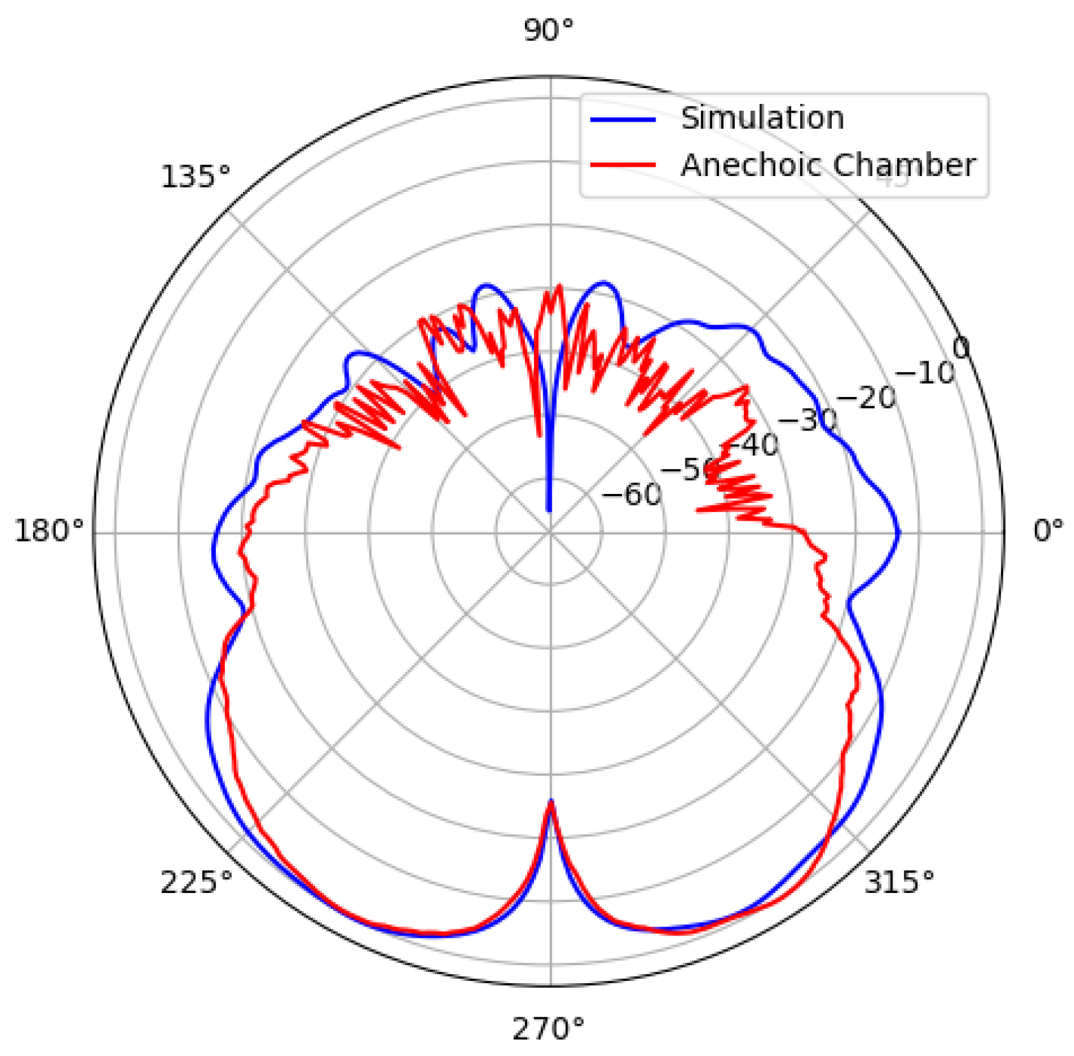
We illustrate in Figure 13 and Figure 14 the comparison between the and radiation patterns measured (plotted in red) and simulated (plotted in blue) on the horizontal plane, whereas the corresponding results for the and on the vertical plane are presented in Figure 15 and Figure 16.
Figures 13 to 16 show a notable agreement between the measured and simulated patterns, with small differences in the side and back lobes attributable to the effect of the mast used to fix the prototype for the measurements and the in the depth of the null in the pattern due to the sensitivity of the measurement. Lastly, we measured a gain of 11.8 dBi, whose difference with the design target (13 dBi) can be easily compensated by means of radar processing techniques not accounted for in Eq. 1, such as signal integration.
5. Discussion and Conclusions
In this paper we have introduced and proved a concept of monopulse antenna suited for Collision Avoidance systems meant to prevent collisions between UAs with a maximum dimension of less than 25 ft (typically used in UAS operations in the specific category according to the European regulation) whereas the Remain Well Clear function is entrusted to ground-based U-space/UTM services. Such antenna enables the detection of large intruders (GA and UAM/AAM aircraft) at around 2,000 ft from the ownship and sUA at around 200 ft using CW-LFM radars implemented with COTS components. We used a well-known full-wave electromagnetic simulator (CST) to design a prototype, which was printed using SLM 3D printing technology with AlSi10Mg. The prototype has a low aerodynamic profile that will not degrade ownship's airworthiness, weighs 163 g and costed around 200 euro on a per-unit basis. We measured the performance of the antenna in an anechoic chamber and found that it closely matches the simulated design and meets the design requirements. The results presented in this paper prove that the concept that we present in this paper currently has a technology readiness level (TRL) 3 according to the scale used in the European R&D framework programs [50] (i.e., experimental proof of concept), and it is a strong candidate for developing radar antennas for CA systems intended for sUA. However, further research is needed to assess the effect of the radome and explore possible implementations using other technologies, such as groove waveguides, which could lead to lighter antennas with even less aerodynamic load.
Author Contributions
Conceptualization, J. V. Balbastre.; methodology, M. Ferrando and J. Ruiz; validation, J. Ruiz; formal analysis, M. Ferrando.; resources, J. Balbastre.; writing—original draft preparation, J. Ruiz; writing—review and editing, J. Balbastre and M. Ferrando; supervision, M. Ferrando and J. Balbastre. All authors have read and agreed to the published version of the manuscript.
Funding
This research was conducted within the framework of CREATE U-space project. CREATE U-space project (CIAICO/2022/044) has received funding from the Conselleria de Innovación, Universidades, Ciencia y Sociedad Digital of the Generalitat Valenciana.
Acknowledgments
We kindly appreciate the support of Mr Bernardo Bernardo from UPV’s APL in conducting the experimental characterisation of the prototype
Conflicts of Interest
The authors declare no conflicts of interest.
Abbreviations
The following abbreviations are used in this manuscript:
| AAM | Advanced Air Mobility |
| ACAS | Airborne Collision Avoidance System |
| APL | Antennas and Propagation Lab |
| ARC | Air Risk Class |
| ATAR | Air-to-Air RADAR |
| CA | Collision Avoidance |
| ConOps | Concept of Operation |
| COTS | Commercial-Off-The-Shelf |
| CW-LFM | Continuous Wave, Linearly Frequency Modulated, |
| DAA | Detect and Avoid |
| EEA | European Economic Area |
| EU | European Union |
| EUROCAE | European Organisation for Civil Aviation Equipment |
| FFT | Fast Fourier Transform |
| FOV | Field of Vision |
| GA | General Aviation |
| GRC | Ground Risk Class |
| ICAO | International Civil Aviation Organisation |
| IFR | Instrumental Flight Rules |
| ISM | Industrial, Medical and Scientific |
| MAC | Mid-air collision |
| MOPS | Minimum Operational Performance Standard |
| NMAC | Near Mid-Air Collision |
| OSED | Operational Services and Environment Description |
| RCS | Radar Cross Section |
| RTCA | Radiotechnical Commission for Aeronautics |
| RWC | Remain Well Clear |
| SC | Special Committee |
| SESAR | Single European Sky Air Traffic Management Research |
| SLM | Selective Laser Melting |
| sNMAC | small UAS NMAC |
| SORA | Specific Operations Risk Assessment |
| sUA | Small UA |
| SWAP | Size, Weight, and Power |
| TCR | Tactical Conflict Resolution |
| TRL | Technology Readiness Level |
| VFR | Visual Flight Rules |
| VLL | Very Low Level |
| UA | Unmanned Aircraft |
| UAM | Urban Air Mobility |
| UAS | Unmanned Aircraft System |
| UTM | Unmanned Aircraft System Traffic Management |
| 1 | Notice that this definition comes from the DO-396 and should not be confused with other similar weight-based definitions commonly used in the literature (such as the small UAS with a maximum take-off weight below 55 pounds). |
References
- Imperial War Museums. Available online: https://www.iwm.org.uk/history/a-brief-history-of-drones (accessed on 17th March 2025).
- Wagner, William, “Lightning Bugs, and other Reconnaissance Drones”, 1982, published by Armed Forces Journal International in cooperation with Aero Publishers, Inc.
- European Drones Outlook Study, SESAR JU, Nov. 2016.
- ED-267 Operational Services & Environment Description (OSED) for Detect & Avoid in Very Low-level operations, European Organisation for Civil Aviation Equipment (EUROCAE).
- Study on the societal acceptance of Urban Air Mobility in Europe, European Union Aviation Safety Agency (EASA), 2021.
- Commission Implementing Regulation (EU) 2019/947 of 24 May 2019 on the rules and procedures for the operation of unmanned aircraft.
- Easy Access Rules for Unmanned Aircraft Systems, European Union Aviation Safety Agency (EASA), July 2024.
- EASA concept for regulation of Unmanned Aircraft Systems (UAS) operations in the ‘certified’ category and Urban Air Mobility - Issue 3.0, European Union Aviation Safety Agency (EASA), 2021.
- Concept of Use for the Airborne Collision Avoidance System Xu for Smaller UAS (ACAS sXu), Federal Aviation Administration (FAA), Version 2, 2020.
- Global Air Traffic Management Operational Concept, International Civil Aviation Organisation (ICAO), 1st Edition, 2005.
- DO-396 Minimum Operational Performance Standards for Airborne Collision Avoidance System sXu (ACAS sXu), Radiotechnical Commission for Aeronautics (RTCA).
- Commission Implementing Regulation (EU) 2021/666 of 22 April 2021 amending Regulation (EU) No 923/2012 as regards requirements for manned aviation operating in U-space airspace.
- RTCA Paper No. 261-22/PMC-2336, available at https://www.rtca.org/wp-content/uploads/2024/07/SC-147-TOR-Rev-20-Approved-2022-09-15-1.pdf (retrieved on March 17th 2025). Radiotechnical Commission for Aeronautics (RTCA).
- Unmanned Aircraft Systems Traffic Management (UTM) – A Common Framework with Core Principles for Global Harmonization, the International Civil Aviation Organisation, Ed. 4, 2023.
- UTM Concept of Operations, v2.0, Federal Aviation Administration, v2.0, 2020.
- RPAS Traffic Management (RTM) System: Concept of Operations Version 1.1, NavCanada 2023.
- U-space ConOps and architecture, Ed. 4.0, CORUS-XUAM project, 2023.
- European ATM Master Plan, Edition 2020, SESAR Joint Undertaking.
- Commission Delegated Regulation (EU) 2019/945 of 12 March 2019 on unmanned aircraft systems and on third-country operators of unmanned aircraft systems.
- Commission Delegated Regulation (EU) 2020/1058 of 27 April 2020 amending Delegated Regulation (EU) 2019/945 as regards the introduction of two new unmanned aircraft systems classes.
- Commission Implementing Regulation (EU) 2021/664 of 22 April 2021 on a regulatory framework for the U-space.
- Commission Implementing Regulation (EU) 2021/665 of 22 April 2021amending Implementing Regulation (EU) 2017/373 as regards requirements for providers of air traffic management/air navigation services and other air traffic management network functions in the U-space airspace designated in controlled airspace.
- Easy Access Rules for U-space, European Union Aviation Safety Agency (EASA), May 2024.
- European ATM Master Plan, Edition 2025, SESAR Joint Undertaking.
- SPATIO website https://research.dblue.it/spatio/ (retrieved on March 17th, 2025).
- DO-366 Minimum Operational Performance Standards for Air-to-Air Radar for Traffic.
- Surveillance, Radiotechnical Commission for Aeronautics (RTCA), 2020.
- EUROCAE ED-275 - Minimum Operational Performance Standard (MOPS) for ACAS Xu, European Organisation for Civil Aviation Equipment (EUROCAE).
- Moses, M. J. Rutherford and K. P. Valavanis, "Radar-based detection and identification for miniature air vehicles," 2011 IEEE International Conference on Control Applications (CCA), Denver, CO, USA, 2011, pp. [CrossRef]
- N. Iwakiri, N. Hashimoto, T. Kobayashi, "Performance Analysis of Ultra-Wideband Channel for Short-Range Monopulse Radar at Ka-Band", Journal of Electrical and Computer Engineering, vol. 2012, Article ID 710752, 9 pages, 2012. [CrossRef]
- G. Fasano, D. Accado, A. Moccia and D. Moroney, "Sense and avoid for unmanned aircraft systems," in IEEE Aerospace and Electronic Systems Magazine, vol. 31, no. 11, pp. 82-110, November 2016. [CrossRef]
- M. Hägelen, R. Jetten, R. Kulke, C. Ben and M. Krüger, "Monopulse Radar for Obstacle Detection and Autonomous Flight for Sea Rescue UAVs," 2018 19th International Radar Symposium (IRS), Bonn, Germany, 2018, pp. 1-7. [CrossRef]
- Á. D. de Quevedo, F. I. Urzaiz, J. G. Menoyo and A. A. López, "Drone Detection With X-Band Ubiquitous Radar," 2018 19th International Radar Symposium (IRS), Bonn, Germany, 2018, pp. 1-10. [CrossRef]
- Haider Al and David Johnson, A Modular Conformal Antenna Array for Wide-Beam SAR and DAA Radars, 2023 IEE International Radar Conference. [CrossRef]
- Zhen Wang, A. Sinha, P. Willett and Y. Bar-Shalom, "Angle estimation for two unresolved targets with monopulse radar," in IEEE Transactions on Aerospace and Electronic Systems, vol. 40, no. 3, pp. 998-1019, July 2004. [CrossRef]
- Doc. 9924 Aeronautical Surveillance Manual, International Civil Aviation Organisation (ICAO), 3rd Edition, 2020.
- F3442/F3442M-20 Standard Specification for Detect and Avoid System Performance Requirement, the American Society for Test and Materials (ASTM), May 1st, 2020.
- Weinert, A., Alvarez, L. Owen, M., and Zintak, B., Near Mid-Air Collision Analog for Drone Based on Unmitigated Collision Risk, AIAA Journal of Air Transport, 2022.
- https://www.rflambda.com/pdf/poweramplifier/RFLUPA18G26GF.pdf, retrieved on March 17th, 2025.
- https://www.analog.com/en/products/adf5904.html, retrieved on March 17th, 2025.
- V. Semkin et al, IEE Access, Vol. 8, pp. 48958-48969, 2020.
- R. Mahafza, Radar Systems Analysis and Desing using Matlab, Chapman and Hall, 2020.
- Merryl, I. Skolnik, Introduction to Radar Systems, MC Graw-Hill, 3rd Edition, 2000.
- Merryl, I. Skolnik (editor), Radar Handbook, Mc Graw-Hill, 3rd Edition, 2008.
- H. Meikle, Modern Radars, Artech House, 2nd Edition, 2008.
- M. Skolnic, Systems Aspects of Digital Beamforming Ubiquitous Radars, Naval Research Laboratory, 2002.
- Á. D. de Quevedo, F. I. Urzaiz, J. G. Menoyo and A. A. López, "Drone Detection With X-Band Ubiquitous Radar," 2018 19th International Radar Symposium (IRS), Bonn, Germany, 2018, pp. 1-10. [CrossRef]
- https://www.3ds.com/es/products/simulia/cst-studio-suite, retrieved on March 17th, 2025.
- https://www.pcbway.com, retrieved on March 17th, 2025.
- https://ec.europa.eu/research/participants/data/ref/h2020/other/wp/2018-2020/annexes/h2020-wp1820-annex-g-trl_en.pdf, retrieved on March 18th, 2025.
Figure 1.
Operational diagram of a monopulse antenna.
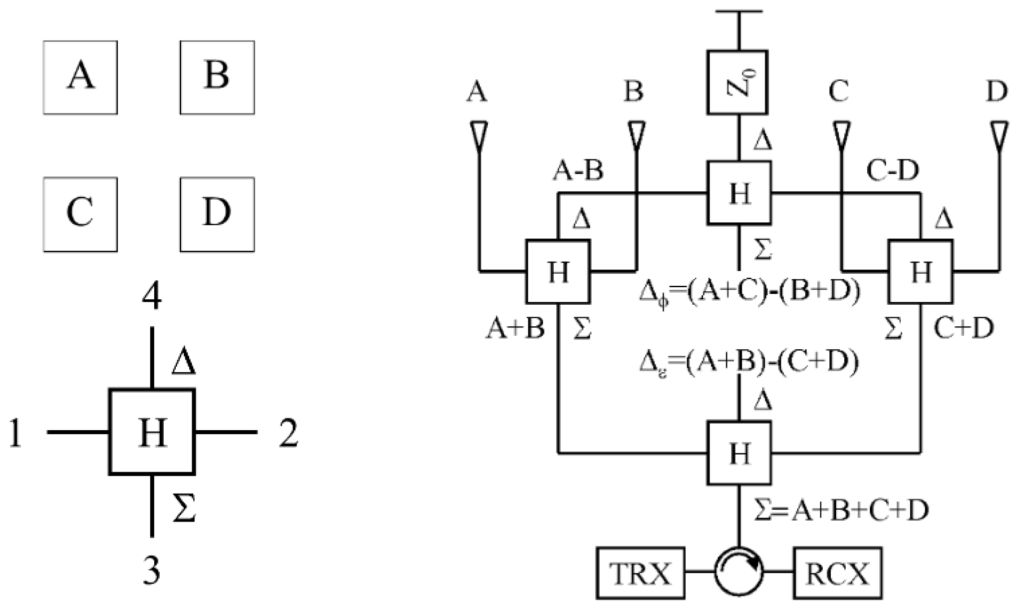
Figure 2.
Final model of the radar antenna in CST.
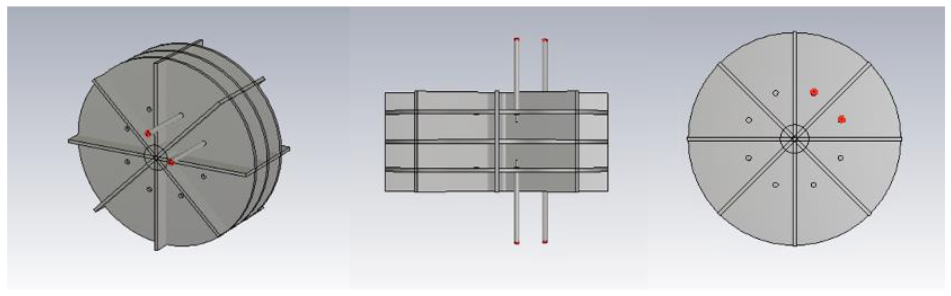
Figure 3.
Representative view of the cavities that are excited.
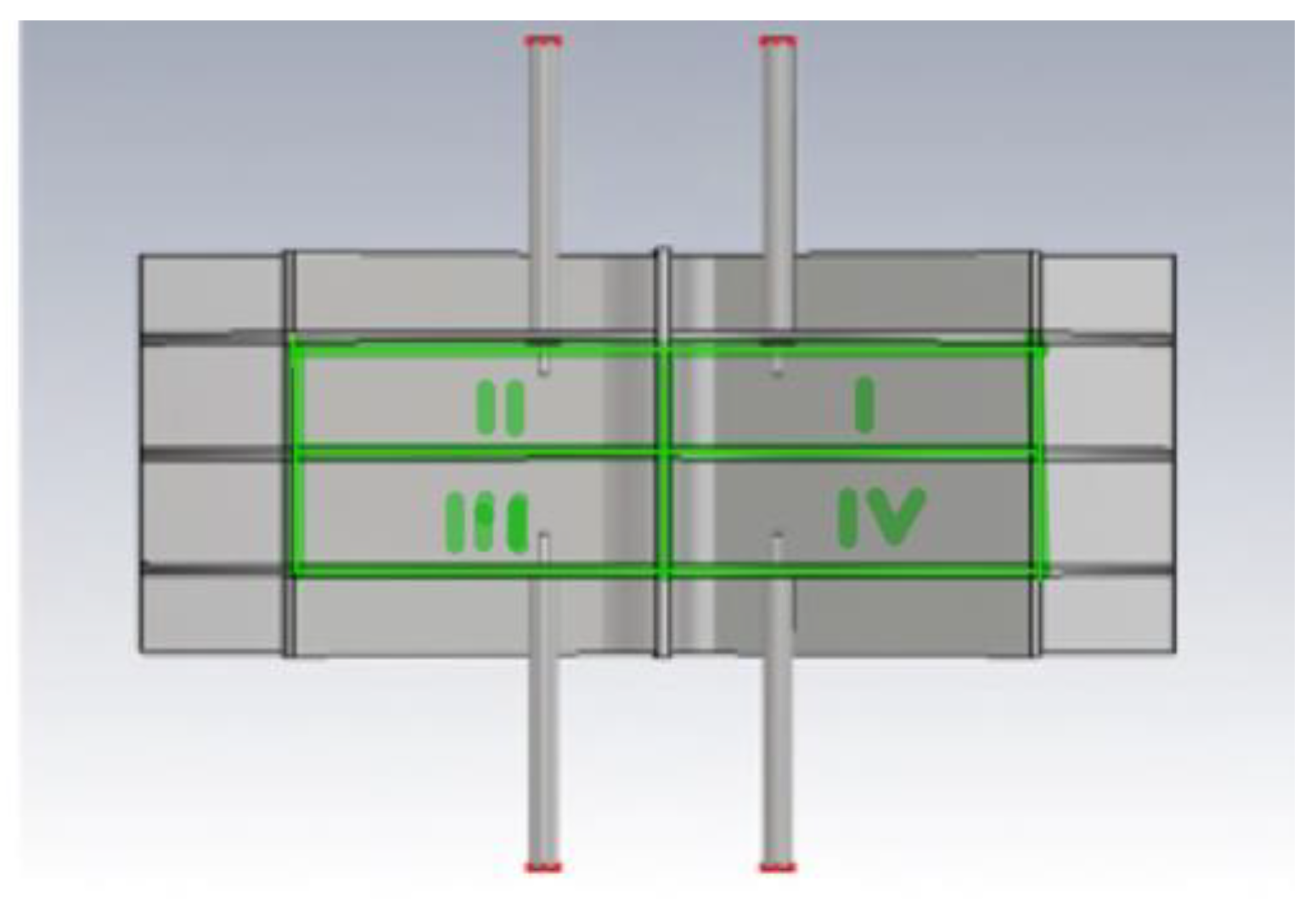
Figure 4.
CST simulation of the S parameters of the antenna prototype.
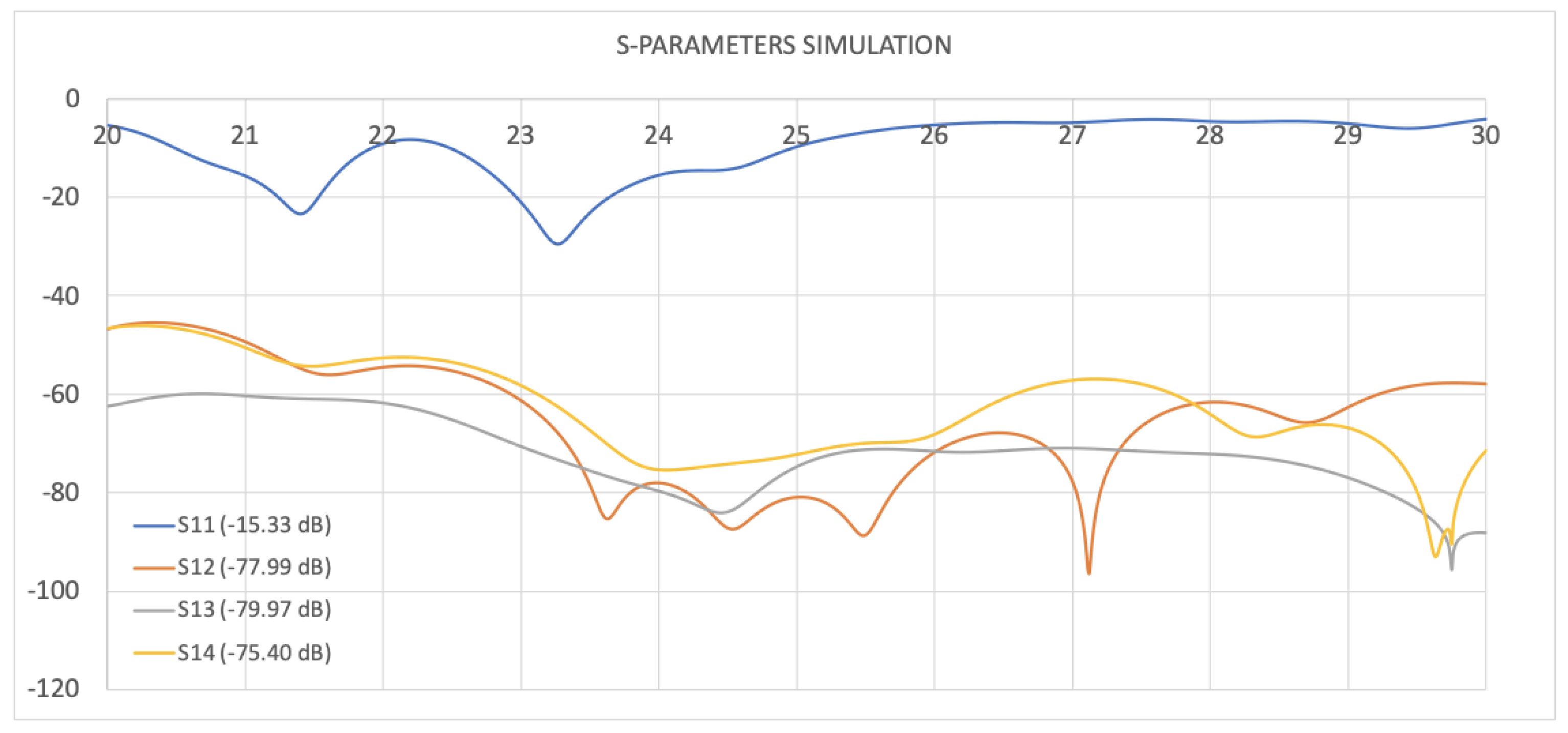
Figure 5.
radiation pattern.
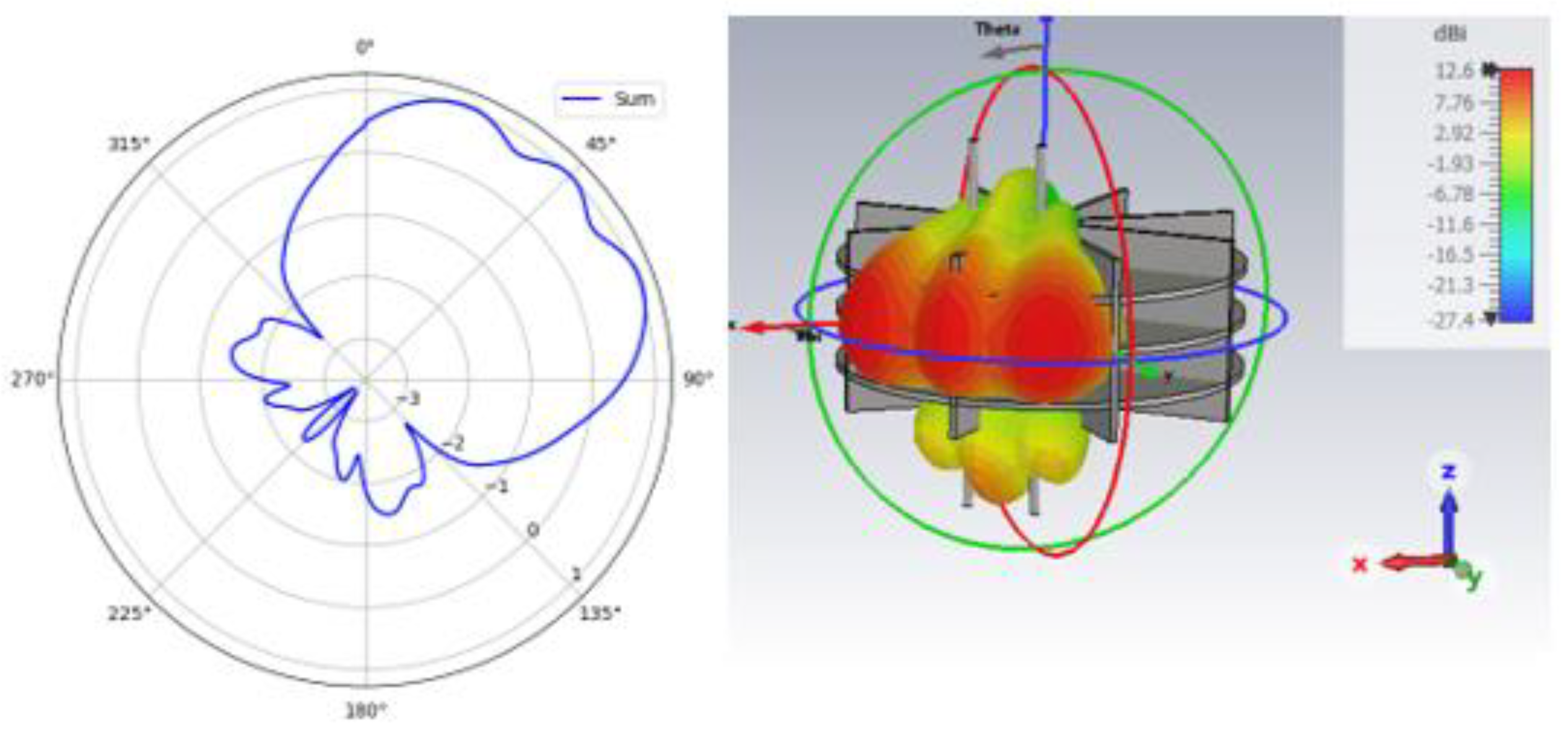
Figure 6.
radiation pattern.
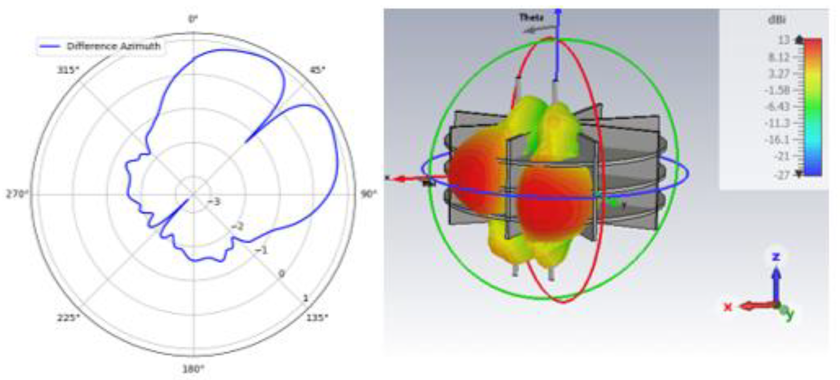
Figure 7.
radiation pattern.
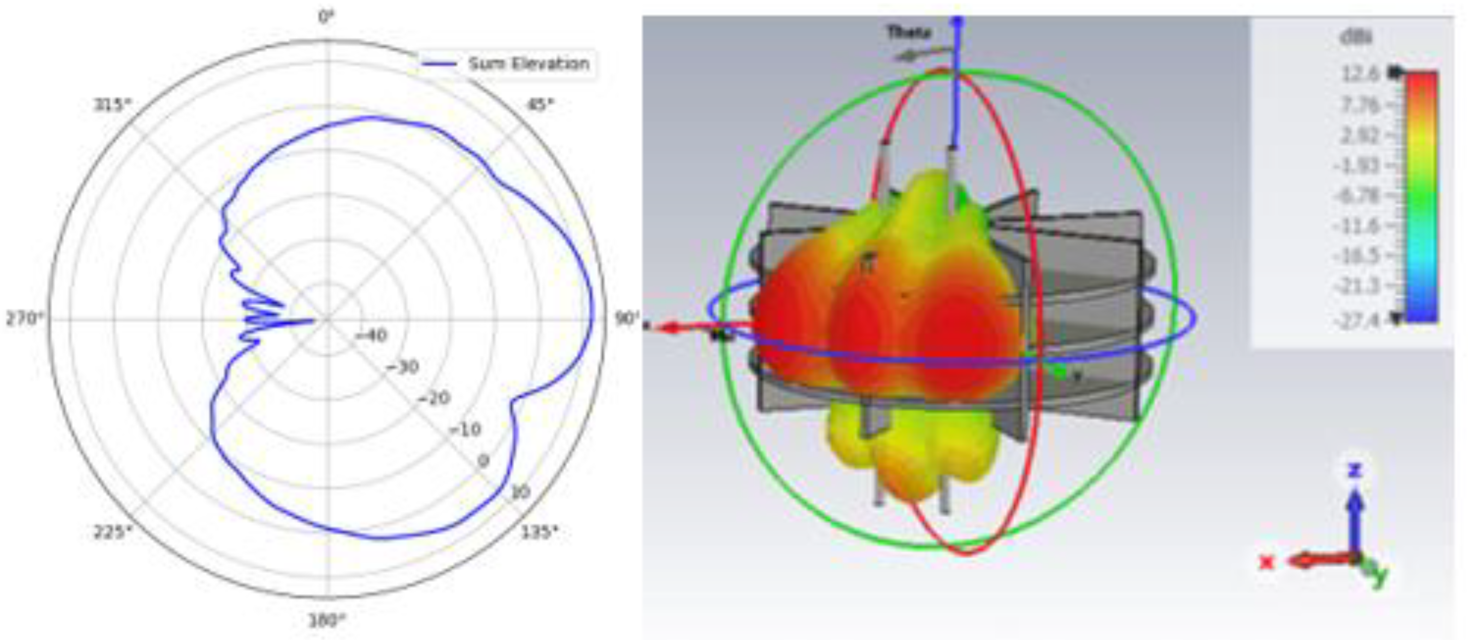
Figure 8.
radiation pattern.
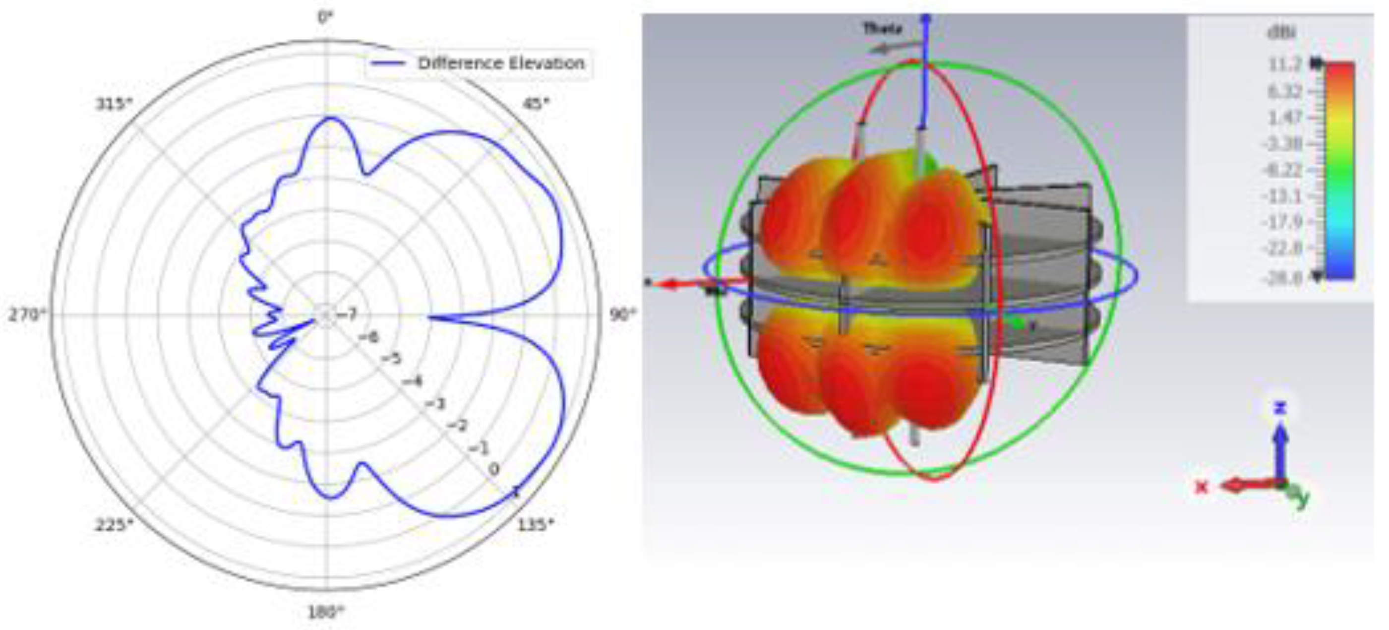
Figure 9.
Overlapped monopulse azimuthal coverage.
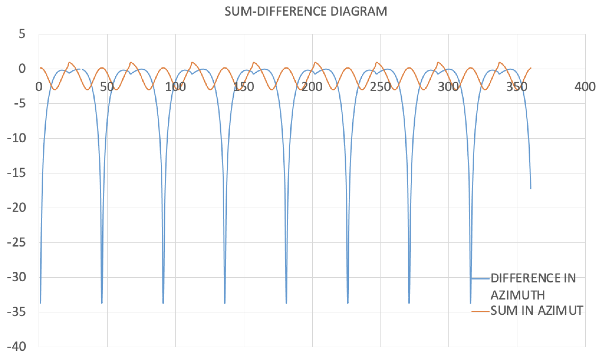
Figure 10.
Antenna prototype.
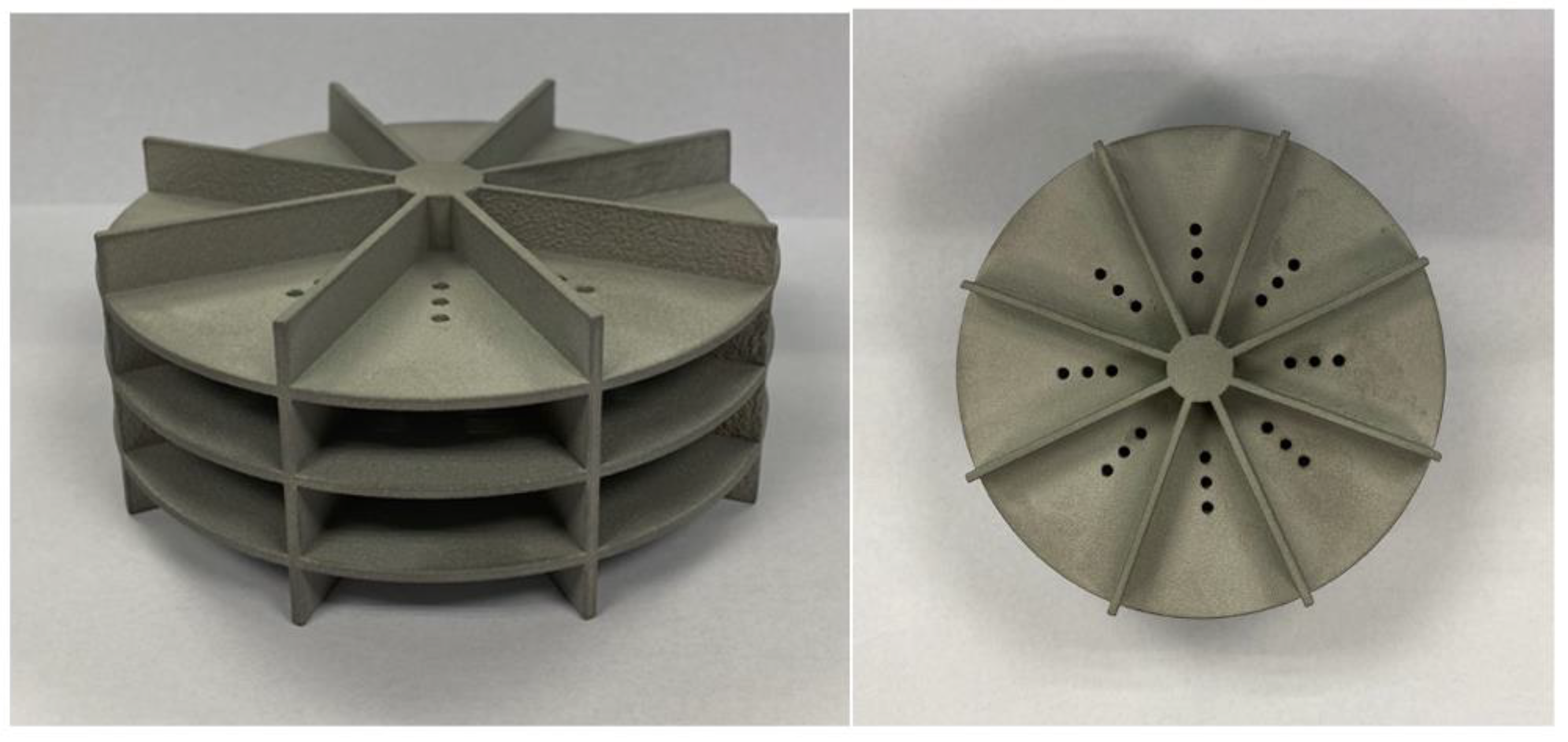
Figure 11.
Measurement setup in the anechoic chamber.
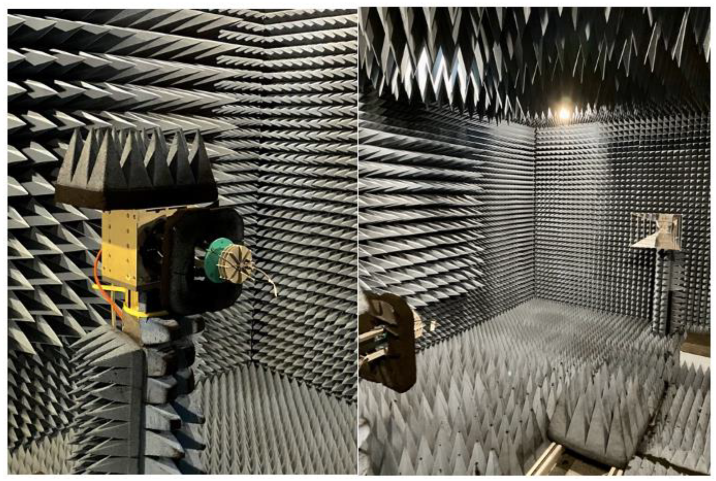
Figure 12.
Antenna S-parameters measured in the Anechoic Chamber.
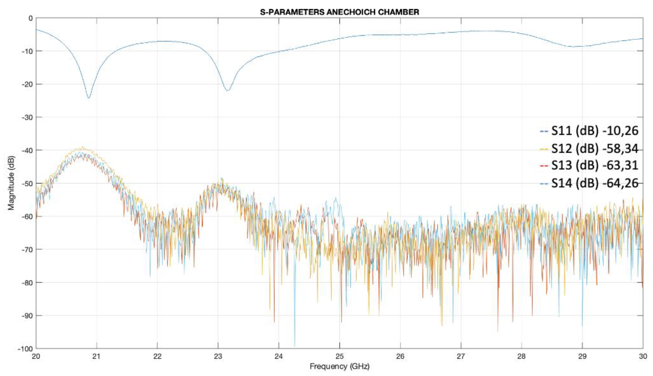
Figure 13.
Comparison of the simulated and measured diagrams on the horizontal plane.
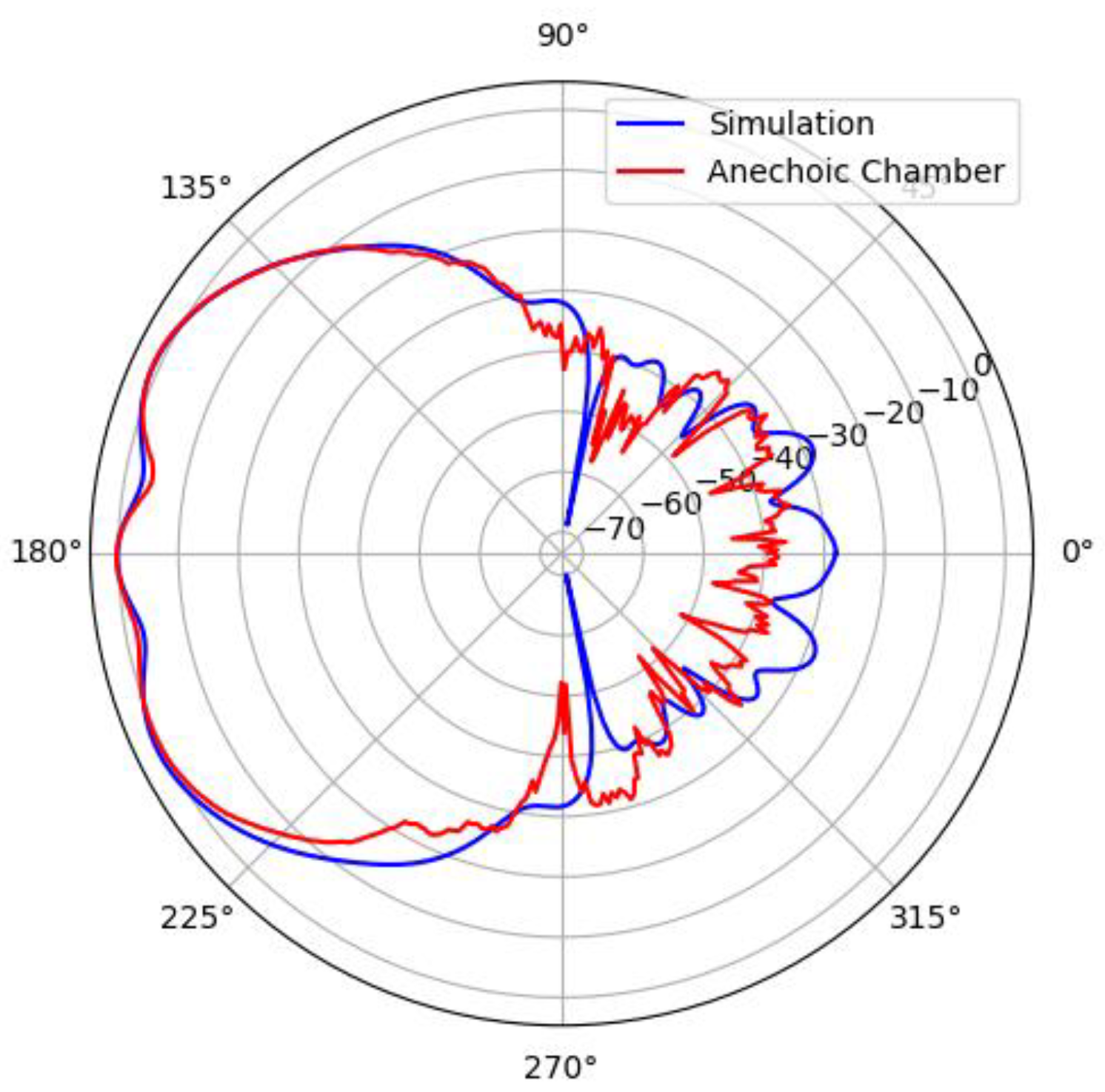
Figure 14.
Comparison of the simulated and measured diagrams on the horizontal plane.
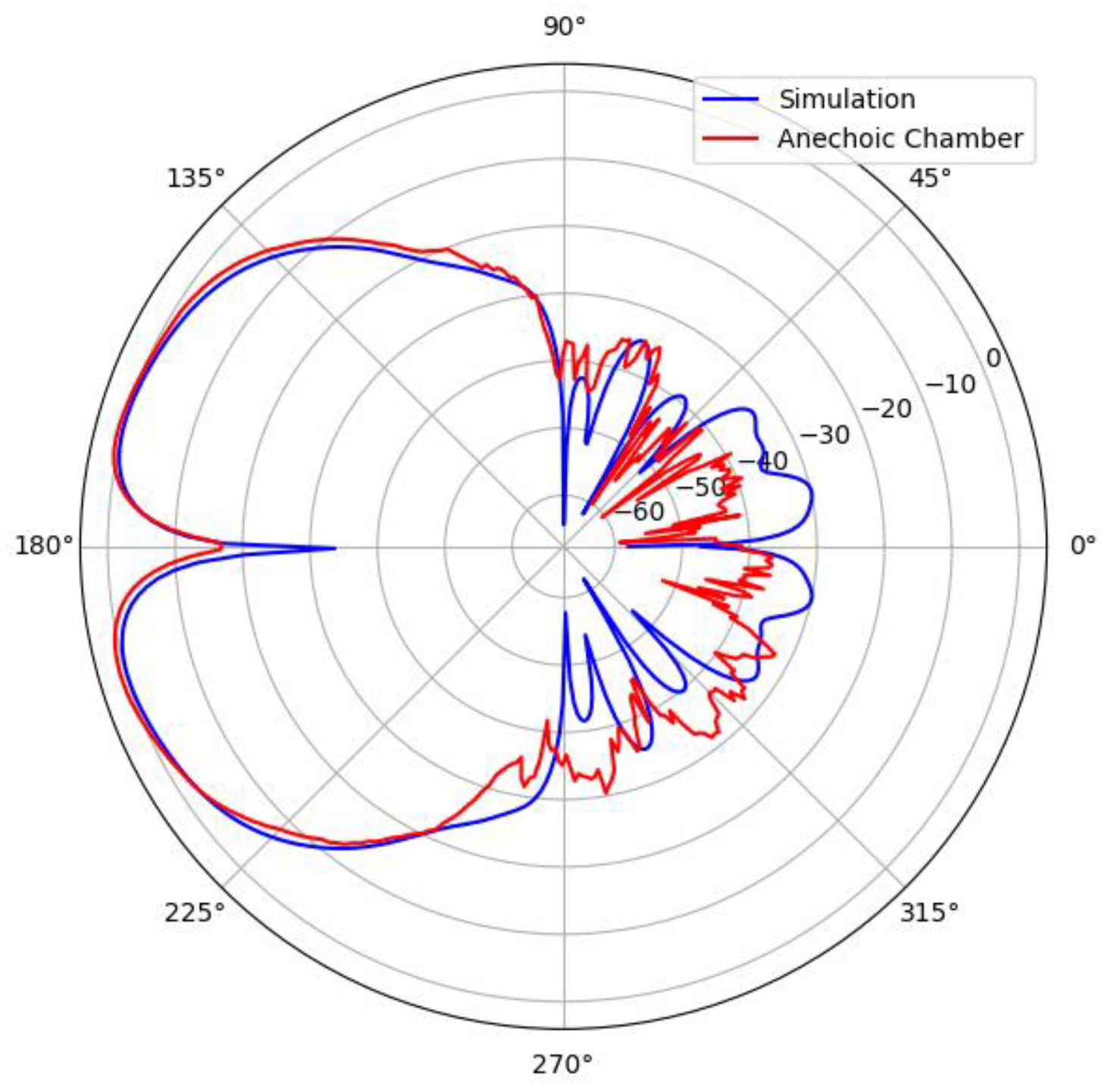
Figure 15.
Comparison of the simulated and measured patterns on the vertical plane.
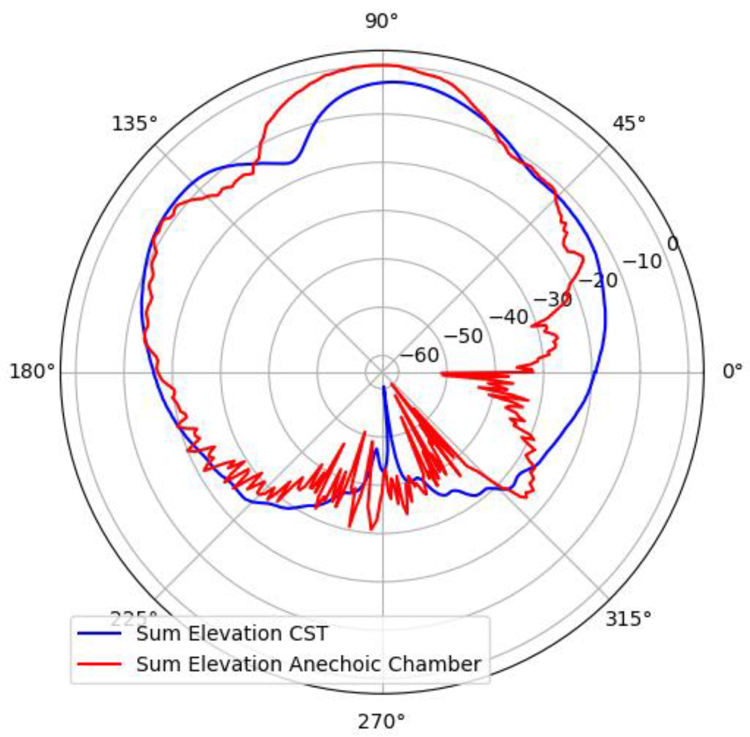
Figure 16.
Comparison of the simulated and measured patterns on the vertical plane.
Disclaimer/Publisher’s Note: The statements, opinions and data contained in all publications are solely those of the individual author(s) and contributor(s) and not of MDPI and/or the editor(s). MDPI and/or the editor(s) disclaim responsibility for any injury to people or property resulting from any ideas, methods, instructions or products referred to in the content. |
© 2025 by the authors. Licensee MDPI, Basel, Switzerland. This article is an open access article distributed under the terms and conditions of the Creative Commons Attribution (CC BY) license (http://creativecommons.org/licenses/by/4.0/).
Copyright: This open access article is published under a Creative Commons CC BY 4.0 license, which permit the free download, distribution, and reuse, provided that the author and preprint are cited in any reuse.


