
Submitted:
24 March 2025
Posted:
25 March 2025
You are already at the latest version
Abstract
This study evaluates the ballistic performance of composites reinforced with aramid fibers, focusing on the comparison between artisanal twill-structured fabrics (SKRC) and commercial plain-weave fabrics (TLRC). The composites were manufactured using a compression molding technique and subjected to ballistics tests with expansive hollow-point bullets, based NIJ 0108.01 standard. Key parameters analyzed included projectile deformation, delamination behavior, and the coverage factor of the fabrics. The SKRC composite exhibited superior ballistic performance, attributed to its higher coverage factor and enhanced interaction with primary yarns, resulting in greater energy absorption and bullet deformation. Conversely, the TLRC composite demonstrated limited resistance, with reduced delamination and inefficiency in dissipating kinetic energy. MO revealed distinct deformation profiles of the projectiles and delamination zones, correlating these behaviors with the reinforcement structure's mechanical response. These findings highlight the potential of artisanal twill-structured fabrics for ballistic applications, emphasizing the importance of reinforcement content and fabric architecture in improving composite performance. This study contributes to the advancement of terminal ballistics and the development of lightweight, high-performance materials for protective equipment. Future research should explore optimization of stacking sequences and reinforcement content to further enhance ballistic protection.
Keywords:
Ballistic protection
; Aramid Fabrics
; Terminal ballistic
; Composite
1. Introduction
Composite materials for ballistic applications have been a prominent focus of research for decades [1,2,3,4,5,6,7,8]. Since ancient times, humans have developed protective structures to mitigate injuries caused by various forms of physical combat [9]. With advancements in weaponry and ammunition, the need for lightweight, flexible, and high-energy-absorbing materials has become paramount. The 20th century marked a turning point in this field, with the discovery of advanced textile materials like para-aramid and UHMWPE, paving the way for innovative solutions in ballistic protection. [10; 11].
The evolution of military weaponry, tactics, and ammunition technology necessitated the development of advanced ballistic protection systems. These systems must not only provide effective protection against damage but also possess properties such as resistance, flexibility, lightness, and high energy absorption capacity. Technological innovations and manufacturing advancements in the 20th century led to the discovery of high-performance textile materials, such as para-aramid and UHMWPE fibers, revolutionizing the field of ballistic protection (9-13). Composite materials offer an alternative approach to developing advanced ballistic protection systems [11,12,14,15]. Defined as the combination of two or more materials with distinct mechanical behaviors, composites exhibit enhanced performance when compared to their individual components. The matrix encases the reinforcing component, establishing either a chemical or physical bond known as the interface [13,15,16]. The interface between the matrix and the fiber reinforcement is critical for dispersing the forces generated during ballistic impact. It facilitates energy dissipation through the interaction of the matrix and reinforcement, thereby decelerating the projectile and enhancing the composite’s resistance to impact energies. In this case, the fibers during the impact have as a fundamental element the friction present in the threads that are immediately positioned in the contact area of the projectile and the maximum load of distributed tension [5,17,18,19].
High-performance fibers with ballistic protection capabilities substantially reduce the weight of protective equipment. However, significant investment in research and advanced techniques is essential to analyze the mechanics of damage caused by projectile impacts. In addition, few researchers have also comprehensively analyzed and discussed various research papers on modelling and simulation, experimental testing, ballistic penetration resistance, projectile characteristics, failure modes of ballistic materials, and composites for different applications. [20,21,22,23,24,25,26,27].
According to Tocchetto [28], ballistic science is divided into external and terminal ballistics. External ballistics evaluates the forces acting on a projectile in motion and its trajectory, while terminal ballistics focuses on the behavior of a projectile upon impact with a target. Regarding external ballistics, two behaviors are present in the projectile's behavior: rotation and nutation. Rotation occurs when the projectile is expelled by the combustion of gunpowder and has its direction guided by the ray present in the barrel of firearms, nutation occurs when the tip of the projectile oscillates around an axis. The caliber of a weapon is determined by a few variables, such as the diameter of the case, the amount of gunpowder, the diameter and length of the projectile. In this way, calibers have a maximum and minimum value that qualify them in terms of the amount of kinetic energy the projectile achieves after being shot. The author also points out that two factors must be considered when talking about the damage caused by firearm projectiles: lethality and stopping power. Considering that every weapon can be lethal when evaluating the place where the projectile hit, while stopping power would refer to the number of shots needed for an aggressor to cease the violent act. This variable therefore considers not only where the attacker would be shot but, above all, the amount of energy transferred to the target on impact. If we consider projectiles of the same caliber, keeping the amount of gunpowder and the diameter of the projectile constant, and evaluate the behavior of projectiles with different geometries. For example, a projectile that expands on contact with the target will increase its area of contact and will therefore transfer more of its kinetic energy to the target.
Projectiles can be classified according to their geometry, as follows: ogival-OG, flat-topped-PP, semi-sharp-edged-SCV, sharp-edged-CV, expansive hollow-point-EXPO, fully jacketed-ET, obturated jacketed-EO and pointed-PT. Expanding hollow-point projectiles are made of lead, which is a soft, high-density metal. When it hits a target, it deforms, having grooves in its structure that guide the projectile's direction of deformation. Based on the representation in Figure 1 it is possible to observe the deformation of the projectile when fired at a fluid that is denser than air, in this case water [28].
The development of textile materials as reinforcement structures in polymer composites has been extensively studied within the field of structural materials. These studies have focused on the type of fiber used as well as their arrangement (geometry) in the polymer matrix, with the main characteristic being the individual properties of the constituents and their combination so that a new product can be developed. The area of textile engineering has a wide scope in terms of knowledge of fibers, their properties, and applications, since without fibers this area has no identity [23,24,29,30].
Aramid fibers are 43% lighter and twice as strong as glass fibers, while being ten times stronger than aluminum. Moreover, aramid fibers exhibit excellent thermal stability over a wide temperature range and retain their mechanical properties even when exposed to extreme conditions, such as temperatures as low as -196°C. Additionally, they have a melting point exceeding 427°C. Twaron is a para-aramid fiber made by the Japanese company Teijin. It has low creep, a high melting point, and good resistance to bending and abrasion [30,31]. Aramid is the material most found in relevant literature, as it is widely used in the manufacture of composite materials, especially for ballistic applications [2,9,13,23,24,25,26,27,30,31,32,33,34].
Fibers with high tensile strength and a high modulus of elasticity are capable of absorbing significant amounts of energy. Materials with a high tensile modulus and low density efficiently transmit shock waves from the impact point, distributing energy across a broader area and minimizing impact damage [19,29,30]. Most of the projectile's kinetic energy is transferred to the yarns that are directly in contact with the projectile, while the contribution of the orthogonal yarns to energy absorption is reduced [19,24,35,36,37]. Upon impact with a target, an expanding projectile deforms by increasing its diameter and reducing its length [24,28]. As the target resists penetration, the contact area between the projectile and the target grows, facilitating a broader propagation of kinetic energy, as shown in Figure 2 [25].
When a projectile impacts a fabric, the warp and weft yarns separate, creating a distinctive geometry known as a wedge [19,22,30,34], as shown in the images in Figure 3.
In the simulation carried out with the projectile and the fabric (Figure 3), it was possible to observe behavior similar to that reported by Liu (2021) [34], where the moment the projectile strikes that fabric, it comes into contact with the primary yarns, deforming and spreading apart the surrounding interwoven yarns. This interaction compresses the secondary yarns, forming an opening referred to as a wedge. As a result, the cross-sections of the yarns are deformed as the yarns are being compressed, and as consequence, the attachment points between the yarns are resistant to deformation. When a fabric is unbalanced, such as the twill structure, the fabric interlocks, causing its cross-sections to deform to avoid interference. This behavior is due to the shear of the fabric's yarns, which is a consequence of the formation of folds and ripples, providing a rigid elastic response, followed by a condescending response, where the yarns begin to rotate mainly due to friction. [18,19,33,34,35,36]
This interaction compresses the secondary yarns, forming an opening referred to as a wedge. Other factors to consider are the size of the ballistic projectile, its movement to form a cone on the rear face of the target, the shear of the projectile, the traction of the primary yarns of the composite, the elastic deformation of the secondary yarns, and the deformation of the projectile while it is in contact with the fabric. [30].
Aliverdipour (2020) [17] perforated different fabrics with different pointed geometries with perpendicular incidence on the fabric, with the angle of the perforating profile and the types of fabric used as variables. After the tests, the author concluded that the more acute angles were easier to pierce.
Fabrics behave in a singular pattern when faced with a type of stress, be it compression, in tensile or shear, but this response is possible due to the material's mobility. Since the fabric is integrated into a composite as a reinforcing structure, its behavior is also affected by the interface between the fiber and the matrix [35,36,37,38,39,40,41,42]. In a composite, the matrix is the initial point of impact for a projectile, propagating energy to the reinforcement fibers. In this way, the limiting conditions of the yarn during the transverse impact will have a direct influence on how the stress and energy will be distributed individually in the fibers. When a projectile impacts fabrics, two types of yarns play distinct roles. Primary yarns, or main yarns, directly interact with the projectile, inducing transverse deflection. Secondary yarns, while not in direct contact, assist in propagating longitudinal waves. During a high-velocity impact on fabric, the projectile displaces primary yarns, generating a longitudinal wave that propagates rapidly from the impact center along the yarn's axis [35]. From the longitudinal wave, the primary yarn moves towards the center of impact due to its deformation. As the fabric deforms, it maintains transverse deflection until the yarns reach their breaking stress. As the projectile penetrates the reinforcement layers, the interface influences the composite's behavior by affecting yarn compression and shear, effectively dissipating kinetic energy Figure 4. [21,26,27,39,40]
This study aims to manufacture and evaluate the influence of reinforcement structures on the ballistic performance of composites reinforced with aramid fibers, tested with hollow-point bullets. For this purpose, aramid fabrics were used as a reinforcing element in the form of a commercial plain weave fabric and a handcrafted twill fabric developed specifically for this work at the UFRN Fabric Laboratory.
2. Materials and Methods
The matrix employed was a pre-accelerated orthophthalic polyester resin supplied by IBEX Química Indústria e Comércio-Br, polymerized using Butanox M50 at a 1% v/v ratio.
The reinforcement materials included para-aramid fabric with a twill structure (SK), featuring a fabric weight of 369 g/m². This fabric was produced using a handloom machine in the Weaving Laboratory at UFRN, utilizing TWARON 2040 1100 Dtex yarn supplied by Teijin Aramid.
Commercial para-aramid fabric plain weave as structure (TL) supplied by Texiglass Indústria e Comércio Têxtil, Fabric weight of 187g/m². Figure 5 shows the images of the reinforcements used in the production of the composite and the characteristics of the reinforcements are described in Table.1.
The fabric manufacturing process encompassed the preparation of warp, weft, and weaving stages, utilizing artisanal equipment to produce the final product. Figure 6 shows the handloom process of producing the twill structure fabric.
The fabric weight is determined by the ratio of mass per unit area, calculated as the mass of the fabric per unit length and total width, in accordance with ABNT NBR 10591. To better understand the characteristics of fabrics used as reinforcements in composites, the coverage factor (k) is applied, as described in Equation 1. This parameter directly influences the impregnation of the reinforcement by the matrix during the lamination process."
This parameter is related to the proportion that a fabric is covered by warp or weft yarns, or both. Considering that a fabric is formed by the interweaving of warp and weft threads, during the weaving process there will always be a space for the other set of threads to interweave.
Were:
K = cover factor;
n = yarn/cm, (warp) or batidas/cm, se (trama);
Tt = linear density of the yarn in Tex
Thus, for any Cf we will have:
Where:
V = specific volume of the yarn, in cm3 / g;
Cf = fractional coverage (warp or weft).
When d=p, i.e., when Cf = 1.0, the fabric has maximum theoretical coverage. The coverage factor (k) for this particular case will be:
To provide a more accurate result, the formula in equation (6) is considered more appropriate:
Were:
Kt = cover factor of fabric;
K1 = cover factor of warp;
K2 = cover factor of weft.
The characteristics of the fabrics used are described in Table 1
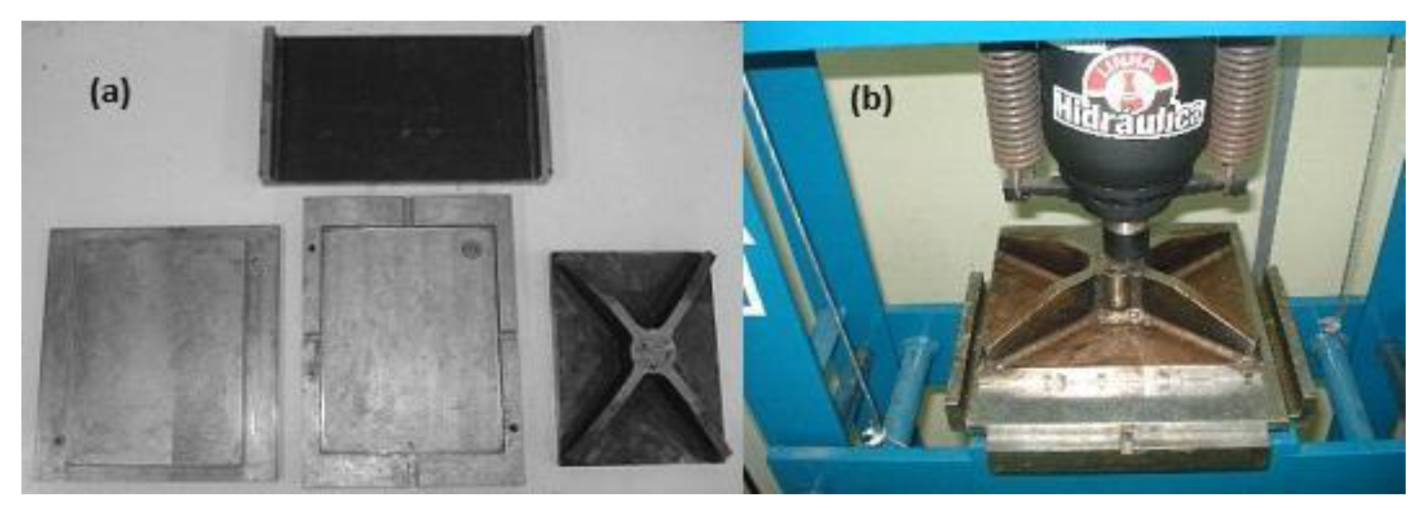
The composite was fabricated using the compression molding technique. It consisted of a laminate with four layers of twill fabric, developed with para-aramid fibers on a laboratory scale using a handloom machine, and eight layers of commercial fabric and the configuration of the composites as presented in Table 3.2 The polyester resin is catalyzed using Butanox M50 at 1% was poured over the fabrics. The mold closed and the system pressed less than 5 ton for 12h at room temperature figure x. After this stage, the closed mold was post-cured in an oven at a temperature of 70°C for 4 hours.
Figure 3.
4: a) steel mold; b) compression molding.
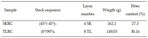
The configuration of the composites produced as showed in Table 2.

Table 2.
- Ballistic plate configuration: SKRC (twill fabric-reinforced composite); TLRC (plain weave-reinforced composite).
Table 2.
- Ballistic plate configuration: SKRC (twill fabric-reinforced composite); TLRC (plain weave-reinforced composite).
 |
The ballistic test was designed in accordance with NIJ 0108.01, which outlines the firing parameters specified in the standard. The test used. 38 SPL +P+, EXPO/SJHP ammunition produced by CBC, supplied by the General Command of the RN Military Police. Figure 7 shows the dimensions of the plate and the positioning of the target for the test.
In order to assess the propagation of the impact waves after the shot and consequently the level of damage to a “soft” body, i.e., to obtain the standard deformation of the projectile. For this purpose, Italian-made Roma DAS No. 1 ballistic clay was used. The composites were positioned in a pine wood box measuring 1.2 m x 0.40 m x 1.15 m, with a frame for fixing the target, ballistic plate, and ballistic clay. Three tables were used for positioning the target and the test, two measuring 0.60m x 0.40m x 1.15m for positioning the chronograph support and one measuring 0.40m x 0.40m x 1.15m for positioning the target and plasticine, as shown in Figure 8.
The chronographs used were the Prochrono DLX model manufactured by Competition Electronics, with the first chronograph 2 meters away from the shooter and 1 meter away from the second chronograph, which in turn was 2 meters away from the target. According to the shooter, normally projectiles tend to lose altitude after hitting a target. For safety reasons, a chronograph was not used behind the target, but rather 2 tires for projectile recovery in the event of a perforation of the ballistic plates. The test was conducted by the PM/RN with weapons and ammunition from the corporation and qualified shooter.
Post-ballistic testing, the composites were assessed for the extent of post-impact damage and the morphological changes in the projectiles. The evaluation of the level of damage to the plates, the entry and exit diameters of the projectiles, were measured using a Vinwer digital pachymeter where the maximum diameter (Dmax) and minimum diameter (Dmin) were measured on the front and rear views of the ballistic plates.
Optical microscopy analyses were carried out at the Rio Grande do Norte Police Criminalistics Institute (ITEP-RN) using a Leica FS-M microscope. In order to evaluate the delamination of the composite after ballistic impact, samples were cut using a machine with a vibrating disk, and the images were evaluated at magnifications of 4X, 10X, 20X, and 40X, observing the front, back, and side views of the plates. Free image software was used to delineate the delamination zones and thus measure the area and perimeter. A 4X magnification was used to evaluate the deformation of the bullet after the shooting test on the composites and the projectile fired in ballistic clay was used as a parameter for comparing the composites
Feret index, Equation 3, was used to measure the ratio between the largest diameter (Dmax) and the smallest diameter (Dmin) of a delamination resulting from the impact of the projectile on the ballistic plate. This analysis was carried out using the images obtained by optical microscopy and the free Imaje.JS software to demarcate the delamination zones, thus making it possible to measure the morphology of the deformation represented by the delamination. If, Feret index was closer to 1 the more homogeneous the impact dispersion and the closer to 0 the more heterogeneous this dispersion.
3. Results
To compare and understand the ballistic behavior of the composites, a projectile was fired at ballistic clay. This material, which reproduces the behavior of soft tissues in the human body, was used to analyze the deformation profile of an expanding hollow-point bullet after impact.. The images shown in Figure 9 and 10 refer to the deformation of the plasticine and the projectile, respectively.
The images showed a standard circular entry hole (a) and a conical exit (b) in the ballistic clay, characteristic of the behavior of soft tissues, such as those in the human body. It is also possible to see brown particles, highlighted in red in image (b), which are the result of the projectile friction on the plasticine. The deformation profile of the bullet was evaluated using optical microscopy at 4X magnification. The analysis showed a mushroom-shaped deformation, characteristic of soft body impacts, as reported in the literature [29].
Following the ballistic testing of the composites, the entry and exit diameters of the projectiles were measured, as detailed in Table 3 and Figure 11."
As presented in Table 3, the SKRC and TLRC composites displayed slight differences in their inlet diameters, while their outlet diameters remained comparable. However, when we look at the images in Figure 12, despite the projectile having transfixed the plate, in the projectile entry profile (a), it is possible to see darkened yarns due to the impact of the projectile, as well as the rupture with contraction of the primary and secondary yarns of the reinforcement structure. Additionally, a delamination region, caused by the dissipation of energy from the projectile's impact on the composite, was observed. This phenomenon is linked to the influence of the reinforcement structure on the composite's mechanical response to high-velocity impacts. When analyzing the projectile exit profile at (b), we see fibrillation characteristic of aramid fiber and a substantial increase in the exit diameter. This behavior is expected due to the expansion capacity of the projectile used, as well as the fact that the reinforcement structure is a balanced mesh with a low coverage factor. The side view (c) shows the delamination of the composite after the ballistic impact, red highlight in the image.
Based on the images in Figure 13 (a), the projectile's entry profile follows the diagonal direction characteristic of the twill structure, with more breaks in the primary threads than in the secondary threads. Compared to the TLRC composite, Figure 12, this behavior can be associated with the fact that the twill structure has 5 times more primary yarns than the flat fabric structure, and consequently the coverage factor of the twill is much higher Table.1. The back view (b) shows the formation of a cone without an exit hole due to the deformation of the fibers caused by the impact. It is also important to mention that, during this test, the bullet was recovered in front of the plate, indicating that the reinforcement structure acted as an energy-absorbing element. In this way, the exit hole can be associated with the impact waves resulting from the expansion of the projectile. When viewing the side profile of the plate (c), the delamination of the plate after the ballistic impact is clearly visible.
Based on the graphs shown in Figure 14, it is possible to correlate the deformation of the projectile in each composite studied in order to establish comparative parameters with both the microscopy of each composite (Figure 12 and Figure 13) and the optical microscopy images of the projectiles after shooting (Figure 15 and Figure 16). The projectile impacting the TLRC composite plate exhibited a 44.44% reduction in length and the smallest total diameter increase, measuring 22.50%. This behavior may be attributed to the reinforcement structure, plain weave, being inefficient at deforming the expansive hollow-point bullet. Thus, as it interacts with the body and finds resistance, it increases its diameter area and decreases its length. Consequently, this composite showed low resistance to ballistic impact, with perforation of the plate by the projectile. The deformation analysis of the projectile impacting the SKRC composite plate revealed a 48.33% reduction in length, demonstrating the greater efficiency of this composite's reinforcement structure. These findings are supported by the analysis of the delamination area and perimeter variations, along with the Feret index, as presented in Table 4 and Table 5
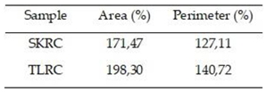
The data for the TLRC composite indicate a smaller entry delamination area compared to the other studied composites. This suggests lower resistance to stopping the projectile, as evidenced by the limited delamination. This behavior can be attributed to a low distribution of the efforts made by the matrix, with consequent poor action of the reinforcement structure during the ballistic impact. Similarly, the increase in the exit area with respect to the entry area indicates that there was a conical propagation of the delamination, but if we analyze the Feret index of both the entry and exit delamination, it can be seen that this composite has isotropic properties. However, for the SKRC composite, the low Feret index indicates inhomogeneous delamination distribution, reflecting the material's anisotropic properties. It is also possible to see that despite an increase of 171.47% in its delamination area, this material has the largest initial delamination area. This behavior indicates that from the moment the projectile struck the composite, it exhibited resistance to perforation.
4. Conclusions
The results of this study demonstrate the feasibility of using artisanal twill-structured fabric as a reinforcing element in ballistic composites, offering efficient ballistic protection. In this context, it can be concluded that the reinforcement structure behaves differently when in contact with an expansive .38 hollow-point projectile, taking as a parameter the morphology of the projectile after impacting the composite, where it was observed that the coverage factor of the fabrics used was an important parameter in understanding the results. Another factor of great importance is related to the bullet's entry profile, in which damage follows the direction of the fabric structure that reinforces the composite.
Plain woven fabric is not interesting for use as a reinforcing element in ballistic composites. Considering that, in the case of this study, the stacking sequence (0/90) was used to produce the TLRC composite, the reinforcement structure did not act satisfactorily in absorbing and dissipating the energy of the projectile impact, causing the sample to be perforated with a high level of damage, with deformation in the diameter of the projectile much lower than that of the ballistic clay.
The SKRC sample, composed of twill-structured fabric, effectively absorbed the bullet's impact, even with a low reinforcement content of 27.3%. This behavior is attributed to the fabric's higher coverage factor, which enhanced interaction with the primary yarns in the reinforcement structure. Consequently, the SKRC composite exhibited greater deformation of the projectile diameter compared to TLRC composites. These findings suggest that increasing the reinforcement content or optimizing the fabric stacking sequence could further improve its ballistic protection efficiency.
The analysis of the projectile's deformation profile is a critical parameter for interpreting results. This study demonstrates the utility of terminal ballistics in evaluating the behavior of ballistic composites.
Author Contributions
Conceptualization, P.T.L.; methodology, P.T.L; J.M.S and J.R.A.O; validation, P.T.L; C.H.R.B; W.W; formal analysis, V.M.F., E.P.C.F; P.T.L; C.H.R.B; W.W.; writing—original draft preparation, P.T.L.; writing—review and editing, V.M.F; E.P.C.F.; supervision, V.M.F and E.P.C.F. All authors have read and agreed to the published version of the manuscript.
Funding
This research was funded by the Brazilian Research Agencies: CAPES.
Institutional Review Board Statement
Not applicable.
Data Availability Statement
Not applicable.
Acknowledgments
The authors are indebted to PMRN for ammunitions donations and shooting area, and ITEP RN for laboratory support. I would also give a special thanks to Teijin Aramid for donating the 2040 Twaron yarn.
Conflicts of Interest
The authors declare no conflict of interest.
Abbreviations
The following abbreviations are used in this manuscript:
| TL | Aramid fabric plain weave |
| SK | Aramid fabric twill structure |
| SKRC | twill fabric-reinforced composite |
References
- Abtew MA, Boussu F, Bruniaux P, Loghin C, Cristian I. Ballistic impact mechanisms – A review on textiles and fibre-reinforced composites impact responses. Composite Structures 2019, 223, 110966. [Google Scholar] [CrossRef]
- Weerasinghe D, Bambach MR, Mohotti D, Wang H, Jiang S, Hazell PJ. Development of a Coated Fabric Armour System of Aramid Fibre and Rubber. Thin-Walled Structures 2022, 179. [Google Scholar]
- Wang Z, Zhang H, Dong Y, Zhou H, Huang G. Ballistic performance and protection mechanism of aramid fabric modified with polyethylene and graphene. International Journal of Mechanical Sciences 2023, 1, 237. [Google Scholar]
- Vargas-Gonzalez LR, Gurganus JC. Hybridized composite architecture for mitigation of non-penetrating ballistic trauma. International Journal of Impact Engineering 2015, 86, 295–306. [Google Scholar] [CrossRef]
- Shaktivesh, Nair NS, Naik NK. Ballistic impact behavior of 2D plain weave fabric targets with multiple layers: Analytical formulation. International Journal of Damage Mechanics 2015, 24, 116–50. [Google Scholar] [CrossRef]
- Roberts, J. C., Ward, E. E., Merkle, A. C.,; O’Connor, J. V. Assessing behind armor blunt trauma in accordance with the National Institute of Justice Standard for Personal Body Armor Protection using finite element modeling. Journal of Trauma and Acute Care Surgery 2007, 62, 1127–1133. [Google Scholar] [CrossRef] [PubMed]
- Nunes LM, Paciornik S, d’Almeida JRM. Evaluation of the damaged area of glass-fiber-reinforced epoxy-matrix composite materials submitted to ballistic impacts. Composites Science and Technology 2004, 64, 945–954. [Google Scholar] [CrossRef]
- Chu TL, Ha-Minh C, Imad A. A numerical investigation of the influence of yarn mechanical and physical properties on the ballistic impact behavior of a Kevlar KM2® woven fabric. Composites Part B: Engineering 2016, 95, 144–54. [Google Scholar] [CrossRef]
- Strelko, O.,; Horban, A. Analysis of the history of creation and improvement of personal protective equipment: from bronze armor to modern bulletproof vests. History of science and technology 2023, 13, 201–222. [Google Scholar] [CrossRef]
- Charters, E., Houllemare, M., & Wilson, P. H., A global history of early modern violence. Manchester University Press, Manchester UK, 2020,1-8.
- Bian J, Dai K, Lv X, Huang Z, Wu G, Zhang Y., Effect of Material and Structure of Ultra-High-Molecular-Weight Polyethylene Body Armor on Ballistic Limit Velocity: Numerical Simulation, Polymers, 2024, 16(21), 2985.
- Yordan Kyosev; Modelling approaches for constructing the geometry of textiles at the mesoscale level. In Multi-scale continuum mechanics modelling of fibre-reinforced polymer composites. Van Paepegem, W. (Ed.). Woodhead Publishing, UK, 2020, 79-103.
- M. N. Mohammed, Salah Al-Zubaidi, Siti HumairahKamarul Bahraim, S.M.Sapuan, State of the art review on recent advances and perspectives of ballistic composite materials. In Composite solutions for ballistics. Nawab, Y., Sapuan, S. M., & Shaker, K. (Eds.), Woodhead Publishing, UK, 2021, 3-54.
- Hazell, P. J., Armour: materials, theory, and design. CRC press 2ED, 2023, London.
- Alagumalai, V., Shanmugam, V., Balasubramanian, N. K., Krishnamoorthy, Y., Ganesan, V., Försth, M., ... & Das, O., Impact response and damage tolerance of hybrid glass/kevlar-fibre epoxy structural composites, Polymers, 2021, 13(16), 2591.
- Bandaru AK, Vetiyatil L, Ahmad S., The effect of hybridization on the ballistic impact behavior of hybrid composite armors, Composites Part B: Engineering, 2015, 300–319.
- Aliverdipour N, Ezazshahabi N, Mousazadegan F., Characterization of the effect of fabric’s tensile behavior and sharp object properties on the resistance against penetration, Forensic Science International, 2020, 1, 306.
- Bajya M, Majumdar A, Butola BS., Criticality of inter-yarn friction in high-performance fabrics for the design of soft body armour, Composites Communications, 2022, 1, 29.
- Cheeseman BA, Bogetti TA., Ballistic impact into fabric and compliant composite laminates, Composite Structures, 2003, 61(1–2), 161–73.
- Chen X, Zhou Y, Wells G., Numerical and experimental investigations into ballistic performance of hybrid fabric panels, Composites Part B: Engineering, 2014, 58, 35–42.
- Cheon J, Lee M, Kim M., Study on the stab resistance mechanism and performance of the carbon, glass and aramid fiber reinforced polymer and hybrid composites, Composite Structures, 2020, 15; 234.
- Courtney, A., & Courtney, M. (2008). A thoracic mechanism of mild traumatic brain injury due to blast pressure waves. Nature Precedings, 1-1.
- Fonseca VM, Marinho, Lima GS, Lima, Performance Mechanical of Polyester Composites Reinforced By Plain Woven Based On Aramid Fiber, International Journal of Engineering Research and Applications, 2023;13(6),123–129.
- Fonseca, V. M., Oliveira, E. J. P. A., Lima, P. T., & Carvalho, L. H., Development of Kevlar composites for ballistic application. In 4th Brazilian Conference on Composite Materials proceedings, 2018, July, Rio de Janeiro, Brazil, 548-553.
- Zhang, R., Song, X. T., Zheng, B. Q., Huang, J. H., Deng, J., Ni, C. Y., Wang, X. Effect of hybrid strategies on the ballistic response of aramid/ultra-high molecular weight polyethylene woven fabrics. Textile Research Journal 2024, 94, 1220–1232. [Google Scholar] [CrossRef]
- Naik S, Dandagwhal RD, Kumar Loharkar P. A review on various aspects of Kevlar composites used in ballistic applications. Materials Today: Proceedings. 2020. 21 Available from: www.sciencedirect.comwww.materialstoday.com/proceedings.
- Zhou H, Min S, Chen X., A numerical study on the influence of quasi-isotropic structures on the ballistic performance of para-aramid woven composites, Composite Structures, 2021, 275, 114489.
- Tocchetto, D., Balística Forense: aspectos técnicos e jurídicos, 9 Ed, 2018, Ed. Millenium, Brasil.
- Horrocks, A. R., & Anand, S. C. (Eds.). Handbook of technical textiles., 2000, Woodhead publishing Limited, Cambridge London.
- Kirkwood, John E., et al., "Yarn pull-out as a mechanism for dissipating ballistic impact energy in Kevlar® KM-2 fabric: part II: predicting ballistic performance, Textile research journal, 2024, 74(11), 939-948.
- Gonzalez, G. M., Ward, J., Song, J., Swana, K., Fossey, S. A., Palmer, J. L., ... & Parker, K. K., Para-aramid fiber sheets for simultaneous mechanical and thermal protection in extreme environments, Matter, 2020 3(3), 742-758.
- Revaiah RG, Kotresh TM, Kandasubramanian B., Studies on properties of coated para-aramid fabric samples developed for military applications–post UVA-340 exposure, Journal of the Textile Institute, 2024, 115(4),581–592.
- Gilson L, Rabet L, Imad A, Coghe F., Experimental and numerical assessment of non-penetrating impacts on a composite protection and ballistic gelatine, International Journal of Impact Engineering, 2020, 136.
- Liu Y, Zhang H, Huang G, Zhou H, Chen J, Wang Z., Theoretical model for predicting stabbing resistance of soft body armor comprising fibrous composites, International Journal of Impact Engineering, 2023, 180.
- Zhou Y, Chen X, Wells G., Influence of yarn gripping on the ballistic performance of woven fabrics from ultra-high molecular weight polyethylene fibre, Composites Part B: Engineering, 2014, 62, 198–204.
- Li H, Zhang R, Min S, Zhou Y, Sun J. Parametric study on the ballistic performance of seamed woven fabrics. Defence Technology 2023, 24, 173–189. [Google Scholar] [CrossRef]
- Li Z yong, Xue Y song, Sun B zhong, Gu B hong. Ballistic penetration damages of hybrid plain-woven laminates with carbon, Kevlar and UHMWPE fibers in different stacking sequences. Defence Technology 2023, 26, 23–38. [Google Scholar] [CrossRef]
- Shrivastava, R., Singh, K. K., & Gaurav, A., Mechanical and termal Properties of synthetic /synthetic fibers in hybrid woven fabric polymeric composites in Innovations in Woven and Non-Woven Fabrics Based Laminated Composites, Eds SanjayMavinkereRangappa, Vinod Ayyappan, Jiratti Tengsuthiwat, Suchart Siengshin, Composite Science Technology, 2025, Springer, Singapure 173-198.
- Yang CC, Ngo T, Tran P., Influences of weaving architectures on the impact resistance of multi-layer fabrics, Materials and Design. 2015, 85, 282–295.
- Cronin, D. S. , Application of a detailed thorax model to investigate behind armour blunt trauma. In IRCOBI Conference Proceedings Dublin, Ireland, set 2012.
- Kędzierski P, Morka A. A comprehensive approach to the modeling and simulation of ballistic textiles. Composite Structures. 2022, 292, 115643. [Google Scholar] [CrossRef]
- King MJ, Jearanaisilawong P, Socrate S. A continuum constitutive model for the mechanical behavior of woven fabrics. International Journal of Solids and Structures 2005, 42, 3867–3896. [Google Scholar] [CrossRef]
Figure 1.
Bullet hollow point [28].
Figure 1.
Bullet hollow point [28].
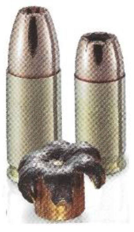
Figure 2.
- Simulation of wave propagation and deformation of a projectile in a ballistic impact [25].
Figure 2.
- Simulation of wave propagation and deformation of a projectile in a ballistic impact [25].
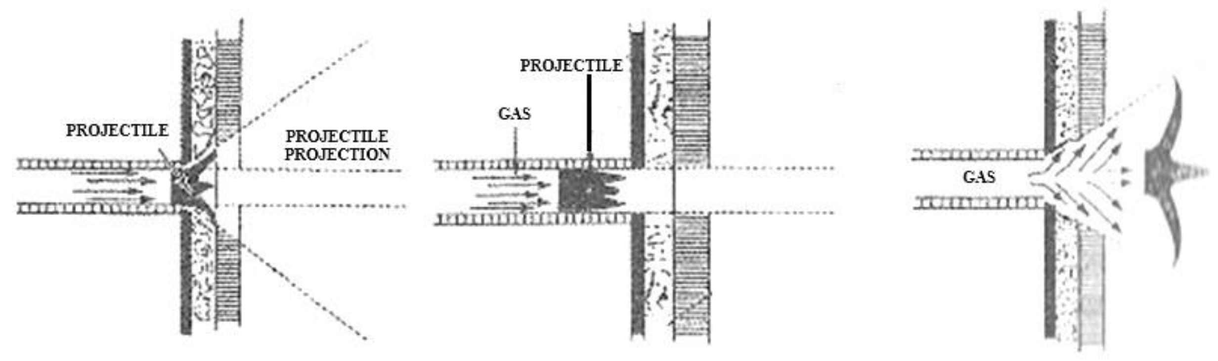
Figure 3.
Simulation of the fabric's deformation in contact with a projectile.
Figure 4.
-Representation of ballistic impact on fabric [40].
Figure 4.
-Representation of ballistic impact on fabric [40].
Figure 5.
- Figure 3.1 - Fabrics used as reinforcements in the composites - SK – artisanal Twill Structure; TL – commercial Plain weave Structure.
Figure 5.
- Figure 3.1 - Fabrics used as reinforcements in the composites - SK – artisanal Twill Structure; TL – commercial Plain weave Structure.
Figure 6.
(a) weft production; (b) handloom machine; (c) fabric produced.
Figure 7.
- Composite plate size and target location.
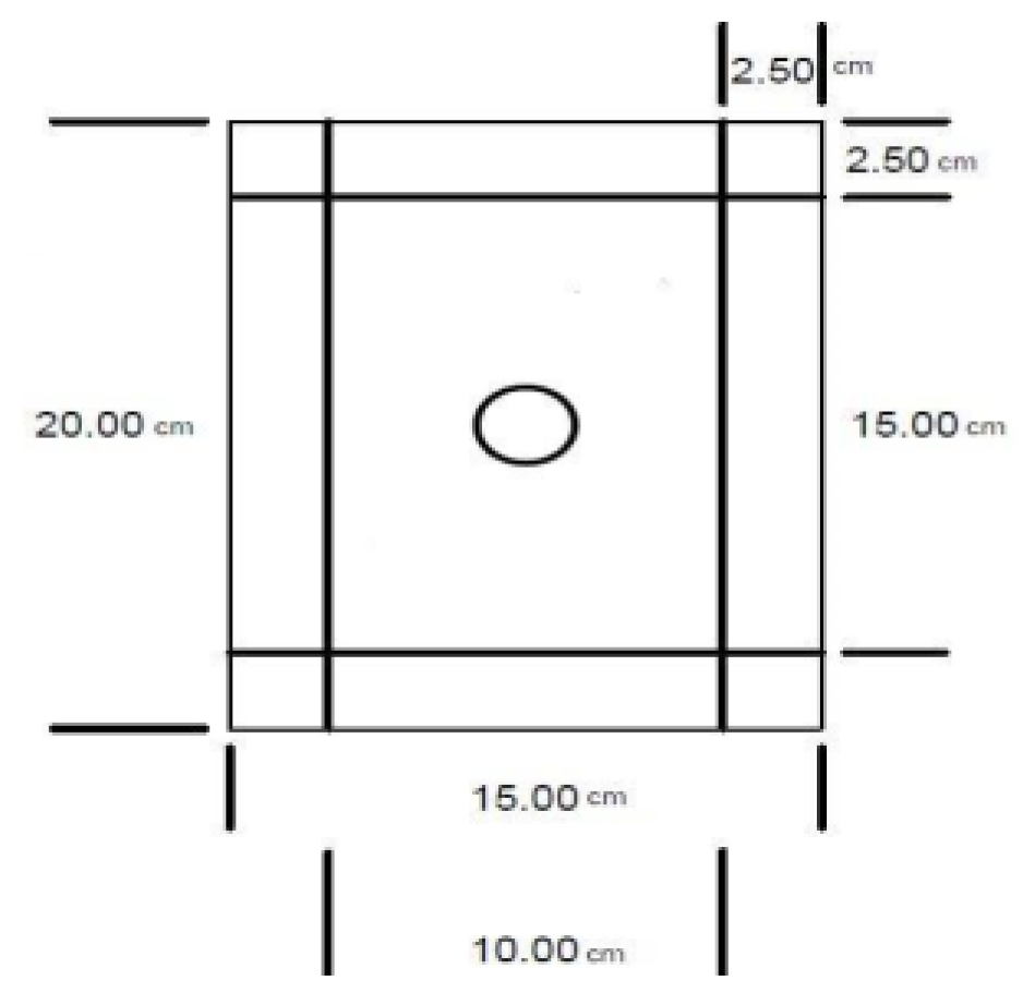
Figure 8.
- Ballistic test layout - Arrangement of tables and apparatus.
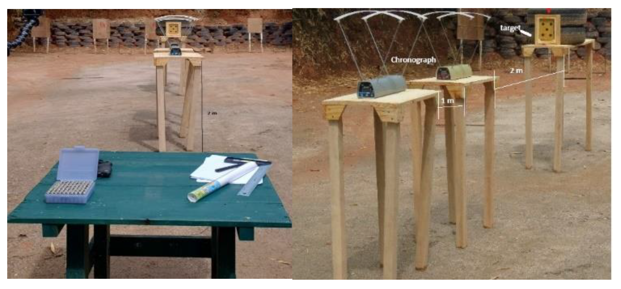
Figure 9.
- Ballistic clay after bullet shoot (a) frontal view, (b) posterior view.
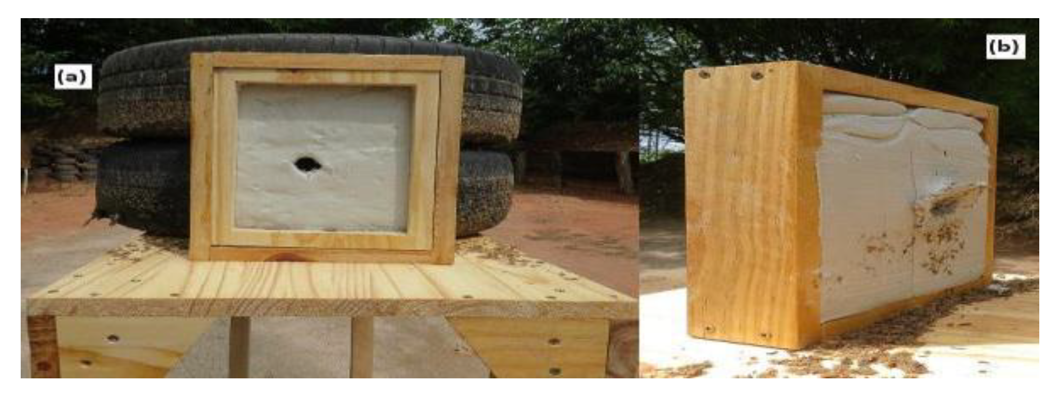
Figure 10.
- Optical microscopy of the bullet after impacting the ballistic clay at 4X magnification - (a) frontal view, (b) posterior view, (c) lateral view.
Figure 10.
- Optical microscopy of the bullet after impacting the ballistic clay at 4X magnification - (a) frontal view, (b) posterior view, (c) lateral view.
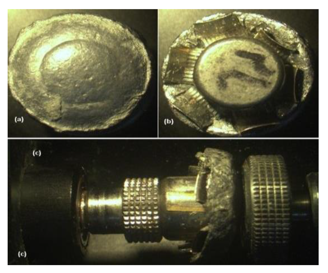
Figure 11.
-Measures of composite delamination after ballistic impact.
Figure 12.
- Optical microscopy of TLRC composite after ballistic test (a) front view, (b) back view c) side profile view.
Figure 12.
- Optical microscopy of TLRC composite after ballistic test (a) front view, (b) back view c) side profile view.
Figure 13.
- Optical microscopy of SKRC composite after ballistic test (a) front view, (b) back view, (c) profile side view.
Figure 13.
- Optical microscopy of SKRC composite after ballistic test (a) front view, (b) back view, (c) profile side view.

Figure 14.
Bullet deformation after impact in relation to the original size (a) and diameter of the projectile (b).
Figure 14.
Bullet deformation after impact in relation to the original size (a) and diameter of the projectile (b).
Figure 15.
- Optical microscopy of the .38 SPL EXPO bullet -4X.
Figure 16.
- Optical microscopy of the bullet after impacting the SKRC composite (a) front view, (b) back view, (c) side view.
Figure 16.
- Optical microscopy of the bullet after impacting the SKRC composite (a) front view, (b) back view, (c) side view.
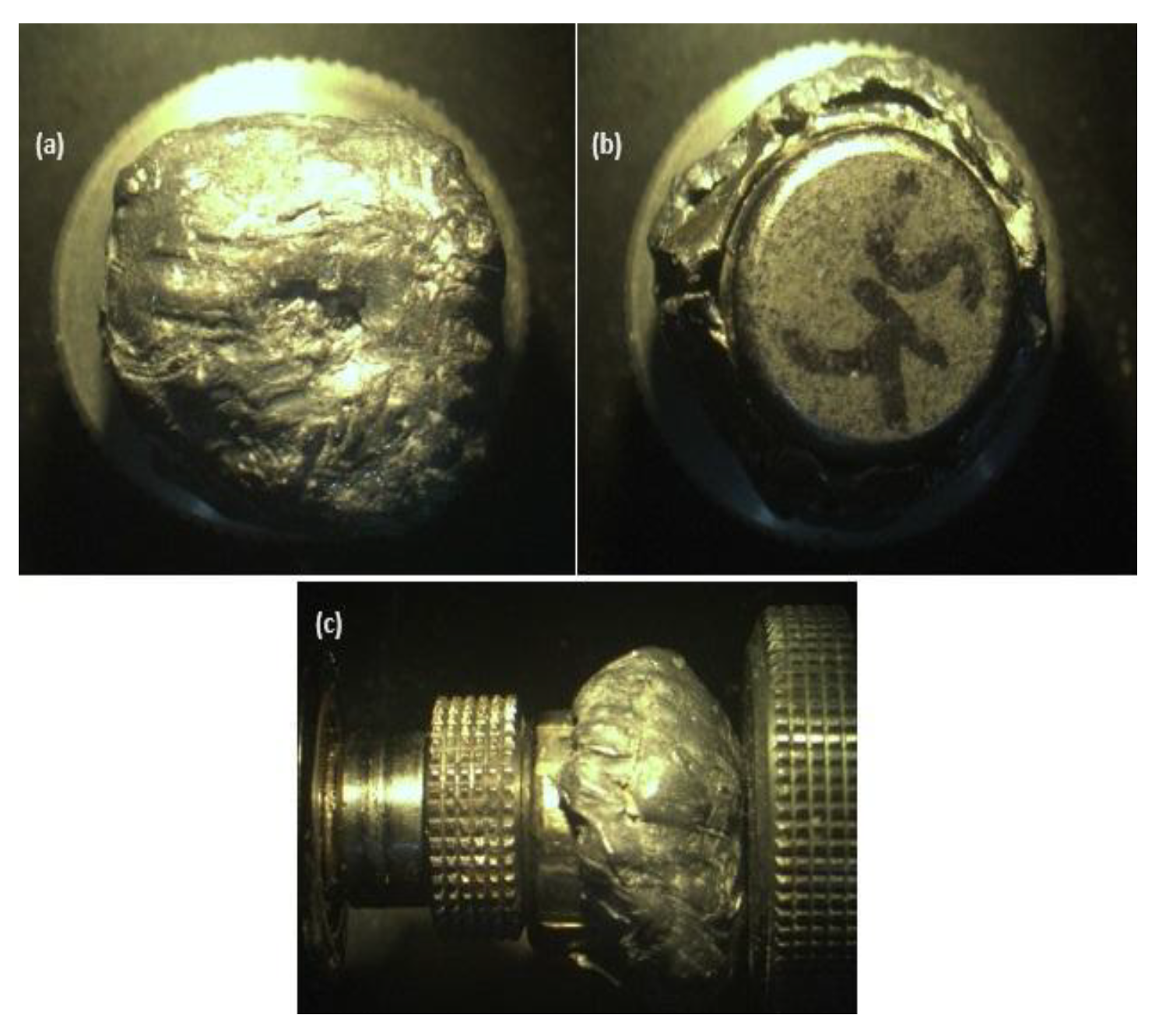
Table 1.
Data sheet of fabrics used as reinforcements in composites.
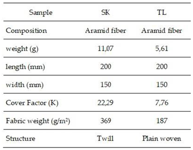 |
Table 3.
Measurements of the perforations caused by the ammunition in the composites.
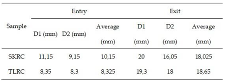 |
Table 4.
Feret index and calculation of the area and perimeter of the delamination of the composites.
Table 4.
Feret index and calculation of the area and perimeter of the delamination of the composites.
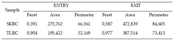 |
Table 5.
Delamination area and perimeter variation.
 |
Disclaimer/Publisher’s Note: The statements, opinions and data contained in all publications are solely those of the individual author(s) and contributor(s) and not of MDPI and/or the editor(s). MDPI and/or the editor(s) disclaim responsibility for any injury to people or property resulting from any ideas, methods, instructions or products referred to in the content. |
© 2025 by the authors. Licensee MDPI, Basel, Switzerland. This article is an open access article distributed under the terms and conditions of the Creative Commons Attribution (CC BY) license (http://creativecommons.org/licenses/by/4.0/).
Copyright: This open access article is published under a Creative Commons CC BY 4.0 license, which permit the free download, distribution, and reuse, provided that the author and preprint are cited in any reuse.


