Submitted:
24 March 2025
Posted:
24 March 2025
You are already at the latest version
Abstract
Mapping and profiling of clay resources were essential for numerous industries due to clay's unique properties and widespread availability. This study employed GPS and QGIS to map clay resources in Brgy. Bugas-Bugas, Placer, and Brgy. Cabugo, Claver, Surigao del Norte. Laboratory analysis was conducted to evaluate elemental and mineral composition, plasticity, shrinkage, water absorption, porosity, color characteristics, and flexural strength of the clay samples. Significant variations in clay properties were observed, with chemical analysis revealing higher silica content in Claver and Placer clay, indicating potential strength and lower shrinkage. Conversely, Kauswagan clay exhibited higher levels of aluminum oxide and iron oxide, suggesting increased water absorption and darker coloration after firing. XRD analysis identified montmorillonite as the main mineral found in the Claver clay sample, while the Placer clay sample from Brgy. Bugas-Bugas was identified as dickite clay, containing significant quartz and anorthite, a variety of plagioclase, indicative of a siliceous secondary clay. Plasticity tests demonstrated high plasticity for Kauswagan and moderate plasticity for Claver and Placer, while shrinkage tests indicated low drying shrinkage for Placer and high total linear shrinkage for Kauswagan. Kauswagan clay exhibited the highest water absorption rates, whereas Placer and Claver clays were suitable for tile manufacturing due to their lower water absorption rates. Porosity was highest in Kauswagan, followed by Placer. Color analysis revealed that fired Placer samples were lighter in color compared to Claver samples, with both showing a slight shift towards green and a more yellowish hue in Placer. Placer exhibited higher flexural strength compared to Kauswagan. These findings significantly contributed to understanding clay resources in the area, facilitating informed decision-making for their development and utilization of clay across a wide range of industries vital for efficient and effective resource management.
Keywords:
clay resources
; mapping
; profiling
; QGIS
; GPS
; Surigao del Norte
; XRD
; XRF
Chapter I. Introduction
1.1. Background of Study
Clay minerals are naturally occurring minerals with diverse applications in industries such as ceramics, construction, and environmental remediation [1]. Due to the growing demand for clay minerals, accurately mapping and profiling available resources is essential. Resource mapping and profiling involve gathering information about a resource’s location, quality, and quantity.
Traditionally, resource mapping and profiling of clay minerals have been conducted using various methods such as geological mapping, geochemical analysis, and geophysical surveys [2]. However, these methods can be time-consuming, expensive, and may not provide accurate results. Global Positioning System (GPS) coordinates have recently gained popularity as a resource mapping and profiling method, providing a fast and cost-effective way to collect and analyze data.
Resource mapping and profiling clay minerals using GPS coordinates is a relatively recent development in the field. Still, it has become an increasingly popular method for identifying and characterizing clay mineral deposits. GPS coordinates allow for the precise location and characterization of deposits, which is essential for efficient and effective resource management [3]. Additionally, Geographic Information System (GIS) technology can create detailed, spatial maps of the deposits and analyze the collected data. Using GPS coordinates to map clay mineral deposits in regions such as the United States, China, and Egypt has shown that using GPS coordinates is an effective method for identifying and characterizing clay mineral deposits and assessing their potential for commercial use.
This study used GPS technology and QGIS to map potential clay resources in Brgy. Bugas-Bugas, Placer and Brgy. Cabugo, Claver in Surigao del Norte. Utilizing GPS coordinates and laboratory testing, comprehensive data concerning the location and attributes of01these resources will be collected and analyzed. Subsequently, the collected data will then be used to create a detailed profile of the clay resources, including information about the type of clay, its chemical, mechanical, and physical properties.
1.2. Statement of the Problem
This study focuses on Mapping Clay Resources found in Brgy. Bugas-Bugas Placer and Brgy. Cabugo, Claver in Surigao Del Norte, particularly it seeks to answer the following questions:
- What are the types of clay minerals that can be found in the spaces of Brgy. Bugas-Bugas, Placer and Brgy.Cabugao, Claver, Surigao del Norte through XRD analysis?
- What are the chemical, physical, and mechanical properties of clay minerals found in Brgy. Bugas-Bugas, Placer and Brgy.Cabugao, Claver, Surigao del Norte?
- How can the use of GPS technology and QGIS enhance the accuracy and efficiency of clay mapping processes in Brgy. Bugas-Bugas, Placer and Brgy.Cabugao, Claver, Surigao del Norte?
1.3. Objectives of the Study
The study specifically aims to achieve the following objectives:
- To identify the type of clay minerals at Brgy. Bugas-Bugas and Cabugo, in Placer and Claver Surigao del Norte respectively through XRD analysis.
- To investigate its chemical, physical, and mechanical properties found in Brgy. Bugas-Bugas, Placer, and Brgy. Cabugo, Claver in the province of Surigao del Norte, in terms of XRF analysis, physico-mechanical properties assisted by BS Ceramic Engineering students.
- To generate the map of clay resources with their properties and profile found in Brgy. Bugas-Bugas, Placer, and Brgy. Cabugo, Claver in the province of Surigao del Norte.
1.4. Significance of the Study
Resource mapping and clay mineral profiling are crucial for various industries. Clay minerals are utilized in various industrial applications, such as ceramics, paper, and refractories. By identifying and characterizing clay resources, mapping and profiling can help to ensure a reliable supply of these minerals for these various uses. Similarly, the study of resource mapping and profiling of clay minerals is significant because it allows precise location and characterization of clay mineral deposits which is essential for efficient and effective resource management.
The mapping and profiling of clay minerals in Surigao del Norte offers important information to clay resources. This data can help mining companies locate areas with potential clay deposits that can be used as future reference. Moreover, the data and variables obtained from this study can be used to support future research related to this study.
1.5. Scope and Limitations
This part of the study includes the delimiting factor of the study, including the following:
Focus. This research was upon limited to the process of mapping of geographical position of clay resources found in Brgy. Bugas-Bugas and Cabugo, in Placer and Claver Surigao del Norte respectively, using GPS technology and QGIS. It highlighted the investigation of its chemical, physical, and mechanical properties, in inferred level of exploration classified confidence which result can be subject for continued exploration if necessary. Thus, the profiling through XRF analysis was extended in the study conducted my Ceramics Engineering students.
Time and Place. The study was conducted in Brgy. Bugas-Bugas and Cabugo, in Placer and Claver Surigao del Norte respectively in the year 2023-2024.
1.6. Conceptual Framework
The mine life cycle consists of various stages, including exploration, development, production, rehabilitation, and decommissioning. These stages encompass the entire process of mining operations from initial assessment to final closure. To ensure standardized protocols for appropriate classification and reporting standards of exploration results, mineral resources, and ore reserves, the regulatory framework established by Philippine Mineral Reporting Code (PMRC) 2020 for Reporting of Exploration is a vital component in mineral exploration [4].
Figure 1.1.
Conceptual framework of the study.
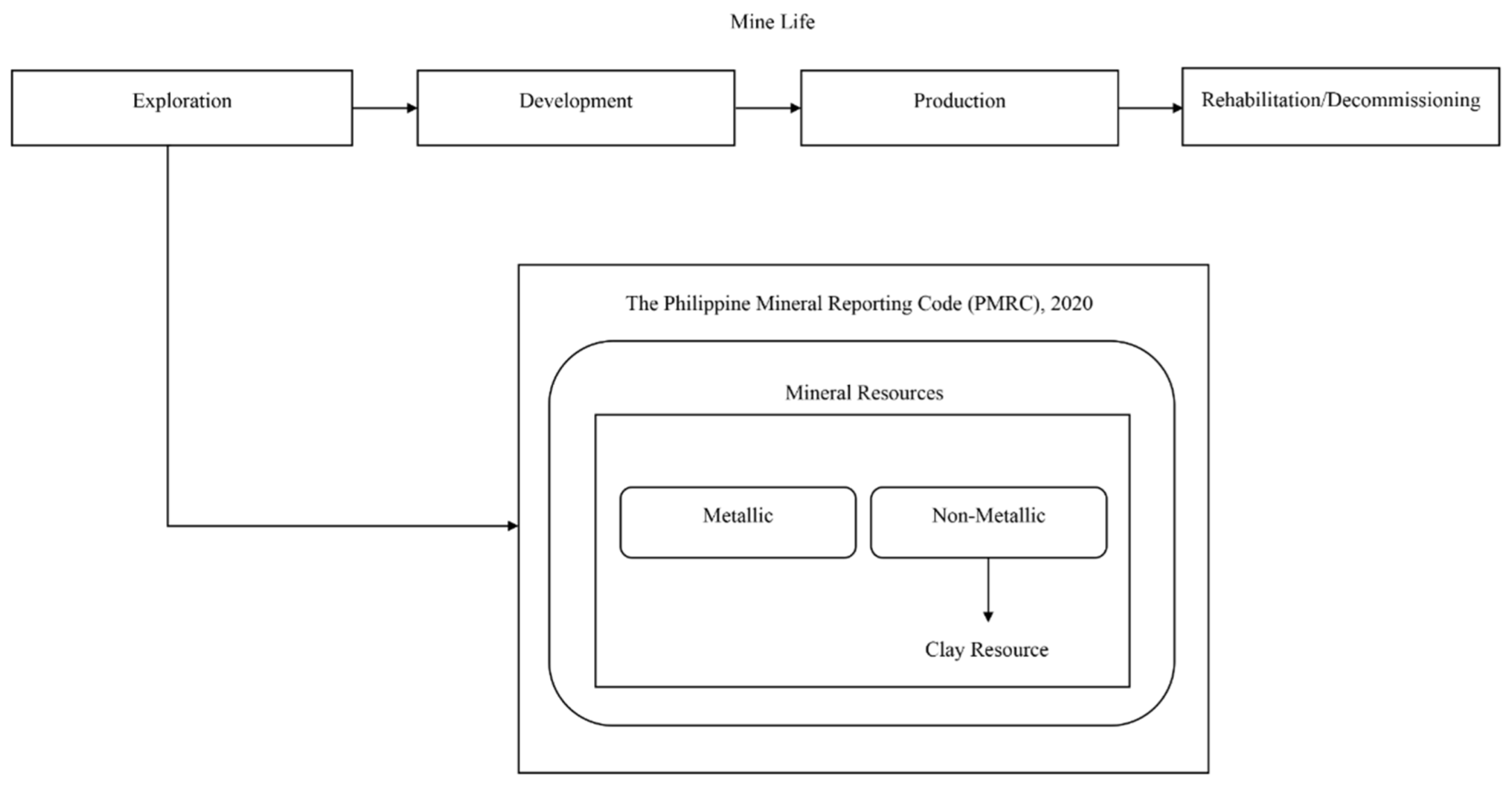
Exploration Stage is a key phase in the mine life cycle. During this stage, an exploration target may be defined which represents a statement or estimate of a potential mineral deposit. Minerals can be broadly categorized into two main groups: metallic and non-metallic, with clay falling under the category of non-metallic minerals.
Metallic Resources. Geological materials mined to produce metallic products. Non-Metallic Resources on the other hand, are natural resources extracted from the earth’s surface to its ground for commercial use and other establishing reasons.
1.7. Definition of Terms
Alluvial clay: In this study, we referred to the clay deposits formed by the deposition of sediments by flowing water found in Brgy. Bugas-Bugas and Cabugo, in Placer and Claver Surigao del Norte respectively.
Ceramics: In this study, we referred to the objects made from clay that are found in Brgy. Bugas-Bugas and Cabugo, in Placer and Claver Surigao del Norte respectively and hardened through being directed to fire and now displayed in local areas.
Clay: In this study, we referred to the soil material from Brgy. Bugas-Bugas, Placer and Brgy. Cabugo, Claver in Surigao Del Norte grounded for mapping and profiling.
Deltaic clay: In this study, we referred to the type of clay deposit that can be found in the riverbanks of Brgy. Bugas-Bugas, Placer and Brgy. Cabugo, Claver in Surigao Del Norte
Firing: In this study, we referred to the process of heating clay objects in a kiln to a specific temperature, which makes the clay hard and durable by removing moisture and causing chemical changes.
Geospatial: In this study, we referred to the combination of Brgy. Bugas-Bugas and Cabugo’s geographical data and spatial analysis, that was used to understand pattern and phenomena around the area related to the mapping and profiling process.
Geotagging: In this study, we referred to the process of adding the mapping and profiling metadata of the clay found in Brgy. Bugas-Bugas and Cabugo, in Placer and Claver Surigao del Norte respectively to the media in order to associate it with possible location.
GIS (Geographic Information System): In this study, we referred to the system used to capture, analyze, and manage geographical data of the clay around Brgy. Bugas-Bugas and Cabugo, in Placer and Claver Surigao del Norte respectively, for mapping and spatial analysis.
GPS (Global Positioning System): In this study, we referred to the satellite-based navigation system that provides the location and time information of Brgy. Bugas-Bugas and Cabugo, in Placer and Claver Surigao del Norte respectively, all the way from the outer space perspective.
Lacustrine clay: In this study, we referred to the clay deposits formed in ancient lake environments found in lakes around Brgy. Bugas-Bugas and Cabugo, in Placer and Claver Surigao del Norte respectively.
Loss on ignition: In this study, we referred to the method used to measure the organic content of clays found in Brgy. Bugas-Bugas and Cabugo, in Placer and Claver Surigao del Norte respectively by heating it and measuring the weight loss due to the combustion of organic matter.
Mapping: In this study, we referred to the process of creating visual representations of an the area around Brgy. Bugas-Bugas and Cabugo, in Placer and Claver Surigao del Norte respectively.
Modulus of rupture: In this study, we referred to the measure of the clays found in Brgy. Bugas-Bugas and Cabugo, in Placer and Claver Surigao del Norte respectively, ability to withstand bending or breaking under stress.
Outcrop: In this study, we referred to the object used for geological observations and sampling of the visible exposure of rock and soil at the surfaces around Brgy. Bugas-Bugas and Cabugo, in Placer and Claver Surigao del Norte respectively.
Plasticity: In this study, we referred to the property of clay found around Brgy. Bugas-Bugas and Cabugo, in Placer and Claver Surigao del Norte respectively after processed and while retaining its form.
Porosity: In this study, we referred to the measure of the empty spaces or voids in clays that are found in Brgy. Bugas-Bugas and Cabugo, in Placer and Claver Surigao del Norte respectively, indicating its ability to hold and transmit fluids.
Profiling: In this study, we referred to the process of gathering detailed information about Brgy. Bugas-Bugas and Cabugo, in Placer and Claver Surigao del Norte respectively involving its systematic measurements and observations.
Prospecting: In this study, we referred to the systematic search for clay deposits or valuable resources through geological surveys, sampling, and exploration around Brgy. Bugas-Bugas and Cabugo, in Placer and Claver Surigao del Norte respectively.
Shrinkage: In this study, we referred to the reduction in size or volume of the clay found in Brgy. Bugas-Bugas and Cabugo, in Placer and Claver Surigao del Norte respectively.
Spectrophotometer: In this study, we referred to the instrument used to measure the intensity of light at different wavelengths, identifying the color of the clays found in Brgy. Bugas-Bugas and Cabugo, in Placer and Claver Surigao del Norte respectively.
Topography: In this study, we referred to the physical features and characteristics of a land surface of Brgy. Bugas-Bugas and Cabugo, in Placer and Claver Surigao del Norte respectively, including its elevation, slopes, and natural or man-made features.
Weathering: In this study, we referred to the process of breaking down and altering rocks and minerals that are found in Brgy. Bugas-Bugas and Cabugo, in Placer and Claver Surigao del Norte respectively through exposure to atmospheric conditions and environmental factors.
X-ray Diffraction (XRD): In this study, we referred to the object used to analyze the crystal structure and composition of the clays found in Brgy. Bugas-Bugas and Cabugo, in Placer and Claver Surigao del Norte respectively by measuring the diffraction of X-rays.
X-ray Fluorescence (XRF): In this study, we referred to the used to determine the elemental composition of the clays found in Brgy. Bugas-Bugas and Cabugo, in Placer and Claver Surigao del Norte respectively by analyzing the fluorescent X-rays emitted when the material is exposed to high-energy X-rays.
Chapter II. Review of Related Literature
This section presents previous studies, articles, and many other information from published and uploaded journals on the internet that are related and relevant to the study at hand.
Clay: Properties and Types
Clay is a naturally occurring fine-grained soil material comprised chiefly of hydrous aluminum silicates and other minerals such as iron, magnesium, and salt. Weathering and erosion of rocks and minerals over time create it. According to Moreno-Maroto and Alonso-Azcárate [5], clay minerals offer a wide range of physical and chemical qualities that make them valuable in various applications such as construction, pottery, ceramics, and numerous industrial processes. When wet, clay can be shaped into many shapes, and when dried or fired at high temperatures, it can solidify into a durable and solid material. The unique properties of clay, such as its ability to retain water, its plasticity, and its ability to undergo changes in volume and shape without cracking, are largely based on their mineral composition and crystal structure [6] and make it a versatile and valuable material in many industries. They play a crucial role in ceramic production, and access to large quantities of high-quality clay deposits is necessary for the profitability of the ceramic manufacturing industry. Finding dependable sources of clay materials is a major challenge, requiring the implementation of simple and effective methods like GPS mapping to ensure their availability, which is a critical aspect in the competitive environment of the ceramic manufacturing industry. The availability of good quality clay is an essential factor in the competitive landscape. Furthermore, clay minerals are sediments transported and deposited in various depositional environments, spanning from land-based areas to marine environments. Clay mineral occurs in alluvial deposits, lacustrine deposits, deltaic deposits, glacial deposits, and marine deposits [7].
Alluvial clay deposits for instance, are generated by accumulating clay sediments carried by water and deposited in riverbeds, floodplains, or other low-lying places. These deposits are often made up of fine-grained clay, silt, and sand particles, with clay being the most prevalent. Clay particles are often well-sorted and have a high degree of plasticity. Alluvial clay deposits are commonly found in river valleys, deltas, and coastal plains, and are generated by the erosion and weathering of clay-rich rocks, in which Brgy. Bugas-Bugas, Placer Surigao del Norte is highly rich of because it is surrounded by riverbanks and coastal shores approximately covering most of the area. Hence, the qualities of alluvial clay deposits, such as their plasticity, mineral composition, and geotechnical characteristics, can vary depending on the source rocks, transit methods, and depositional settings around the area of source [8].
Lacustrine clay deposits are fine-grained sediments found in lake environments, forming in regions where lakes once existed or currently exist. They are low in energy, allowing fine-grained clay particles to settle over time. The composition and qualities of these deposits vary based on factors such as the source of clay minerals, the lake’s chemical environment, and sedimentation processes, which mostly found in the middle of the stratified forests located in Bugas-Bugas, Placer and Cabugao, Claver, Surigao del Norte respectively as the lakes are highly conducive with chemical because of the mining waste absorb by the environment. Hence, it is known to be abundant in nature after rainy days and mild windy days [9].
Deltaic clay deposits, similar to alluvial deposits, form near river deltas where sediment is deposited into a body of water, typically an ocean or lake. These deposits have a fine-grained composition and strong plasticity, resulting from clay particles traveling long distances and containing various minerals from different origins, which can be seen mostly in the river deltas and coastlines of Purok 1 of Brgy. Bugas-Bugas, Placer and Purok 6, of Brgy. Cabugao, Claver Surigao del Norte. More so, deltaic clay deposits are frequently connected with productive agricultural land due to the clay sedimentation processes’ high nutrient content and moisture retention qualities, wherein majority of the rice fields around the area benefit from causing sustainable growth [10].
As fine-grained clay sediments accumulate, marine clay deposits arise in oceanic and coastal environments. Clay particles settle out of the water column and build over time, resulting in these deposits. Clay minerals and varied levels of silt and organic debris are commonly found in marine clay deposits, and since Brgy. Bugas-Bugas of Place and Brgy. Cabugo of Claver Surigao del Norte are mostly surrounded with the body of waters, clay is highly adamant and rearing for production and supply. Factors such as the source of the clay minerals, wave and current activity, and the chemical makeup of the saltwater can all influence the composition and qualities of marine clay [6].
Exploration Stage: Inferred Geological Sampling
To validate the sources and properties of the clay materials, the study submerged to the exploration stage of mining life cycle particularly limited to the inferred level of geological sampling/confidence. Committee for Mineral Reserves International Reporting Standards (CRIRSCO) defines the “inferred resource” category for mineral reserves when there is a scarcity of geological evidence and sampling data [11]. This classification signifies that the resource estimation is conducted with limited information, resulting in a higher degree of uncertainty compared to more well-established categories such as “indicated” or “measured” resources [12].
Hence, assigning inferred resource classification acknowledges the broader assumptions and extrapolations used in geological interpretation and grade estimation, resulting in increased uncertainty. However, it doesn’t guarantee economic viability or extraction feasibility. Further exploration, data collection, and analysis are needed to upgrade an inferred resource to a higher category. Categorizing mineral resources based on geological evidence and sampling provides a standardized framework for transparent reporting, allowing stakeholders to evaluate resource reliability and potential value while considering uncertainty [13].
Figure 2.1.
Steps in the strategic prospecting phase of clay.
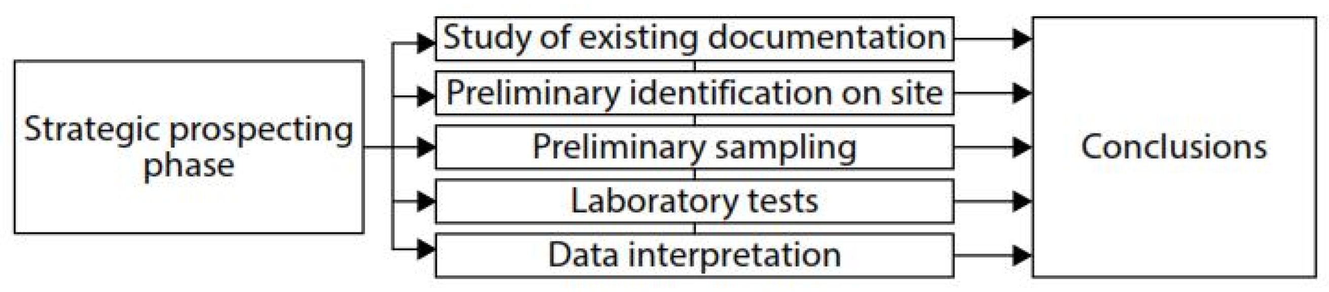
Dondi and Bertolotti (2022) suggest that an initial survey of potential areas using cost-effective prospecting techniques will be conducted to identify clay resources, based on the available research budget. It is recommended to utilize cheaper techniques during the preliminary stages, as core drilling equipment can be expensive [14].
In the pursuit of identifying clay resources, a cost-effective approach is crucial for efficient resource allocation. According to Dondi and Bertolotti, surface vegetation patterns can indicate potential resource areas since clay soils are dense, making it difficult for plant roots to penetrate and extend through them [14].
Accordingly, soil testing is an important part of soil resource management. It is critical to follow precise sampling depth requirements to acquire reliable data. Each sample taken must be a true representative of the sampled area and taken at the proper depth. Following specified sampling depth guidelines, as suggested by Chon [15], aids in ensuring that the obtained samples capture the essential characteristics and attributes of the soil profile under consideration. An inclusive table below presents suggested guidelines for the optimal sampling depths to be employed when prospecting possible clay resources [15].
As Table 2.1, pictures out, soil testing gives the variability of the soil resources that are found in an area. It highly depicts the quality of the soil formed together through natural processes laying out the earth’s surface. Its relevance to identifying clay minerals availability is mostly identified on the mineral composition, physical properties, and chemical analysis of the soil. Moreover, through the use of X-Ray Diffraction tool specific clay minerals are identified through the unique crystal structures of the soil tested [16].

Table 2.1.
Guidelines for sampling depth.
| No. | Crop | Soil Sampling Depth (cm) |
|---|---|---|
| 1 | Grasses and grasslands | 5-7 |
| 2 | Annual crops: rice groundnut, beans, vegetables, etc. (shallow-rooted crops) | 15-20 |
| 3 | Cotton, sugarcane, banana, tapioca | 20-25 |
| 4 | Perennial crops, plantations, and orchard crops | Three soil samples at 30, 60, and 90 |
Note: From “Analytical Techniques for Soil Testing,” by Tamil Nadu Agricultural University- Agritech Portal, 2013 (https://tinyurl.com/ens9wucx.).
Forthwith, the characteristics of clay for use in ceramics are often evaluated based on its plasticity, particle size, and firing properties. Other factors that can affect the quality of clay include impurities, shrinkage rate, and resistance to warping or cracking during firing due to their tendency to react to changes in moisture content [17], which can lead to foundation failure and result in damage to a building because of the uplift pressure caused by changes in the volume of clay. Additionally, clay shrinkage during drying can cause settling in buildings, stressing concrete foundations, and causing severe damage to floor slabs and rooms above them. Identifying clayey soil characteristics is crucial before construction activities, using soil classifications and other methods, as suggested by Chen [18], which are presented in Table 2.2 and Table 2.3, respectively.
Table 2.2.
Soil classification based on liquid limit and plasticity index (ASTM 4318).
| Degree of Expansion | Plasticity Index, % | Liquid Limit, % |
|---|---|---|
| Low | ||
| Medium | ||
| High | ||
| Very High |
Table 2.3.
Soil classification by shrinkage limit (ASTM 4318).
| Degree of Expansion | Shrinkage Limit |
|---|---|
| Low | |
| Medium | |
| High | |
| Very High |
Topography of Surigao del Norte: Mapping Clay Resources
In connection to the properties of clay and the effect of soil testing on its crystallization, Surigao del Norte province is abundant in clay minerals because of its soil structure. The province’s soil is primarily clay and sandy loam. The soil on the mainland is mainly loam soil (60% Anao-aon/Malimono clay loam, 20% Kabatohan clay loam, and 20% Malalag clay loam), which is permeable, moderately drained, and very appropriate for agriculture. Siargao Island’s soil comprises 80% Bolinao clay, 10% Bolinao clay steep phase, and 5% Jamoyaon clay loam. Because of the presence of mineral ores, the island of Bucas Grande is highly acidic, necessitating careful soil management. Surigao del Norte is a province in Mindanao, Philippines, bordered by the Pacific Ocean, Agusan del Norte and Surigao del Sur provinces, and the Surigao Strait. The province’s topography varies from flat to rugged, with mountain ranges like Mt. Diwata, Mt. Buhangin, and Mt. Tendido. Malimono has two main mountain ranges, Mt. Satellite and Mt. Agudo. Mt. Kabutan borders Alegria and Kitcharao in Agusan del Norte, while Mt. Legaspi is 1,170 meters above sea level. Siargao Island, located in the Philippines, has a rolling terrain with a highest point 291 meters above sea level. The island is close to the Philippine Deep, 10,700 meters below sea level, and is considered the trench’s deepest point [19].
Mapping Identified Clay Resources
GPS technology and GIS software have become increasingly popular for resource mapping and profiling in recent years. Using these tools allows for the efficient and accurate collection of data on the distribution and characteristics of resources and can improve decision-making for resource management and conservation [20]. GPS coordinates are used in resource mapping to precisely locate and mark the positions of natural resources, such as clay deposits. To locate places on the site where clay is prevalent, surveyors and geologists will utilize GPS receivers to obtain readings at various locations. The resource’s location can then be mapped using these GPS coordinates to plan extraction and utilization [21].
Additionally, according to Gao [22], the emergence of GPS technology has improved the accessibility and adaptability of spatial data collecting while also expanding the methods for integrating it with remote sensing and geographic information systems (GIS). Thus, GPS can be integrated with remote sensing, GIS, and other geospatial technologies to provide more detailed and thorough maps of clay resources.
The key advantage of using GPS for resource mapping is its ability to gather data in real-time, allowing for the rapid identification and mapping of clay deposits. GPS technology can also integrate data from multiple sources, providing a more comprehensive picture of the distribution of clay minerals in an area [21]. Another study demonstrated the effectiveness of GPS in mapping the distribution of clay minerals in a mountainous region, highlighting its ability to accurately measure elevation and location data [23].
Another area of research in using GPS for resource mapping of clay deposits has focused on integrating GPS data with other geospatial data, such as satellite imagery and aerial photos. A study demonstrated the effectiveness of integrating geospatial data for mapping clay minerals by using GPS and satellite imagery to map the distribution of kaolin deposits in a region [24].
Moreover, a study used GPS to map the extent of clay mining activities in a region, providing valuable information on the impact of mining on the environment and the local community [23]. GPS for resource mapping of clay deposits has also been applied in environmental studies, particularly in assessing the impact of mining and other resource extraction activities.
On the other hand, a study found that GPS errors can result in significant inaccuracies in mapping and profiling clay deposits, particularly in densely vegetated areas or regions with high levels of atmospheric interference [25]. One of the main disadvantages of GPS technology is its dependence on line-of-sight to the satellites, which can be disrupted by factors such as interference from buildings and trees, atmospheric conditions, and equipment malfunctions. Tables 2.4 and 2.5 highlight some of the major effects and error rates that could occur with GPS technology.
Table 2.4.
Factors affecting error rates.
| Effect | Error Values |
|---|---|
| Ionospheric effects | |
| Shift in satellite orbits | |
| Clock errors of the satellites’ clock | |
| Multipath effect | |
| Tropospheric effects | |
| Calculation and rounding errors |
Note: from “GPS SYSTEMS LITERATURE: INACCURACY FACTORS AND EFFECTIVE SOLUTIONS,” by Thin, L.N., Ting, L.Y., Husna, N.A., Husin, M.H., 2016, International Journal of Computer Networks & Communications (IJCNC) Vol.8, No.2, pp.124 (https://www.aircconline.com/ijcnc/V8N2/8216cnc11.pdf).
Table 2.5.
General factors that affect the accuracy of GPS positioning.
| GPS Satellite Signal | GPS Receiver | Usage Environment |
|---|---|---|
| Number of satellites visible | Receiver clock errors | Ionosphere and troposphere delay |
| Satellite geometry/shading | --- | Orbital errors |
| Satellite position | --- | Ephemeris errors |
| Signal delay | --- | Multi-path distortions |
| Satellite clock errors | --- | Numerical errors |
Note: from “GPS SYSTEMS LITERATURE: INACCURACY FACTORS AND EFFECTIVE SOLUTIONS,” by Thin, L.N., Ting, L.Y., Husna, N.A., Husin, M.H., 2016, International Journal of Computer Networks & Communications (IJCNC) Vol.8, No.2, pp.125 (https://www.aircconline.com/ijcnc/V8N2/8216cnc11.pdf).
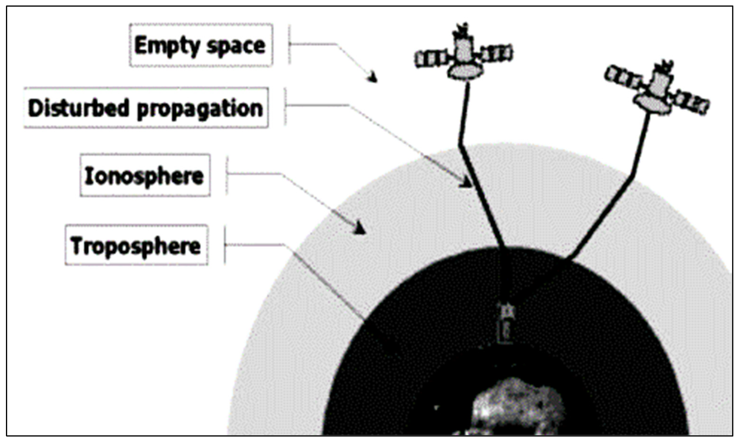
Table 2.4 provides evidence that the ionospheric effect is the primary factor contributing to errors in GPS accuracy. The sun’s ionizing force generates a considerable number of electrons and positively charged ions in the ionosphere, which is located at a height of 80-400 km. These ionized layers cause the electromagnetic waves from the GPS satellites to refract, resulting in a longer signal runtime and reduced accuracy. Figure 2.2 illustrates the ionosphere and troposphere regions.
Figure 2.2.
Ionosphere and troposphere regions. Note: from “GPS SYSTEMS LITERATURE: INACCURACY FACTORS AND EFFECTIVE SOLUTIONS,” by Thin, L.N., Ting, L.Y., Husna, N.A., Husin, M.H., 2016, International Journal of Computer Networks & Communications (IJCNC) Vol.8, No.2, pp.125 (https://www.aircconline.com/ijcnc/V8N2/8216cnc11.pdf).
A study identified three primary causes of GPS signal error: GPS satellite signal, GPS receiver, and usage environment, as shown in Table 2.5 [25].
Another drawback of GPS is its limited accuracy in extreme environments, such as those with high levels of radio frequency interference, magnetic anomalies, and high-altitude regions. A study found that GPS performance was degraded in areas with radio frequency interference, leading to reduced accuracy in mapping and profiling clay deposits [26].
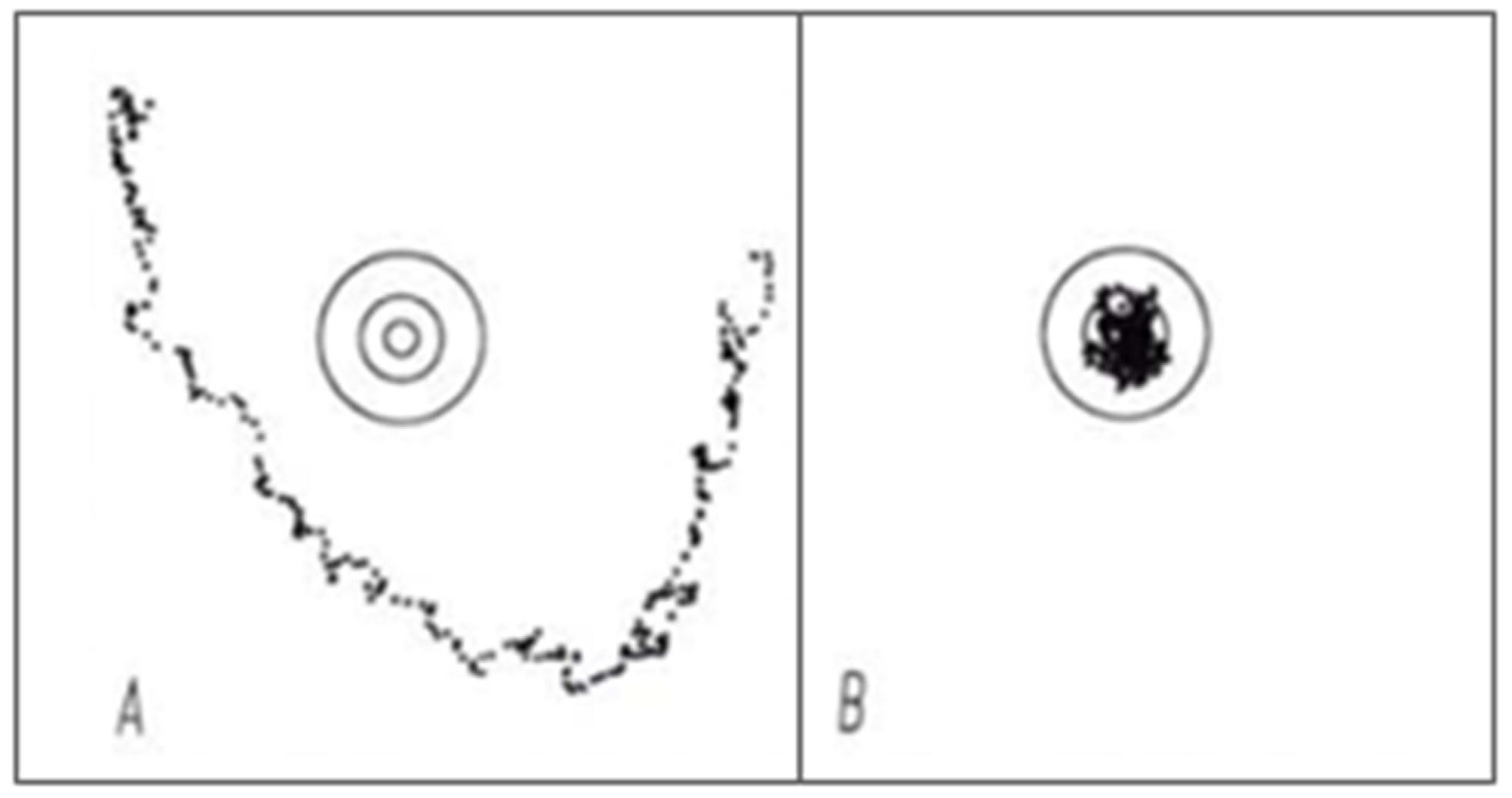
Nevertheless, these deteriorating effects can be reduced by proper mission planning and post-processing of field data, using the differential correction method in utilizing the GPS, which the researchers ought to be aware of and must understand the sources of error that can degrade the positional accuracy of the fundamental precision of the GPS-derived data [27]. Thereafter, they conducted their study: GPS for Environmental Applications: Accuracy and Precision of Locational Data, it is concluded that differential correction markedly improves the accuracy and precision of GPS data compared to without differential correction.
Figure 2.3.
(A) Without differential correction (B) After differential correction from GPS for Environmental Applications: Accuracy and precision of locational data. Note: from “GPS for Environmental Applications! Accuracy and Precision of Locational Data,” by August, P., Michaud, J., Labash, C., Smith, C., n.d., Environmental Data Center, Department of Natural Resources Science, University of Rhode Island, Kingston (https://www.asprs.org/wpcontent/uploads/pers/1994journal /jan/1994_jan_41-45.pdf).
The use of GPS coordinates provides precise location information, but it does not provide information about the type or quantity of minerals present. Other methods, such as Remote Sensing, Geophysical Surveys, Geochemical Surveys, Geologic Mapping, and Petrographic and Mineralogical Analysis, provide more comprehensive information about the mineral resources being mapped and profiled.
Remote Sensing
Remote sensing is the use of satellite imagery, aerial photography, and other remotely sensed data to gather information about the Earth’s surface. In resource mapping and profiling of minerals, remote sensing can provide valuable information about surface features associated with mineral deposits, such as geological structures, land cover, and topography [28]. The use of remote sensing and GIS can be helpful tools for primary gold favorability mapping. The integration of remote sensing data and GIS allowed for a more comprehensive and accurate assessment of the gold resources in the study area compared to traditional exploration methods. Using remote sensing and GIS can save time and reduce the cost of mineral exploration [29].
Geophysical Surveys
Geophysical surveys are used to gather data about the physical properties of the Earth’s subsurface, such as electrical conductivity, magnetic properties, and seismic velocity. This data can be used to identify subsurface geological structures and resource deposits [30]. Some of the most common geophysical methods include:
- 1.
- Gravity
Gravity is a geophysical method that measures the Earth’s gravitational field variations to detect subsurface structures and minerals [31]. It is based on the principle that the strength of the Earth’s gravitational field decreases with distance from the center of the Earth. By measuring the local gravity field, geophysicists can identify subsurface anomalies that indicate the presence of denser materials, such as mineral deposits or changes in rock density caused by subsurface structures.
- 2.
- Magnetic
Magnetic surveys measure the magnetic field of subsurface rocks and minerals to identify subsurface structures and minerals [32]. This method was based on the fact that certain rocks and minerals have a magnetic field of their own. By measuring the magnetic field strength and orientation, geophysicists can identify subsurface magnetic anomalies that indicate the presence of magnetic minerals or changes in magnetic rock properties caused by subsurface structures.
- 3.
- Electromagnetic
Electromagnetic surveys measure the conductivity of subsurface rocks and minerals using electromagnetic waves. This method is based on the principle that electromagnetic waves travel through conductive materials more efficiently than non-conductive materials [33]. By measuring the wave’s response, geophysicists can identify subsurface conductivity anomalies that indicate the presence of conductive minerals or fluids such as water, oil, or gas.
- 4.
- Seismic Surveys
Seismic surveys involve the creation of artificial or natural seismic waves, which are then measured to study the subsurface structures and properties [34]. This method is based on the principle that seismic waves will travel through different subsurface materials at different speeds. These wave speeds can be used to identify subsurface structures and estimate the physical properties of subsurface rocks and minerals. Artificial seismic waves are generated using small explosions or vibrators, while earthquakes or other natural events generate natural seismic waves. The resulting seismic waves are then measured using seismometers or other instruments to create a detailed image of the subsurface.
Geologic Mapping
Geologic mapping is the process of creating a map of the Earth’s subsurface, including information about rock types, structures, and mineral deposits. This map provides a visual representation of geological features such as rock types, stratigraphy, structures, and geological processes in an area. The information can be used to identify areas with high resource potential and to determine the quality and grade of resources [35]. Geologic mapping can be conducted using various methods, including drilling, remote sensing, and field observation.
Petrographic and Mineralogical Analysis
Petrographic and mineralogical analysis are techniques used in geology to understand the composition, texture, and structure of rocks and minerals [36]. The information can be used to identify mineral deposits, determine the quality and grade of resources, and understand the geological history of an area. Petrographic analysis can be conducted through the examination of thin sections of rock and mineral samples under a microscope, typically around 30-40 micrometers thick, which are cut and polished to reveal the internal structure and mineral composition of the rock [37]. On the other hand, mineralogical analysis involves the examination of individual mineral samples under a microscope. The process of mineralogical analysis is similar to the petrographic analysis in that it also involves using a microscope to examine the samples. However, instead of looking at rock samples, it focuses on individual mineral samples.
Chapter III
This chapter includes the methodologies used to gather and analyze data. Thus, it includes the process flow chart, site selection, sample collection and coordinates recording, sample preparation, fabrication process, characterization of samples, and map generation.
Methodology
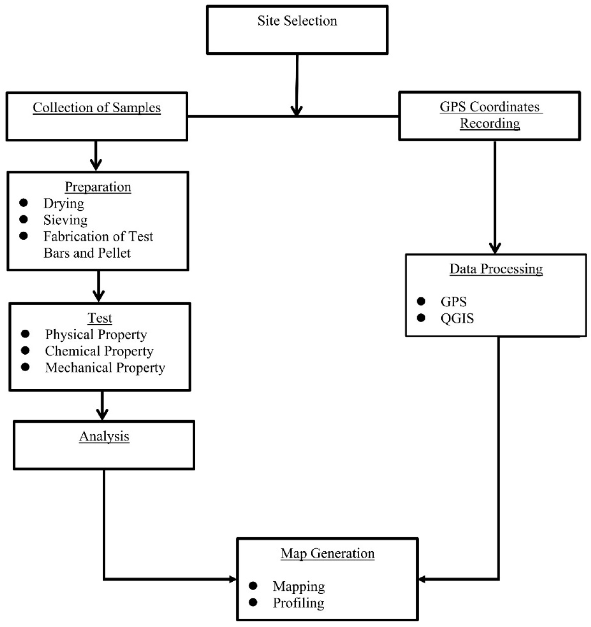
3.1. Process Flow Chart
Figure 3.1.
Overall process flow of methodology on Mapping and Profiling Clay Resources through GPS and QGIS in Brgy. Bugas-Bugas, Placer and Brgy. Cabugo, Claver, Surigao del Norte.
Figure 3.1.
Overall process flow of methodology on Mapping and Profiling Clay Resources through GPS and QGIS in Brgy. Bugas-Bugas, Placer and Brgy. Cabugo, Claver, Surigao del Norte.
3.2. Site Selection
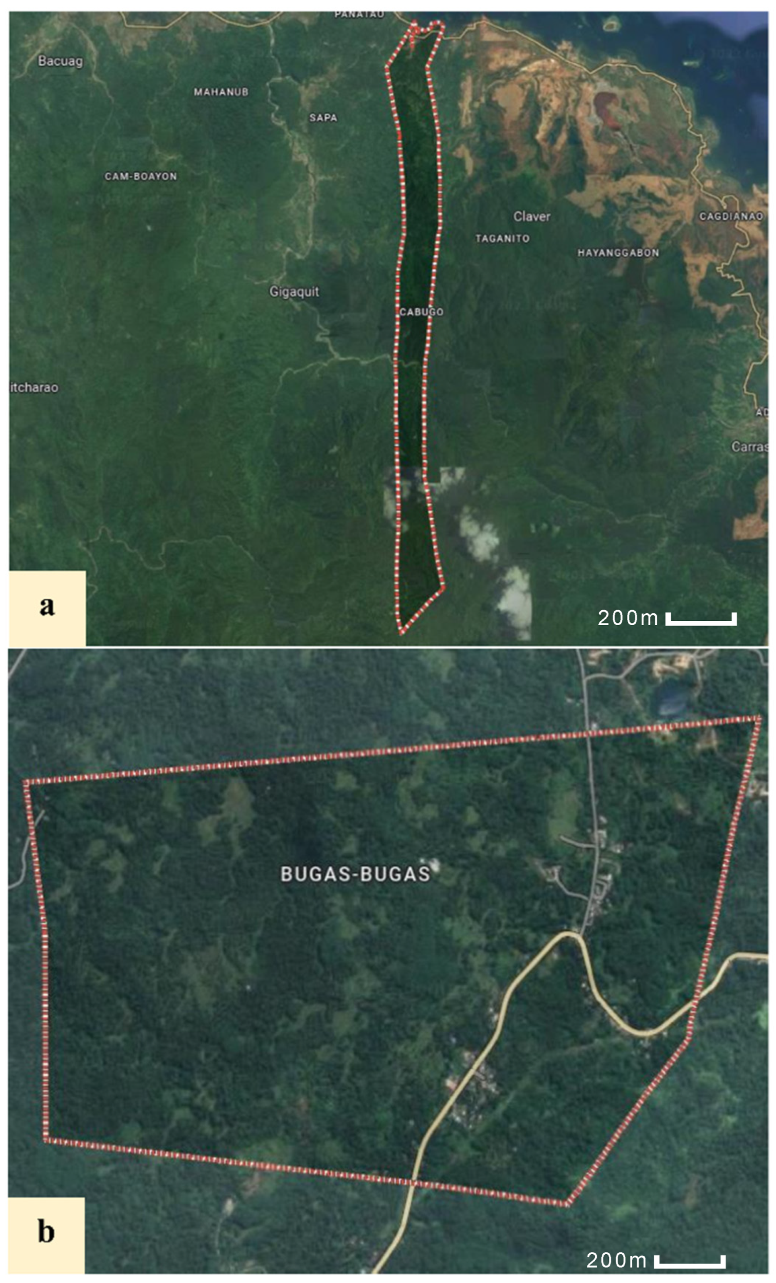
According to the official website of Surigao del Norte province [19], the municipality of Claver and Placer are bestowed with a magnificent amount of geological minerals, including clay materials. Hence, it is significantly surrounded with a large amount of water in coastal areas and riverbanks that are apprehending the areas of Brgy. Bugas-Bugas, Placer, and Brgy. Cabugo, Claver, making it the closest for site selection due to its substantial potential, including its ecosystem as clay mineral resources. Moreover, based on the data planted by the Mines and Geosciences Bureau, the aforementioned areas have significantly provided clay resources that have supplied the pottery businesses around the area but were not mapped comprehensively making it unknown to others. Consequently, the selection process also considered essential topographic criteria, such as elevation, the presence of outcrops, and vegetation patterns. More so, during site visitation, the researchers found out that the areas were characterized by sparse vegetation and fundamental environmental deposition, guided by Chon’s findings [15], which suggest that such areas may harbor potential clay resources. Thus, proving that the compact nature of clay not only hinders deep root penetration [38] but also serves as additional evidence for its presence, as it contributes to the formation of shallow topsoil conditions. Furthermore, Dondi and Bertolotti [14] have explained that clay minerals can form through the transportation and settling of sediments in different types of depositional environments, ranging from continental to marine, making the areas plausible source of clay materials.
Figure 3.2.
Satellite image of Brgy. Cabugo, Claver and Brgy. Bugas-Bugas, Placer in the Province of Surigao del Norte from Google Maps.
Figure 3.2.
Satellite image of Brgy. Cabugo, Claver and Brgy. Bugas-Bugas, Placer in the Province of Surigao del Norte from Google Maps.
3.3. Sample Collection and Coordinates Recording
Sampling and coordinate recording involved the collection of representative samples and accurately documenting their GPS coordinates. In the selected sites, namely Bugas-Bugas, Placer, and Cabugo in Claver, a composite sample was obtained. The collection followed a zigzag sampling pattern [39], including 10 subsamples evenly distributed at 10-meter intervals. Moreover, Harbitz [39] emphasized that the zigzag sampling pattern is crucial for mapping clay resource coordinates due to its systematic and efficient method of surveying and data collection. This method ensures comprehensive coverage, minimizes redundancy, and provides a structured framework for accurate resource distribution, reducing the risk of overlooking significant deposits. Each sample point coordinate was recorded using a GPS device [40].
Consequently, in order to assess the quality of the soil extracted from the surface level of the clay resources, a sampling technique was utilized which involved scraping or digging up to 60cm deep small trenches or pits to access the clay layers, which was considered to be the clay-rich horizon. Additionally, based on the standard, 500g to 1000g should be collected from each sampling point to assess the clay content of the area. But, to substantiate the need for mapping, and profiling, which includes the identification of properties content of each sample, 4 kilograms of sample material were collected. Furthermore, any debris or plant matter on the surface was removed before obtaining the sample. Thus, collected samples were then stored in separate sample bags, with each bag carefully labeled to include GPS coordinates and location. These thorough steps ensured the integrity of the samples and provided essential documentation for further analysis and interpretation [41].
3.4. Sample Preparation
After the collection of clay samples, they were sun-dried for a week to minimize moisture content, since the source of the content is surrounded with water. After drying, each clay sample was crushed and pulverized. Subsequently, the samples were sieved through a 60-mesh sieve to obtain a uniform particle size. Each clay sample was weighed to obtain a specific quantity of 1 kilogram, which was then mixed with a 10% water solution having 4% Carboxymethyl cellulose (CMC) content. The resulting mixture was left to age for 24 hours, allowing for the development of optimal binding properties and ensuring the clay samples were well-prepared for subsequent analysis or usage.
3.5. Fabrication Process
3.5.1. Test Bar Making
The test bars (refer to Appendix B.2.1) preparation involved using the aged clay sample. During the fabrication process of individual test bars, a standardized quantity of 100 grams of clay was carefully measured. To ensure optimal compaction, a hydraulic press was employed. A specifically designed mold with dimensions of 100 mm x 36.5 mm was used. A controlled force of 40 N was applied, effectively pressing the clay sample within the mold.
3.5.2. Pellet Making
Pellets (refer to Appendix B.2.2) were made using a 4-gram sample of aged clay. After preparing the clay sample, it was placed into a pelletizer to produce a pellet. All in all, there were 15 pellets made which will be subjected to drying and firing process enough to attest its durability as ceramic materials.
3.5.3. Drying and Firing
The test bars and pellet samples were dried in an oven at 110°C for 6 hours (refer to Appendix B.2.3). After drying, their dimensions were measured to determine the drying shrinkage. Then, the dried samples were fired at 850°C as post-firing, wherein the dimensions were measured again to determine the firing shrinkage and assess any changes that had occurred with its weight and physical properties ensuring if it was strong enough to use for ceramic manufacturing purposes. Thus, fired shrinking and absorption are reliable measures of bodily maturation. Apparently, from the 15 pellets and test bars made only 3 of every type of clay (Kauswagan, Placer, and Claver) were constructed for the rest were cracked out [42].
3.6. Characterization of Samples
In conducting the chemical analysis, the Kauswagan clay sample is employed as a control sample to assess and compare the Claver and Placer samples. Moreover, Kauswagan clay, with a mineral composition of kaolinite, montmorillonite, and illite, is suitable for various uses due to its light beige to reddish-brown hue. Its flexibility depends on particle size and mineral makeup, making it suitable for ceramics. By utilizing the Kauswagan clay sample as a reference, the characteristics, properties, and behavior of the Claver and Placer samples can be evaluated in correlation with it. This chemical analysis allows the identification of any differences or variations observed among the samples, enabling a comprehensive understanding of their composition and behavior [43].
3.6.1. Chemical Analyses
3.6.1.1. X-Ray Fluorescence Analysis
X-ray Fluorescence analysis is a technique used to analyze the chemical composition of the minerals such as clays. Furthermore, it is used as a tool for various areas for its prompt elemental analysis non-destructively [44].
The samples were sieved through a 325-mesh. Subsequently, the samples were oven-dried at a temperature of 110°C for two hours, until the moisture content of the samples was reduced to less than 1 percent. The samples were then sent to the House Technology Industries Pte Ltd. for analysis.
3.6.1.2. X-Ray Diffraction Analysis
X-ray diffraction analysis is an intensive nondestructive method for characterizing the crystallographic structure of materials by looking through the diffraction pattern produced during the interaction of X-rays to the crystalline structure of the materials. It contains information on structures, phases, preferred crystal orientations (texture), and other structural factors including average grain size, crystallinity, strain, and crystal defects [45].
The samples were sieved through a 200-mesh. Subsequently, the samples were oven-dried at a temperature of 110°C for two hours until the moisture content of the samples was reduced to less than 1 percent. The samples were then sent to the laboratory of Mines and Geosciences Bureau-Region 10 office for analysis.
3.6.2. Physical Property Testing
3.6.2.1. Plasticity Test
For sample preparation, water was added to the sample powder that had passed through a 60-mesh, comprising approximately 50 to 60 percent of the mixture. The mixture was thoroughly mixed and kneaded to create a well-formulated body. Subsequently, the plastic mass was sliced in half until the surface appeared smooth. Finally, the formulated body was placed inside a plastic bag and aged for a day to allow for proper conditioning.
Next, the sample will be directed to liquid limit test, a test wherein the moisture content of the soil from its plastic state to liquid state is measured. The test was used to assess the behavior of the soil being exposed to liquid materials [46]. The test involved compressing an aged soil sample in a liquid limit apparatus, cutting a groove, and recording the number of drops needed for the soil pat to contact. A sample was then placed in a moisture can, weighed, and dried in an oven for 16 hours. The result was calculated using the liquid limit formula stated below.
where:
N1 = no. of blows (lower value)
N2 = no. of blows (higher value)
MC1= initial moisture content
MC2= final moisture content
MC25= moisture content on 25mm groove distance
For the plastic limit test, the remaining 1/4 of the original soil sample was taken and distilled water was added until the soil reached a consistency where it could be rolled without sticking to the hands. The soil was then shaped into an ellipsoidal mass and rolled between the palm or fingers and a glass plate with sufficient pressure and about 90 strokes per minute, aiming to create a thread with a uniform diameter of 3.2 mm (1/8 in.) within two minutes. Once the thread reached the desired diameter, it was broken into pieces, kneaded, and re-rolled into ellipsoidal masses. This process of alternate rolling, gathering, kneading, and re-rolling was repeated until the thread crumbled under the rolling pressure and could no longer be formed into a 3.2 mm diameter thread.
The portions of the crumbled thread were gathered together and placed into a moisture can, which was then covered. If the can did not contain at least 6 grams of soil, additional soil from the next trial was added to the can. The moisture can, along with the soil, was immediately weighed, and the mass was recorded. The lid was removed, and the can was placed in an oven for a minimum of 16 hours for drying. After oven drying, the samples were weighed again. Calculate the plastic limit using the formula below [47].
3.6.2.2. Shrinkage Test
To attest the moisture content of a soil clay, shrinkage test was used at which proven that further loss of moisture ceases to induce volume reduction [48]. The dimensions of the test bars and pellets were measured before oven drying with the initial average length of 101.2mm calculated using the equation below. The test bars and pellet samples were then placed in an oven and dried at 110°C for 6 hours it diminished by around 0.6mm leaving samples with an average length of 100.6mm. Subsequently, the dried samples were fired at 850°C. After firing, the dimensions were measured once again to evaluate any changes that occurred, with an average length of 95.8mm. Thus, the total shrinkage was then calculated using the provided formula below [42].
3.6.2.3. Loss on Ignition
After the drying and the firing session, to assess the organic matter content of every sample, the researchers used the loss on ignition (LOI) test. It involved heating a sample of the clay in a kiln to a high temperature, typically around 850°C, in a furnace to burn off any organic matter. The weight loss observed during this heating process represented the amount of organic material present in the clay. The LOI was calculated using the formula below [49].
3.6.2.4. Water Absorption
The water absorption test was initiated by weighing the test bars and pellets after they had been fired before testing, this was to measure the water content of the soil and its behavior in different moisturized conditions [50]. The samples were subsequently soaked in distilled water until they reached boiling point. Once boiling, the test pieces were completely immersed in the boiling water for 5 hours. Following the immersion period, the samples were allowed to cool for 24 hours while remaining submerged in water. Once cooled, any water droplets present on each sample were lightly wiped off using a clean, dry cloth. The samples were then reweighed. To determine the percent water absorption, the difference in weight before and after the test was calculated and expressed as a percentage using the formula below and by a digital scale to determine the weight of both dry and wet samples [51].
where:
W-Wet weight of sample
D-Dry Weight of the sample
3.6.2.5. Apparent Porosity
After the wet/soaked weight of the samples was determined in the water absorption test, each sample was hung using a wire and suspended in a beaker with water, ensuring that the sample did not touch the bottom of the beaker (following Archimedes’ Principle). The weights of the suspended samples, known as suspended weights (S), were recorded as the difference of the initial weight of the sample and the weight of the sample in water. Moreover, the percent apparent porosity of each sample was then computed using equation 3.8, wherein the weight of the dry sample will be subtracted from the weight of the wet sample and be divided with the difference of the wet weight sample and suspended sample. Suspended weight on the other hand is computed as the difference between the initial weight of the sample and the weight of the sample in water [50].
where:
W—Wet Weight of the sample
D—Dry Weight of the sample
S—Suspended Weight of the Sample
3.6.2.6. Color
Color tests were conducted to assess the color physical property of clay. The procedure involved visually observing and recording the color of the clay sample using a spectrophotometer. To calculate the color difference of the samples, the following formula were used [52].
where:
∆L*: Difference in lightness. Positive means lighter, negative means darker.
∆a*: Difference in red-green axis. Positive means more red, negative means more green.
∆b*: Difference in yellow-blue axis. Positive means more yellow, negative means more blue.
∆E*: Total color difference value. Combines ∆L*, ∆a*, and ∆b* into a single value, quantifying overall difference between colors.
3.6.3. Mechanical Property Testing
3.6.3.1. Modulus of Rupture
After series of stages done testing the physical property of the sample, a modulus of rupture (MOR) test is done to make sure that the sample will endure and last bending conditions. For this reason, the test bar sample was then placed on two-point supports at a specified distance to set up the three-point bending configuration. A point load was applied to the sample using a universal testing machine, and the load at which the sample failed was recorded resulting to maximum force or the load at failure (F), while the length (L), width (b), and thickness (d) were recorded using a caliper directly measuring the samples [53]. Thus, to calculate the MOR the formula (Equation 3.13) was used [54].
where:
F = Load at Failure: The maximum load sustained by the specimen before rupture expressed in unit force or newton.
L = Length: The length of the specimen in millimeter unit.
b = Width: The width of the specimen in millimeter unit.
d = Thickness: The depth or thickness of the specimen in millimeter unit.
3.7. Map Generation
3.7.1. Mapping and Profiling
The map generation process began by geotagging the location of 10 clay samples per study area using a GPS device-Garmin Oregon 550 model which has 3.2-megapixel digital camera, barometric altimeter, 3-axis electronic compass and microSD. Through the utilization of QGIS, the GPS coordinates were imported and translated into a point layer, representing the sample locations. This point layer formed the foundation for the creation of the spatial map. QGIS also facilitated the integration of additional data related to the clay resources, such as their type and various properties like chemical, mechanical, and physical characteristics. The boundary was accurately identified by creating a 5-meter buffer around the sample pattern. The collected samples’ locations were then plotted, and the resulting data was utilized to create a spatial map of the clay resources using QGIS. Utilizing the collected data, a spatial map of the clay resources was generated using QGIS software. Overall, the integration of advanced technology, systematic sampling methodology, and spatial analysis techniques contributed to a comprehensive understanding of clay resource distribution around the areas which will help in navigating the resources easier [20].
Chapter IV. Results and Discussion
This chapter presented the result and analysis of study. The results and their corresponding discussions were presented according to the statement of the problem in Chapter 1.
4.1. Chemical Analysis
4.1.1. XRF Analysis
Table 4.1 presents the XRF analysis of Placer and Claver samples, and Kauswagan clay sample. The main components found were SiO2, Al2O3 followed by Fe2O3, K2O, TiO2, CaO, and MnO.
Table 4.1.
Average oxide analysis of the clay bars gathered from locations identified and fabricated through XRF analysis.
Table 4.1.
Average oxide analysis of the clay bars gathered from locations identified and fabricated through XRF analysis.
| COMPONENT | Oxide Content (weight %) | ||
|---|---|---|---|
| Kauswagan (Control) |
Placer | Claver | |
| SiO2 | 40.300 | 67.500 | 54.300 |
| Al2O3 | 29.150 | 22.400 | 25.800 |
| Fe2O3 | 25.750 | 4.8600 | 15.755 |
| CaO | 0.5085 | 1.6850 | 0.9885 |
| MgO | ND | ND | ND |
| Na2O | ND | ND | ND |
| K2O | ND | 1.6400 | 0.7890 |
| SO3 | 0.08215 | 0.4850 | 0.1620 |
| TiO2 | 3.2000 | 0.8310 | 1.4450 |
| BaO | 0.2085 | 0.0223 | 0.0204 |
| MnO | ND | 0.0938 | 0.1530 |
| P2O5 | ND | ND | ND |
| Cr2O3 | 0.1665 | 0.0329 | 0.0327 |
| V2O5 | 0.1810 | 0.0818 | 0.1265 |
ND = Not detected.
According to the results, both the Claver and Placer samples contain higher proportions of silica (SiO2) compared to Kauswagan clay. The Claver sample predominantly consists of silica at a significant proportion of 54.3%, while the Placer sample has an even higher silica content of 67.5%. In contrast, Kauswagan clay has a lower silica content of 40.3%. A higher silica content in clay indicates increased strength. Silica plays a role in reducing drying and firing shrinkage, while also imparting stiffness to clay products [55]. In this case, both the Claver and Placer samples, when compared to Kauswagan clay, demonstrate higher silica content which, theoretically, indicates higher strength and lower drying and firing shrinkage.
Furthermore, Kauswagan clay exhibits a slightly higher aluminum oxide content of 29.15% compared to the Claver (25.8%) and Placer samples. As per the research conducted by Cáceres et al. [56], theoretically, it can be inferred that Kauswagan clay exhibits higher water absorption and enhanced plasticity compared to Placer and Claver samples.
In addition, Kauswagan clay demonstrated a significantly higher iron oxide (Fe2O3) content of 25.75% compared to the iron oxide content of the Claver and Placer samples, which were 15.755% and 4.68%, respectively. Theoretical evidence suggests that both the Claver and Placer samples exhibit lighter coloration in comparison to Kauswagan clay. This observation aligns with the theory proposed by Alam [57], indicating that Kauswagan clay undergoes a transformation from red to a darker hue during the firing process.
Moreover, other alkali components such as potassium oxide (K2O), titanium oxide (TiO2), manganese oxide (MnO), and calcium oxide (CaO) were found to be present in low concentrations in all three samples. Based on theoretical evidence, this indicates that high levels of densification will not be possible at temperatures below 1000°C, as they are fluxing agents [58].
4.1.2. XRD Analysis
The results obtained from the analysis of the diffractogram of the Claver sample showed the presence of minerals. Based on the interpreted analysis conducted, the mineral composition includes montmorillonite (peaks 1, 5, 8, and 9), halloysite (peaks 4 and 6), and beta quartz (peak 7). The montmorillonite detected around the 2θ angle values of 6.097°, 25.539°, 45.096° and 54.234°. Moreover, in the minor phases, halloysite is detected around 2θ angle values of 20.153° and 35.188°, while beta-quartz is detected around 38.496°. This indicates that in the diffractogram, montmorillonite is the major phase present in the sample. And for the unidentified peaks, further verification will be conducted to have an accurate identification of the peaks. Furthermore, the summary of these identified peaks is presented in Table 4.2. On the other hand, the result from the analysis conducted by the Lands Geological Survey Division, Mines and Geosciences Bureau, Claver sample is identified as montmorillonite ((Na,Ca)0.33(Al,Mg)2(Si4O10)(OH)2·nH2O) (see Appendix E).
Figure 4.1.
X-ray diffraction patterns of the Claver sample.
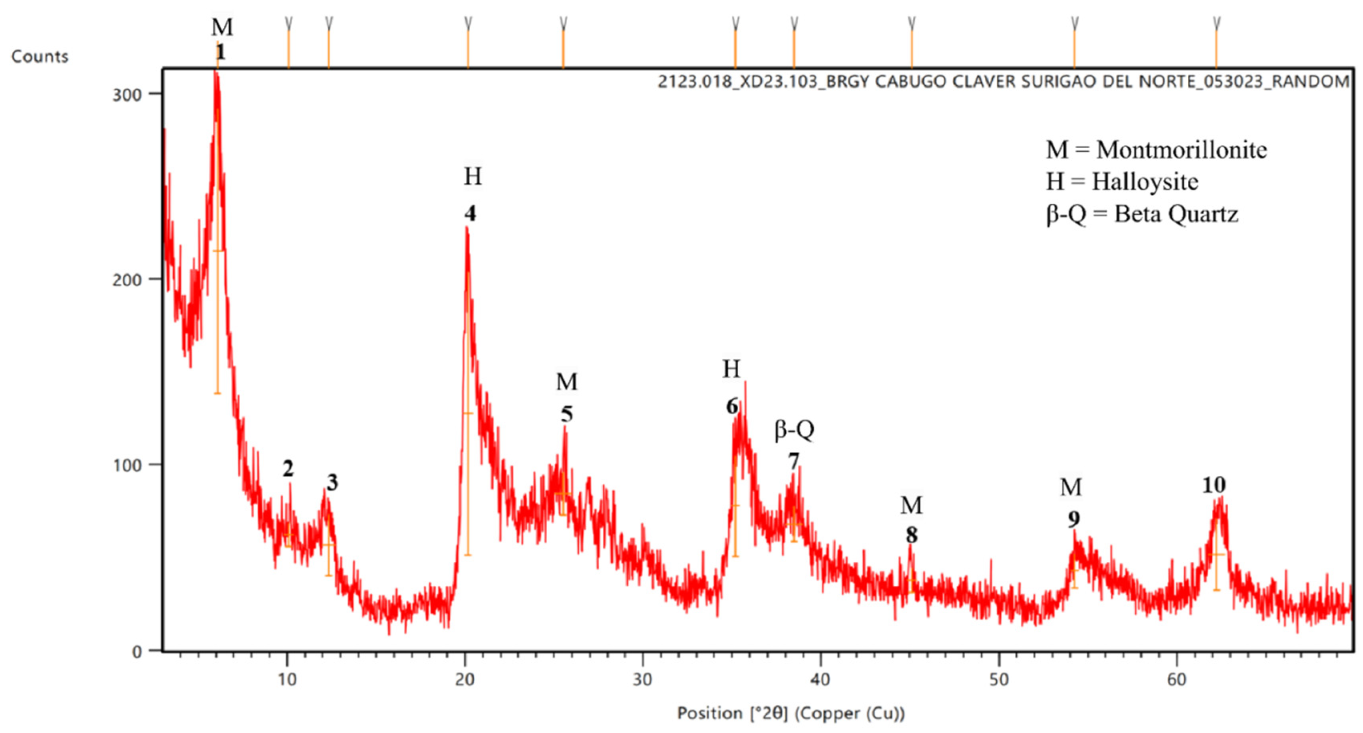
Table 4.2.
XRD results of the Claver sample showing the mineral composition in weight percent.
| Minerals Identified | Mineral Abundance (%) |
|---|---|
| Montmorillonite | 40 |
| Halloysite | 20 |
| Quartz (β) | 10 |
Table 4.2 illustrates the mineral composition of the X-ray diffraction results of the Claver sample with montmorillonite as the predominant mineral. As depicted in the table, the Claver sample was composed of 40% montmorillonite, 20% halloysite and 10% beta-quartz. The presented data in the table depicts the dominance of montmorillonite within the Claver sample. This mineral holds the highest proportion, indicating its prevalence and significance in the sample. Additionally, halloysite contributes a notable portion while beta-quartz, although present in a smaller percentage, still contributes to the overall mineral composition of the Claver sample.
The diffractogram obtained from the x-ray diffraction (XRD) analysis of Placer sample was identified and indexed, revealing a complex, mineralogical composition. The analysis prominently highlights a high content of quartz, along with significant amounts of secondary minerals. The key minerals identified in the sample include alpha quartz, dickite, anorthite, and both alpha and beta tridymite, as illustrated in Figure 4.2.
Figure 4.2.
X-ray diffraction patterns of Placer sample.
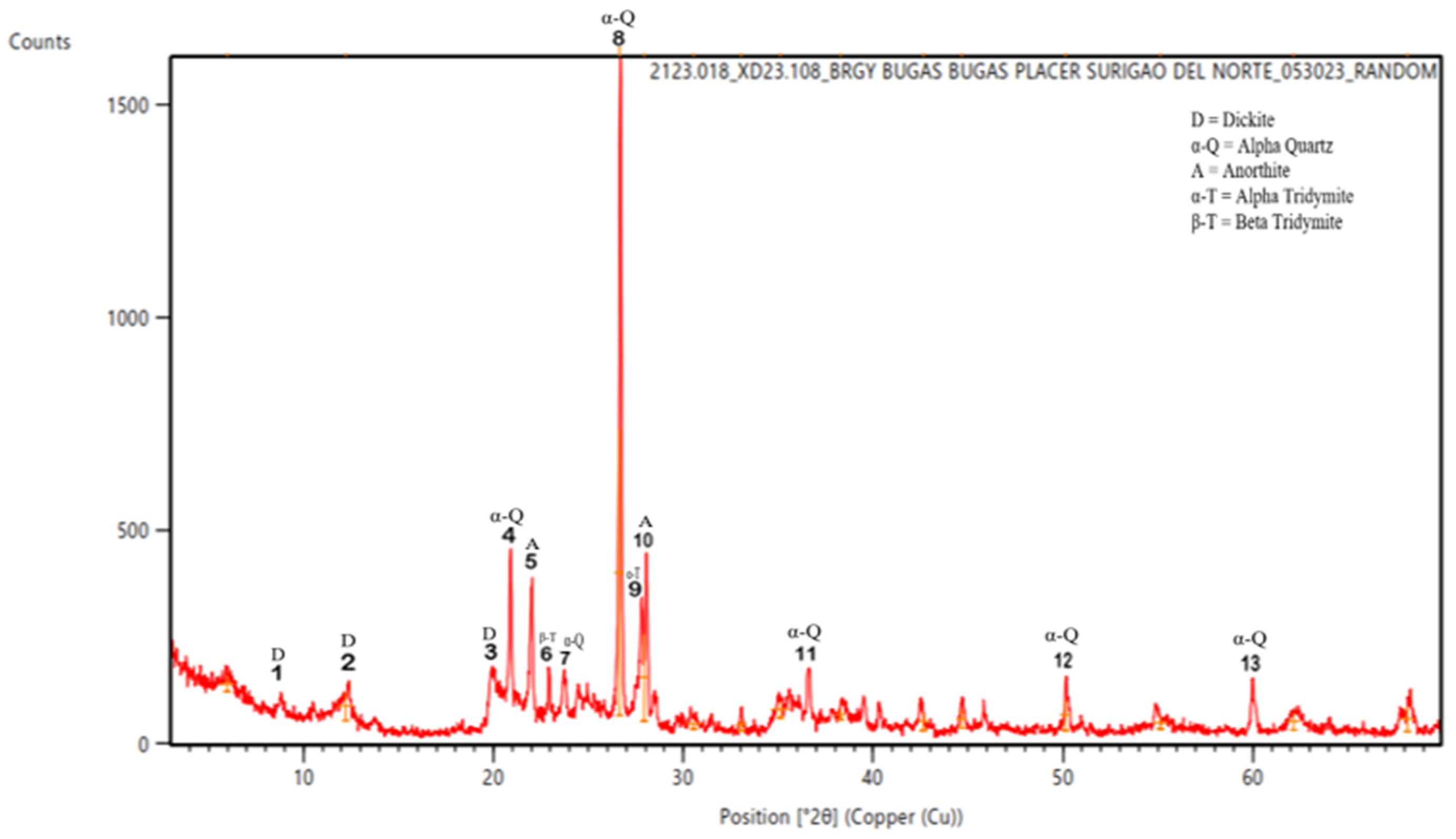
The X-ray diffraction analysis graph of the Placer sample was shown in Figure 4.2, where it revealed the presence of various minerals. According to the interpreted analysis conducted, the mineral composition included alpha (peaks 4, 7, 8, 11, 12 and 13) phases of alpha quartz. Additionally, dickite (peaks 1,2, and 3), anorthite (peaks 5 and 10), alpha tridymite (peak 9), and beta tridymite (peak 6). The diffractogram indicated that alpha quartz was the major phase in the sample and was detected at 2θ angles of 26.663°, 20.893°, 23.739°, 36.636°, 50.146° and 60.023°. Additionally, dickite was detected at 2θ angles of 8.276°, 12.241° and 19.668°, while anorthite was detected at 2θ angles of 22.066° and 27.958°. Furthermore, alpha tridymite is found at 2θ angle of 27.801° and beta tridymite at 22. 921°. The findings of the analysis are summarized in Table 4.3, providing valuable insights into the mineral composition of the Placer Sample.
Table 4.3.
XRD results of the Placer sample showing the mineral composition in weight percent.
| Minerals Identified | Mineral Abundance (%) |
|---|---|
| Quartz (α) | 38.46% |
| Dickite | 30.77% |
| Anorthite | 15.38% |
| Tridymite (α) | 7.69% |
| Tridymite (β) | 7.69% |
The significant presence of alpha quartz (38.46%) combined with the detected presence of dickite (30.77%), a secondary clay mineral, indicates that the Placer sample is characterized as a siliceous secondary clay (see Table 4.3). The abundance of quartz suggests a primary source rich silica, while the presence of dickite implies secondary processes (hydrothermal alteration or weathering), common in the formation of clay minerals.
Moreover, the analysis conducted by the Lands Geological Survey Divisions, Mines and Geosciences Bureau also identified the primary components of the Placer Sample as quartz (SiO2) and plagioclase ((Na,Ca)Al(Si,Al)Si2O8). This corroborates the findings of the XRD analysis performed through detailed indexing. The presence of plagioclase, specifically identified as anorthite (through manual indexing), further supports the classification of the sample as dickite, a siliceous secondary clay.
4.2. Physical Property Testing
4.2.1. Plasticity Test
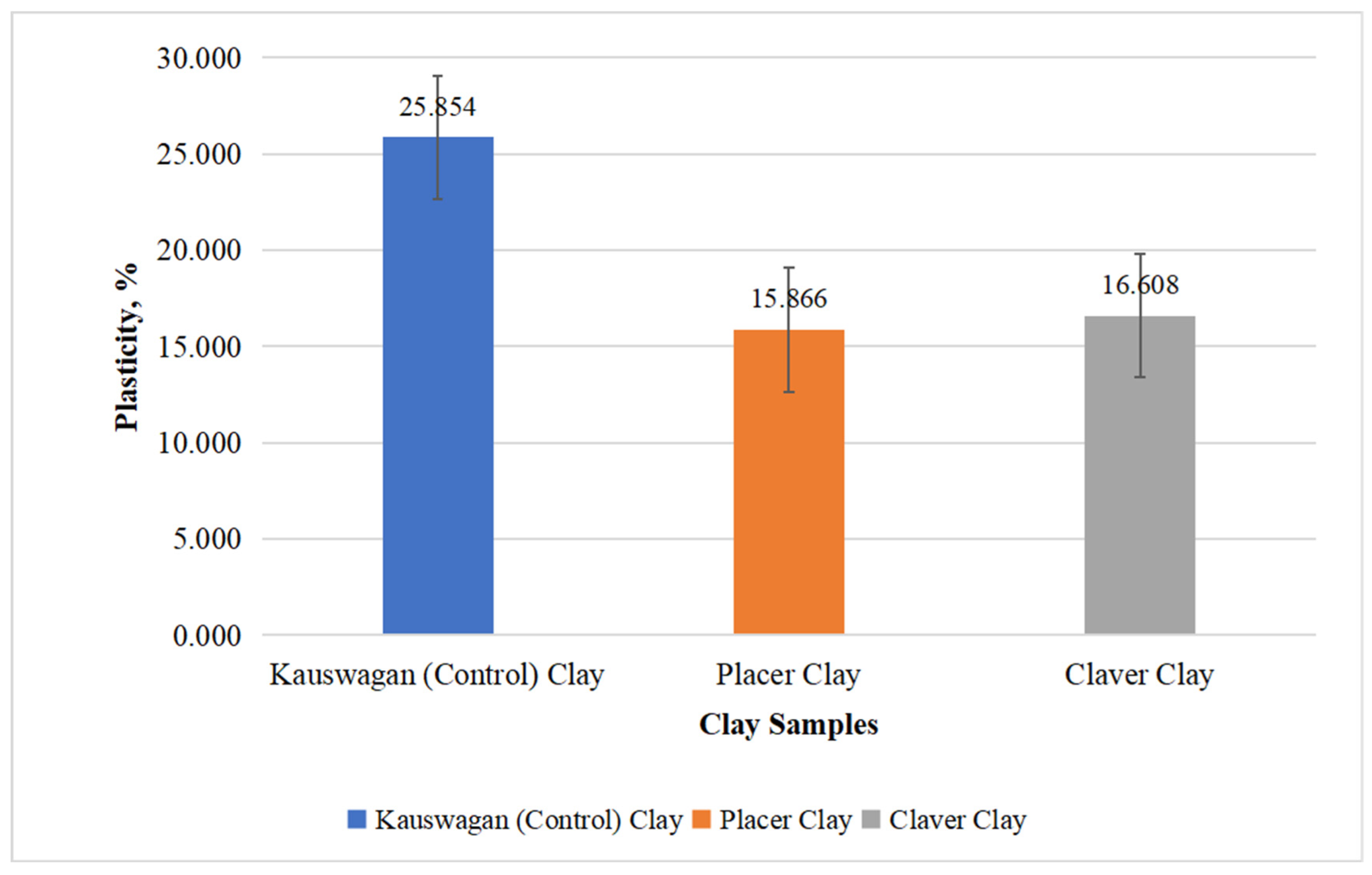
Figure 4.3 illustrated the plasticity index values of three clay samples: Kauswagan, Placer, and Claver. The plasticity index values obtained from the graph were as follows: Kauswagan - 25.854%, Placer - 15.866%, and Claver - 16.608%. According to the research conducted by Chen [18] in the book “Foundations on Expansive Soils” (see Table 2.1), the plasticity classifications of these clay samples could be determined. Hence, based on theoretical foundations, it could be deduced that Kauswagan clay showcased a high level of plasticity, implying its capacity for substantial deformation under stress. Conversely, both the Claver and Placer samples demonstrated a moderate degree of plasticity. The plasticity limit parameter, PL, was higher than 15%, suggesting potential applications in the red ceramic area. PL values between 17.2% and 32% allowed for ceramic processing and/or conforming via extrusion according to Teixeira et al. [59]. Based on PL values, the Placer and Claver samples with PL values of 30.4% and 56.9%, respectively, had potential for producing ceramic tiles, pottery, and bricks.
Figure 4.3.
Plasticity index of clay samples from identified location after undergoing the fabrication process.
Figure 4.3.
Plasticity index of clay samples from identified location after undergoing the fabrication process.
4.2.2. Shrinkage Test
The figure presented the average drying, firing, and total linear shrinkage values for three samples: Kauswagan, Placer, and Claver fired at 850°C and dried at 110°C. As observed in the graph, the drying shrinkage of the Placer test bar had the lowest shrinkage with the values of 0.198%, while the Claver test bar samples had the highest drying shrinkage of 1.491%. This indicated that there was an inconsistency in the drying shrinkage results of the samples due to the different pressure applied in the test bar. Hence, this indication was also true in the firing shrinkage of the samples, in which the results had different trends. As for the total linear shrinkage of the three samples, Kauswagan displayed a value of 5.329%, Placer had a value of 0.712%, and Claver had a value of 5.953%. This result further implied that Kauswagan had significantly shrunk compared to Placer due to its low silica (SiO2) content (see Table 4.1), while Claver had the largest shrinkage among the samples due to its high organic content. Moreover, the linear shrinkage of both Kauswagan and Claver shown in the figure was found to be within the standard range for fireclay (4-10%), which could indicate that they could be used in producing firebricks [60].
Figure 4.4.
Average percent shrinkage of test bars samples from three different variety dried at 110°C and fired at 850°C subsequently.
Figure 4.4.
Average percent shrinkage of test bars samples from three different variety dried at 110°C and fired at 850°C subsequently.
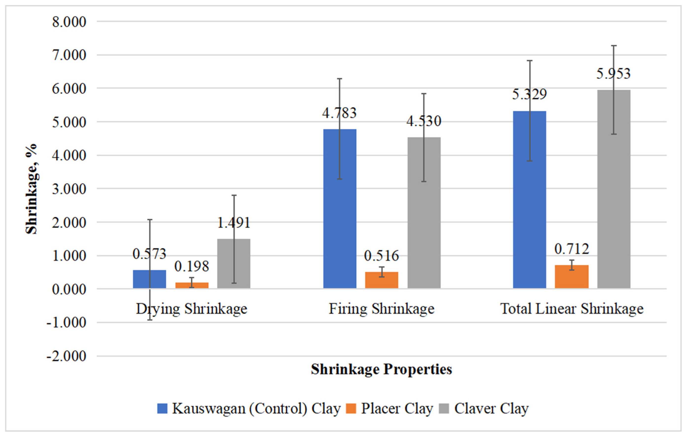
Figure 4.5.
Average percent shrinkage of pellet bars samples from three different variety dried at 110°C and fired at 850°C subsequently.
Figure 4.5.
Average percent shrinkage of pellet bars samples from three different variety dried at 110°C and fired at 850°C subsequently.
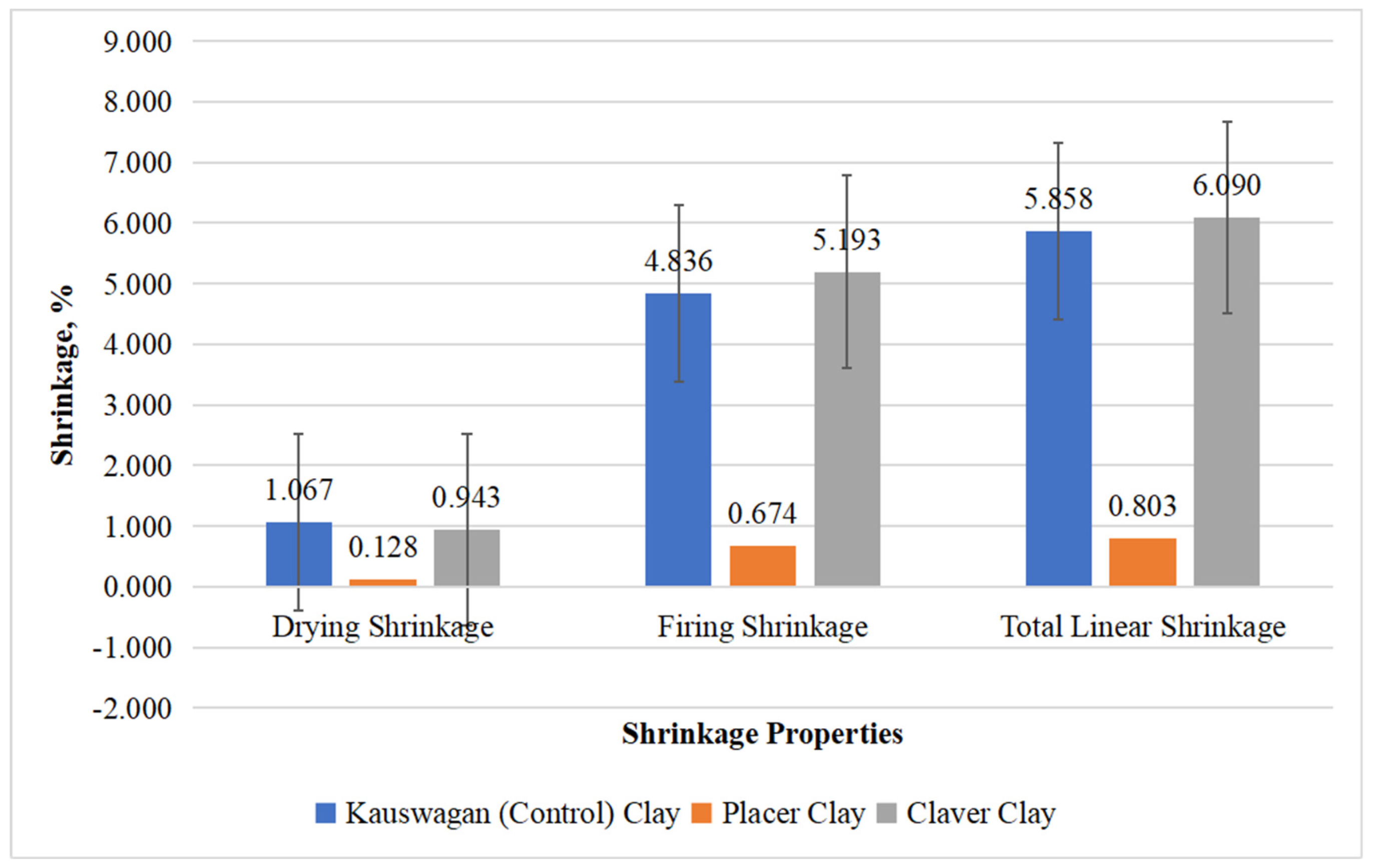
The figure stated the subsequent shrinkage percentage of the pellet bars of the evaluated samples the Kauswagan clay, Claver clay, and Placer clay after being dried in a 110°C and fired under 850°C oven temperature. After being dried up, the Kauswagan clay seemed to be more dry, accumulating 1.06 of total shrinkage percentage followed by Claver (0.943%) and Placer (0.128%) clays respectively. Furthermore, after being fired under 850°C, the Claver clay accumulated the highest shrinkage percentage as to 5.193% in total because of its organic content, followed by Kauswagan clay (4.836%), and Placer clay (0.674%) respectively. Thus, leaving the linear shrinkage of Claver clay and Kauswagan worthy to be used on ceramic manufacturing purposes.
4.2.3. Weight Loss on Ignition
Figure 4.6. drawn out the average weight ignition loss of the test bars samples from three different varieties of clays namely: Kauswagan, Placer, and Claver clays respectively. Which have noted that clay resources found in Brgy. Bugas-Bugas, Placer had the lowest weight loss which proved that it had the lowest organic compound necessary for water absorption. While the clays in Brgy. Cabugao, Claver had the highest weight loss recorded, which can be concluded that the clays are sufficient with organic content leading to color variations, and primary source of clay for pottery use [61].
Figure 4.6.
Average percent weight loss of test bar from three varieties of clays fired at 850°C after undergoing the shrinkage test.
Figure 4.6.
Average percent weight loss of test bar from three varieties of clays fired at 850°C after undergoing the shrinkage test.
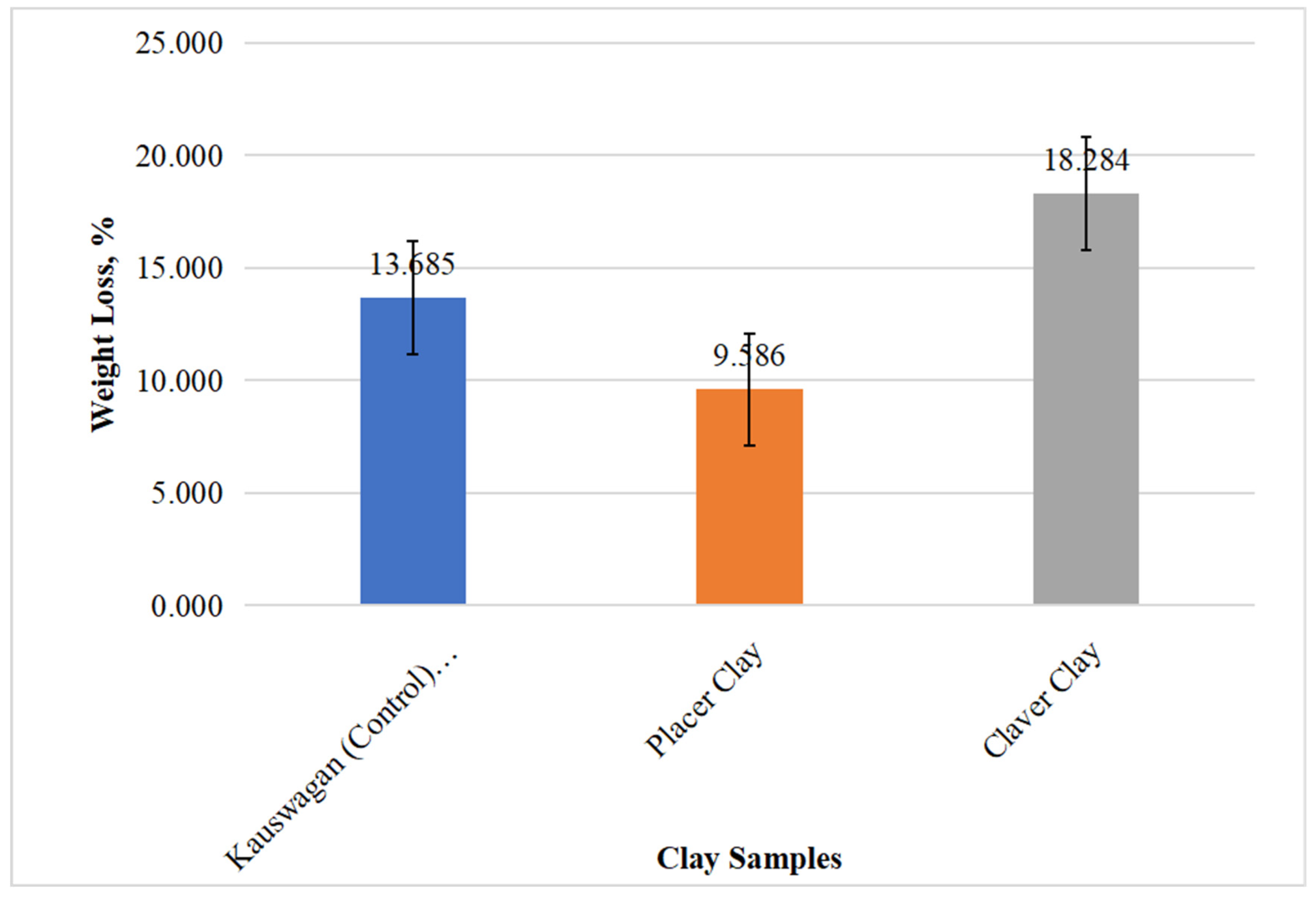
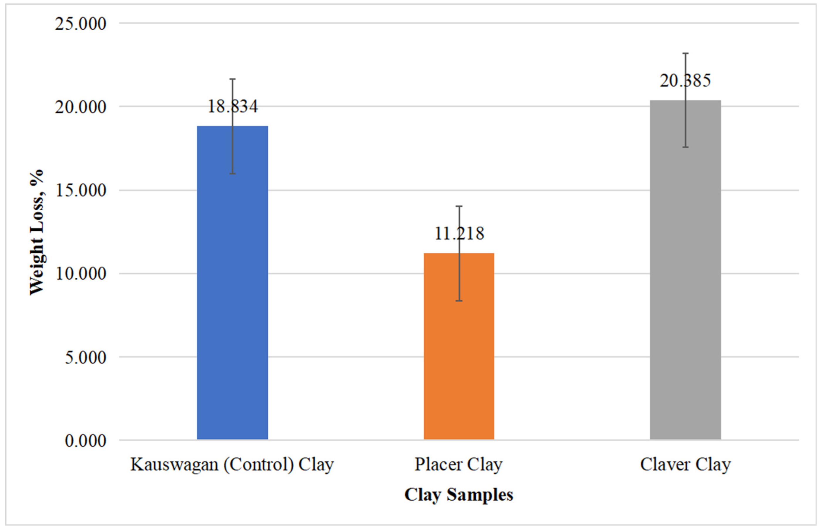
Figure 4.7 indicated the average loss on ignition values for three samples: Kauswagan, Placer, and Claver. According to the data, Kauswagan had a weight percent loss for pellet samples with values of 18.834%, Placer had a weight percent loss on pellet samples with values of 11.218%, and Claver had a weight percent loss on the pellet samples with values of 20.385%. As depicted in the graph, Placer displayed the lowest percentage of weight loss, whereas Claver showed the highest percentage weight loss on both samples. This observation suggested that Placer had a relatively lower presence of organic matter compared to Kauswagan, while Claver had a higher presence of organic matter compared to Kauswagan. Furthermore, this graph trend was also observed with the total linear shrinkage of samples, which further implied that the percent total linear shrinkage of the samples was directly proportional to the percent weight loss. In terms of the results on the loss on ignition, Placer could be utilized for refractory applications such as refractory bricks, since its percent loss on ignition fell within the standard limits of 8%-18.0% [60].
Figure 4.7.
Average percent weight loss of pellet samples from three varieties of clay fired at 850°C after undergoing the shrinkage test.
Figure 4.7.
Average percent weight loss of pellet samples from three varieties of clay fired at 850°C after undergoing the shrinkage test.
4.2.4. Water Absorption
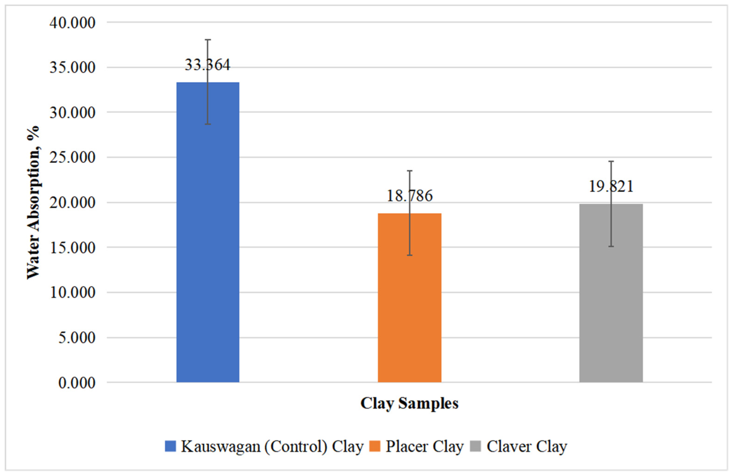
Depicted in Figures 4.8 and 4.9 was the graph of the average water absorption values for three samples: Kauswagan, Placer, and Claver. As shown in the graph, Kauswagan exhibited water absorption values of 36.563% for test bar samples and 33.364% for pellet samples, Placer displayed water absorption values of 21.879% for test bar samples and 18.786% for pellet samples, and Claver exhibited a percent water absorption of 19.821% for the pellet samples. However, for the test bar samples of Claver, there was no available data for the water absorption due to the breakage of test bar samples during firing. The mentioned values manifested that Kauswagan had the highest capacity to absorb and retain water in comparison to Placer and Claver samples due to its alumina (Al2O3) content (see Table 4.1), which contributed to the absorption capacity of the samples. The data displayed in the figure revealed that both Placer and Claver clay exhibited a water absorption rate of less than 25%. According to Ndjigui et.al. [62], the amount of water absorbed was an important quality factor that showed how porous the clay material was. When the water absorption rate was below 25%, it indicated that the ceramic piece had better quality and could be utilized in tile manufacturing. Such ceramics were known to have increased durability, lasting longer, and exhibit enhanced resistance to various weather conditions.
Figure 4.8.
Average percent water absorption of test bar samples for the three varieties of clays fired at 850°C after weighing out the total weight loss on ignition.
Figure 4.8.
Average percent water absorption of test bar samples for the three varieties of clays fired at 850°C after weighing out the total weight loss on ignition.
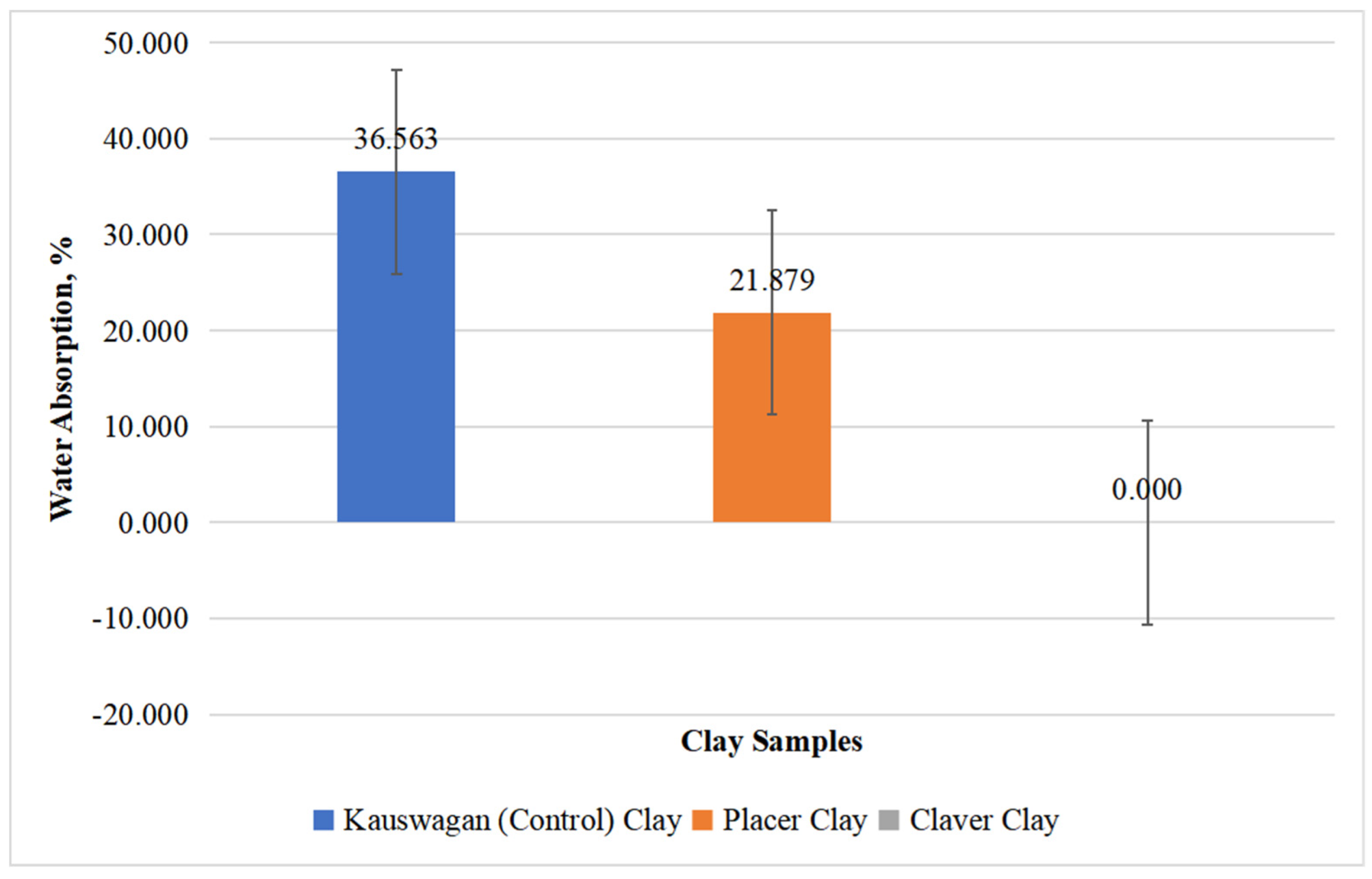
Figure 4.9.
Average percent water absorption of pellet samples for the three varieties of clays fired at 850°C after weighing out the total weight loss on ignition.
Figure 4.9.
Average percent water absorption of pellet samples for the three varieties of clays fired at 850°C after weighing out the total weight loss on ignition.
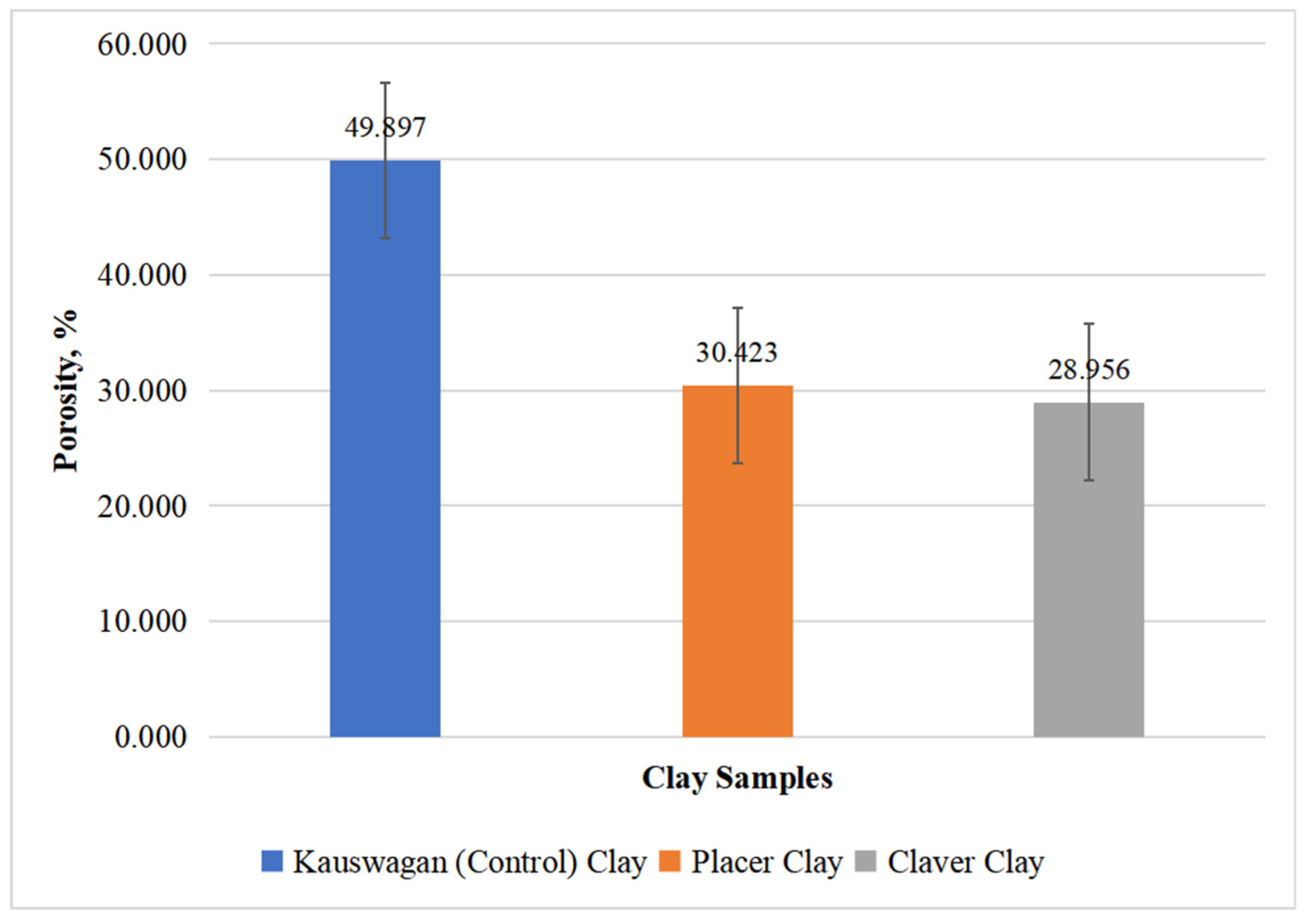
4.2.5. Apparent Porosity
The graphs showed the average percent apparent porosity for three samples: Kauswagan, Placer, and Claver. As depicted in the graph, Kauswagan and Placer exhibited apparent porosity values of 57.911% and 35.523% for test bar samples, respectively. However, there was no available data for the apparent porosity value of Claver due to the breakage of test bar samples during firing, hence, no sample was used for the test. As for the average percent apparent porosity of pellet samples of Kauswagan, Placer, and Claver, it displayed the following values of 49.897%, 30.423%, and 28.596%, accordingly. The findings suggested that Kauswagan had the highest number of porosity compared to both Placer and Claver. Based on Teixeira et al. [59], a clear correlation was observed between apparent porosity and water absorption, with higher porosity resulting in increased water absorption. The Placer sample showcased a significant water absorption rate of 21%, suggesting its suitability for the production of roof tiles and ceramic blocks (see Appendix H). Unfortunately, no data could be collected for the Claver sample as it broke during the firing process. However, considering the drying and firing cycles, the total linear shrinkage remained below the specified limit of 6%. As a result, it was recommended to restrict the production of porous ceramic products according to Teixeira et al. [59].
Figure 4.10.
Average percent apparent porosity of the test bar samples of the three varieties of clays after undergoing fabrication processes and was fired at 850°C.
Figure 4.10.
Average percent apparent porosity of the test bar samples of the three varieties of clays after undergoing fabrication processes and was fired at 850°C.
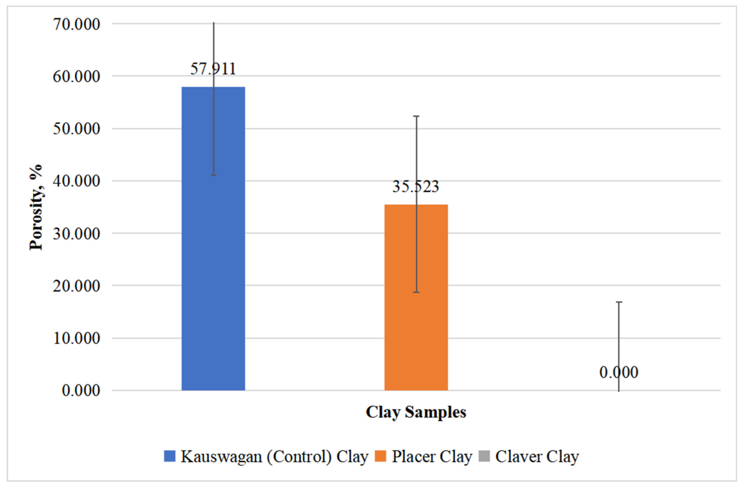
Figure 4.11.
Average percent apparent porosity of the pellet samples of the three varieties of clays after undergoing fabrication processes and was fired at 850°C.
Figure 4.11.
Average percent apparent porosity of the pellet samples of the three varieties of clays after undergoing fabrication processes and was fired at 850°C.
4.2.8. Color Analysis
Table 4.4 showed the average color of both test bars and pellet samples of Placer and Claver with Kauswagan as the basis. As observed in the table, the average differences in the lightness/darkness (ΔL) of the Placer (22.20 and 16.33) were higher than those of Claver (8.06 and 7.31), which indicated that the fired Placer samples were lighter in color than the Claver samples for both test bars and pellets. The average differences in greenness/redness (Δa) of the two samples were Placer (-11.86 and -12.29) and Claver (11.44 and -9.78), both depicted a shift towards the green color. Regarding the average differences in the blueness/yellowness (Δb) of the samples, Placer (25.33 and 21.02) was way higher compared to Claver (15.25 and 13.35), thus implying that Placer shifted towards a more yellowish color than Claver. As for the average change in color (ΔE), Placer illustrated higher values of 25.33 and 21.02 than Claver with values of 15.24 and 13.35 for test bars and pellet samples, respectively. This further manifested that the color difference between Placer from the reference color was way greater than Claver and the reference color. The fired Placer samples exhibited a lighter shade compared to the Claver samples (see Figure 4.12), with both samples displaying a slight shift towards green. Additionally, the Placer sample displayed a more yellowish hue in comparison to Claver. Both samples have the potential to be utilized in the production of lighter products that can command higher prices compared to red ceramics. The Placer sample, in particular, showcased exceptional attributes such as its light colors and high rupture strength, making it well-suited for various applications in structural ceramics according to Dong et al. [63].
Table 4.4.
Average color of test bars and pellets samples fired at 850°C.
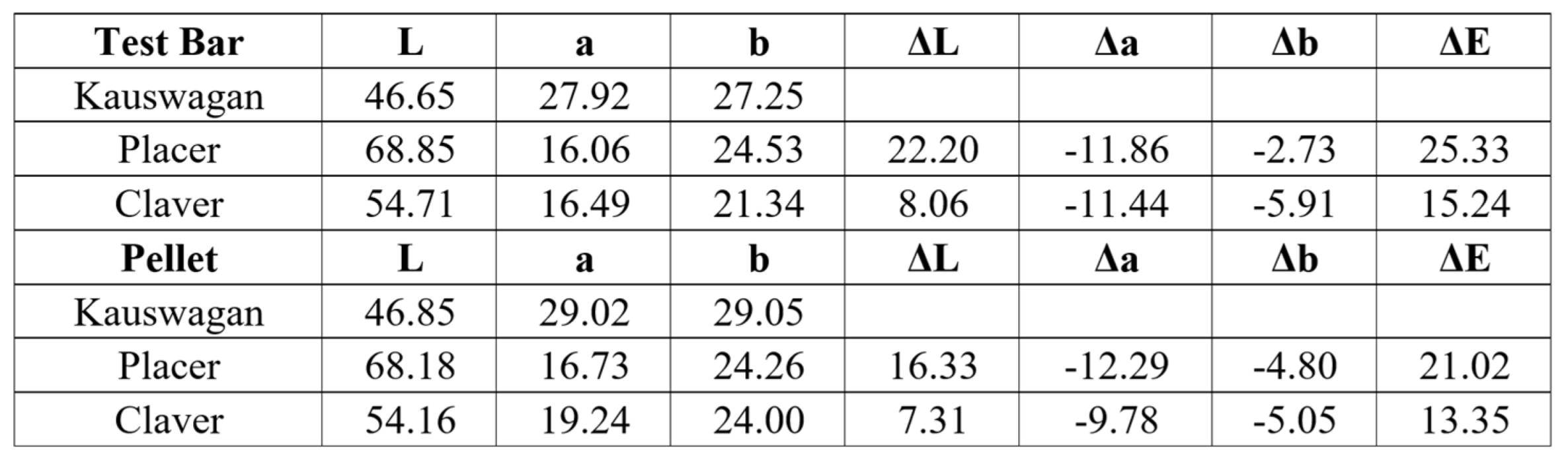
Figure 4.12.
Observed color of the test bar samples of (a) Kauswagan, (b) Placer, and (c) Claver after being fired at a temperature of 850°C.
Figure 4.12.
Observed color of the test bar samples of (a) Kauswagan, (b) Placer, and (c) Claver after being fired at a temperature of 850°C.

4.3. Mechanical Property Testing
4.3.1. Modulus of Rupture
The chart presented the flexural strengths of the three samples: Kauswagan, Placer, and Claver. Based on the data, Kauswagan was observed to have a Modulus of Rupture (MOR) value of 0.948 MPa, while Placer displayed a value of 3.486 MPa. However, there was no available data for the flexural strength of Claver due to the breakage of test bar samples during firing. Hence, Claver samples did not undergo the MOR test. From the graph, it can be concluded that Placer had a higher flexural strength compared to Kauswagan. Teixeira et al. (2004) reported that the minimum expected flexural strength of ceramic pieces fired at 855°C is 1.96 MPa for massive bricks, 5.39 MPa for ceramic blocks, and 6.37 MPa for roof tiles (see Appendix H). This data suggests that Placer clay belonged to the category of massive bricks, given its flexural strength ranging from 1.96 MPa to 5.39 MPa, with a measured value of 3.486 MPa.
Figure 4.13.
Average modulus of rupture of test bars samples of the three varieties of clays identified fired at 850°C after undergoing the fabrication processes.
Figure 4.13.
Average modulus of rupture of test bars samples of the three varieties of clays identified fired at 850°C after undergoing the fabrication processes.
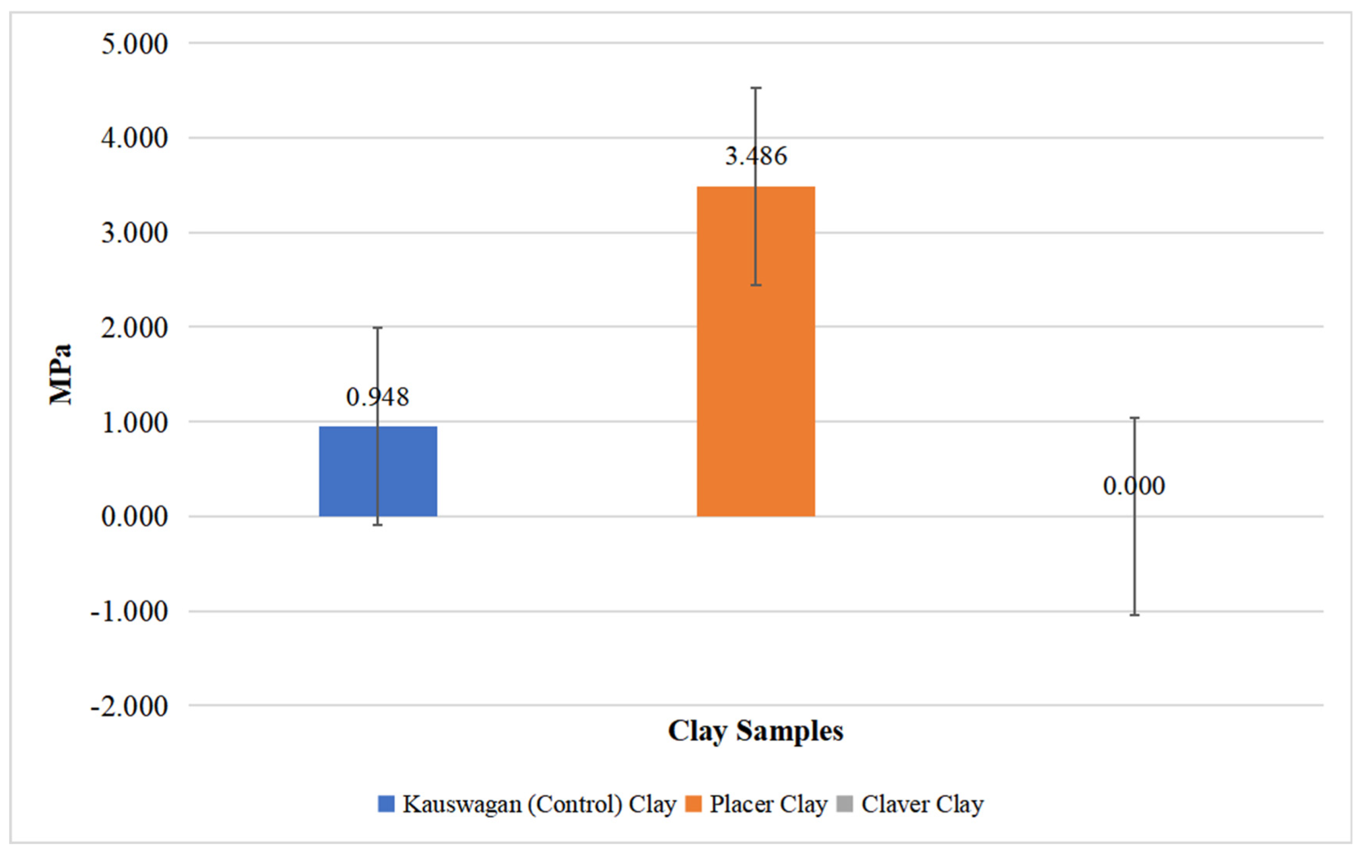
4.4. Map Generation
4.4.1. Mapping and Profiling
The geographic coordinates of the newly established boundary were recorded and verified on-site (see Appendix G). Similarly, the coordinated points are stored in Google Earth. The resulting sample map, illustrated in Figures 4.14 and 4.15, provided a clear visual representation of the sampling site and its boundaries. Stated below is also the general overview of the clay minerals mapped and can be found in whole Surigao del Norte province (see Figure 4.16) and its position on google earth’s perspective (see Figure 4.17)
Figure 4.14.
Clay mineral sampling map in Brgy. Bugas-Bugas, Placer.
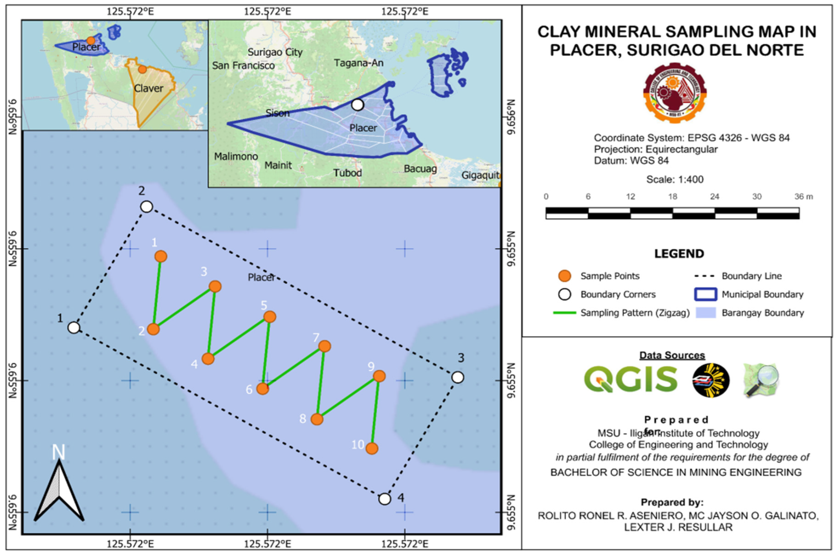
Figure 4.15.
Clay mineral sampling map in Brgy. Cabugo, Claver.
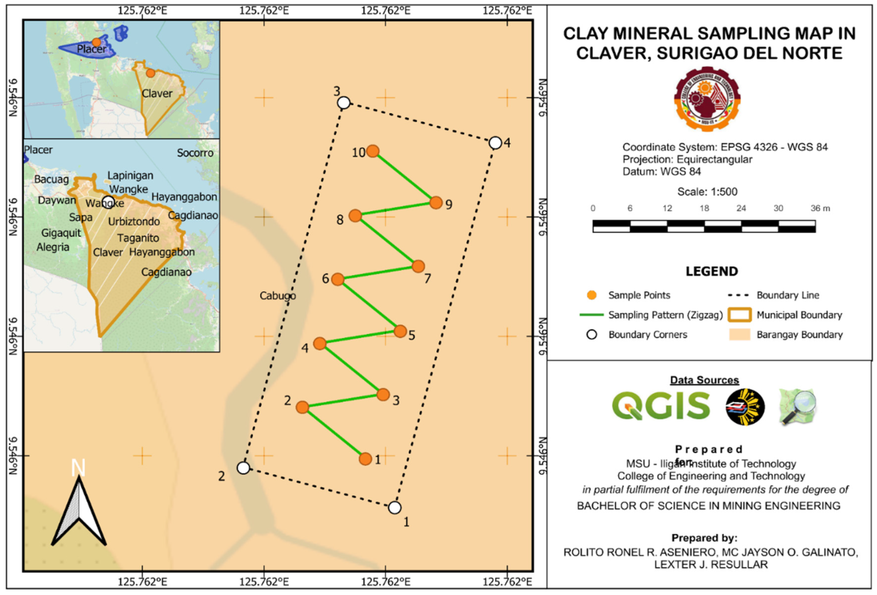
Figure 4.16.
Clay mineral resource map in Surigao del Norte.
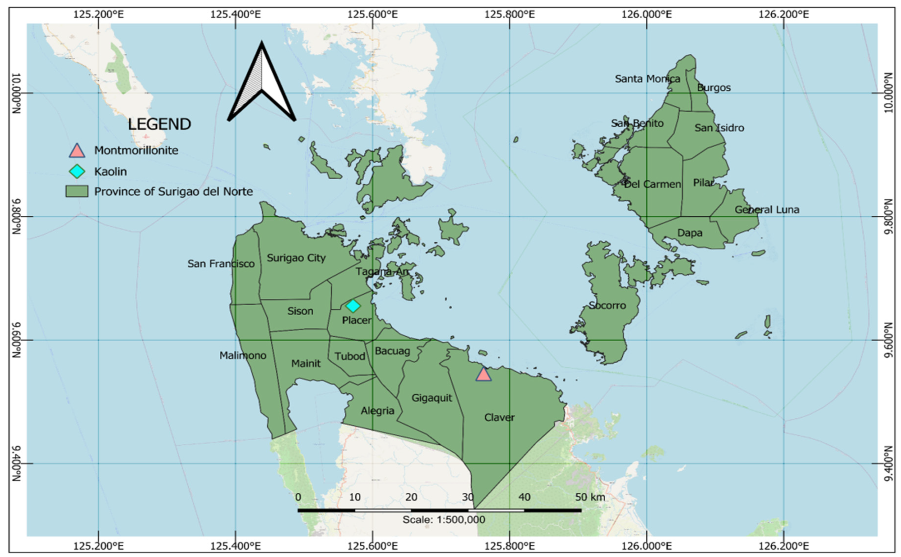
Figure 4.17.
Location of clay mineral resources in Google Earth.
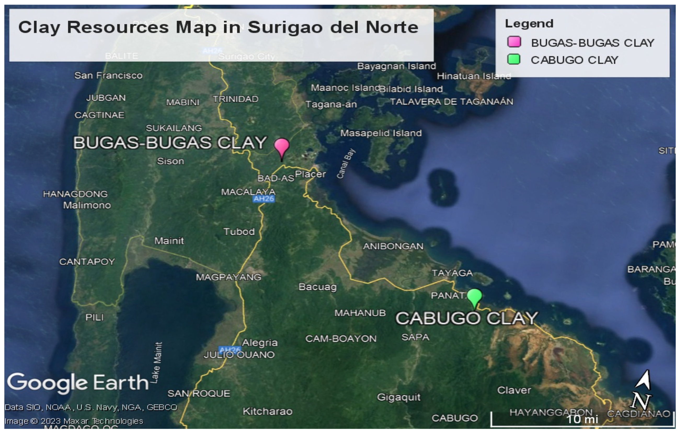
Chapter V. Conclusions and Recommendations
This chapter summarizes the results and findings of the study and based on the findings, conclusions were drawn, and recommendations are given.
5.1. Conclusion
The examination of the obtained samples revealed the presence of clay resources at the specified areas because of the significant properties surrounding the location. Specifically, Brgy. Bugas-Bugas, in Placer was discovered to be composed of dickite clay, with significant amount of quartz and anorthite content, indicative of a siliceous secondary clay. On the other hand, Brgy. Cabugo, Claver, Surigao del Norte was dominated by Montmorillonite. These findings underscore the suitability of both locations for clay extraction, suggesting promising prospects for mapping and further development. Subsequently, it was proven that by the use of GPS Garmin Orgeon 550 model and further assistance of QGIS, clay resources can be mapped accordingly. More so, this detailed information is fundamentally significant for variety of resource people in different relevant sectors interested in clay mineral resources. For, understanding the composition and distribution of clay types can help with industrial development decisions, direct resource management, and economic planning sustainability. Furthermore, it lays a platform for other related research work in maximizing clay resources around the area for sustainable development.
5.2. Recommendations
- Employing Thermogravimetric Analysis (TGA) and Differential Scanning Calorimetry (DSC) to gather structured and profound information into the thermal properties and behavior of the clay considering its environment.
- Conduct of additional physical testing such as specific gravity, and particle size to gain in-depth understanding of the clay’s properties on samples taken.
- Employ drilling techniques to conduct thorough exploration of the clay resource and accurately estimate the clay reserve.
- Expand the mapping on areas closely related to Brgy. Bugas-Bugas in Placer and Brgy. Cabugao in Claver Surigao del Norte for further discovery of other types of clay resources with significant physical and mechanical properties.
- Connect with the Local Government Unit to make sure that the mapping of and profiling of the identified clay will be known locally and used for community’s advancement.
- Submerged to Indicated and Measured level of Exploration Stage in mining life cycle to get probable and proven sample and increase geological sampling confidence.
Acknowledgments
We would like to express our deepest appreciation and gratitude to all the individuals and entities who contributed significantly to the successful completion of our research.
- -
- to Engr. Larry M. Heradez, MGB Regional Director of Caraga Region, and staff for their invaluable support and guidance, greatly benefiting the study.
- -
- also extending appreciation to Mayor Georgia Gokiangkeee for lending us the crucial GPS device, instrumental in the successful implementation of our research fieldwork.
- -
- to the House Technology Industries PTE. Ltd, especially to Ma’am Roxanne Climacosa for their valuable assistance in our research sample analysis.
- -
- to our advisers Engr. Seigfreid Kempis and co-adviser, Engr. Lori-ann Cabalo, whose dedication, and commitment shaped the success of our research.
- -
- to our parents for their unconditional love, care, unwavering financial support, and encouragement to move along.
- -
- to our classmates for their invaluable assistance and support by stimulating discussion where some ideas are solicited for the fulfillment of the research.
- -
- above all, to God for providing unwavering guidance, sustenance, and bestowed protection in the entire duration of our research.
Appendix A. (Sample Collection and GPS Coordinates Recording)
A.1 Sampling and GPS Coordinates Recording
Figure A.1.1.
Performing Composite Sampling Method (zigzag pattern), 10 sampling points with a regular interval of 10 meters.
Figure A.1.1.
Performing Composite Sampling Method (zigzag pattern), 10 sampling points with a regular interval of 10 meters.
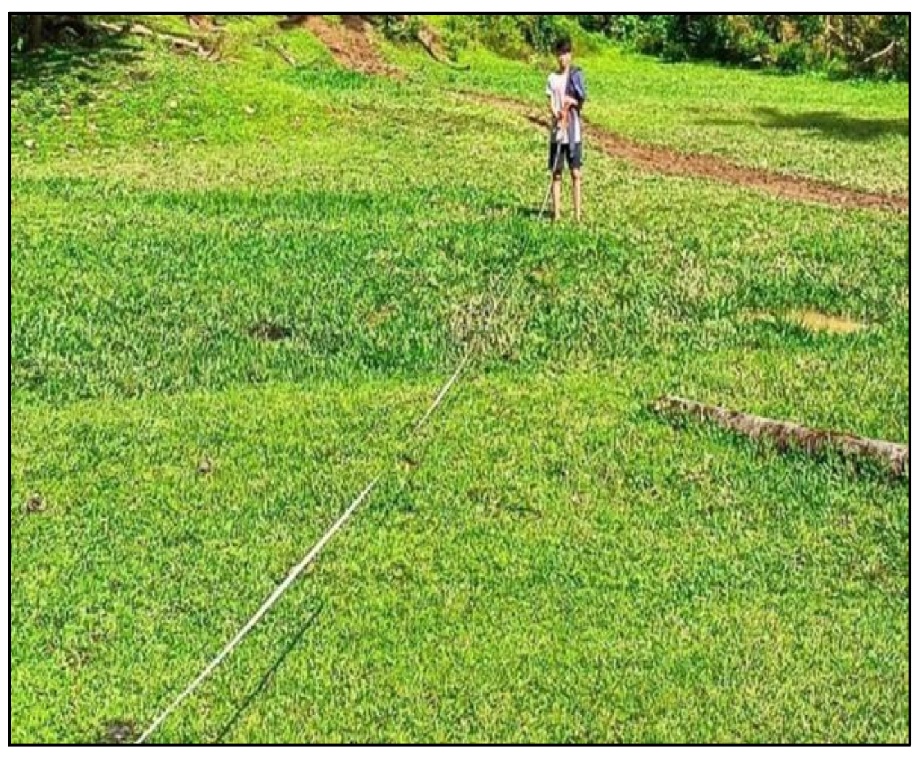
Figure A.1.2.
Scraping and Trenching to access the upper layer of prospected clay deposit.
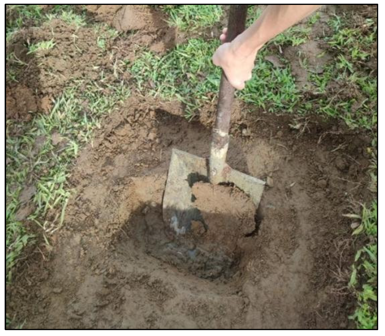
Figure A.1.3.
Collecting four kilograms of sample at each sample point.
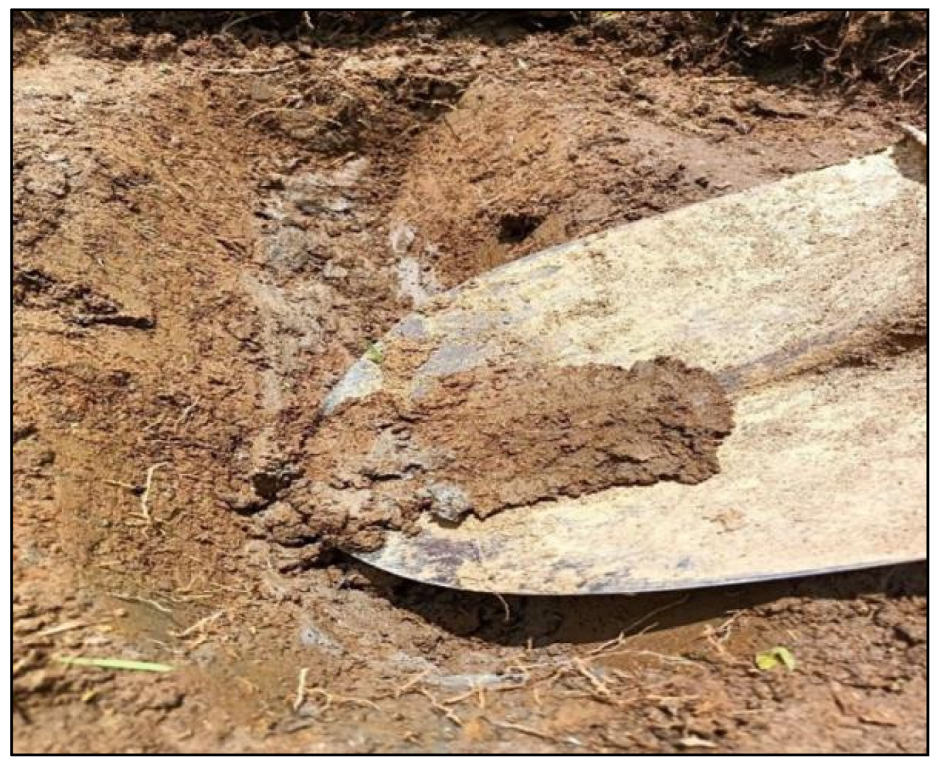
Figure A.1.4.
Labelling location via GPS coordinates and elevation (above mean sea level).
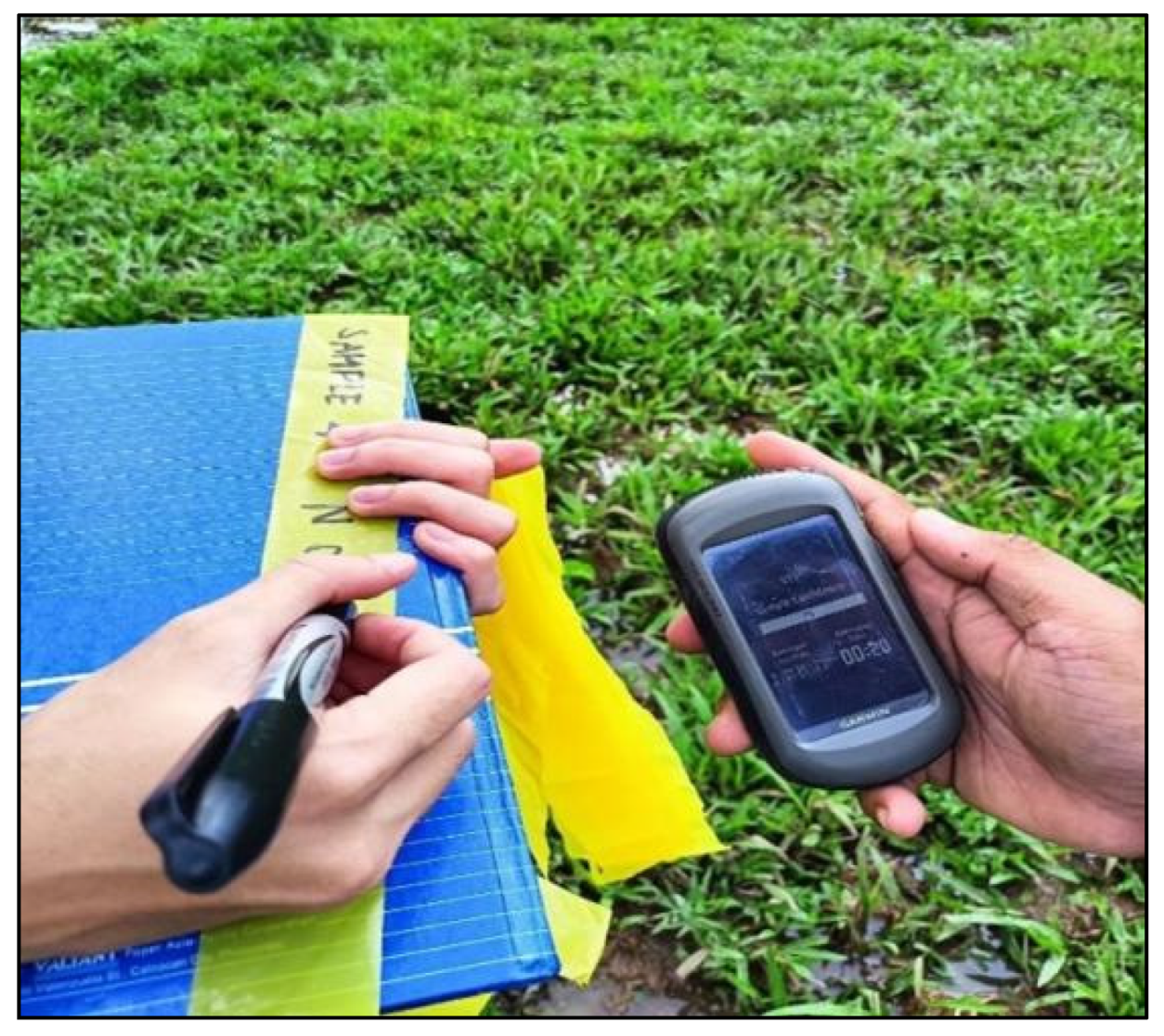
Appendix B. (Fabrication Process)
B.1 Sample Preparation
Figure B.1.1.
Clay sample preparation: pulverizing.

Figure B.1.2.
Clay sample preparation: 60-mesh sieving.
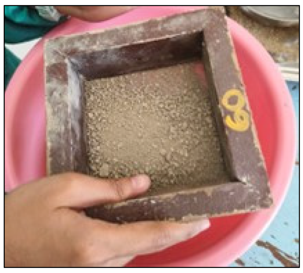
B.2 Fabrication Process
B.2.1 Test Bar Making
Figure B.2.1.1.
Containing the mold 100 grams of pulverized clay samples.
Figure B.2.1.2.
Hydraulic pressing at 40N of controlled force.
Figure B.2.2.1.
Placing 4 grams of pulverized aged sample into the pelletizer.
Figure B.2.2.2.
Pressing and compacting by the pelletizer.
B.2.3 Drying and Firing
Figure B.2.3.1.
Test bars and Pellets Oven Drying at 110° C of temperature.
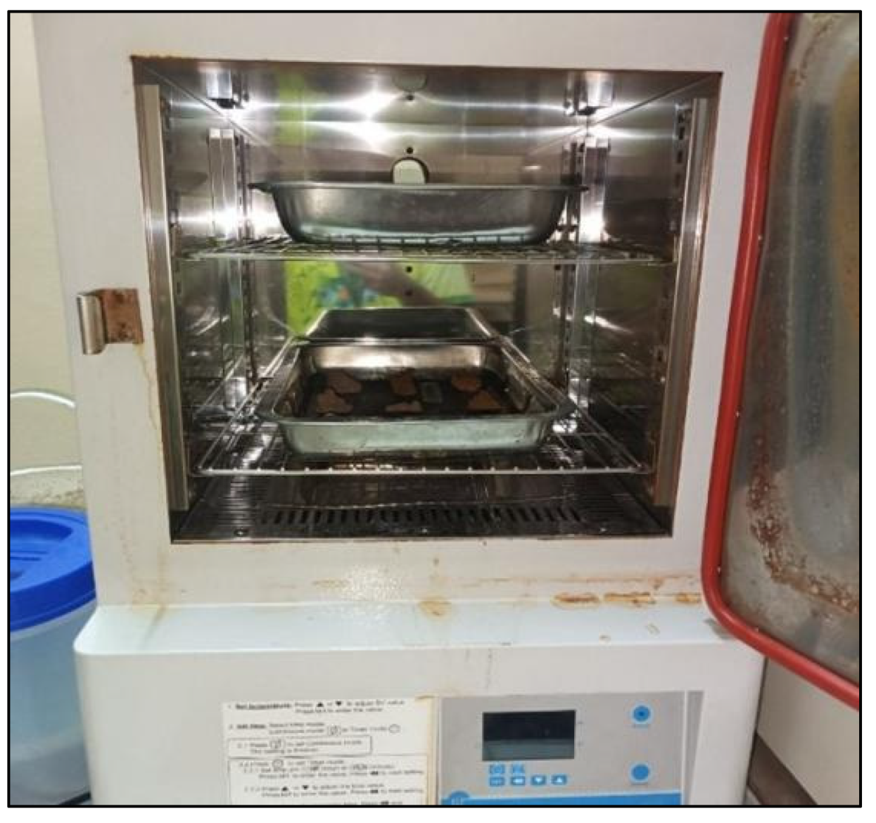
Figure B.2.3.2.
Kiln Firing of Test bars and Pellets.
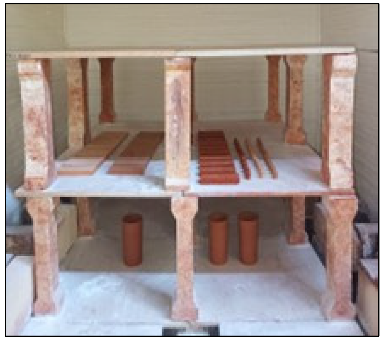
Appendix C. (Characterization of Samples)
C.1 Physical Property Testing
C.1.1 Shrinkage Test
Figure C.1.1.1.
Post test bar drying and firing weighing.
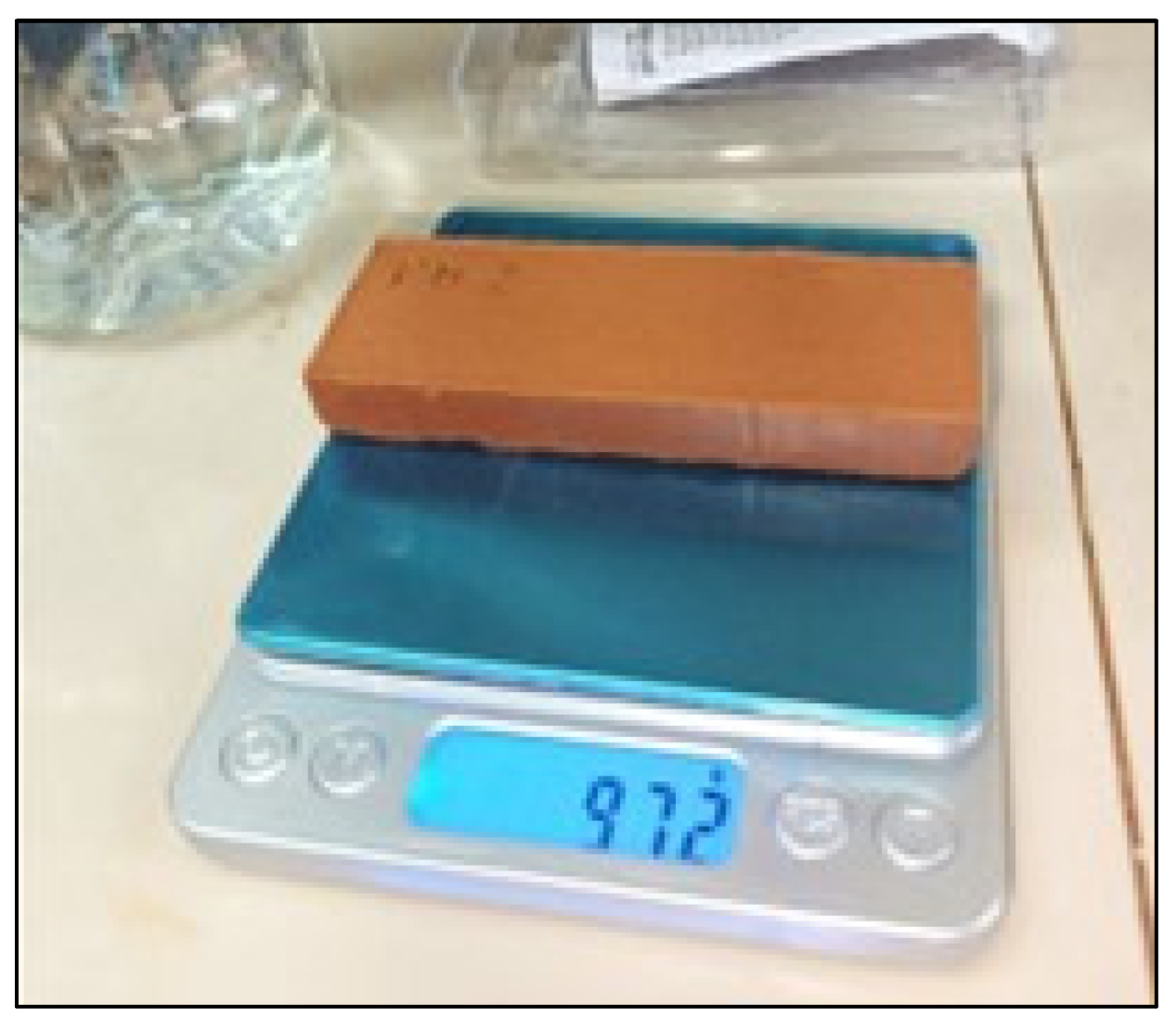
Figure C.1.1.2.
Post pellet drying and firing weighing.
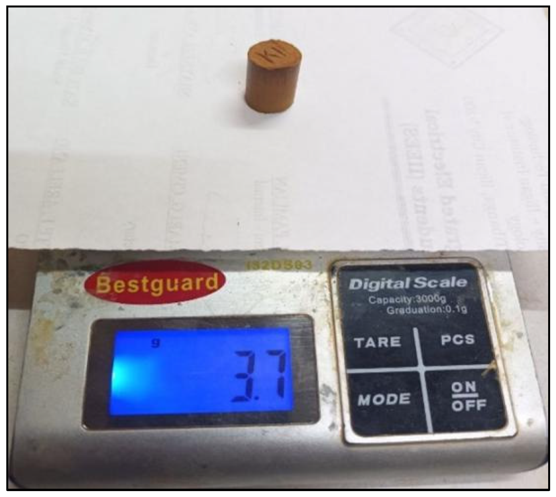
C.1.2 Water Absorption
Figure C.1.2.1.
Boiling of samples for water absorption test at 100°C.
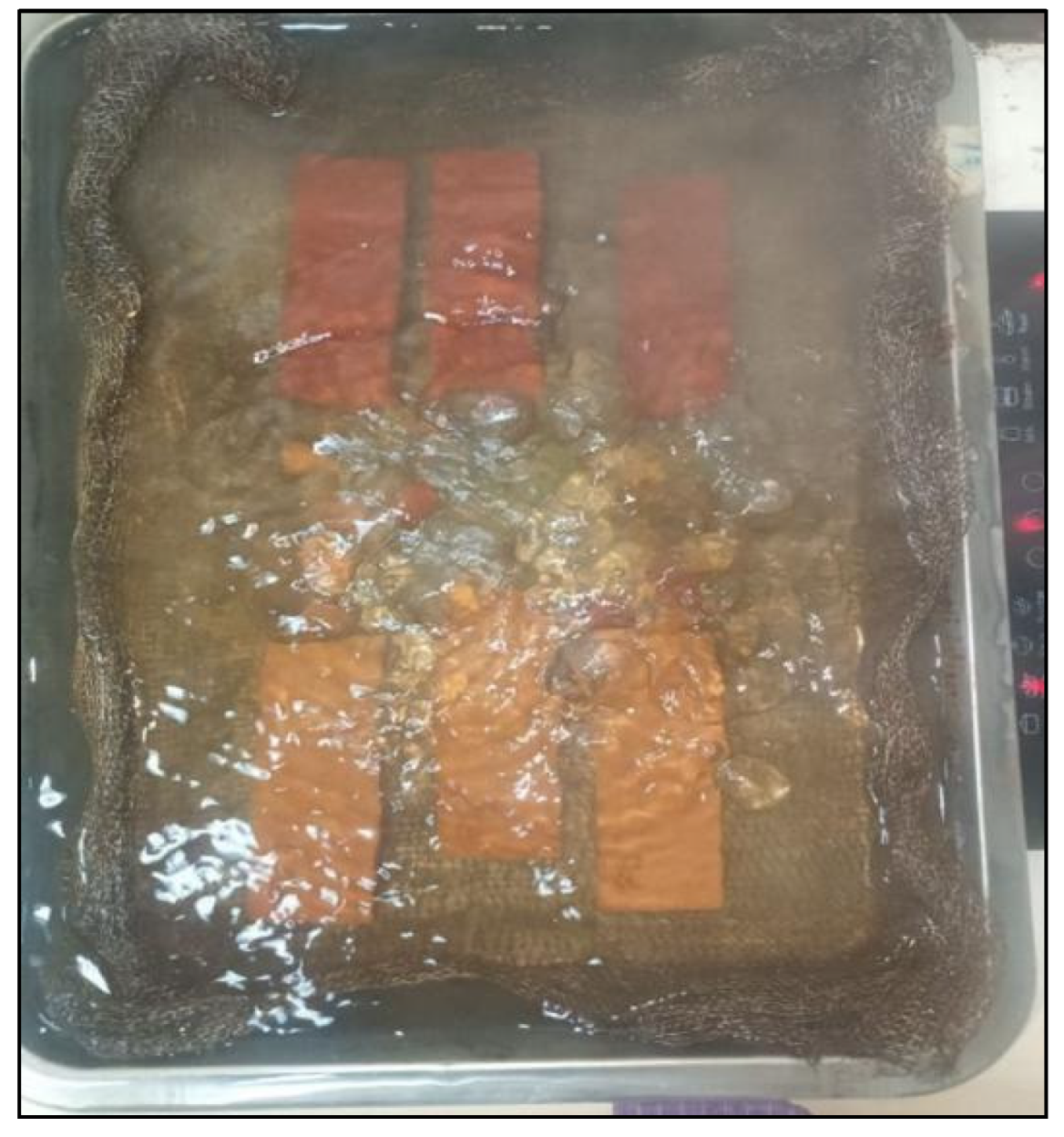
C.1.3 Apparent Porosity
Figure C.1.3.1.
Test bar weighing.
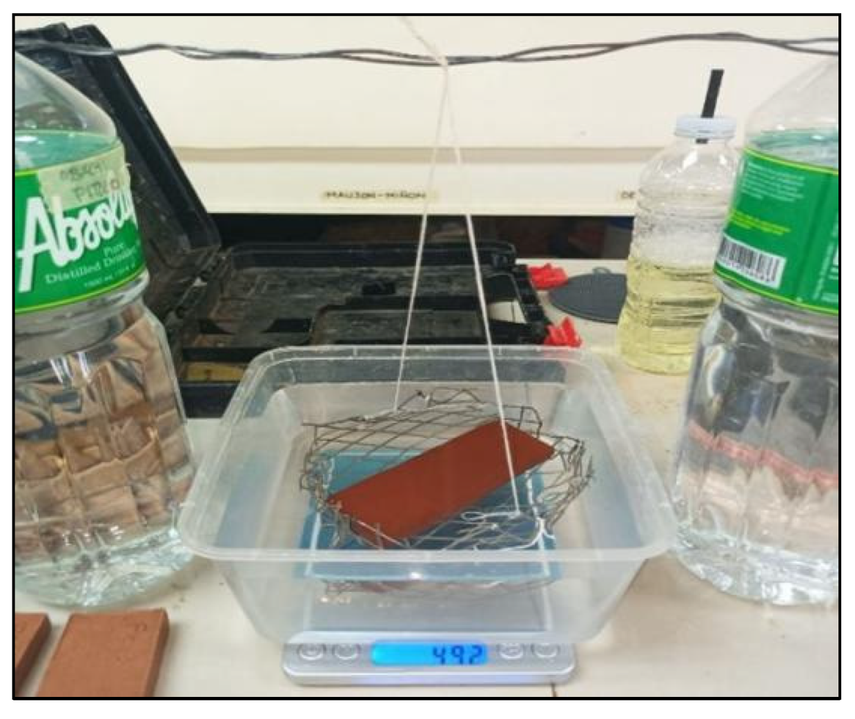
Figure C.1.3.2.
Pellet weighing.
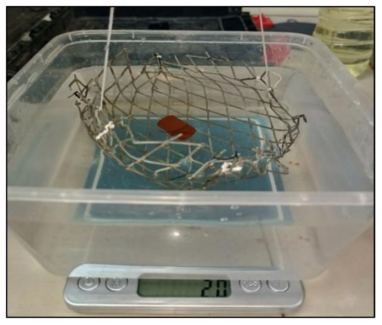
C.1.4 Color Test
Figure C.1.4.1.
Color analysis using spectrophotometer.
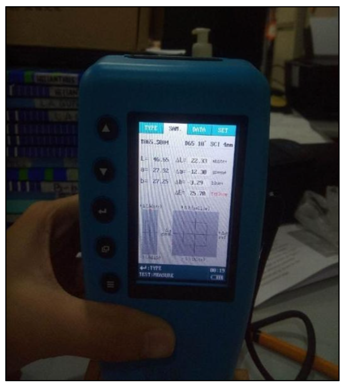
C.2 Mechanical Property Test
C.2.1 Modulus of Rupture Test
Figure C.2.1.1.
Three-point bend testing of samples.
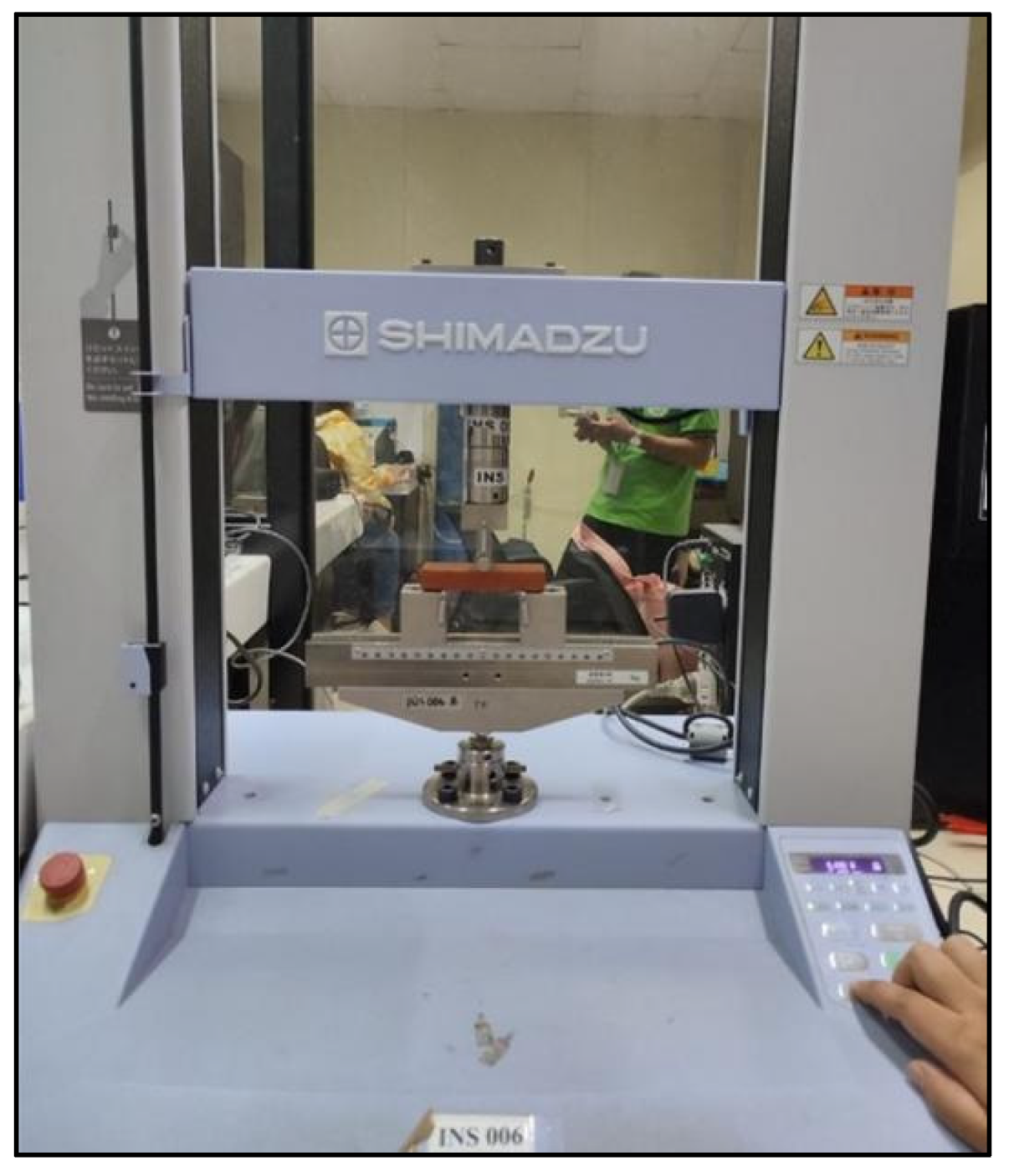
Appendix D. (XRF Analysis Results)
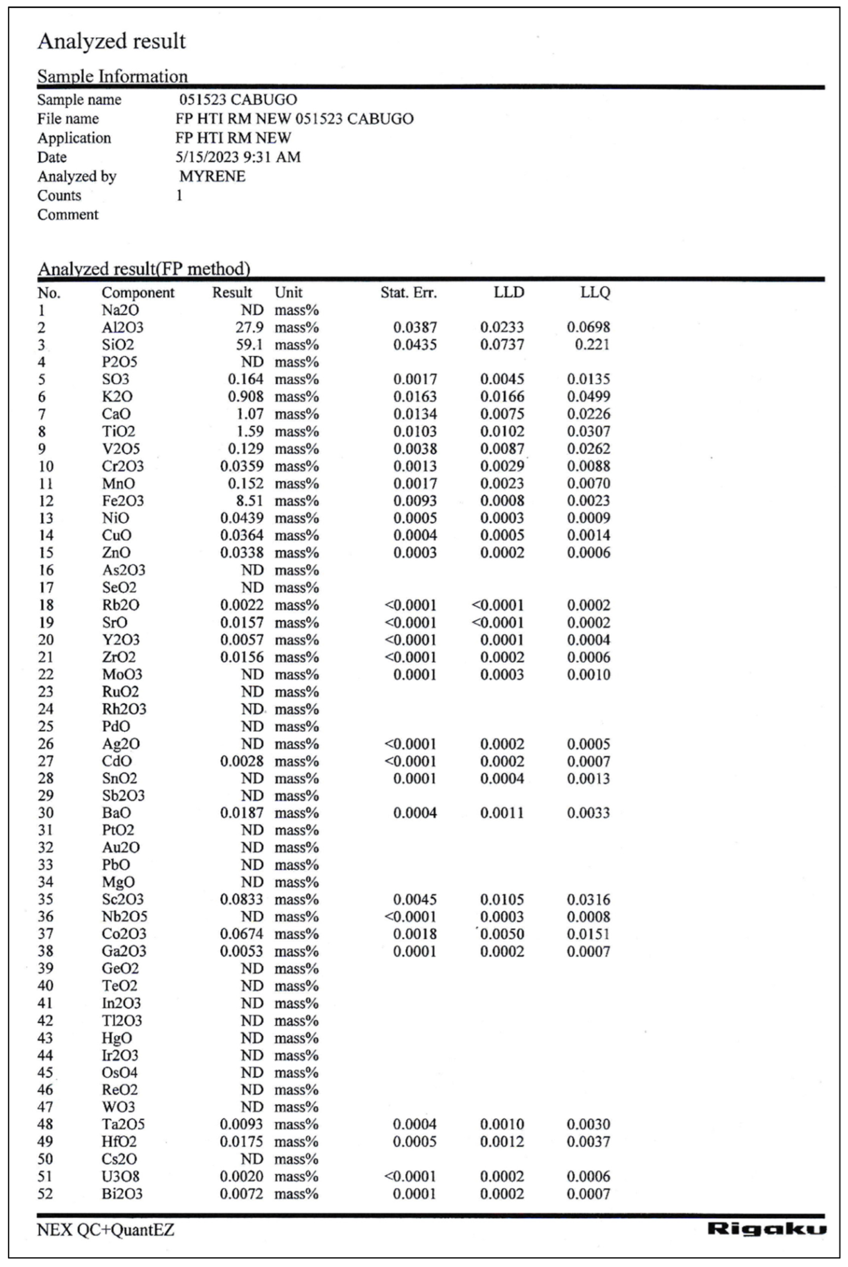
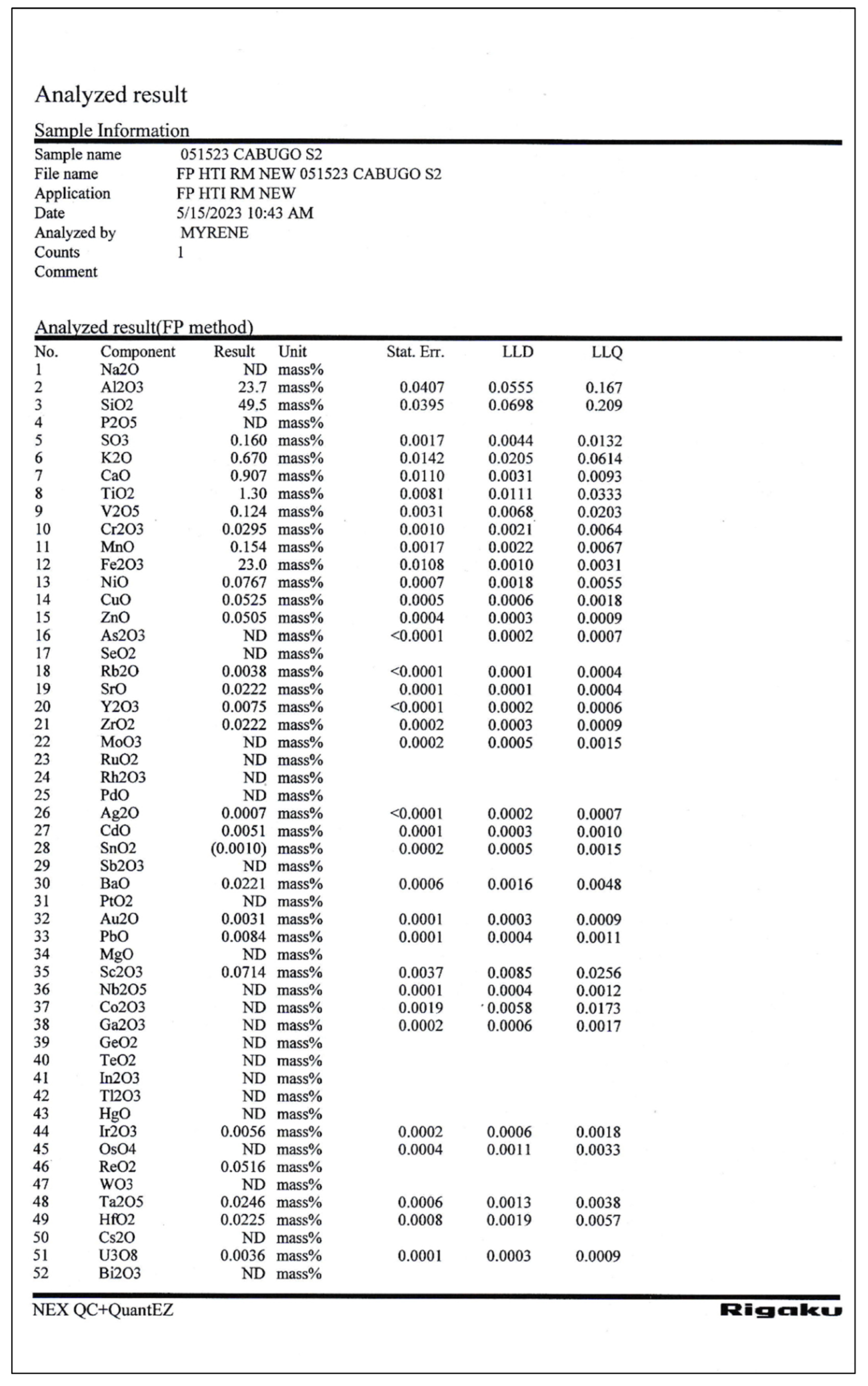
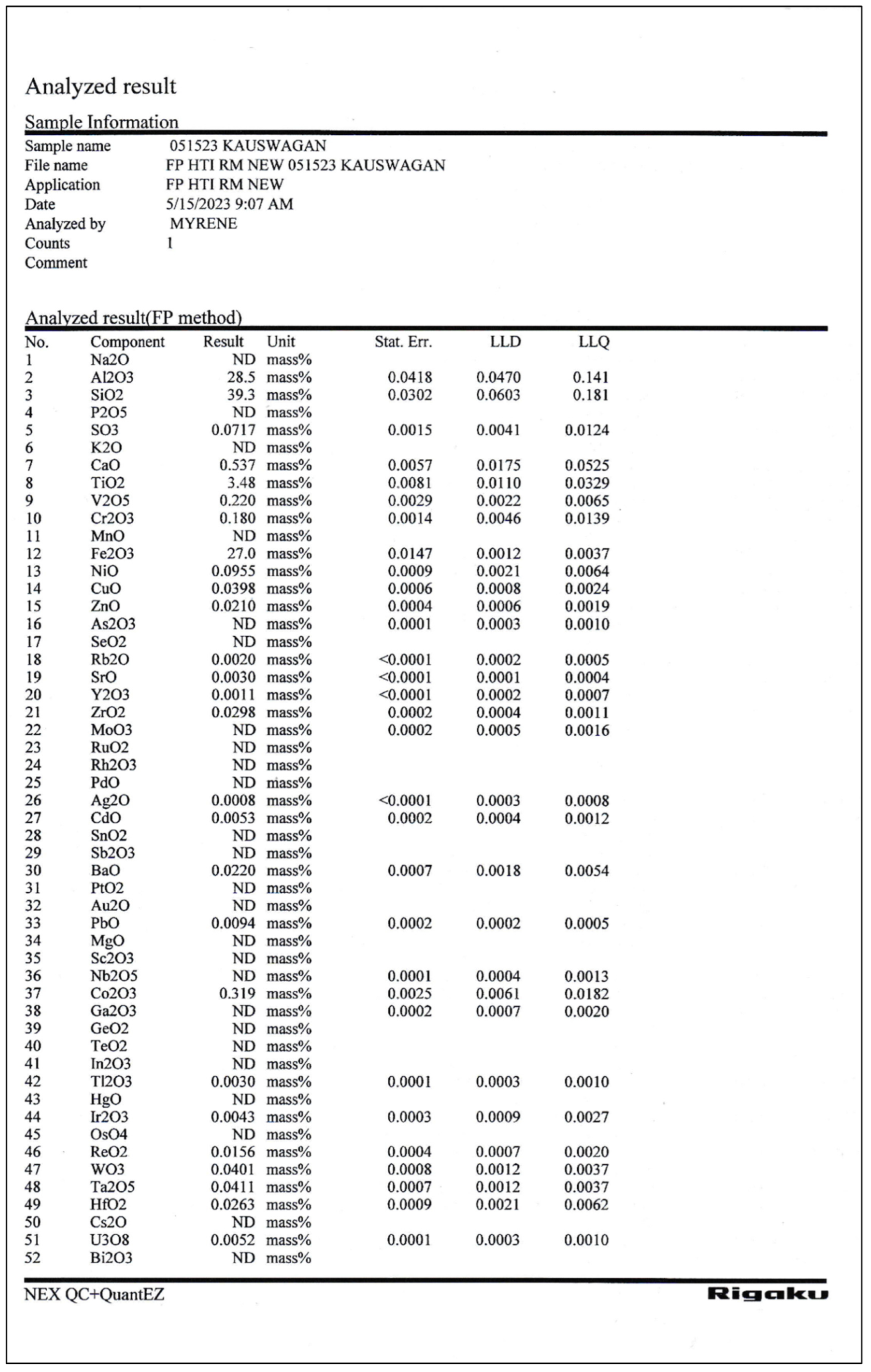
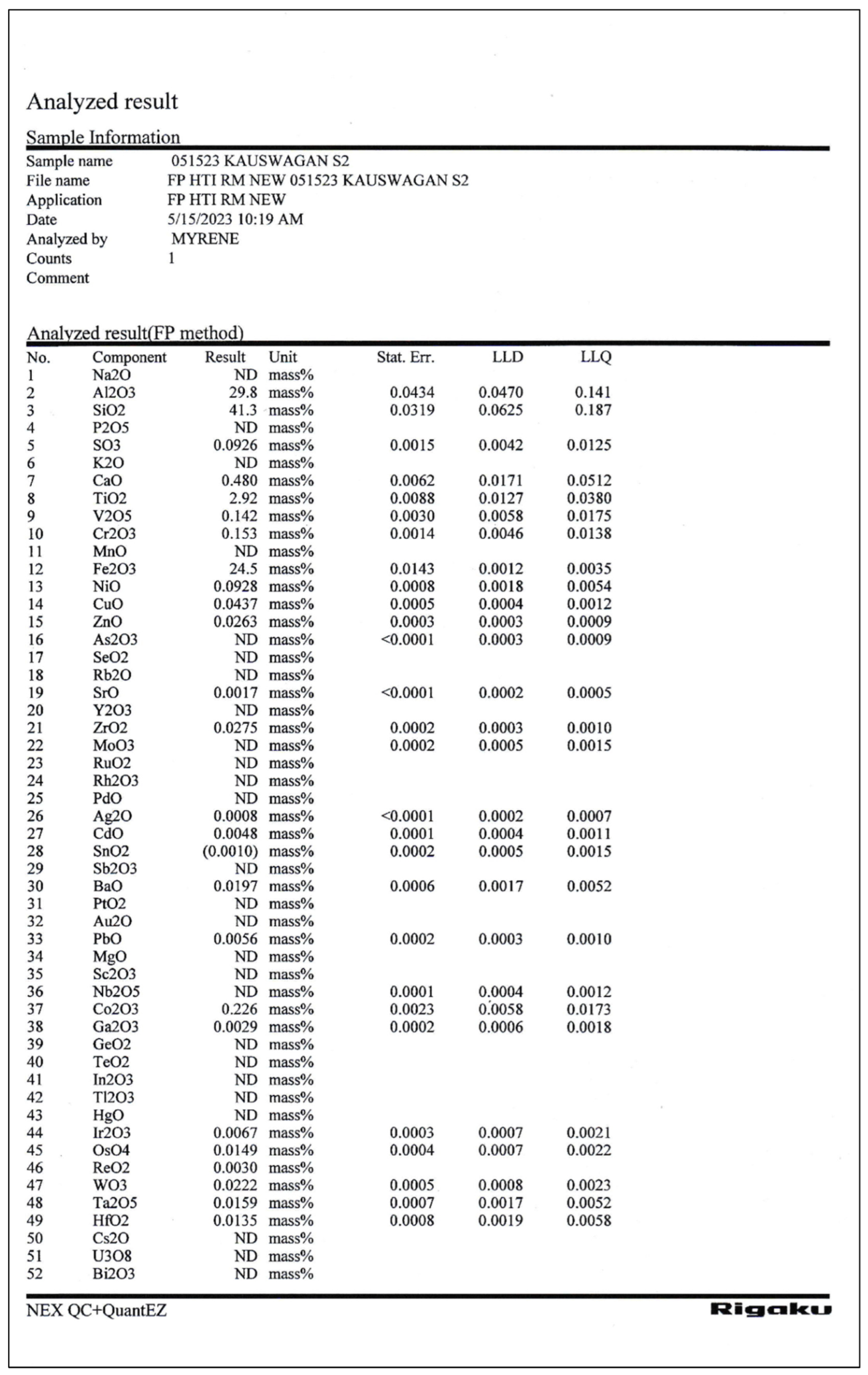
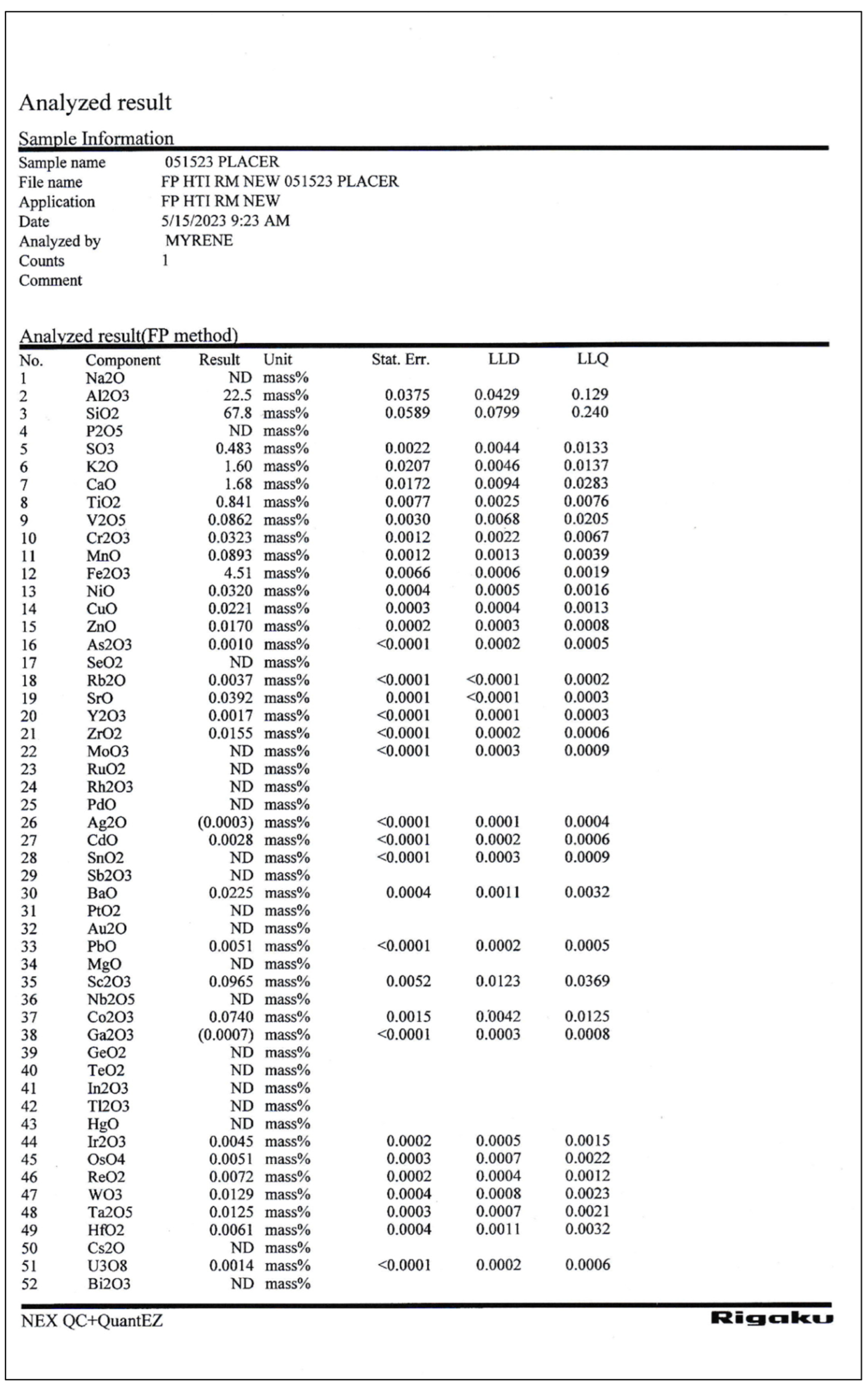
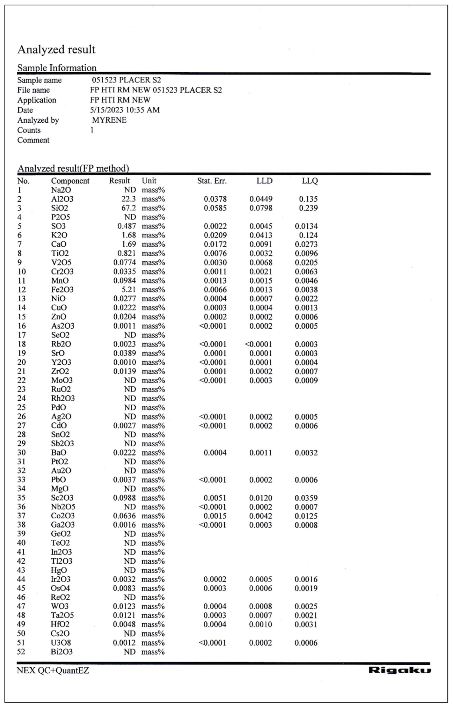
Appendix E. (XRD Analysis Results)
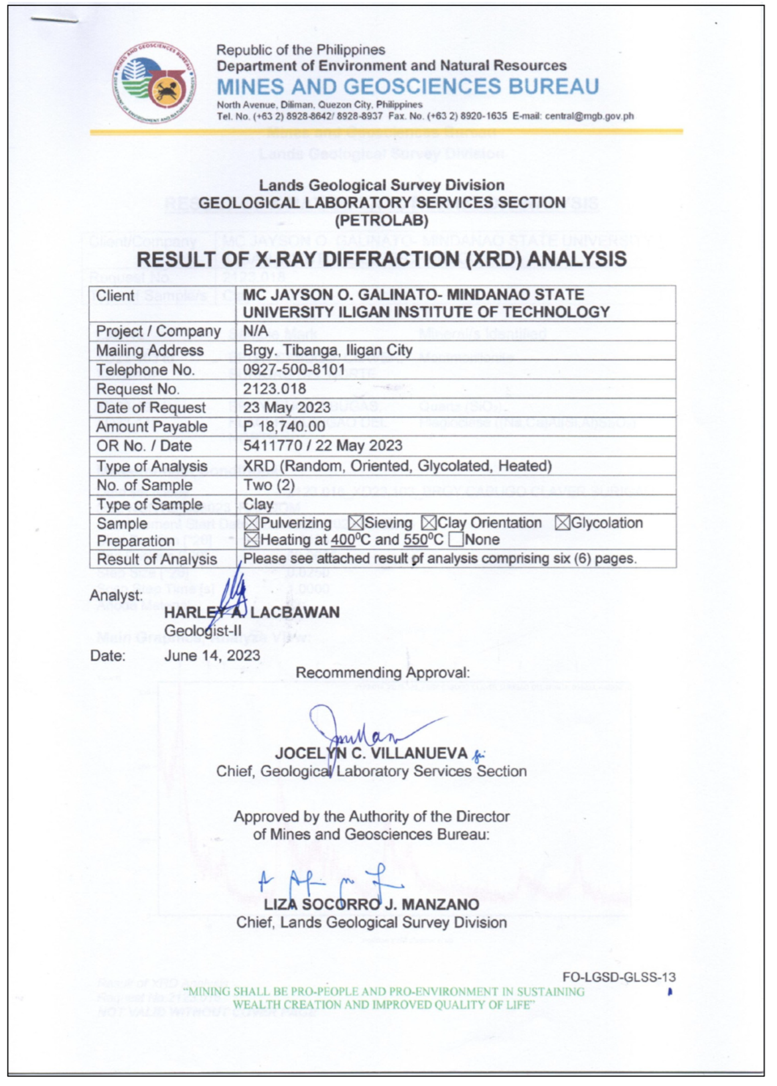
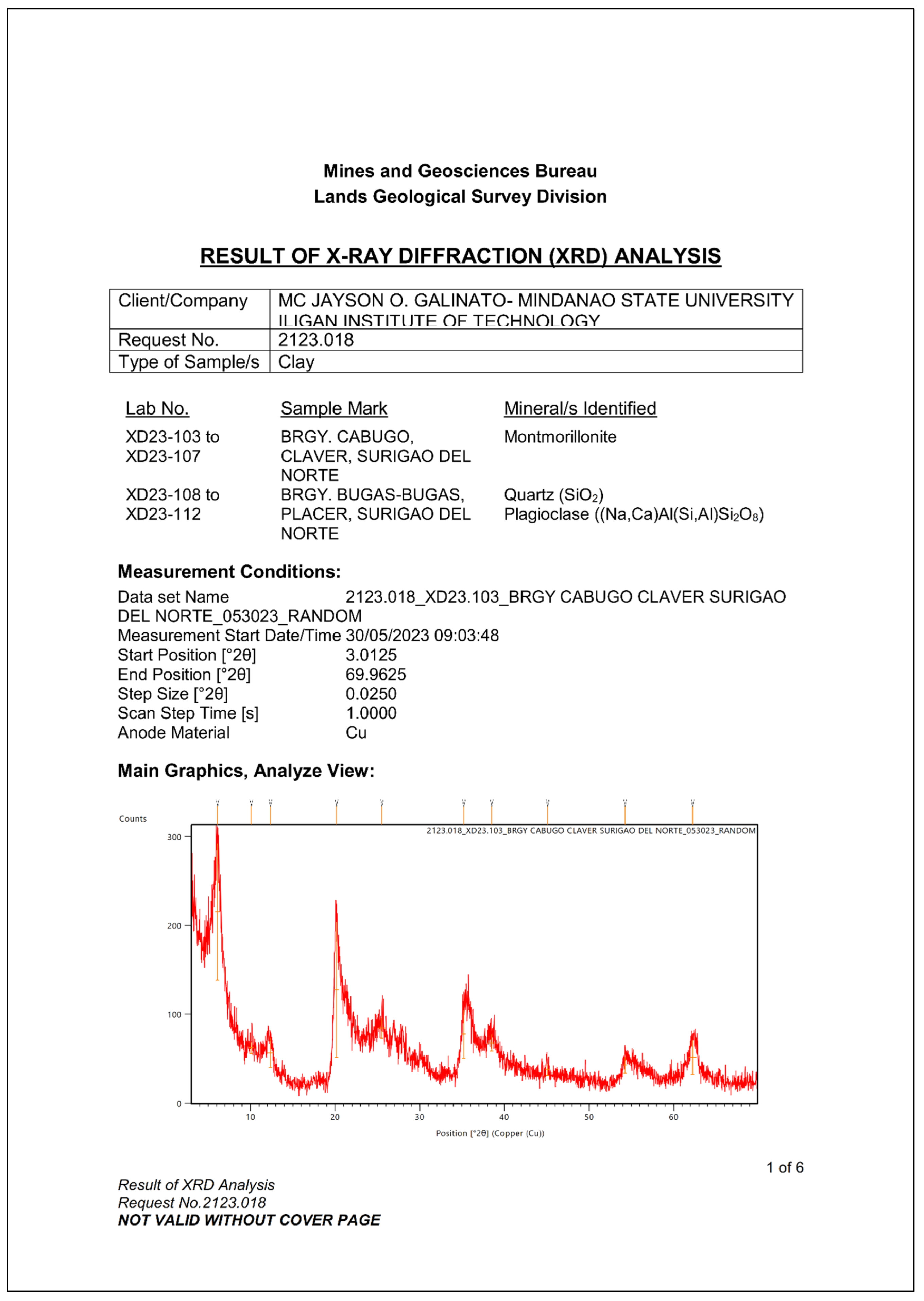
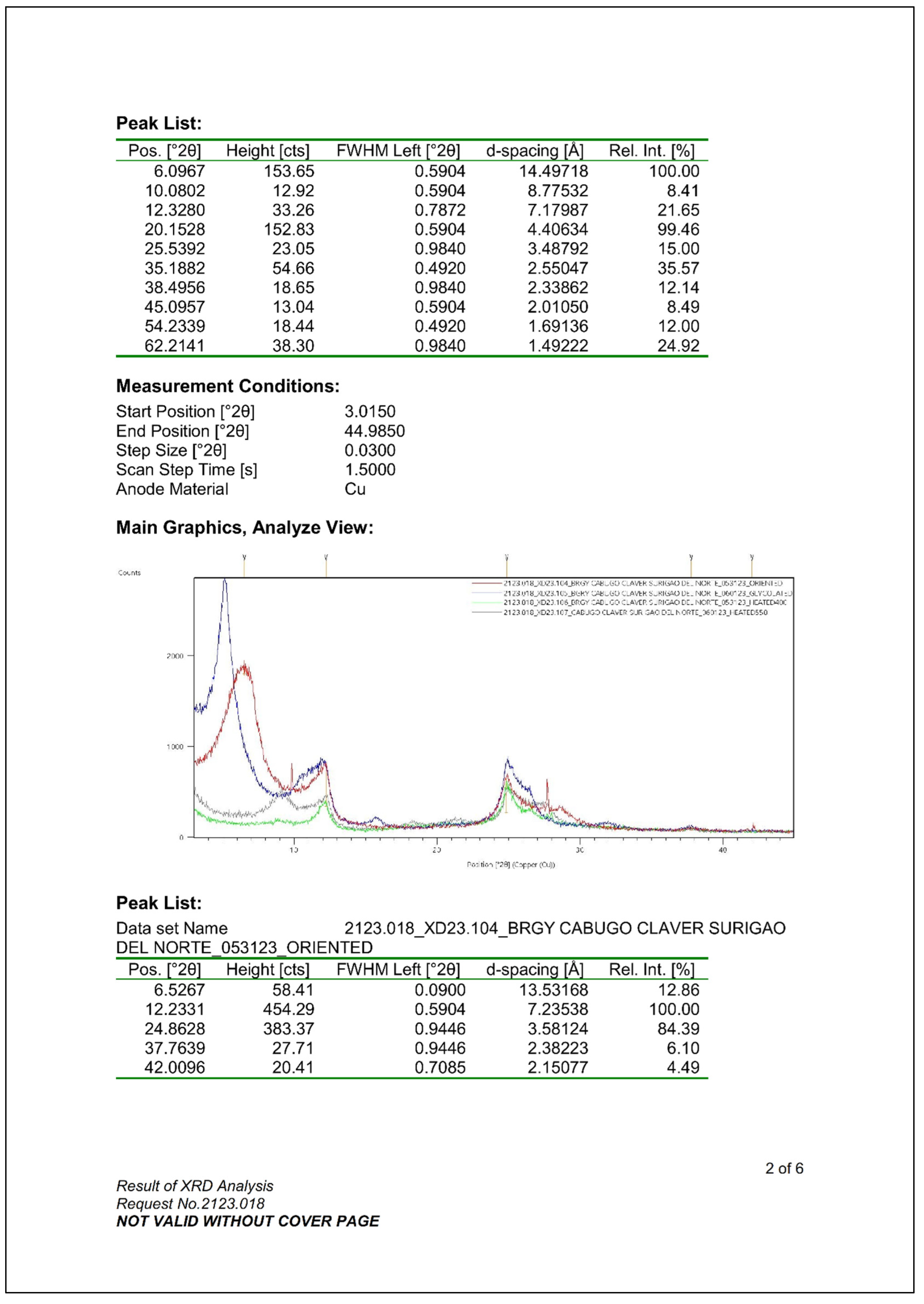
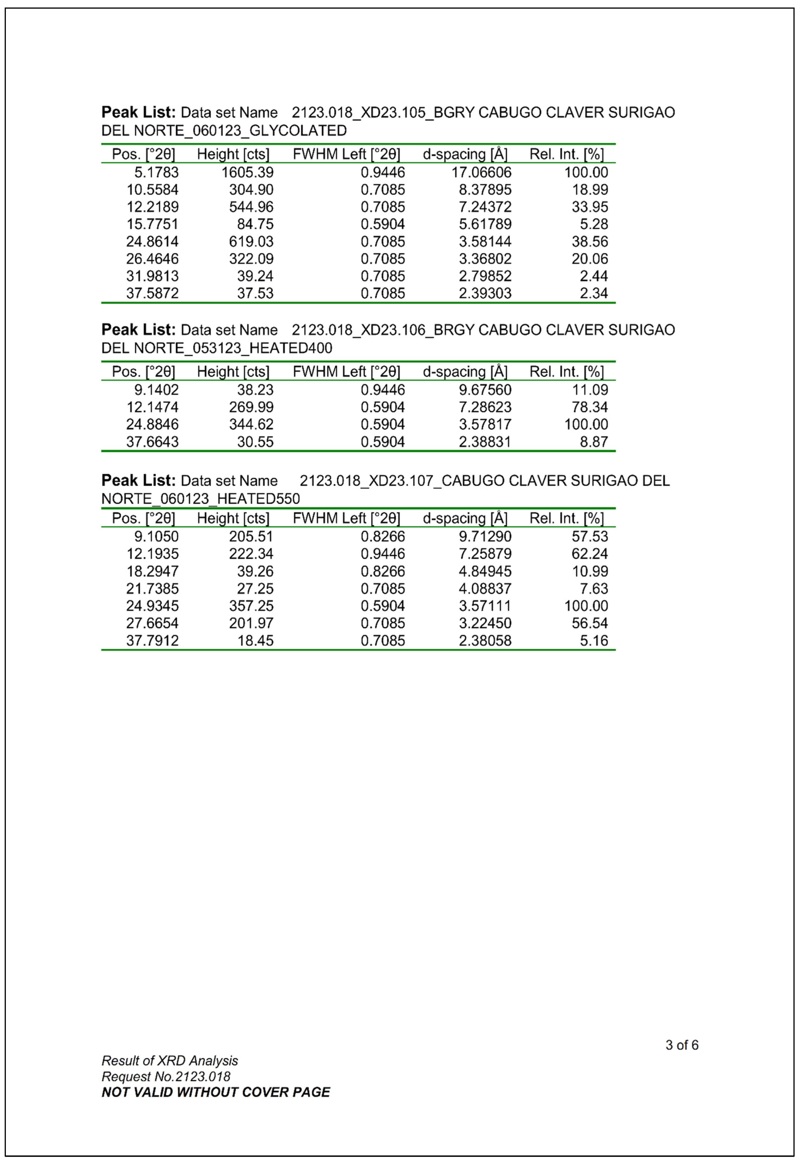
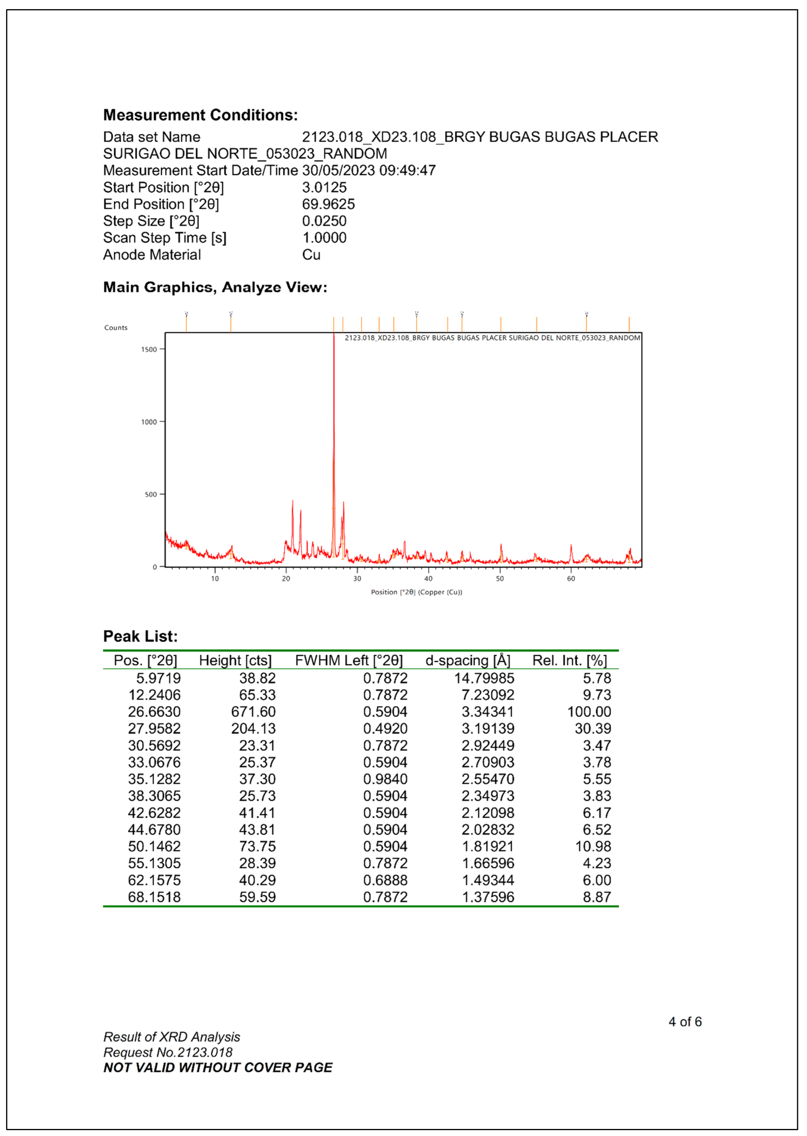
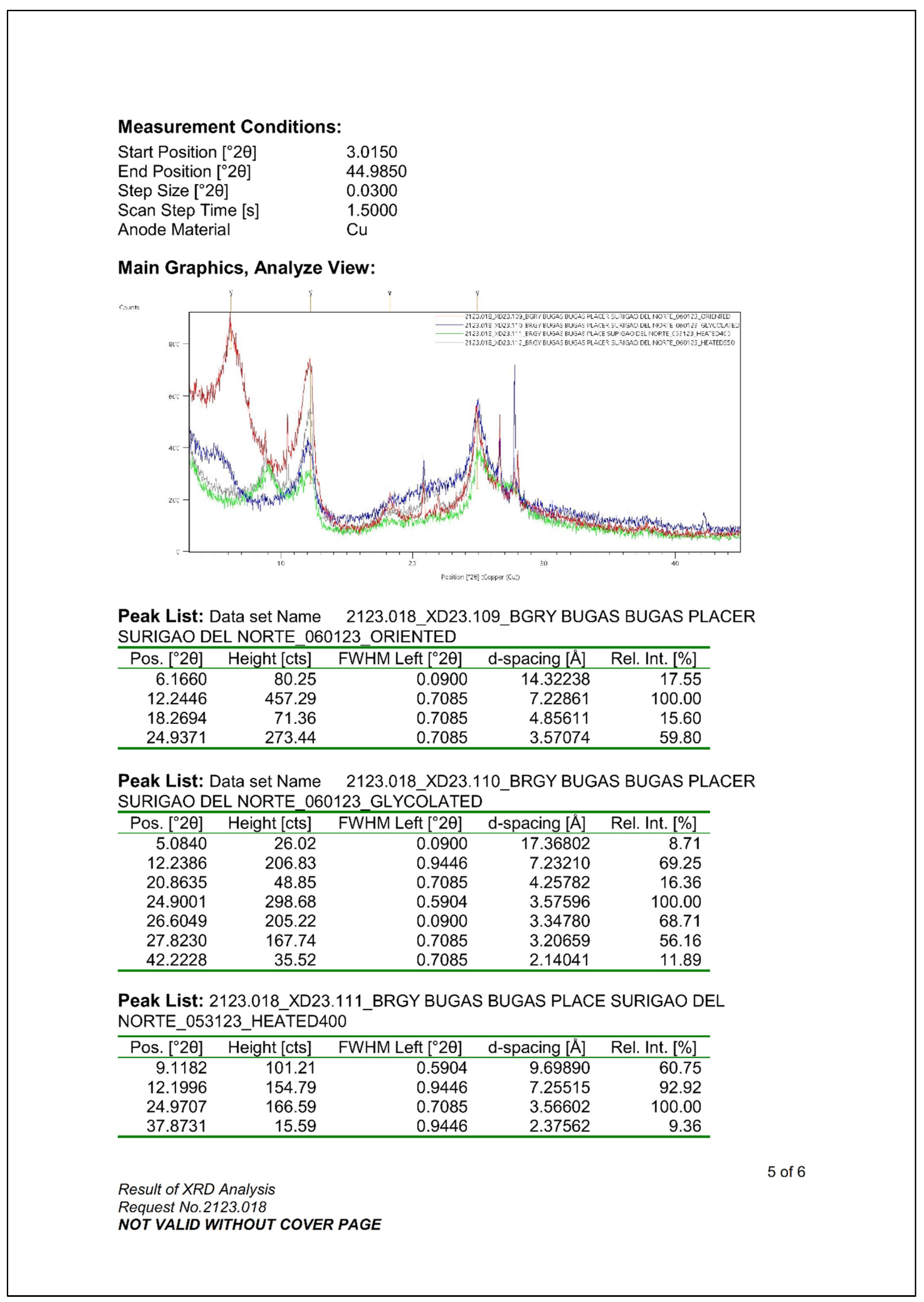
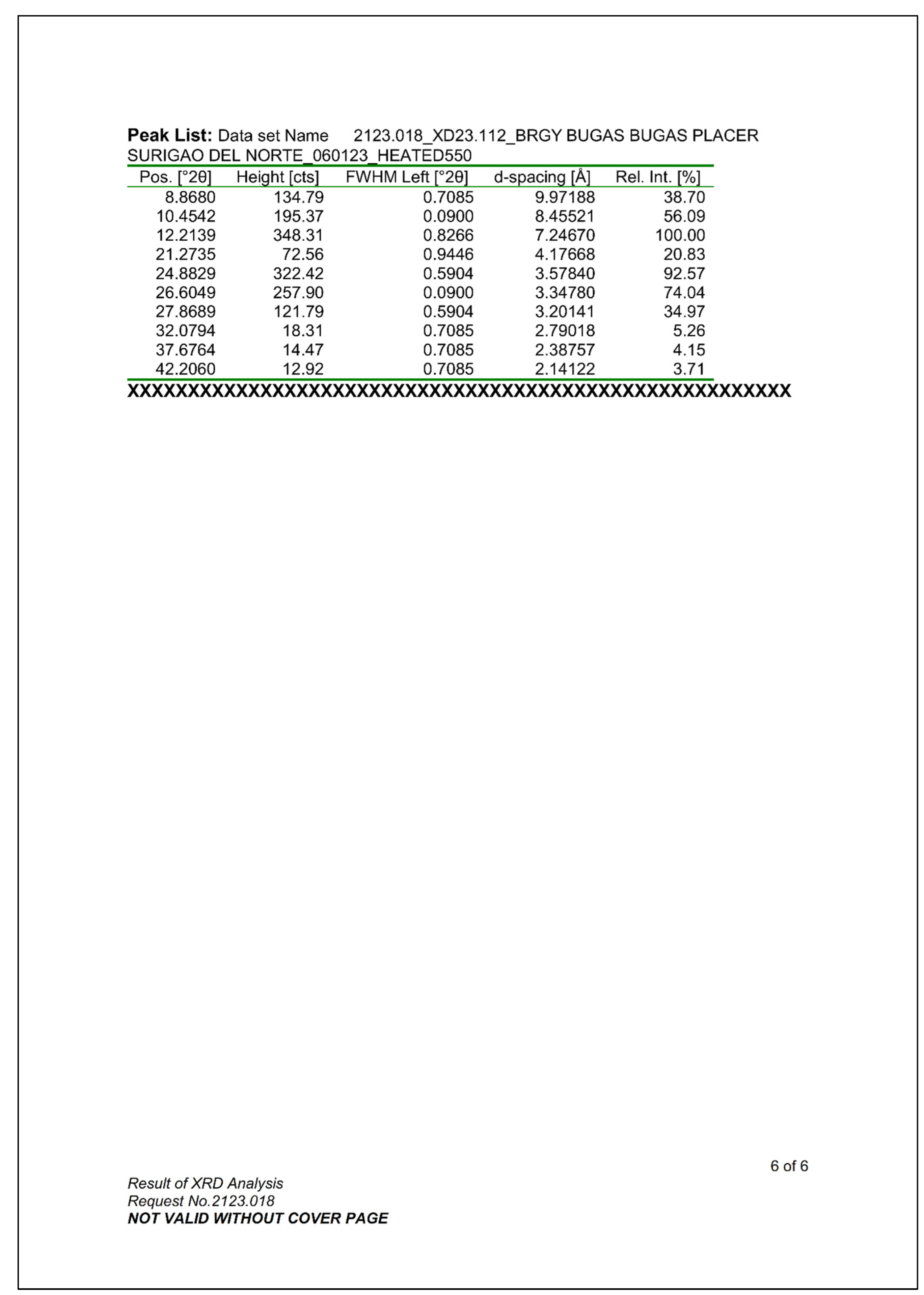
Appendix F. (GPS Spatial Data)
| Claver | Elevation (m) | Coordinates |
| A | 16 | N09° 32.749’, E125° 45.729’ |
| B | 14 | N09° 32.754’, E125° 45.726’ |
| C | 14 | N09° 32.755’, E125° 45.733’ |
| D | 14 | N09° 32.758’, E125° 45.725’ |
| E | 14 | N09° 32.759’, E125° 45.732’ |
| F | 14 | N09° 32.764’, E125° 45.729’ |
| G | 14 | N09° 32.767’, E125° 45.737’ |
| H | 14 | N09° 32.771’, E125° 45.728’ |
| I | 14 | N09° 32.771’, E125° 45.738’ |
| J | 14 | N09° 32.778’, E125° 45.728’ |
| Placer | Elevation (m) | Coordinates |
| 1 | 74 | N09° 39.321’, E125° 34.300’ |
| 2 | 74 | N09° 39.325’, E125° 34.307’ |
| 3 | 74 | N09° 39.322, E125° 34.307’ |
| 4 | 74 | N09° 39.321’, E125° 34.311’ |
| 5 | 74 | N09° 39.319’, E125° 34.311’ |
| 6 | 74 | N09° 39.317’, E125° 34.313’ |
| 7 | 74 | N09° 39.314’, E125° 34.314’ |
| 8 | 74 | N09° 39.317’, E125° 34.322’ |
| 9 | 72 | N09° 39.311’, E125° 34.320’ |
| 10 | 68 | N09° 39.312’, E125° 34.324’ |
Appendix G. (Sample Classification According to Flexural Strength and Water Absorption)
Sample classification according to flexural strength and water absorption
| Ceramic Peace | Flexural strength (kgf/cm2) | Water Absorption (%) |
| Indicated Values | Indicated Values | |
| Not Classified | ||
| Massive Bricks | ||
| Ceramic Bricks | ||
| Roof Tiles |
References
- Singh, N. B. (2022). Clays and clay minerals in the construction industry. MDPI. Available online: https://www.mdpi.com.
- Shahrokh, V., Khademi, H., Zeraatpisheh, M.(2023). Mapping clay mineral types using easily accessible data and machine learning techniques in a scarce data region: A case study in a semi-arid area in Iran. CATENA.
- Surveying & mapping. (n.d.). Available online: https://www.gps.gov.
- Philippine Mineral Reporting Code 2020. PMRCC. (2021, November 21). Available online: https://www.pmrcc.org.ph/resources/cc91813e-79d7-4d8c-8d88-e9909cec6353.
- Moreno-Maroto, J. M., & Alonso-Azcárate, J. (2018, April 24). What is Clay? A new definition of “clay” based on plasticity and its impact on the most widespread Soil Classification Systems. Applied Clay Science. Available online: https://www.sciencedirect.com.
- Kumari, N., & Mohan, C. (2021). Basics of clay minerals and their characteristic properties. IntechOpen. Available online: https://www.intechopen.com.
- Dondi, M. & Bertolotti, G.P. (2021). Basic Guidelines for Prospecting and Technological Assessment of Clays for the Ceramic Industry, Part 1. Interceram - International Ceramic Review. 70. 36-46. 10.1007/s42411-021-0472-x. [CrossRef]
- Sharma, R.P., Singh, S.S., Singh, S.K. (2019). Significance of clay minerals in development of alluvial soils of Aravalli range. Indian Journal of Geo Marine Sciences Vol. 48 (11), pp. 1783-1795. Available online: https://www.researchgate.net.
- Ouahabi, M.E., Ferrari, A.H., Fagel, N.(2017). Lacustrine clay mineral assemblages as a proxy for land-use and climate changes over the last 4 kyr: The Amik Lake case study, Southern Turkey. Quaternary International. [CrossRef]
- Ai Mi, N.V., Thongchart, & S., Mairaing, W.(2023). GEOLOGICAL AND GEOTECHNICAL PROPERTIES OF MEKONG DELTA CLAY AS COMPARISON WITH BANGKOK CLAY. International Journal of GEOMATE, Vol.24, Issue 101, pp.22-32.
- International Reporting Template. Crirsco. (2024). Available online: https://crirsco.com/the-international-reporting-template/.
- Harraz, H.Z.(2010). The Mining Cycle. Tanta University.
- IM Standing Committee on Reserve Definitions. (2014). CIM Definition Standards for Mineral Resources & Mineral Reserves: Inferred Mineral Resource. Canadian Institute of Mining, Metallurgy and Petroleum. Available online: https://mrmr.cim.org.
- Dondi, M. & Bertolotti, G.P. (2022). Basic guidelines for prospecting and technological assessment of clays for the ceramic industry. Part 2. Interceram-International Ceramic Review, 71(1), 28-37. [CrossRef]
- Chon, N. Q. (n.d.). Soil sampling guidelines - eurofins scientific. SOIL SAMPLING GUIDELINES. Available online: https://cdnmedia.eurofins.com.
- Yunta Mezquita, F., Van Liedekerke, M., Fernandez Ugalde, O., Németh, T., Balázs, R.B., Keresztes, M.A., Weiszburg, T., Rábl, E., Királyné Tóth, J., Gazsi, Z., Kovács, I., Ruiz Garcia, A.I., Cuevas, J., Van Eynde, E., Wojda, P., Panagos, P. and Jones, A.(2024). Clay mineral inventory in soils of Europe based on LUCAS survey soil samples. Publications Office of the European Union, Luxembourg. JRC136950. [CrossRef]
- Gillott, J. E. (2018). Some clay-related problems in engineering geology in North America: Clay minerals. Cambridge Core. Available online: https://www.cambridge.org.
- Chen, F. H. (2012). Foundations on expansive soils. Google Books. Available online: https://www.google.com.ph.
- Official Website: Surigao del Norte Province.(2024). Geography. Republic of the Philippines: Province of Surigao del Norte. Available online: https://surigaodelnorte.gov.ph.
- Panamaldeniya, L. (2021). Timely importance of GIS, GPS and RS. ResearchGate. Available online: https://www.researchgate.net.
- Land Surveying and GPS. E-education. (n.d.). Available online: https://www.e-education.psu.edu.
- Gao, J. (2002). Integration of GPS with Remote Sensing and GIs: Reality and Prospect. Photogrammetric Engineering & Remote Sensing, 68(5), 447–453.
- Jiang, S. Jiang, S. and Zhao, Bao.(2023). Application Analysis of GPS Surveying and Mapping Technology in Engineering Surveying and Mapping. Journal of Theory and Practice of Engineering Science 3(11):7-13.
- Canbaz, O. Canbaz, O., Gürsoy, Ö., & Gökce, A. (2018). Detecting Clay Minerals in Hydrothermal Alteration Areas with Integration of ASTER Image and Spectral Data in Kösedag-Zara (Sivas), Turkey. Journal of the Geological Society of India, 91(4), 483–488.
- Thin, L. N., Ting, L. Y., Husna, N. A., & Husin, M. H. (2016). GPS systems literature: inaccuracy factors and effective solutions. Int. J. Comput. Netw. Commun, 8(2), 123-131.
- Idris, A. N., Suldi, A. M., Hamid, J. R. A., & Sathyamoorthy, D. (2013). Effect of radio frequency interference (RFI) on the Global Positioning System (GPS) signals. IEEE 9th International Colloquium on Signal Processing and Its Applications.
- August, P., Michaud, J., Labash, C., & Smith, C. (n.d.). GPS for environmental applications: Accuracy and precision of locational data ... - ASPRS. Available online: https://www.asprs.org.
- What is remote sensing and what is it used for? USGS Science for a Changing World. (n.d.). Available online: https://www.usgs.gov.
- Babakan, S. & Oskouei, M. (2014). Integrated use of multispectral remote sensing and GIS for primary gold favorability mapping in Lahroud Region (NW Iran). Journal of Tethys. 2. 228-241.
- Shendi, El-Arabi. (2020). Vertical electrical sounding in the investigation of subsurface gravel deposits in arid environments—a case study, El-Salhayia plain, West Ismailia area, Egypt. Arabian Journal of Geosciences. 13. 10.1007/s12517-020-05877-8.
- Omer, I. K. (2021). Gravity Method. ResearchGate. Available online: https://www.researchgate.net.
- Mariita, N.O. (2007). The Magnetic Method. Available online: https://orkustofnun.is.
- Electromagnetic Induction (EM) Surveys. Forest Environmental Services, Inc. (n.d.). Available online: http://www.fesinc.net.
- Mutter, J., & Lerner-Lam, A. (2020). Seismology. AccessScience.
- Soller, D. R. (2004). Introduction to Geologic Mapping. U.S. Geological Survey. Available online: https://www.usgs.gov.
- Petrology & Mineralogy. Geological Sciences. (2018). Available online: https://www.colorado.edu.
- A Brief Introduction on Thin Section Preparation. National Petrographic Service. (n.d.). Available online: http://www.nationalpetrographic.com.
- Gatiboni, L. 2022. Soils and Plant Nutrients, Chapter 1. In: K.A. Moore, and. L.K. Bradley (eds). North Carolina Extension Gardener Handbook, 2nd ed. NC State Extension, Raleigh, NC. Available online: https://content.ces.ncsu.edu.
- Harbitz, A.(2019). A zigzag survey design for continuous transect sampling with guaranteed equal coverage probability. Fisheries and Research.
- Pham. T.N., Acharya, P., Bachina, S., Osterloh, K., Nguyen, K.D.(2023). Deep-Learning Framework for Optimal Selection of Soil Sampling Sites. Available online: https://www.researchgate.net/.
- Food and agriculture organization of the united nations.(2015). World reference base for soil resources: International soil classification system for naming soils and creating legends for soil maps. WORLD SOIL RESOURCES REPORTS. Available online: https://www.fao.org.
- ASTM C326. (2018). Standard test method for drying and firing shrinkages of ceramic Whiteware clays. ASTM International - Standards Worldwide. Available online: https://www.astm.org.
- Tiongson, JM., Adajar, M.A.Q. (2020). Compaction Characteristics of a Fine-Grained Soil Potential for Landfill Liner Application. International Journal of GEOMATE, Vol.19, Issue 71, pp. 211 - 218.
- Bouh, H.A.(2020). X-Ray fluorescence Technique Analysis (Principles and instrumentations). Muruz. Available online: https://www.researchgate.net.
- Bunaciu, A.A., Udriştioiu, E.G., & Aboul-Enein, H.Y (2015). X-Ray Diffraction: Instrumentation and Applications. Critical Reviews in Analytical Chemistry, 45:4, 289-299.
- Rajapakse, R.(2016). Soil Laboratory Testing. Geotechnical Engineering Calculations and Rules of Thumb (Second Edition), Pages 47-60.
- ASTM D4318.(2018). Standard test methods for liquid limit, plastic limit, and plasticity index of Soils. ASTM International - Standards Worldwide. Available online: https://www.astm.org.
- Hobbs, P.R.N. Hobbs, P.R.N., Jones, L.D., Kirkham, M.P., Gunn, & D.A., Entwisle, D.C.(2018). Shrinkage limit test results and interpretation for clay soils. Quarterly Journal of Engineering Geology and Hydrogeology, Volume 52, Pages 220 - 229.
- Hoogsteen, M.J.J., Lantinga, E.A., Bakker, & E.J., Tittonell, P.A.(2018). An Evaluation of the Loss-on-Ignition Method for Determining the Soil Organic Matter Content of Calcareous Soils. Communications In Soil Science and Plant Analysis.
- ASTM C373.(2014). Standard test method for water absorption, bulk density, apparent porosity, and apparent specific gravity of fired Whiteware products. ASTM International - Standards Worldwide. Available online: https://www.astm.org.
- Kramarenko, V.V., Nikitenkov, A.N., Matveenko, I.A., Molokov, V.Y., & Vasilenko, Y.S.(2016). Determination of water content in clay and organic soil using microwave oven. IOP Conference Series: Earth and Environmental Science, Volume 43, XX International Scientific Symposium of Students, Postgraduates and Young Scientists on “Problems of Geology and Subsurface Development”. [CrossRef]
- XRite Inc.(2025). A Guide to Understanding Color Communication: Part 3. X-Rite Inc. h. Available online: https://www.pac.gr.
- ASTM C1161. (2023). Standard test method for flexural strength of advanced ceramics at ambient temperature. ASTM International - Standards Worldwide. Available online: https://www.astm.org.
- Mylan, R., Maharaj, C., Maharaj, R.(2017). Creating the Optimal Product Formula for use by A Heavy Clay BlockManufacturer. Clay Research, Vol. 35, No. 2, pp. 71-83. Available online: https://www.researchgate.net.
- Kohut, W. (1986). Process for preparing a clay slurry. Available online: https://patents.google.com.
- Cáceres, J. R., Pineda-Rodríguez, J. R., & Rojas-Suárez, J. P. (2021). Analysis of the ratio between the plasticity of clay and the expansion capacity by changes in humidity and temperature. Journal of Physics: Conference Series, 2139(1), 012010.
- Alam, T. (n.d.). Composition of Bricks - Function of Ingredients. Civil Engineering. Available online: https://civiltoday.com.
- Torres, A., Basto, R., Chaparro, A., & Sánchez, Jorge. (2019). Physicochemical and mineralogical properties of clays used in ceramic industry at North East Colombia. Available online: https://www.researchgate.net.
- Teixeira, Silvio & Souza, S. & Nobre, M.. (2004). Physical and Mechanical Properties of ceramics from Clays of the West Region of São Paulo State-Brazil. Cerâmica. 50. 10.1590/S0366-69132004000300015.
- Yami, A. & Umaru, S. (2007). Characterization of Some Nigerian Clays as Refractory Materials for Furnace Lining. Continental Journal of Engineering Sciences. Vol. 2.. Pp. 30-35. Available online: https://www.researchgate.net.
- Bin, X., Li. X., Lu, J.(2022). Effect of Clay Mineralogy and Soil Organic Carbon in Aggregates under Straw Incorporation. Agronomy.
- Ndjigui, P.-D., Mbey, J. A., Fadil-Djenabou, S., Onana, V. L., Bayiga, E. C., Enock Embom, C., & Ekosse, G.-I. (2021). Characteristics of kaolinitic raw materials from the Lokoundje River (Kribi, Cameroon) for ceramic applications. Applied Sciences, 11(13), 6118.
- Dong, Z., Sun, & Q., Zhang, W.(2021). Physical and Mechanical Properties of Clay After Heating in Different Oxygen Levels and Cooling With Different Methods. Research Square.
Disclaimer/Publisher’s Note: The statements, opinions and data contained in all publications are solely those of the individual author(s) and contributor(s) and not of MDPI and/or the editor(s). MDPI and/or the editor(s) disclaim responsibility for any injury to people or property resulting from any ideas, methods, instructions or products referred to in the content. |
© 2025 by the authors. Licensee MDPI, Basel, Switzerland. This article is an open access article distributed under the terms and conditions of the Creative Commons Attribution (CC BY) license (https://creativecommons.org/licenses/by/4.0/).
Copyright: This open access article is published under a Creative Commons CC BY 4.0 license, which permit the free download, distribution, and reuse, provided that the author and preprint are cited in any reuse.


