Submitted:
17 March 2025
Posted:
18 March 2025
You are already at the latest version
Abstract
To keep up with the times, speed is one of the features of the turbofan engine, and this means operating under harsh conditions of high temperature and pressure. This is why engine parts, especially the high pressure turbine blades (HPT- Bs), often suffer from damage due to high temperature, high pressure, foreign bodies (FOD) impact and other factors. This study aims to apply a new thermal barrier coating (TBC) to increase HPT-Bs service cycles, reduce replace and maintain cost so preserve natural resources for future generations. To achieve this, a thermal spray method was used to apply NiCrBSi (as bond coat) and Ni based reinforced with tungsten carbide (WC) (as top coat) as composite TBC system with thickness 200-300 ?m, onto nickel based alloy substrate under conditions selected using the Taguchi program. By the microstructure, micro-hardness, thermal cycling and hot erosion tests, the TBC layer performance was investigated. Moreover, results were studied and discussions using a SEM, Optical microscopy and XRD analysis.
Keywords:
flame thermal spray (FTHS)
; high pressure turbine blades
; nickel based alloy
; thermal barrier coating
; taguchi method
; thermal cycling test
; solid particle erosion (SPE)
1. Introduction
High operating temperature above 1000 ºC is necessary to increase advanced gas turbine engines efficiency, but at the same time thermo-mechanical stresses form in the rotor blades located in the first stage of high pressure turbine module because of high pressure and high temperature [1]. Generally, defects formed at the leading edge (LE), the trilling edge (TE), or the tip of the blade when exposed in service to thermal cycling and hot erosion especially in dusty environment. Figure 1 shown most defects that determine by visual inspection of HPT-B in the core of engine by borescope tool [2]. Selection ways and materials able to withstand in such these corrosive and harsh environments have prompted many theoretical and practical research studies to work on finding fundamental solutions to this issue [3,4].
Nickel based alloys are widely used in the aerospace engines industry to make turbine blades, discs and other hot section engine parts because their properties that meet the operating condition of the aircraft engine from temperature above the 900°C, rotational speed more than 10,000 RPM, average time (hr) between overhaul more than 10 000 hr, and an Oxidizing/Corrosive environment. Where Nickel based alloys consist of a FCC matrix γ-Ni with coherent intermetallic precipitates, carbides, borides, and other phases dispersed such as the gamma prime, γ′. Generally, different elements are adding for this alloys, such as, Cr and Al to increase oxidation resistance. Co, Mo, and W improve the strength at great temperatures. C provide creep strength. Inconel 718 is one of these alloys has been extensively used as gas turbine blades due to its excellent thermal-mechanical performance. To increase performance reliability and durability of the nickel-based alloys in harsh environment, a thermal barrier coating (TBC) is usually applied to avoid the blade damage [5].
Generally, a typical TBC system have thicknesses arrange between 100 and 500 µm is consisting two layers of a topcoat (TC) made of ceramic or composite materials and a bond coat (BC) made of metallic materials. TBCs can be deposits by wide range of techniques such as EB-PVD, thermal spray techniques (e.g. HVOF, APS, FTHS…etc.) [6,7,8,9,10,11,12].
Flame thermal spraying (FTHS) is an effective surface engineering technology that can improve the wear, corrosion, and fatigue resistance in ceramic, metals, polymers components. It applied as a new coating or repair of damage parts. In FTHS insert the feedstock coating materials (powder or wire) in a combustion area (flame, plasma, arc) where it is melted, after that compress air atomize it through nozzle toward substrate surface as illustrated in Figure 2 [10,13]. Although the microstructure of this technique have low bond and more porosity than other techniques. It is considered easy, cost effective, and widely use in industrial applications, also improve adhesion and reduce porosity can achieve by proper design of experiment (DOE). Many researcher use DOE approaches such as Taguchi method which consider an important optimization process that can provide high quality coatings with fewer experiments [14,15].
Choudhary et al. [16] reported ceramic coating materials like YSZ although its provide high thermal barrier coating properties in harsh environments, it is still appearing mismatch with substrate. Rachidi et al. [17] showed that composite TBCs applied by FTHS offered good abrasive performances, due to hardness of carbides, and toughness of metal base. Fanicchia et al. [10] FTHS appeared 80% increase in thermal cycling lifetime when compare with APS process, due to strain performance of the applied TBCs.
Also, TBC of a HPT-Bs must have good hot erosion resistance in commercial or military A/C engines. Most turbine blades suffer from erosion due to the collision of solid particles in dusty environments during take-off or when the aircraft is close to land. Several studies refer that durability of TBC in aero-engines can determine by solid particle erosion (SPE) as one of the major life-limiting phenomenon [18,19,20,21,22,23,24]. Cernuschi et al. [25] have studied the effect of impact angle on the behavior of APS TBC and EB-PVD TBC under erosion at 700 ºC. Michael J. et al. [26] performed SPE of YSZ at high temperature to study the effect of particle kinetic energy, impact angle, and temperature on erosion rate of TBCs, using alumina as erodent particles.
The aim of this study is to verify if the applied the metallic powder NiCrBSi as bond coat and composite coating Ni based-WC as top coat by FTHS process, using 9 runs depending on Taguchi approach can provide effective TBC layer. Furthermore, micro-hardness, thermal cycling test, solid particle erosion test of as-sprayed thermal barrier coating were study and results were analyzed by SEM micrographs, energy dispersive X-rays spectrometry (EDS), and X-ray diffraction (XRD).
2. Materials and Methods
2.1. Materials:
The experimental samples were consisted of flat Inconel 718 samples (1 × 1× 0.04) cm. First, the samples were sandblasted by using fine silicon carbide in order to increase the roughness of the surface. Secondly, the specimens cleaned with isopropanol in an ultrasonic bath. Finally, Appling the two coating layers using thermal spray process. Starting from the substrate material, the first layer is the bonding coat (NiCrBSi) called 10009 Eut-alloy consist a particles size (20-97.2) µm, followed by the toping coat layer (Ni based-WC) called 10112 Eutalloy consist a particles size (42.86-93.31) µm. The chemical composition of the materials is shown in Table 1.
2.2. Flame thermal Spray Process (FTHS):
Flame thermal spray deposition was performed using a 0.5 bar oxygen and 0.7 bar acetylene was carried out by Super Jet Eutalloy (Super Jet Eutalloy, Castolin Eutectic) torch, as shown in Figure 2. To produce high-quality coatings experiments of design (DOE) were designed as per Taguchi's L9 (3**3) orthogonal array and tests were conducted with different standoff distance (mm), transverse velocity (mm/min), and feeding rate (g/min), as shown in Table 2. Uncoated and coated samples shown in Figure 3 [27].
2.3. Optical, Microstructural, Thermal and Mechanical Tests:
The thickness and diffusion depth of TBCs of nine samples where measured by Optical microscopy and taken at 40X magnification (using Meiji Techno Microscopes). A detailed analysis of phases and their composition was made before and after coating by XRD (using Shimadzu XRD-6000). The XRD diffractograms were smoothed and analyzed with Xpert HighScore Plus (Panalytical Technologies Pvt. Ltd, Netherlands) software [28]. The voltage and the current were 40 kV and 100 mA respectively. The diffraction angle 2θ was between 20° and 80°. SEM with EDX were used to identifying the surface morphology of the coated samples at various magnifications, and studying the porosity and interface area (using Thermo Scientific™ Axia ChemiSEM™).
Microhardness test for uncoated and coated three samples was done by means of Vickers microhardness (using HVS-1000 Digital Micro hardness tester), the load used in this test was 9.8 N and the time of holding was 15 sec. Three readings of each sample were measurement, and the average of those measurements indicates the hardness value [29].
To evaluate the thermal shock performance of TBCs, a three samples with different thickness (200, 250, 300) μm have dimensions (1 × 1 × 0.04) cm were used in this test to measured how strong the bond between the TBCs and the substrate by heating samples to 1100°C for 25 min in a furnace, followed by cooling in water for 10 S at ambient temperature then sample dried as shown in Figure 4. The weight of the samples was measured after each cycle. The thermal shock test was terminated when observed signs of failure in the TBC. Removing more than 10% of TBC material from substrate in this test that detect by visual inspection test considered failure. At the end the effect of thermal cycling test on the microstructure of TBC was study by a scanning-electron microscope (SEM) [30,31].
Moreover, using locally manufacture SPE unit in Ministry of Industry and Minerals/General Company for Steel Industries by following ASTM G76 standard, Figure 5a. Test was carried out from room temperature up to 1050 °C [32,33,34]. The particle impingement angle is controlled via the specimen holder's orientation, at 30°, 60° and 90°, SoD was kept constant at a 150-mm during test. Referring to SEM image in Figure 5b, irregularly shaped Silica powder with particles size approximately ranged between (160-430) µm were used as the erodent material, feeding rate 10 g/min. Samples weights pre- and post-test were measured, a total duration period of SPE test was 20 min. Post-test surface morphology and cross section examination was conducted using SEM to analysis and discussion test results.
3. Results and Discussion
Depending on experimental plan of Taguchi 9 runs is followed for the test and outcomes obtained are tabulated for the various combinations of flame thermal spray parameters as shown in Table 3.
Where Trial 1, Trail 2, and Trail 3 are diffusion depth in mm, and equation of single to noise ratio used in this study is larger is better:
Where Y is a response variable (the diffusion depth) and n is the experiment number repetitions. The results as appear in Table 3 that higher diffusion was obtained in the trail3 (i.e. standoff distance (150 mm), transverse velocity (100 mm/min), and feeding rate (30 g/min).
Response table of signal to noise ratio (S/N) was used to indicate which major parameter need control and which do not, that to achieve high quality TBCs, where the parameter with the greatest difference in delta value (the delta value is the difference between the largest average S/N and the lowest average S/N for each parameter) between all FTHS parameters has the biggest effect on the response as shown in Table 4.
Depending on Table 4, The standoff distance (A) had the highest delta value 1.76, and thus it is the most significant parameter affecting the coating diffusion (Rank 1), while the transverse velocity (B) has the least effect with delta value 1.04 (Rank 3). According to data mentioned in Table 3 and Table 4 can describe the main effect plot for means that made by Minitab 18 software, as illustrated in Figure 6.
It can be arrived that the optimal condition for diffusion is the combination of A3, B3, and C3. for parameters A, B, and C, the increase of TBCs quality is observed when changing the level from 1 to 3. The depth of diffusion improves by more than 10 μm as the SoD increases from 125 to 150 mm, and by approximately 8 μm as feeding rate increase from 20 to 30 g/min. Also, the diffusion increase by more than 6 μm as the T. velocity increases from 100 to 300 mm/min.
ANOVA (Analysis of Variance) is the statistical treated most commonly executed to study the results of the experiment to appears the contribution effect of each factor[tag4], as illustrated in Table 5. Therefore, based on the S/N ratio and ANOVA analyses, the optimum conditions are the spray distance at level 3, the transvers velocity at level 3, and the powder feeding at level 3. What this means is, as this selected distance between nozzle and substrate, Transvers velocity, and powder feeding allow for both the temperature and speed of shooted coating materials particles to produce high volume fraction of melted coating powders and reduce oxidation products, therefore dense TBCs layers form. So, a TBCs with higher quality will be produced, which is same to the results that mentioned in other studies [35,36].
From Table 6, it is evident that experiments outcomes 1, 2, and 3 provided a diffusion efficiency of 98.6%, 98.7%, and 99%, which is obviously closer to the predicted efficiency determined via Minitab18 software using the Taguchi optimization method. All tests and assessments conducted in this work were applied to the samples in the third experiment, which had a deposition efficiency of roughly 99%.
Samples and Cross section of sample after FTHS was represent in Figure 7a,b which illustrate the shape and size of the diffusion area. Where a typical TBC layers formed, having both an interdiffusion zone (IDZ) and an outer layer. The thickness and diffusion depth of the obtained TBCs coating were measured by means of optical microscopy (40 X magnification), the average thickness of result coatings was about 200-300 µm.
Figure 8 presents chemical composition of TBCs according to EDS analysis along with the typical morphology of the surface and cross section of the TBCs as deposited composite coating–IN718 as substrate depending on optimized spraying condition selected by DOE. It is evident that the layers are deposited on the substrate continuously without interruption and without the presence of micro and macro cracks on the interface, shown in Figure 8a. The layers are very dense and homogeneous microstructure have aspherical particles with size range (300nm-1.6µm), that indicated to completing melting process for almost all coating materials and stacked on substrate in homogeneous manner and porosity less than 4% (Figure 8b). The EDS analysis in Figure 8c (showing wt.% of each element) indicates the presence of all coating elements as Ni, Cr, C, Fe, W and Si, except B element absent in this test but it appears later in XRD results.
The XRD pattern in Figure 9a,b revealed that the coating consists mainly same phases that revealed in raw materials but with more intensity with better distribution on substrate. As spray TBCs layer formed on substrate consisted mainly of The structure of the primary solid solution γ - Ni along with intermetallic compounds, carbides, and borides phases. Most these phases provide high hardness such as; carbides e.g. WC, Cr23C6 as mainly amount and W2C, and Cr7C3 in minor amount. Along with borides phases such as Ni3B, CrB. Moreover, intermetallic compounds such as Ni3Al, Ni3Nb, and Ni3Si cause in increase strength, oxidation and creep resistance of Ni matrix with increasing the temperature [37,38]. Most these results were common for NiCrBSi and Ni based-WC scales prepared by other thermal spraying methods (such as APS, HVOF), and laser coating [39,40].
Microhardness testing was executed on samples before and after coating. the results in Figure 10 showed that the hardness of the IN718 sample was around 210 HV while the hardness of IN718 sample with TBC was 940 HV. This increase in surface hardness is related to the dense coherent deposited layer on substrate which contain on hard particles of carbides mainly from WC particles, and borides that distributed homogenously by FTHS due to optimum spray conditions chosen by taguchi method [17,40].
In thermal shock test used three samples, test was stopped once the TBC had spalled from the sample. Thermal traces of the cycles for three samples are shown in Figure 11. In a manner similar to results reported in TBC system by Mengchuan Shi et al. [41], the results in Figure 11a,b have indicated there are a linear increase in pall off percentage and weight loss as the cycle number increased. The beginnings of damage in all samples have occurred around the 100 cycle. At 600 cycles, the sample with thickness 300µm exhibited an approximately 1% failure, and the sample with thickness 250µm exhibited an approximately 5% failure, while the sample with thickness 200µm exhibited a 9.6% failure, which is close to the 10% threshold for the TBC failure criteria.
Previous studies have indicated that damage and failure of TBC were attributed to the combined factors of thermal stress, due to heating and cooling cycle cause to thermal gradient between TBC and substrate, and the harmly thermally grown oxides (TGO), these factors combined lead to initiate and propagate of cracks in the TC then peel off of the coating [42]. Since, tensile stress generates in BC/substrate during the heating cycle and compressive stress generate in the TC layer, and vice versa in cooling cycle [16].
Figure 11c, the failure mechanism of thermal shock tested, conducted with a sample subjected to 600 cycles, revealed that the spallation of the topcoat TBCs was mainly located at the edges. This phenomenon is interpolated to the what known edge effect, where normally thermal stress is concentrated at sharp edges, this effect was similar to the findings of Pourbafrani et al. [43].
After thermal cycling test the microstructure of cross-sections of the TBCs analysis by SEM to identified locations of coating failure within the samples, as appear in Figure 12. Thermal cycling test results of TBC with difference thickness indicated that the thermal cyclic lifetime of TBCs decreased with the increase in TGO thickness [44]. At high temperature, harmful thermal growth oxide layer formed by oxidation of the NiCrAlY cause in forming thermal stress at the interface of TC/TGO then to spallation and failure the top layer of coating [45]. But by using Ni based-WC as TC which contain phases like Ni3Al, Ni3Si and Cr7C3 can increase oxidation resistance of TBC, then limit oxide scale [37,46,47,48]. So, the best longevity thermal shock resistance was observed in the TBC with thickness 300 µm is about 89% greater than the sample with thickness 200µm, with increasing the TBC thickness, TGO thickness has decreased. Research study of Ashofteh A. et al [49] supported this conclusion, too.
Results of this test in this study obvious the average thermal shock life is about 600 cycles under 1100 °C (heating 25min/cycle) when use the optimized NiCrBSi (BC) and Ni based-WC (TC) as TBC system. In experiments from the work of Pourbafrani et al, [43] the peeling off area was extended to more than 20% of the noncommercial 7YSZ TBC area after 450 cycles under 1100 °C (heating 10min/cycle). Zhao Y. et al. [50] found that the 8YSZ TBCs had a lifetime of 166 cycles under 1100 °C (heating 30min/cycle). Therefore, these results indicated that the optimized NiCrBSi (BC) and Ni based-WC (TC) as TBC had a desirable thermal shock resistance and thermal shock life due to metal-ceramic composite TBC have less mismatch with substrate when compare with ceramic TBC.
SPE test results are presented in Figure 13 which demonstrates the effect of the impingement angle on the sample mass loss by erode material. They are indicating that the sample erosion rate increases linearly with increase impact angle from 30° to 90°. At 30° sample exhibited 0.45 g/kg erosion rate, at 60° an approximately 1.9 g/kg erosion rate, and at 90° erosion rate was 4.2 g/kg. This is attributed to the lower particle energy transferred to the coating for lower impingement angles, similar findings were reported by Satyapal M. et al. [51] and Dongyun S. et al. [52] where TBCs suffered less weight loss during erosion test under a lower impact angle.
As mention in literature, the group of phase composite TBCs appear much lower SPE rates than the group of ceramic TBCs. Because these materials with ionic and metallic bonds combined mode of erosion mechanism (i.e. ductile and brittle), which are flexible and non-directional bonds, contribute to increased toughness and rate of impact resistance with increasing temperature, thus leading to a reduced erosion rate at elevated temperature [32,53]. The erosion rate is defined as weight loss of eroded sample in g, to the mass of impacting particles in kg ratio [22].
Erosion rate, E = (weight loss of coating (g)) ⁄ (weight of erodent used (kg))
The SEM-EDS analysis provide useful information about the erosion mechanism in the TBC layers that done by silica particles with the irregular and sharp edges at high temperature (1050 °C). The eroded samples’ cross section profiles in Figure 14 indicated increase reduction in the thickness of TC layer is observed as impact angle increased, while the thickness of BC and substrate maintain same during the SPE test at all impact angles. In Figure 15 depend on SEM-EDS investigations, the micrograph of the TBC eroded surfaces indicates there are a craters, and lips/raised areas that are a result of a repeated impacting silica particles sliding along the areas that rich in Ni (ductile SPE mode). Moreover, micro- cracks, micro-cutting are still evident at the grooves (brittle SPE mode) due to WC, W2C, and other hard phases that confirmed previous in XRD investigate. Praveen et al [21] and Venkataramana et al [53] reported same observations in their studies. So, the combined ductile and brittle mode of solid particle erosion mechanism can have observed in TC when composite coating like NiCrBSi-WC applied as TC in this study.
4. Conclusions
According to chemical, morphology, microstructure, thermal, and mechanical properties investigation of deposition of NiCrBSi as bond coating (BC) and Ni based-WC as top coating (TC) on IN718 substrate by flame thermal spray, and apply DOE by taguchi method, it can possible reach to the following conclusions:
- Flame thermal spray process was successfully employed to deposit atypical BC, and TC layers as TBCs with thickness (200-300) µm on IN718 substrate that used for high temperature application such as HPT-Bs in aircraft engines.
- The matrix experiment under different flame spraying parameters confirmed that an improvement of the diffusion depth and good metallurgical bond of flame sprayed coatings can be made using the Taguchi method. The most influential parameter in the spray process was the SoD, followed by powder feeding rate, then the T. velocity.
- As for the optical microscope, SEM, and EDS tests of the surface and cross section, a typical cohesion dense TBC layers formed with spherical particles of varying sizes from (300 nm to 1.6 microns). This shows the completion of the melting process for most of the particles of the primary coating material and its spread and stacked on the surface in a homogeneous manner with minimal pores and micro cracks. Also, XRD informed that TBCs consists mainly of γ-Ni, carbides such as Cr7C3, Cr23C6, and WC, borides such as Ni3B, CrB, in addition to intermetallic compounds such as Ni3Si, Ni3Al, and Ni3Nb. These phases were distributed homogenously in the formed TBCs.
- The microhardness tests carried out on uncoated and coated samples demonstrate that the hardness increased more than 4 times due to the presence of WC hard ceramic particles in coating, in addition to uniform distribution of carbides and borides compounds in the microstructure of TBC by using FTHS process.
- Evaluation thermal cycling behavior of TBC with difference thickness (200, 250, and 300) µm done by using a furnace test at 1100 °C. Under heating 25min/ water cooling 10 sec/ cycle conditions the TBCs had a lifetime up to 600 cycle before spallation of TBC with thickness 200 µm reach 9,6% (10% failure criteria). In all cases, the failure modes of the TBC were segments partial spallation started from the coating edge. Best performance was observed for the coating with thickness 300 µm because increasing the thickness of TC layer and presence of γ-Ni, carbides such as Cr7C3, borides such as CrB, and intermetallic compounds such as Ni3Si, decreased the thickness of a harmly oxides layer that’s formed.
- The SPE test were run at elevated temperature (1050 °C), where silica with size (160-430) µm was use as erodent particles, the total erosion time was 20 min, with a particle feeding rate of 10 g/min. The erosion rate of a TBC was evaluated at 30°, 60°, and 90° impact angle. Results indicate that the flame thermal sprayed coating could protect the substrate at 30°, 60° and 90° impact angles. The coating shows a lower material removal rate by the erosion at an impact angle of 30° compared with 90° which is attributed to the pinning and shielding effect of the WC particles. By SEM investigation it was observed increase reduction in the thickness of TC layer is observed as impact angle increased, while the thickness of BC and substrate maintain same during the SPE test at all impact angles. Moreover, combined erosion mechanism modes (ductile and brittle mode) had been observed in TBC layer after SPE test.
In this study, it has been shown that apply a NiCrBSi (BC) and Ni based-WC (TC) as composite TBC on IN718 superalloy substrate by flame thermal spray successfully provides a homogeneous microstructure with lower porosity, high hardness, better adhesion, and a high thickness, founded to work efficiently against thermal shock and hot SPE effects.
Author Contributions
A.Z.D.: formal analysis, investigation, writing—original draft, methodology, software, review and editing. A.H.: formal analysis, visualization, review, editing, and supervision. H.Y.: formal analysis, review, editing, investigation, and supervision. All authors have read and agreed to the published version of the manuscript.
Funding
This research received no external funding.
Data Availability Statement
Data are contained within the article.
Acknowledgments
The authors acknowledge Technology University and State Company for steel Industries, Baghdad, Iraq for her support.
Conflicts of Interest
All authors have declared that (i) no support, financial or otherwise, has been received from any organization that may have an interest in the submitted work; (ii) there are no other relationships or activities that could appear to have influenced the submitted work. All experiments were conducted at Technology University. Any opinions, findings, conclusions, or recommendations expressed in this paper are those of the authors and do not necessarily reflect the views of the supporting organizations.
References
- D. Shin, A. Hamed, Influence of micro–structure on erosion resistance of plasma sprayed 7YSZ thermal barrier coating under gas turbine operating conditions, Wear, Volumes 396–397, 2018, Pages 34-47, ISSN 0043-1648. [CrossRef]
- J. Aust, D. J. Aust, D. Pons, Taxonomy of Gas Turbine Blade Defects. Aerospace. 2019; 6(5):58. [CrossRef]
- Hsiao, Y.-F.; Shiah, Y.-C. Efficient BEM Modeling of the Heat Transfer in the Turbine Blades of Aero-Parts. Aerospace 2023, 10, 885. [Google Scholar] [CrossRef]
- Liu, H.; Cai, J.; Zhu, J. Hot Corrosion Behavior of BaLa2Ti3O10 Thermal Barrier Ceramics in V2O5 and Na2SO4 + V2O5 Molten Salts. Coatings 2019, 9, 351. [Google Scholar] [CrossRef]
- Morad, A. Shash, Y. (2014). NICKEL BASE SUPERALLOYS USED FOR AERO ENGINE TURBINE BLADES. The International Conference on Applied Mechanics and Mechanical Engineering, 16(16th International Conference on Applied Mechanics and Mechanical Engineering.), 1-22. [CrossRef]
- Abdul A., S. A. Khan, Optimization of Heat Transfer on Thermal Barrier Coated Gas Turbine Blade. IOP Conf. Series: Materials Science and Engineering 370 (2018) 012022.
- Yang, Y.; Aprilia, A.; Wu, K.; Tan, S.C.; Zhou, W. Post-Processing of Cold Sprayed CoNiCrAlY Coatings on Inconel 718 by Rapid Induction Heating. Metals 2022, 12, 396. [Google Scholar] [CrossRef]
- Leszek, U. , Andrzej D., Paweł S., Mirosław N., Applying Protective Coating on the Turbine Engine Turbine Blades by Means of Plasma Spraying. Journal of KONBiN. 50. (2020) 193-213. 10.2478/jok-2020-0012.
- Vishnu S., PB. Ramkumar, Deepak S., Doyel J., Jithu J., Abraham K., Optimized Thermal Barrier Coating for Gas Turbine Blades, Materials Today: Proceedings, Volume 11, Part 3, 2019, Pages 912-919, ISSN 2214-7853. [CrossRef]
- F. Fanicchia, D.A. Axinte, J. Kell, R. McIntyre, G. Brewster, A.D. Norton, Combustion Flame Spray of CoNiCrAlY & YSZ coatings, Surface and Coatings Technology, Volume 315, 2017, Pages 546-557, ISSN 0257-8972. [CrossRef]
- Erwin, V. Jonathan S., Robert C., Determination of Turbine Blade Life From Engine Field Data, 49th AIAA/ASME/ASCE/AHS/ASC Structures, Structural Dynamics, and Materials Conference, 07-10 April 2008, Schaumburg, IL. [CrossRef]
- Z. Tang, H. Kim, I. Yaroslavski, G. Masindo, Z. Celler, D. Ellsworth; –29, 2011. "Novel Thermal Barrier Coatings Produced by Axial Suspension Plasma Spray." Proceedings of the ITSC2011. Thermal Spray 2011: Proceedings from the International Thermal Spray Conference. Hamburg, Germany. (pp. pp. 571-575). ASM. 27 September. [CrossRef]
- Baraa, A. Al-Obadie, Ahmed M. Al-Gaban, Hussain M. Yousif; Improving the surface properties of GG25 cast iron using the flame thermal spray technique. AIP Conf. Proc. ; 3051 (1): 070005. 16 February. [CrossRef]
- Venkatachalapathy, V.; Katiyar, N.K.; Matthews, A.; Endrino, J.L.; Goel, S. A Guiding Framework for Process Parameter Optimisation of Thermal Spraying. Coatings 2023, 13, 713. [Google Scholar] [CrossRef]
- Aya, N. , Hussain M., Sura S., Improving the corrosion resistance of low carbon steel by Ni- Cu binary thermal sprayed coating layer. Advances in Mechanics, 2021, 9.3: 853-867. [CrossRef]
- Choudhary, S. , Gaur, V. (2023). Study of New Generation Thermal Barrier Coatings for High-Temperature Applications. In: Verma, A., Sethi, S.K., Ogata, S. (eds) Coating Materials. Materials Horizons: From Nature to Nanomaterials. Springer, Singapore. [CrossRef]
- Rachida, R. , Bachir El K., Fabienne D., Vronique V., Dorian D., Wear Performance of Thermally Sprayed NiCrBSi and NiCrBSi-WC Coatings Under Two Different Wear Modes, J. Mater. Environ. Sci., 2017 Volume 8, Issue 12, Page 4550-4559. [CrossRef]
- S. Rohan, H. Awatef, Sh. Dongyun, W. Nathanial, M. Robert, Deterioration of Thermal Barrier Coated Turbine Blades by Erosion, International Journal of Rotating Machinery, 2012, 601837, 10 pages, 2012. [CrossRef]
- C.S. Ramachandran, V. Balasubramanian, P.V. Ananthapadmanabhan, Erosion of atmospheric plasma sprayed rare earth oxide coatings under air suspended corundum particles, Ceramics International, Volume 39, Issue 1, 2013, Pages 649-672, ISSN 0272-8842. [CrossRef]
- S. Praveen, J. Sarangan, S. Suresh, J. Siva Subramanian, Erosion wear behaviour of plasma sprayed NiCrSiB/Al2O3 composite coating, International Journal of Refractory Metals and Hard Materials, Volume 52, 2015, Pages 209-218, ISSN 0263-4368. [CrossRef]
- S. Mahade, A. Venkat, N. Curry, M. Leitner, S. Joshi, Erosion Performance of Atmospheric Plasma Sprayed Thermal Barrier Coatings with Diverse Porosity Levels. Coatings 2021, 11, 86. [CrossRef]
- M. Murugan, A. Ghoshal, M. J. Walock, B. B. Barnett, M. S. Pepi, and K. A. Kerner, “Sand Particle-Induced deterioration of thermal barrier coatings on gas turbine blades,” Advances in aircraft and spacecraft science, vol. 4, no. 1, pp. 37–52, Jan. 2017. [CrossRef]
- D. G. Bhosale, T. R. Prabhu, W. S. Rathod, M. A. Patil, S. W. Rukhande, High temperature solid particle erosion behaviour of SS 316L and thermal sprayed WC-Cr3C2–Ni coatings, Wear, Volumes 462–463, 2020, 203520, ISSN 0043-1648. [CrossRef]
- Zhao, X.; Liu, W.; Li, C. Yan, G.; Wang, Q.; Yang, L.; Zhou, Y., Solid Particle Erosion Behavior of La2Ce2O7/YSZ Double-Ceramic Layer and Traditional YSZ Thermal Barrier Coatings at High Temperature. Coatings 2022, 12, 1638. 2022, 12, 1638. [CrossRef]
- SF. Cernuschi, L. Lorenzoni, S. Capelli, C. Guardamagna, M. Karger, R. Vaßen, K. von Niessen, N. Markocsan, J. 2011; 12. [CrossRef]
- Presby, M.J.; Stokes, J.L.; Harder, B.J.; Lee, K.N.; Hoffman, L.C. High-Temperature Solid Particle Erosion of Environmental and Thermal Barrier Coatings. Coatings 2023, 13, 902. [Google Scholar] [CrossRef]
- M. Mudhafar, Z. Shihab, Hanaa Al., (2018). Investigation of Ceramic Coating by Thermal Spray with Diffusion of Copper. Acta Physica Polonica A. 134. 248-251. [CrossRef]
- Singh, G. , Kaur, M. & Upadhyaya, R. Wear and Friction Behavior of NiCrBSi Coatings at Elevated Temperatures. J Therm Spray Tech 28, 1081–1102 (2019). [CrossRef]
- G.J.Matrood, A.M. Al-Gaban and H.M. Yousif., “Studying The Erosion Corrosion Behavior of NiCrAlY Coating Layer Applied on AISI 446 Stainless Steel Using Thermal Spray Technique”, Engineering and Technology Journal, Vol. 38, Part A, No. 11, pp. 1676-1683, 2020. [CrossRef]
- K. Yuan, Y. K. Yuan, Y. Yu, J-F. 2017; -80. [Google Scholar] [CrossRef]
- Zhang, X. , Deng, Z., Li, H. et al. Al2O3-modified PS-PVD 7YSZ thermal barrier coatings for advanced gas-turbine engines. npj Mater Degrad 4, 31 (2020). [CrossRef]
- Ma, X.; Rivellini, K.; Ruggiero, P.; Wildridge, G. Novel Thermal Barrier Coatings with Phase Composite Structures for Extreme Environment Applications: Concept, Process, Evaluation and Performance. Coatings 2023, 13, 210. [Google Scholar] [CrossRef]
- Kumar, Sh. , Akash, K.C Anil, J. Kumaraswamy, Solid Particle Erosion Performance of Multi-layered Carbide Coatings (WC-SiC-Cr_3C_2). Evergreen. Vol. 20 June; 10. [CrossRef]
- F. Cernuschi, C. Guardamagna, S. Capelli, L. Lorenzoni, D.E. Mack, A. Moscatelli, Solid particle erosion of standard and advanced thermal barrier coatings, Wear, Volumes 348–349, 2016, Pages 43-51, ISSN 0043-1648. [CrossRef]
- Hasan, Md. F. , Wang, J., & Berndt, C. C. (2013). Effect of Power and Stand-Off Distance on Plasma Sprayed Hydroxyapatite Coatings. Materials and Manufacturing Processes, 28(12), 1279–1285. [CrossRef]
- Bergant, Z. , Grum, J. Quality Improvement of Flame Sprayed, Heat Treated, and Remelted NiCrBSi Coatings. J Therm Spray Tech 18, 380–391 (2009). [CrossRef]
- Fleischer R., Dimiduk D., Lipsitt H., (1989), Intermetallic Compounds for Strong High-Temperature Materials: Status and Potential, Annual Review of Materials Research, 19, Volume 19, 231-263, 1. [CrossRef]
- J.J. Ruan, N. Ueshima, K. Oikawa, Growth behavior of the δ-Ni3Nb phase in superalloy 718 and modified KJMA modeling for the transformation-time-temperature diagram, Journal of Alloys and Compounds, Volume 814, 2020, 152289, ISSN 0925-8388. [CrossRef]
- Günen, A. , Çürük, A. Properties and High-Temperature Wear Behavior of Remelted NiCrBSi Coatings. JOM 72, 673–683 (2020). [CrossRef]
- Bergant, Z.; Batič, B.Š.; Felde, I.; Šturm, R.; Sedlaček, M. Tribological Properties of Solid Solution Strengthened Laser Cladded NiCrBSi/WC-12Co Metal Matrix Composite Coatings. Materials 2022, 15, 342. [Google Scholar] [CrossRef] [PubMed]
- Mengchuan Shi, Zhaolu Xue, Zhenya Zhang, Xiaojuan Ji, Eungsun Byon, Shihong Zhang, Effect of spraying powder characteristics on mechanical and thermal shock properties of plasma-sprayed YSZ thermal barrier coating, Surface and Coatings Technology, Volume 395, 2020, 125913, ISSN 0257-8972. [CrossRef]
- Shuo Wu, Yuantao Zhao, Wenge Li, Weilai Liu, Yanpeng Wu, Fukang Liu; Optimization of process parameters for thermal shock resistance and thermal barrier effects of 8YSZ thermal barrier coatings through orthogonal test. AIP Advances ; 11 (6): 065215. 1 June. [CrossRef]
- Pourbafrani M, Razavi RS, Bakhshi SR, Loghman-Estarki MR, Jamali H. Effect of microstructure and phase of nanostructured YSZ thermal barrier coatings on its thermal shock behaviour. Surface Engineering. 2015;31(1):64-73. [CrossRef]
- Mohd Yunus, S.; Mahalingam, S.; Manap, A.; Mohd Afandi, N.; Satgunam, M. Test-Rig Simulation on Hybrid Thermal Barrier Coating Assisted with Cooling Air System for Advanced Gas Turbine under Prolonged Exposures—A Review. Coatings 2021, 11, 560. [Google Scholar] [CrossRef]
- Mahalingam S, Manap A, Yunus SM, Afandi N. Thermal Stability of Rare Earth-PYSZ Thermal Barrier Coating with High-Resolution Transmission Electron Microscopy. Coatings. 2020; 10(12):1206. [CrossRef]
- Muye, N. Qinling B., Lingqian K., Jun Y., Weimin L., A study of Ni3Si-based composite coating fabricated by self-propagating high temperature synthesis casting route, Surface and Coatings Technology, Volume 205, Issues 17–18, 2011, Pages 4249-4253, ISSN 0257-8972. [CrossRef]
- Barwinska, I.; Kopec, M.; Kukla, D.; Senderowski, C.; Kowalewski, Z.L. Thermal Barrier Coatings for High-Temperature Performance of Nickel-Based Superalloys: A Synthetic Review. Coatings 2023, 13, 769. [Google Scholar] [CrossRef]
- V. Keerthivasan, S. K. Nitharshana Juvala, S. Neeviha Gayathri, 2019, Study of Coatings used in Gas Turbine Engine, INTERNATIONAL JOURNAL OF ENGINEERING RESEARCH & TECHNOLOGY (IJERT) CONFCALL – 2019 (Volume 7 – Issue 11).
- Ashofteh, Afshin. (2018). Thermal shock behavior of mixed composite top coat APS TBCs. Ceramics - Silikaty. 62. 1-10. 10.13168/cs.2018.0013.
- Yuexing Zhao, Dachuan Li, Xinghua Zhong, Huayu Zhao, Liang Wang, Fang Shao, Chenguang Liu, Shunyan Tao, Thermal shock behaviors of YSZ thick thermal barrier coatings fabricated by suspension and atmospheric plasma spraying, Surface and Coatings Technology, Volume 249, 2014, Pages 48-55, ISSN 0257-8972. [CrossRef]
- Mahade, S.; Venkat, A.; Curry, N.; Leitner, M.; Joshi, S. Erosion Performance of Atmospheric Plasma Sprayed Thermal Barrier Coatings with Diverse Porosity Levels. Coatings 2021, 11, 86. [Google Scholar] [CrossRef]
- Shin, D, & Hamed, A. "Advanced High Temperature Erosion Tunnel for Testing TBC and New Turbine Blade Materials." Proceedings of the ASME Turbo Expo 2016: Turbomachinery Technical Conference and Exposition. Volume 6: Ceramics; Controls, Diagnostics and Instrumentation; Education; Manufacturing Materials and Metallurgy. Seoul, South Korea. –17, 2016. V006T21A011. ASME. 13 June. [CrossRef]
- Bonu, V.; Barshilia, H.C. High-Temperature Solid Particle Erosion of Aerospace Components: Its Mitigation Using Advanced Nanostructured Coating Technologies. Coatings 2022, 12, 1979. [Google Scholar] [CrossRef]
Figure 1.
Defects of HPT-Bs.
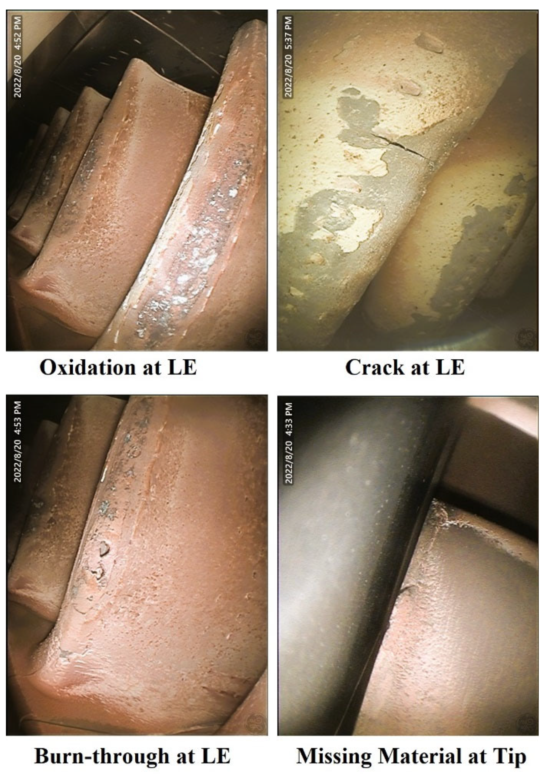
Figure 2.
Flame thermal spray system.
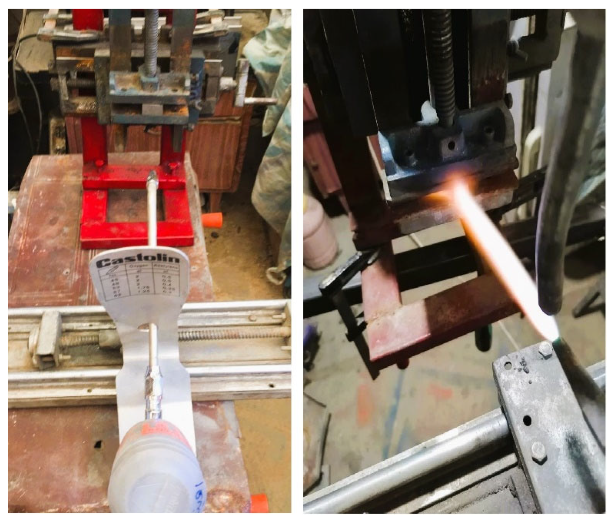
Figure 3.
Samples a) Before coating, b) after coating.
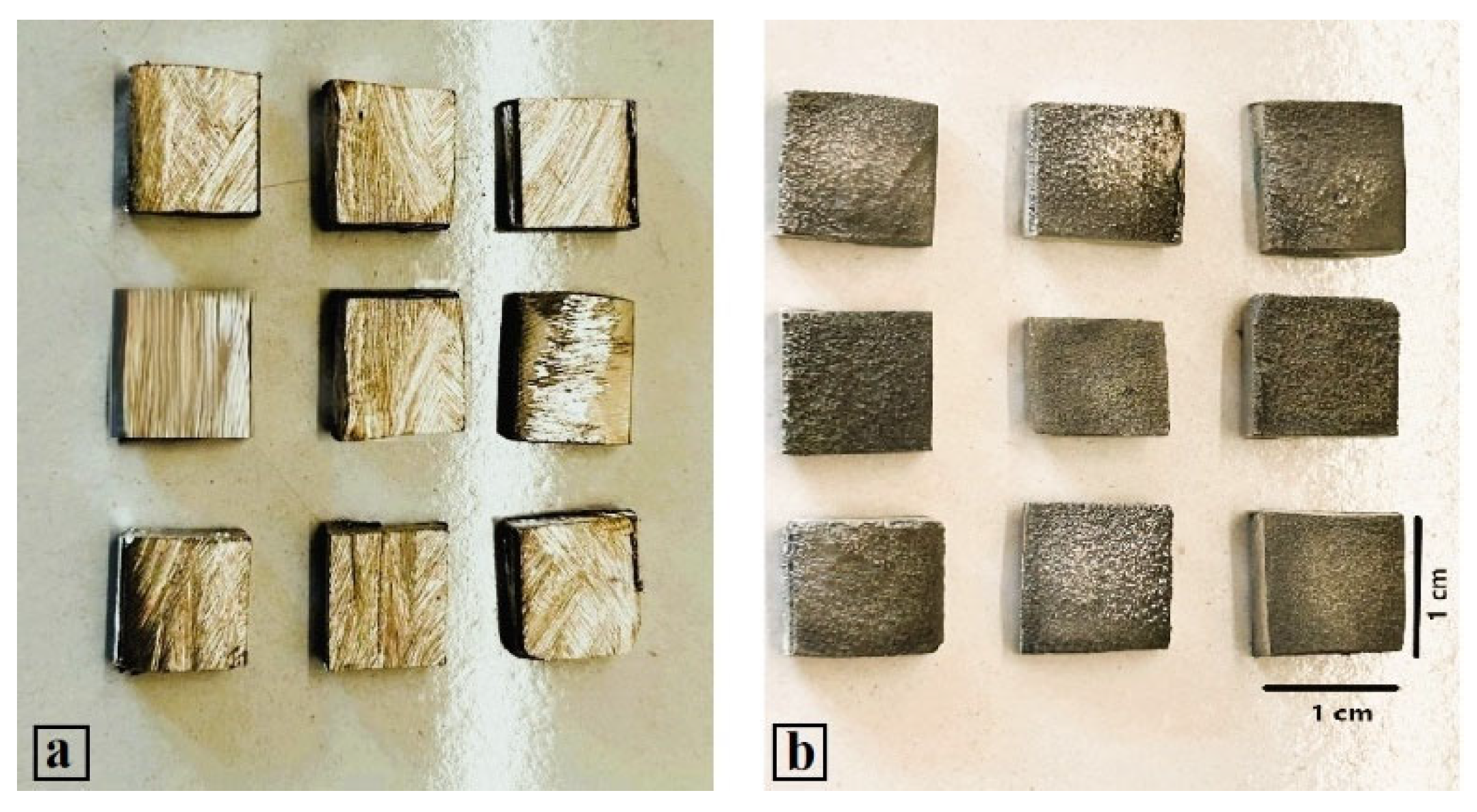
Figure 4.
Thermal cycling test, a) heating in furnace at 1100 °C, b) removing the sample after 25 min of heating, c) cooling in water.
Figure 4.
Thermal cycling test, a) heating in furnace at 1100 °C, b) removing the sample after 25 min of heating, c) cooling in water.
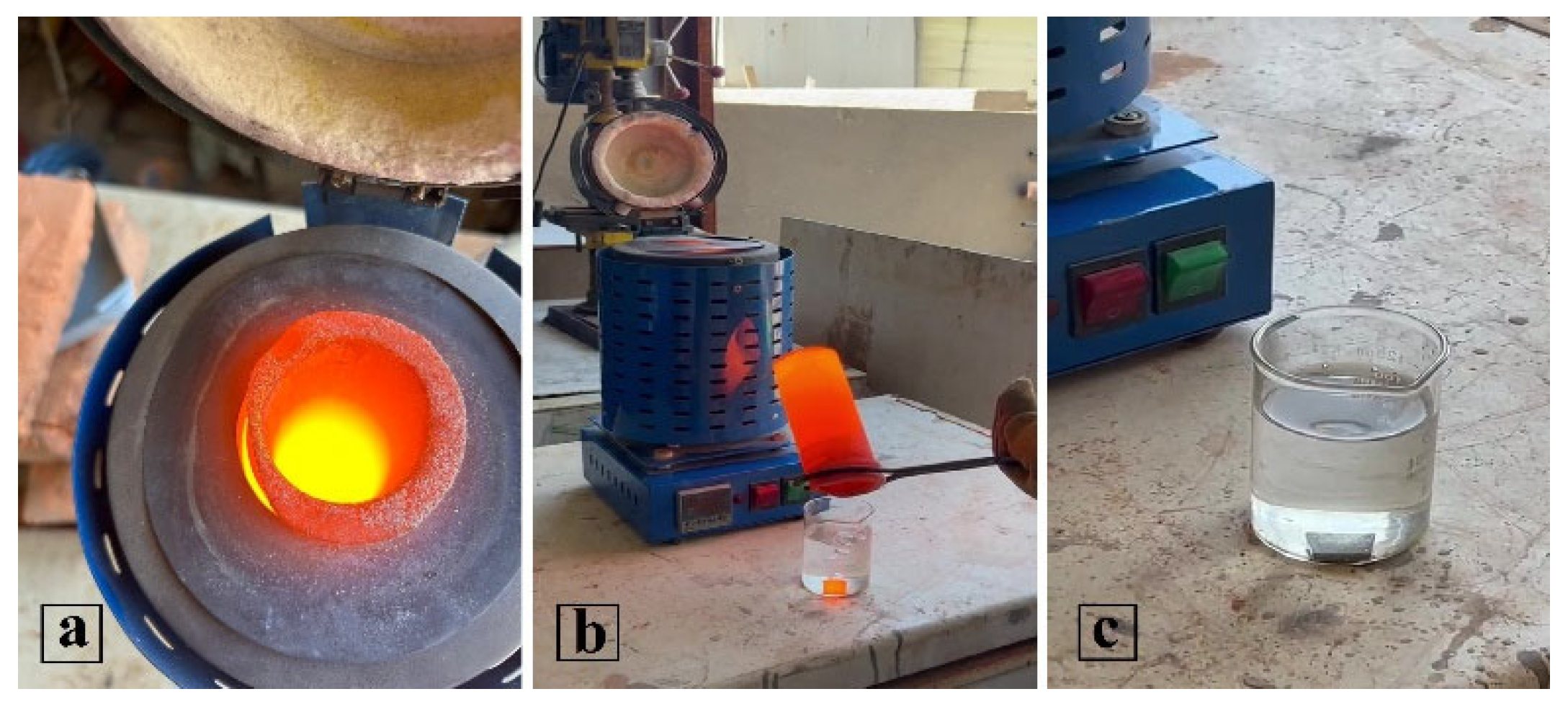
Figure 5.
a) Air jet hot solid particle erosion test, b). Silica erodent powder used for SPE test.
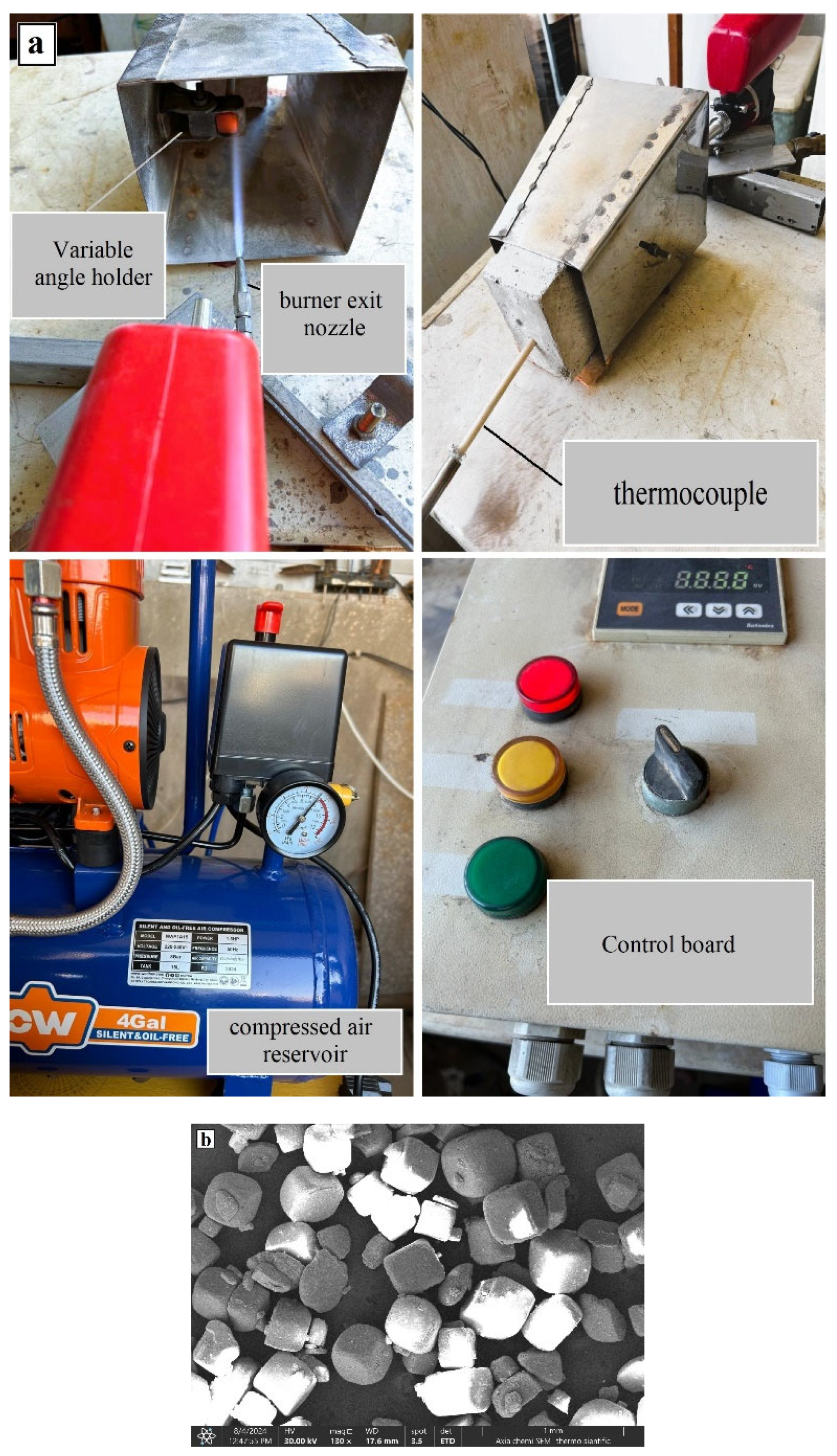
Figure 6.
Diffusion depth Main effect plot for means.

Figure 7.
a) Optimize Samples b) Diffusion depth of TBCs using optical microscopy.
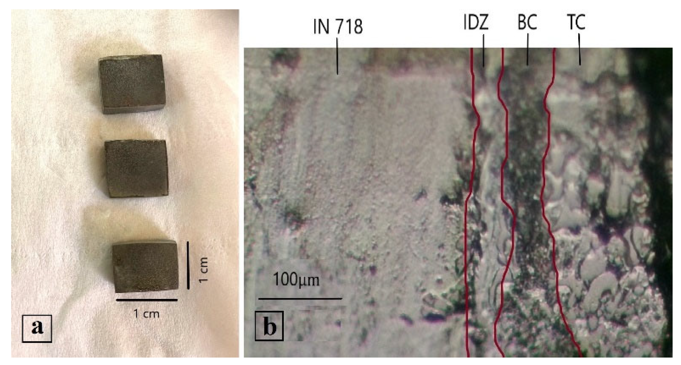
Figure 8.
Morphology of the TBC a) SEM of cross-section, b) SEM of the surface of the TBC c) EDS analysis of TBC.
Figure 8.
Morphology of the TBC a) SEM of cross-section, b) SEM of the surface of the TBC c) EDS analysis of TBC.
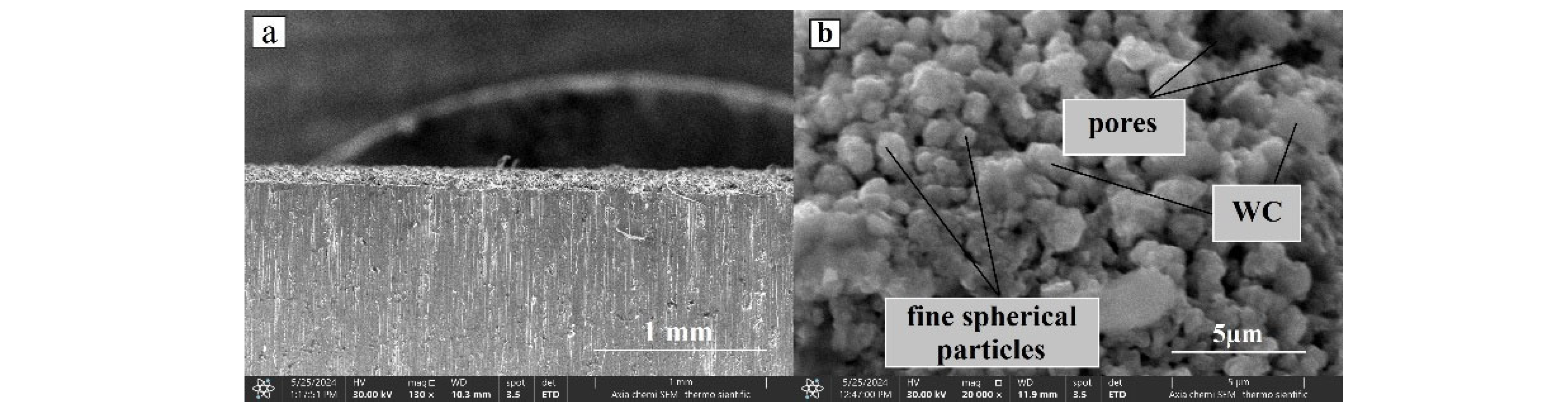
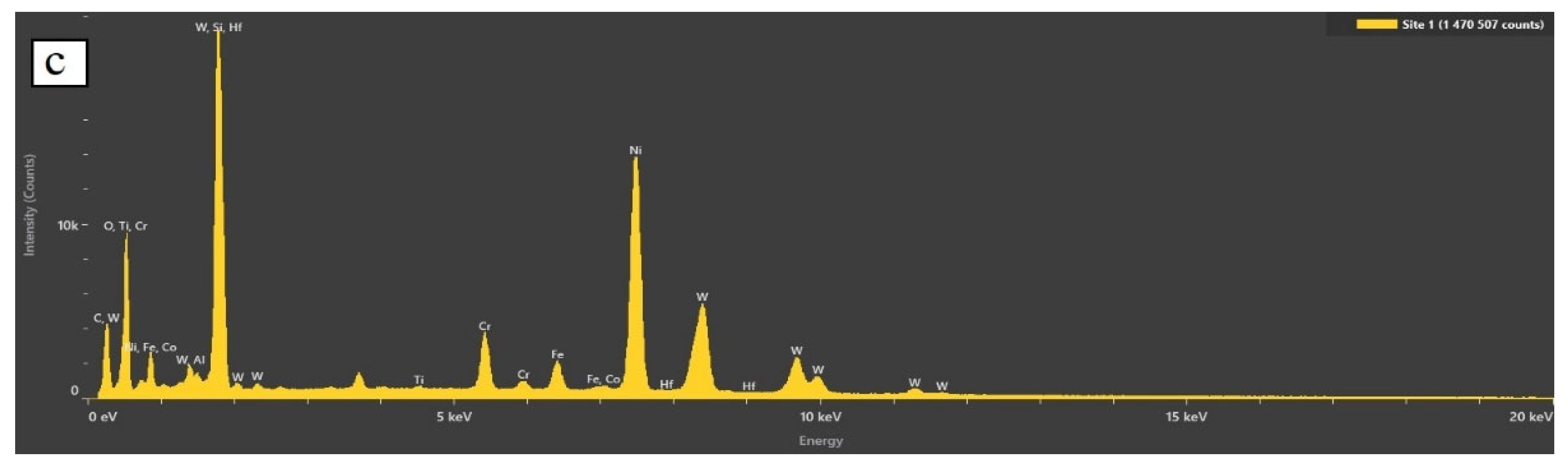
Figure 9.
X-ray diffraction spectrum of: a) the substrate and coating materials before FTHS, b) TBCs layer.
Figure 9.
X-ray diffraction spectrum of: a) the substrate and coating materials before FTHS, b) TBCs layer.
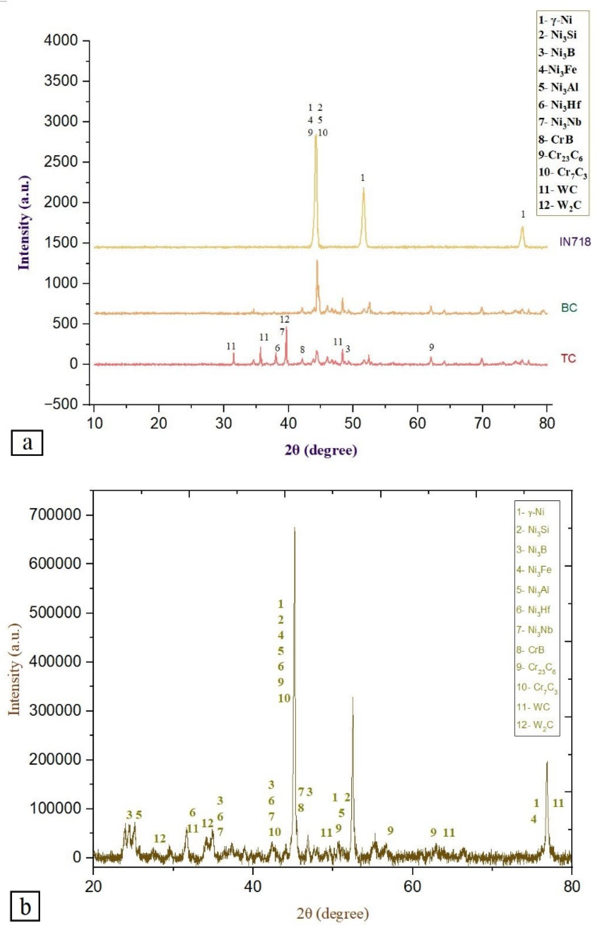
Figure 10.
Micro-hardness test results of the uncoated and coated sample.
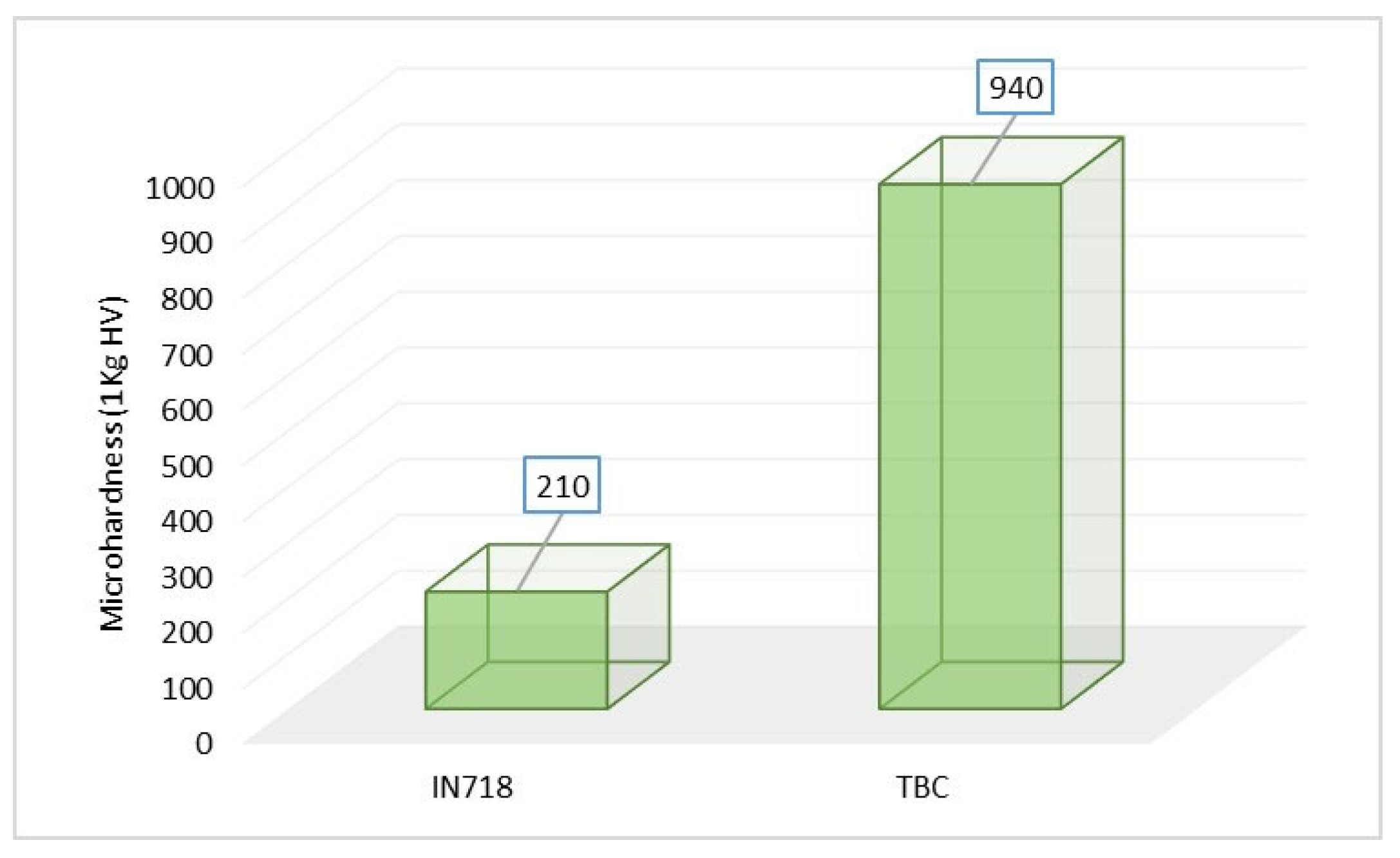
Figure 11.
Thermal cycling test results of the TBC a) Thermal cycling lifetime, b-d) Weight change as a function of cycles number for TBC with different thickness, e) samples after 600 thermal cycle.
Figure 11.
Thermal cycling test results of the TBC a) Thermal cycling lifetime, b-d) Weight change as a function of cycles number for TBC with different thickness, e) samples after 600 thermal cycle.
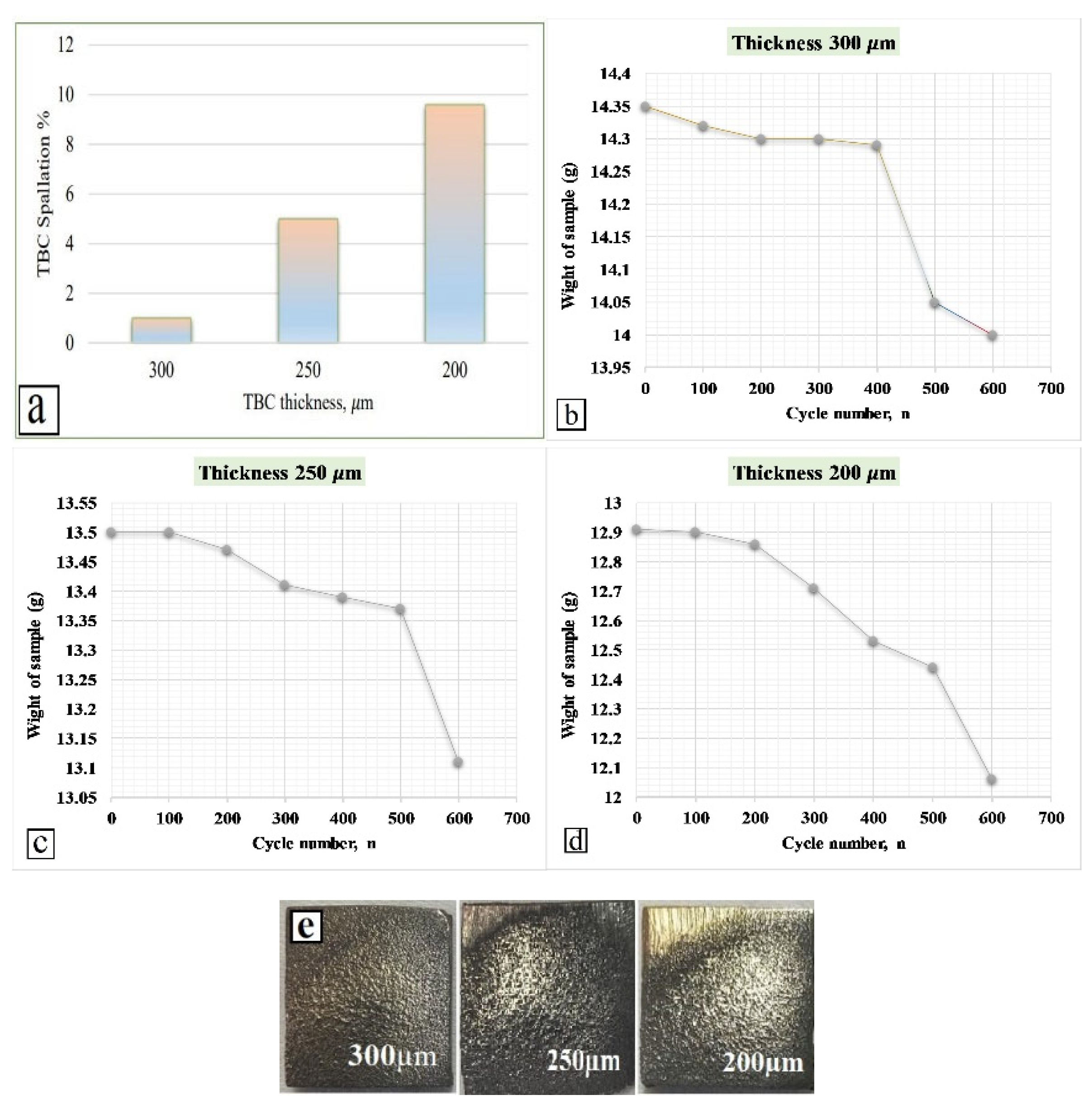
Figure 12.
a) SEM and schematic representation behavior of TBC after thermal cycling. (b-d) Cross-sectional morphologies of the three different thickness of TBCs after 600 thermal cycles b) 300µm, c) 250µm, d) 200 µm.
Figure 12.
a) SEM and schematic representation behavior of TBC after thermal cycling. (b-d) Cross-sectional morphologies of the three different thickness of TBCs after 600 thermal cycles b) 300µm, c) 250µm, d) 200 µm.
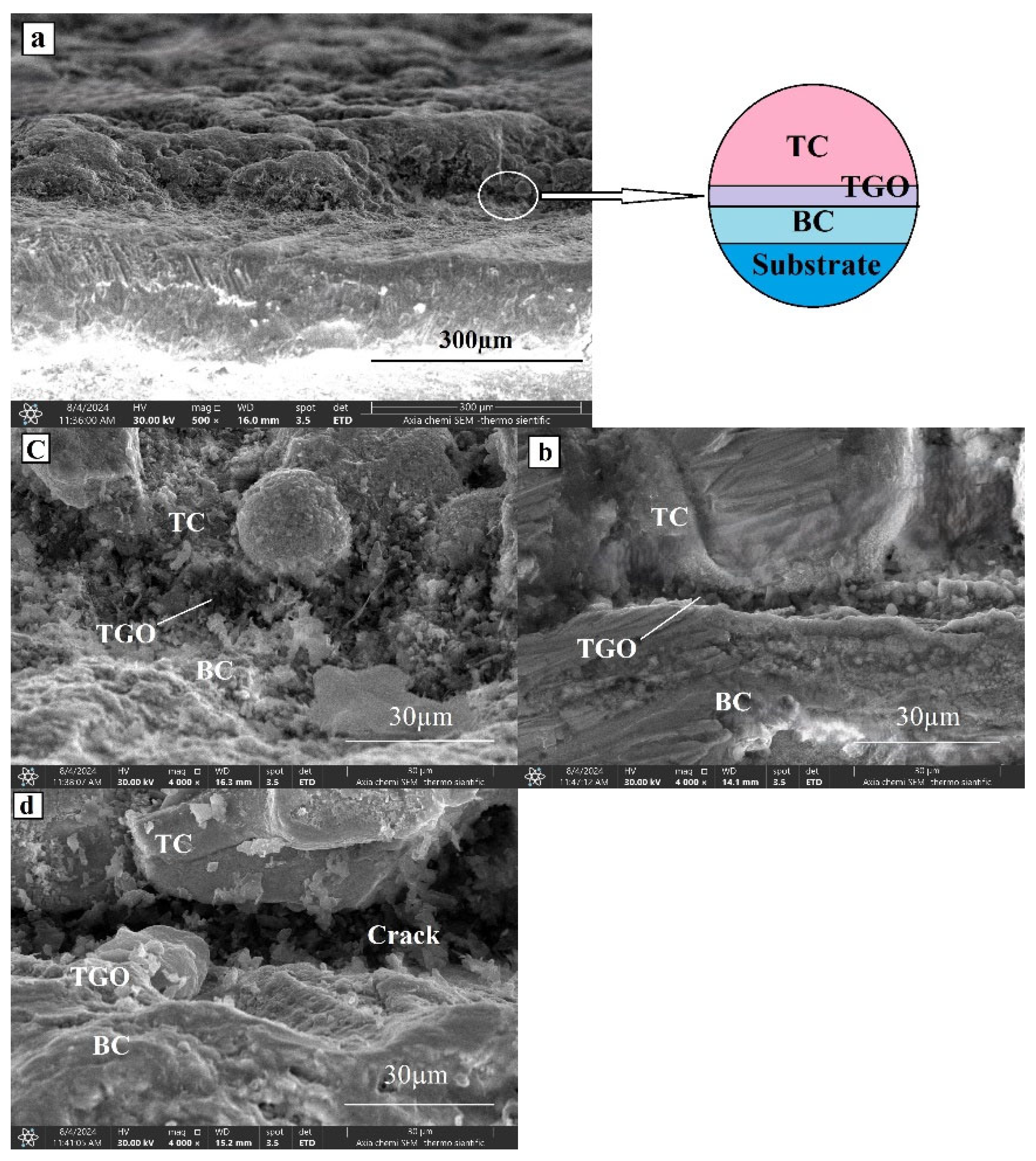
Figure 13.
Erosion rate of the TBCs at the different impact angles.
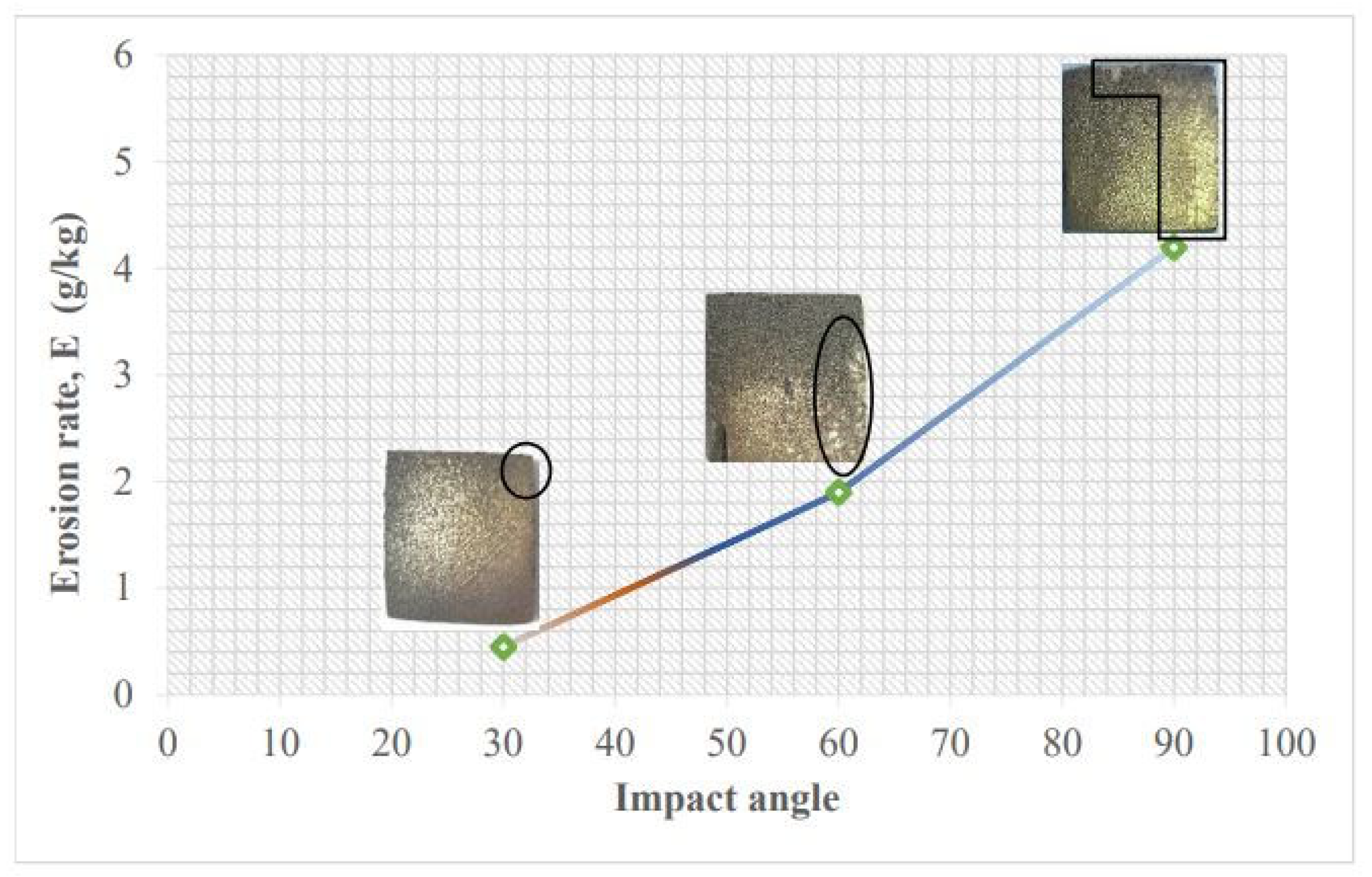
Figure 14.
Cross section SEM results of eroded TBC a) 30°, b) 60°, and c) 90° impact angle.
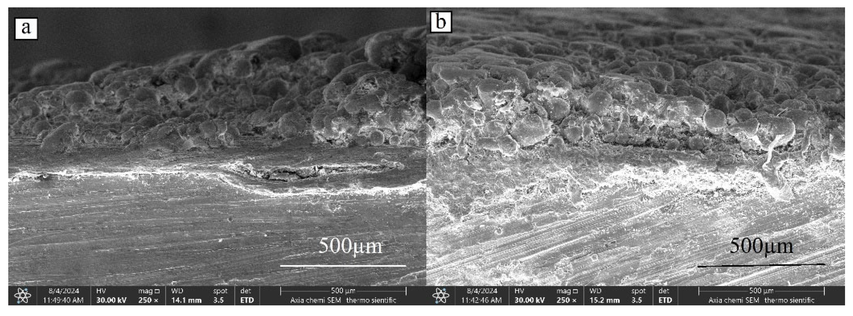
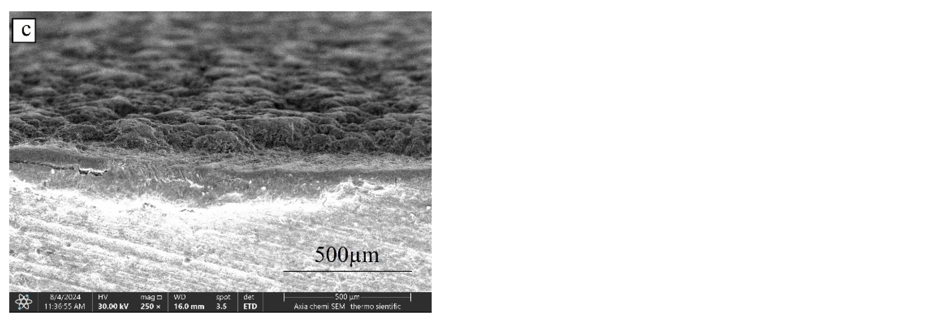
Figure 15.
a) EDS results of eroded surface of TBC at 90° impact angle, and (b-d) SEM result of eroded surface of TBC at 30°, 60° and 90° impact angle, respectively.
Figure 15.
a) EDS results of eroded surface of TBC at 90° impact angle, and (b-d) SEM result of eroded surface of TBC at 30°, 60° and 90° impact angle, respectively.
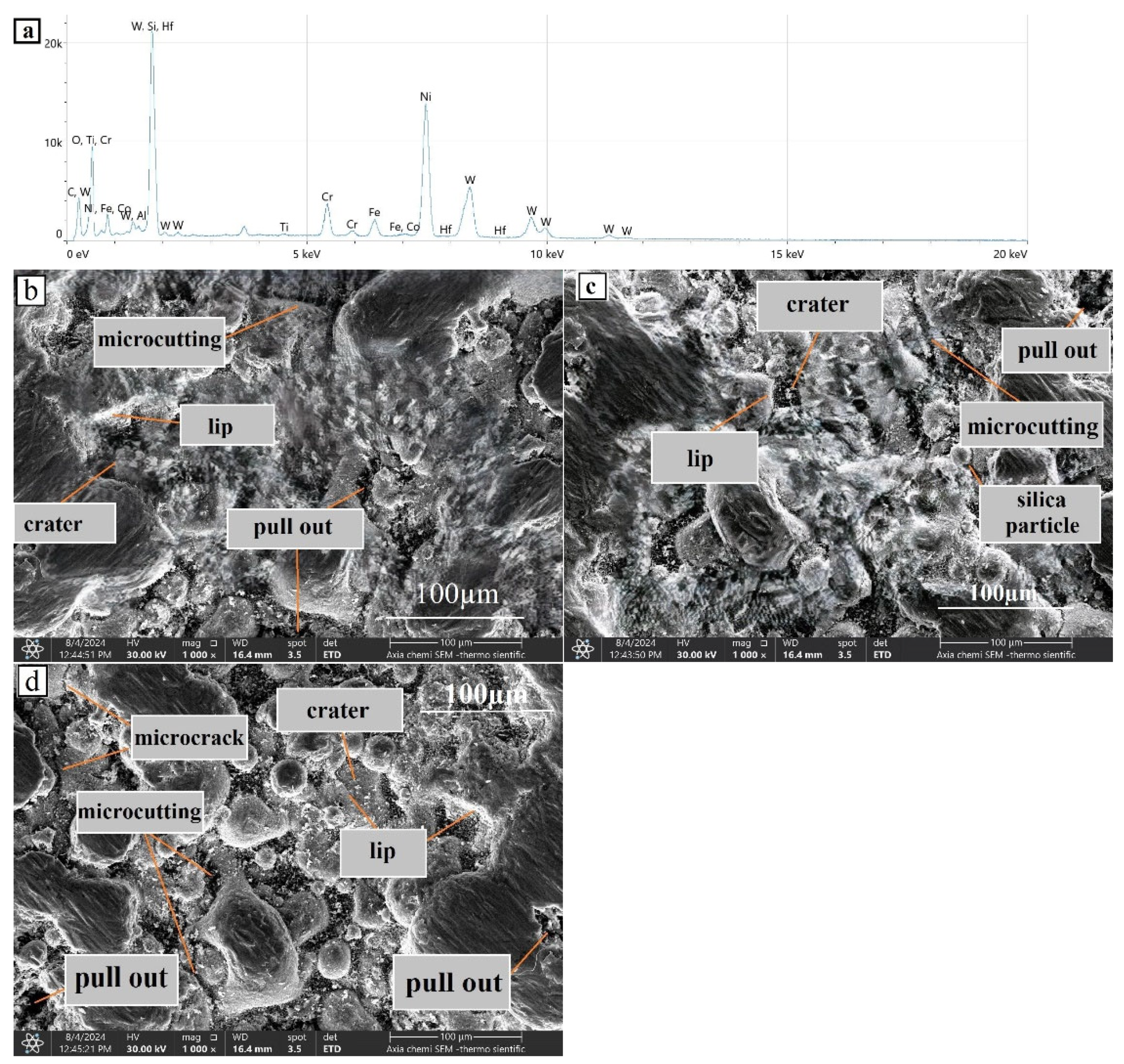

Table 1.
Chemical composition in (wt. %) of substrate and coating materials.
| Materials | Ni | Cr | Al | Fe | C | Hf | B | Si | W |
| In718 | Base | 10.5 | 0.3 | 0.5 | 16.7 | 0.4 | 1.3 | 0.6 | - |
| NiCrBSi | Base | 14.94 | 0.21 | 3.95 | - | - | - | 5.33 | - |
| Ni based-WC | Base | 3.9 | 0.3 | 2.2 | 11.8 | 0.1 | - | 3.5 | 31.5 |
Table 2.
FTHS process parameters and their levels.
| Parameter | Code | Level1 | Level2 | Level3 |
| Stand-off distance (mm) | A | 100 | 125 | 150 |
| Traverse Velocity (mm/min) | B | 100 | 200 | 300 |
| Powder Feeding (g/min) | C | 10 | 20 | 30 |
Table 3.
Taguchi Orthogonal Array (OA) Results.
| Code | A | B | C | Trail1 | Trai2 | Trail3 | Mean | S/N |
| 1 | 100 | 100 | 10 | 51 | 53 | 48 | 50.6667 | 34.09 |
| 2 | 100 | 200 | 20 | 66 | 64 | 61 | 63.6667 | 36.08 |
| 3 | 100 | 300 | 30 | 67 | 69 | 67 | 67.6667 | 36.61 |
| 4 | 125 | 100 | 20 | 47 | 48 | 44 | 46.3333 | 33.32 |
| 5 | 125 | 200 | 30 | 55 | 53 | 54 | 54.0000 | 34.65 |
| 6 | 125 | 300 | 10 | 64 | 58 | 60 | 60.6667 | 35.66 |
| 7 | 150 | 100 | 30 | 72 | 71 | 72 | 71.6667 | 37.11 |
| 8 | 150 | 200 | 10 | 66 | 68 | 65 | 66.3333 | 36.43 |
| 9 | 150 | 300 | 20 | 59 | 56 | 61 | 58.6667 | 35.37 |
Table 4.
Response results of coating diffusion for the investigated parameters.
| Level | A | B | C |
| 1 | 35.59 | 34.84 | 35.40 |
| 2 | 34.54 | 35.72 | 34.92 |
| 3 | 36.30 | 35.88 | 36.12 |
| Delta | 1.76 | 1.04 | 1.20 |
| Rank | 1 | 3 | 2 |
Table 5.
Analysis of Variance for SN ratio.
| Source | DF | Seq SS | Adj SS | Adj MS | F | Contribution,% |
| Standoff distance mm | 2 | 4.712 | 4.712 | 2.3561 | 1.26 | 37.64 |
| T. velocity mm/min | 2 | 1.879 | 1.879 | 0.9396 | 0.50 | 15.01 |
| Powder feeding g/min | 2 | 2.189 | 2.189 | 1.0943 | 0.59 | 17.4 |
| Residual Error | 2 | 3.737 | 3.737 | 1.8686 | 29.85 | |
| Total | 8 | 12.517 | 100 |
Table 6.
Confirmation Experiments under Optimal Conditions.
| Exp. No. | A | B | C | Predicted diffusion depth | Exp. Diffusion depth |
| 1 | 3 | 3 | 3 | 72.4074 | 71.43 |
| 2 | 3 | 3 | 3 | 72.4074 | 72.01 |
| 3 | 3 | 3 | 3 | 72.4074 | 72.39 |
Disclaimer/Publisher’s Note: The statements, opinions and data contained in all publications are solely those of the individual author(s) and contributor(s) and not of MDPI and/or the editor(s). MDPI and/or the editor(s) disclaim responsibility for any injury to people or property resulting from any ideas, methods, instructions or products referred to in the content. |
© 2025 by the authors. Licensee MDPI, Basel, Switzerland. This article is an open access article distributed under the terms and conditions of the Creative Commons Attribution (CC BY) license (https://creativecommons.org/licenses/by/4.0/).
Copyright: This open access article is published under a Creative Commons CC BY 4.0 license, which permit the free download, distribution, and reuse, provided that the author and preprint are cited in any reuse.


