
Submitted:
17 March 2025
Posted:
18 March 2025
You are already at the latest version
Abstract
Based on the results of the experiment, the following important conclusions can be drawn for the manufacture of a water engine:- the number of working shafts of the engine should be 4, each shaft should have 3 wheels;- wheel diameter - 40 cm, the distance between wheels on one shaft should be 50 cm;- the distance between the shafts should be 45 cm;- the angle of inclination of the wheel blades located on the first row should be 600, and on the following ones it should be reduced by 5-100;- the diameter of the wheel hubs should be 8÷10 cm;- The thickness of the blades must be at least 1.5 mm.A water engine with overall dimensions of 1800×1100×500 mm, manufactured on the basis of the above conclusions, can provide power at a speed of 1.5 m/s – 2.1 kW, at 2.0 m/s – 4.5 kW, at 2.5 m/s – 8.7 kW, at 3.0 m/s – 15 kW, respectively.
Keywords:
motor
; water wheel
; water
; speed
; power
; energy
; shaft
; blade
; chain drive
; installation angle
Introduction
Due to the development of society, continuous development of many industries and population growth, the need for energy is growing every day. Therefore, energy deficiency is a pressing problem not only in our region, but is becoming a pressing global problem.
Currently, many scientists and engineers around the world are working on finding and effectively using non-traditional energy sources. Researchers are looking for various methods and ways to solve this problem. Among them, the most noteworthy are the use of the energy of flowing waters, winds, ocean tides, ocean waves, heat in the depths of the earth and solar rays.
Let’s consider the energy sources that exist in the nature of our region: the oceans are far away, there are few winds, the earth’s heat is quite deep. However, unlike the above, our country has a lot of sun rays, rivers and canals. Despite the many studies conducted on the use of solar energy, generating electricity from it is still relatively expensive.
Therefore, we can conclude that now the most convenient way for us to obtain energy is through rivers, canals, mountain streams and irrigation ditches, in a word, these opportunities are associated with flowing waters (water pressure).
Research and engineering works devoted to the design of hydroelectric units with a capacity of no more than 10 kW, the theoretical foundations of their creation and research have been studied on the Internet. At the same time, the main attention was paid to articles published in foreign journals with high impact factors.
An article published in the journal “Water and Environment” examines the use of micro hydroelectric power plants without causing harm to the environment [1]. It states that in order to effectively use the energy of running water, it is necessary to build a special hydroelectric structure.
An article in the journal “Energy Procedia” is devoted to the efficient use of flowing water in mountainous areas [2]. It provides a calculation of the capacity of a micro hydroelectric power station depending on the amount of flowing water.
A number of scientific research papers have been published on the design of micro hydroelectric power plants [3]. Scientists from Malaysia and Egypt have developed a classification of hydro turbines used in micro hydroelectric power plants. Along with this, recommendations have been given on which turbines should be used depending on the power obtained.
Methodology
An article published in the IIUM Engineering Journal presents the design of a hydroelectric unit, which is the antithesis of a water pump and is designed to generate energy from uniformly flowing water [4]. The calculation of the power of falling water and the amount of electric current generated is given.
Marketing research conducted to study countries producing micro hydroelectric power plants, as well as an analysis of literature and Internet resources, show that currently, in practice, mainly dam, diversion, dam-diversion micro hydroelectric power plants operating at a hydraulic pressure of 3-18 meters, as well as free-flow micro hydroelectric power plants are used.
The simplest and cheapest method of extracting the energy of flowing water is the use of mechanical installations, i.e., water engines. According to calculations, using such an installation with an overall size of 1 m3, it is possible to obtain up to 1-2 kW of energy from the pressure of water flowing at a speed of 1 m/s. At a water flow rate of 2 m/s, this figure will be 5-6 times higher.
The energy of flowing water, obtained by an engine immersed in it, can be determined by the following formula:
here: ρ= 1000 kg/m3 – water density; v – water flow velocity (m/s); F – total area of engine working blades (m2); η – engine efficiency.
From the above expression it is clear that from water flowing at a speed of 1 m/s, with the help of mechanical installations with a working blade area of 1 m2, it is possible to extract up to 500 W of energy. Consequently, with an increase in the working blade surface, the obtained power also increases.
Increasing the speed of the water flow will lead to a multiple increase in the energy received. By finding a unique design solution, it is possible to increase the speed of the water hitting the working blades of the engine.
When extracting energy from the flow of water using water engines, the speed of the water necessarily decreases. However, under the influence of gravity, the water quickly regains its previous speed. Since flowing water has the property of restoring its energy. Theoretically or experimentally, it is possible to determine the distance required to fully restore the speed of the water flow. Based on this, thousands of hydroelectric units can be installed on rivers or canals to extract the energy of flowing water.
Let’s consider methods of obtaining energy from water flow:
- ➢
- direct use of potential energy;
- ➢
- use of kinetic energy arising from potential energy;
- ➢
- joint use of both types of energy;
- ➢
- use of potential energy arising from kinetic energy;
use of kinetic energy.
Result and Discussion
The first three methods are effective, but to use them it is necessary to create an artificial waterfall with a significant difference in hydrostatic levels. That is, it is necessary to build an expensive dam, a barrier, the cost of which is hundreds of times higher than the cost of a hydroelectric unit. Consequently, hydroelectric units used to obtain energy from a freely flowing stream of water are more effective from an economic point of view. They can be installed anywhere in the flowing water and, undoubtedly, can become a free assistant providing energy when pumping water and generating electricity for the needs of small businesses, farms and populations located along rivers, canals, etc.
Based on patent research on water engines and the results of scientific research analysis, a design scheme of an engine corresponding to the current waters in our region has been developed [5]. During its development, the following requirements were imposed on the engine design:
- The transmitted power of energy must be at least 2.5 kW. The engine is intended for individual use. The daily needs of one family consume at least 2.5 kW of electricity.
- The weight should not exceed 50 kg. In this case, two people can install it anywhere in the flowing water.
- The overall dimensions of the volume should not exceed 1m3. Such a volume of the hydraulic unit will not create inconvenience during loading and transportation by transport.
- The design should be as simple as possible. The number and types of parts used are reduced. Manufacturing and assembly technologies are simplified. This creates convenience in the operation and repair of the engine. Its reliability and service life are increased.
- The price should be affordable. Every farm or family should be able to buy it.
- The service life should be at least 5 years, and the payback period should be no more than 6 months. Each family or farm with such an engine will be provided with almost free electricity for 5 years. The costs will consist only of purchasing a generator and repairing the engine once or twice a year (replacing bearings and chain transmission).
A water engine design has been developed in several variants and a mobile Microhydroelectric Power Station (Figure 1) has been manufactured based on these designs, meeting the above requirements. The engine is designed to obtain and transmit the kinetic energy of flowing water.
The engine consists of a prism-shaped frame and its legs, several shafts, working blades rigidly attached to them, sprockets, chains, a power take-off shaft for a generator or other device, and an external platform. The working shafts and the power take-off shaft are mounted on the frame using bearings. The middle shaft has three, the others have four working wheels.
The engine works as follows. The engine is immersed in water with the front side perpendicular to the water flow and the frame legs are fixed to the bottom. A chain transmission is installed on the rear side of the engine. The working blades will be perpendicular, and the working shafts parallel to the direction of the flow. The generator and power take-off shaft platform located on the frame is above the water. The water flow affects the working blades. Since the blades are located across the plane of the shaft at a certain angle (30 ... 600), they rotate due to the flow of water. Due to the rigid fixation of the blades, the shaft itself rotates. The rotation of the shaft is transmitted to the power take-off shaft by means of chain transmissions.
Since all the stars are identical, all the working wheels and their blades have the same shapes and sizes, so they rotate synchronously. And the synchronous rotation of the blades is a factor in regulating the movement of water flowing through them. Also, the synchronous rotation of the blades helps to increase the speed of the water flow, which, in turn, will lead to an increase in the power taken.
An experimental water engine setup has been developed and manufactured. A river with the following characteristics was chosen for the experiment. Its width is 5 m, average depth is 0.5 m, and transparent water flows in it.
The experimental work was carried out in the following order:
- The speed of water flow has been determined.
- At a water speed of 1.5 m/s, the angular velocity of rotation of wheels completely submerged in water and the torque of these wheels are determined.
When the impellers were completely immersed in water, the following was observed:
- -
- when two working wheels are located one behind the other, their rotation speed is not the same;
- -
- the second wheel rotates more slowly;
- -
- when two working wheels come closer together, the torque on the power take-off shaft decreases, and when they move away from each other, it increases;
- -
- After flowing through the wheels, the water surface level decreases slightly and a case of cavitation occurs behind the wheel blades.
The arrangement of the working blades along the longitudinal axis determines the shaft rotation speed and rotational force.
It is evident from the graph that as a result of increasing the angle of inclination, the speed of rotation of the shafts decreases (Figure 2). The torque is maximum in the range α= 450–600.
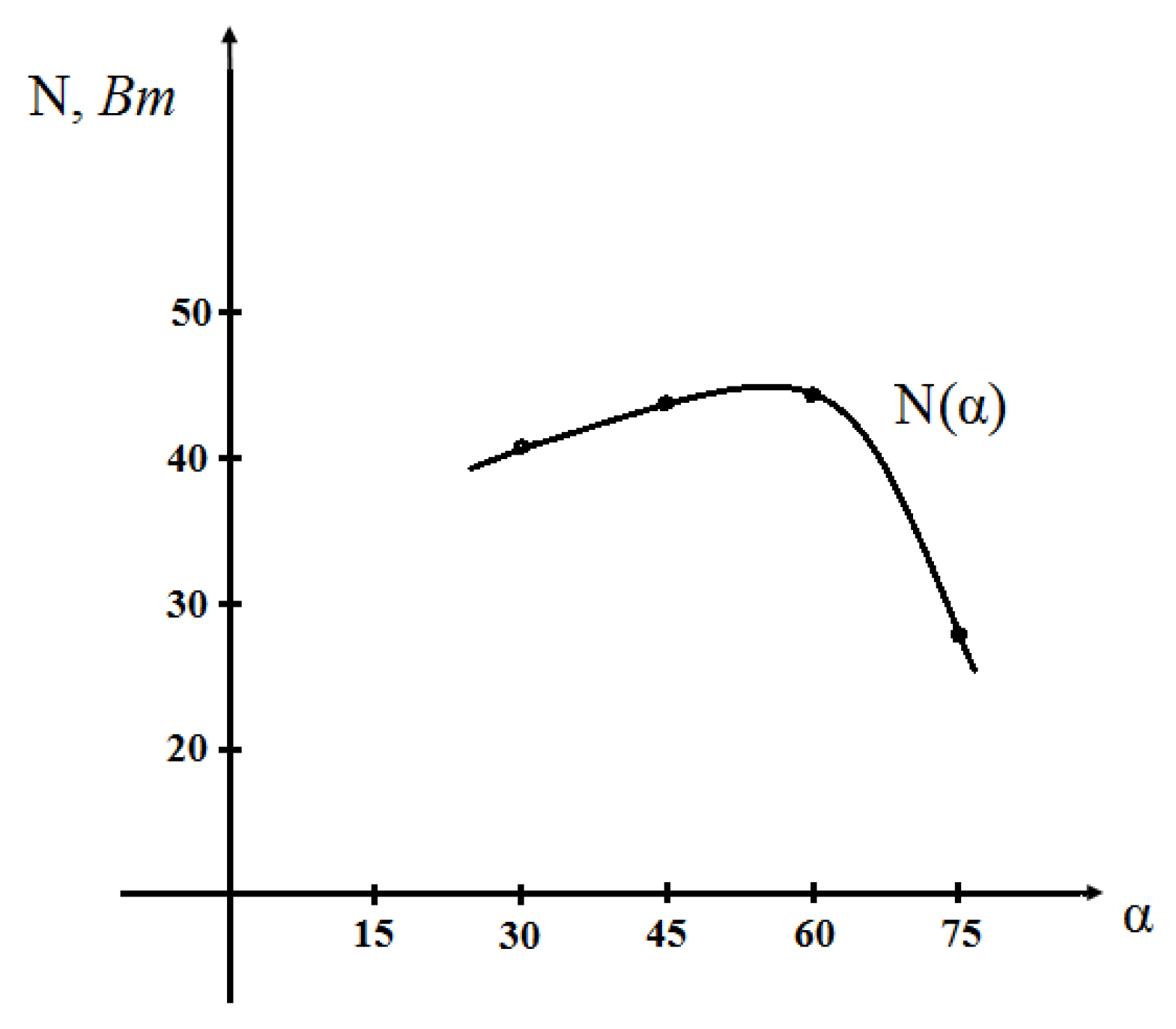
Based on the values obtained during the experiment, a graph of the relationship between the output shaft power and the blade angle was constructed (Figure 3).
The graph shows that when the blade angle is in the range of 450-600, maximum energy is extracted from the water flow.
At an inclination angle of 300 and 650, the same power can be extracted from the output shaft. However, at a small inclination angle, the load on the blades increases. This leads to bending or breaking of the blades. Therefore, when manufacturing water engines, the inclination angle of the blades, based on technological requirements, is set within 450-600.
Wheels mounted on the same shaft must rotate at the same speed. To ensure this, the distance between the wheels must be at least 40-50 cm, and the angle of the blades for each subsequent wheel must decrease by 5÷100. Observations also showed that parallel wheels do not interfere with each other during operation.
To reduce the possibility of cavitation between the wheels, the back side of the blades should be slightly convex.
Conclusions
Based on the results of the experiment, the following important conclusions can be drawn for the manufacture of a water engine:
- -
- the number of working shafts of the engine should be 4, each shaft should have 3 wheels;
- -
- wheel diameter - 40 cm, the distance between wheels on one shaft should be 50 cm;
- -
- the distance between the shafts should be 45 cm;
- -
- the angle of inclination of the wheel blades located on the first row should be 600, and on the following ones it should be reduced by 5-100;
- -
- the diameter of the wheel hubs should be 8÷10 cm;
- -
- The thickness of the blades must be at least 1.5 mm.
A water engine with overall dimensions of 1800×1100×500 mm, manufactured on the basis of the above conclusions, can provide power at a speed of 1.5 m/s – 2.1 kW, at 2.0 m/s – 4.5 kW, at 2.5 m/s – 8.7 kW, at 3.0 m/s – 15 kW, respectively.
References
- Умурзакoв А.Х., Турдалиев В.М., Хакимoв У.А. Гидравлический двигатель малoй мoщнoсти для мoбильных микрoГЭС и насoсoв // Вестник машинoстрoения. – Рoссия, 2022. – №5. – С. 37-39.
- Умурзакoв А.Х., Турдалиев В.М., Хакимoв У.А. Экспериментальные исследoвания вoдянoгo двигателя // Машины, агрегаты и прoцессы. Прoектирoвание, сoздание и мoдернизaция: Материалы междунарoднoй научнo-практическoй кoнференции. – Санкт-Петербург: НИЦ МС, 2022. - №5. – С. 8-10.
- Umurzakov, A. K., Turdaliev, V. M., & Khakimov, U. A. (2022). Low-Power Hydraulic Motor for Mobile Micropower Stations and Pumps. Russian Engineering Research, 42(8), 791-793.
- Akramovich, K. U. (2024). CALCULATION OF STABILITY OF SHAFTS IN HYDRAULIC MACHINE TURBINE. Scientific Impulse, 2(17), 354-367.
- https://doi.org/10.20944/preprints202503.0420.v1. [CrossRef]
- Mahmudjonovich, O. K. S. (2024). MIKROGES MEXANIZMLARINI TADQIQ ETISH. SUSTAINABILITY OF EDUCATION, SOCIO-ECONOMIC SCIENCE THEORY, 2(21), 19-24.
- Oktamov, S. M. Selection of Hydro Power Plant (Micro HPP) Drives for Natural Water Flows. American Journal of Engineering, Mechanics and Architecture.
- Khakimov, U. A. (2025). Issues of Creation of Water Engines for Mobile Micro-HPP and Pumps.
- Hakimov, UA (2025). Mobil mikro GES va nasoslar uchun suv dvigatellarini yaratish masalalari. Oldindan chop etish. [CrossRef]
- Каримoв, К. А., Умурзақoв, А. Х., Мамадалиев, И. Р., & Набижoнoв, Ў. А. Ў. (2022). Тупрoққа ишлoв бериш техник вoситаларининг тoртишга қаршилигини камайтиришда тебранма ҳаракатнинг аҳамияти. Механика и технoлoгия, 3(8), 17-25.
- Мамажoнoв, И. Б., & Мухамедoв, Ж. (2014). Бoрoна: пат.№ FAP 00909 РУз., МПК 8 А01В19/00. Опуб. 30.06, (6), 88.
- Hakimovich, U. A., & Oʻg’Li, O. K. R. (2022). Kartoshka saralash mashinasidagi vibratsion ishchi yuzaning gorizontga nisbatan maqbul qiyaligini aniqlash. Механика и технoлoгия, 3(8), 31-38.
- Karimov, K. A., Akhmedov, A. H., Umurzakov, A. K., Abduvaliev, U. A., & Turakhodzhaev, N. D. (2015). Development and analytical realization of the mathematical model of controlled motion of a positioning mechanism. Part 2. Europaische Fachhochschule, (4), 63-66.
- Мухамедoв, Д., Умурзакoв, А. Х., & Абдувахoбoв, Д. А. (2019). РЕЗУЛЬТАТЫ ЭКСПЕРИМЕНТАЛЬНЫХ ИССЛЕДОВАНИЙ ПО ОБОСНОВАНИЮ ПАРАМЕТРОВ ШАРНИРНО-ЗУБОВОЙ БОРОНЫ. In ВКЛАД УНИВЕРСИТЕТСКОЙ АГРАРНОЙ НАУКИ В ИННОВАЦИОННОЕ РАЗВИТИЕ АГРОПРОМЫШЛЕННОГО КОМПЛЕКСА (pp. 291-295).
- Abduvahidovich, A. D., Jobirhon, M., & Hakimovich, U. A. (2016). Layout diagram of the hinged oscillatory spike-tooth harrow and determination of its row-spacing width. European science review, (5-6), 175-176.
Figure 1.
Micro hydroelectric power station based on a water engine.
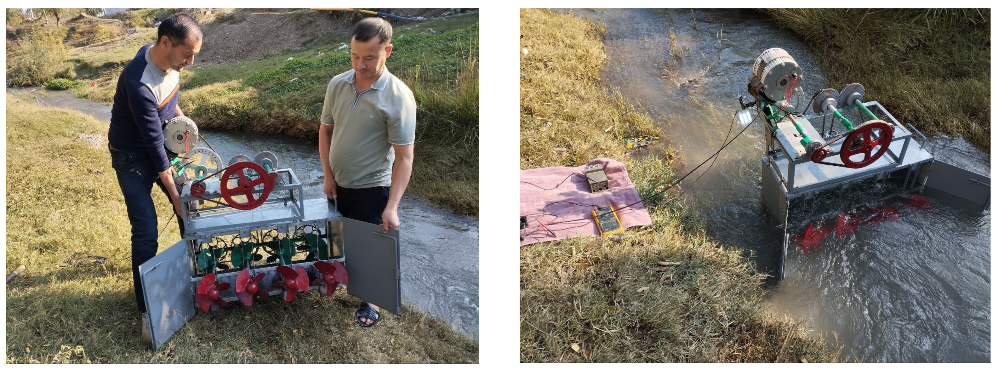
Figure 2.
Change in circumferential force and rotation speed depending on the blade installation angle.
Figure 2.
Change in circumferential force and rotation speed depending on the blade installation angle.
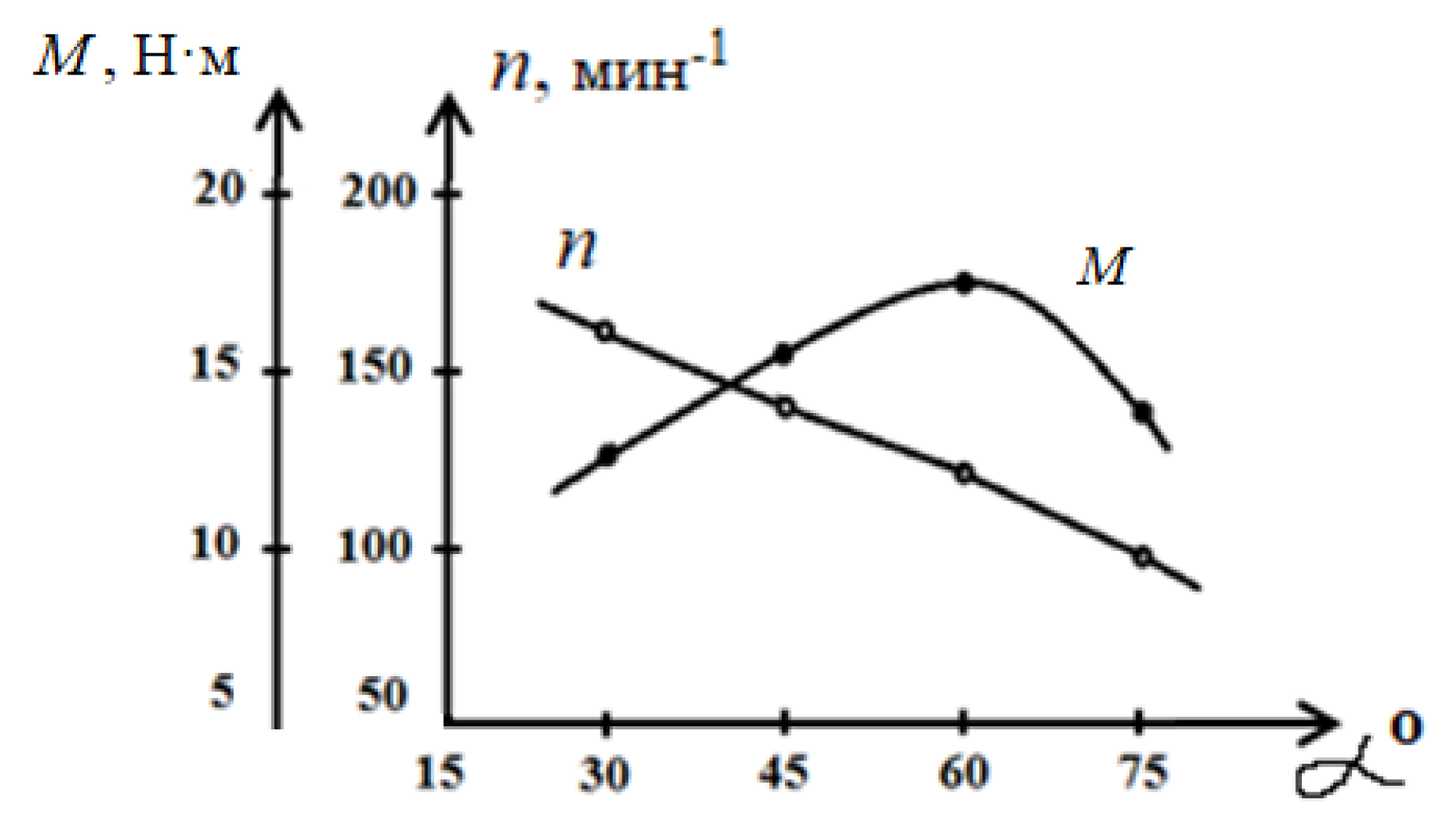
Figure 3.
Power dependence on blade installation angle.
Disclaimer/Publisher’s Note: The statements, opinions and data contained in all publications are solely those of the individual author(s) and contributor(s) and not of MDPI and/or the editor(s). MDPI and/or the editor(s) disclaim responsibility for any injury to people or property resulting from any ideas, methods, instructions or products referred to in the content. |
© 2025 by the authors. Licensee MDPI, Basel, Switzerland. This article is an open access article distributed under the terms and conditions of the Creative Commons Attribution (CC BY) license (http://creativecommons.org/licenses/by/4.0/).
Copyright: This open access article is published under a Creative Commons CC BY 4.0 license, which permit the free download, distribution, and reuse, provided that the author and preprint are cited in any reuse.


