Submitted:
12 March 2025
Posted:
13 March 2025
You are already at the latest version
Abstract
Scaling is a critical activity in tunnel construction that significantly affects both safety and maintenance costs. Recognized as a high-risk mining operation, it poses substantial dangers to operators, with a notable incidence of accidents and fatalities in the tunneling industry. Large-scale projects such as hydroelectric power plants (HPP) present significant challenges, including substantial vertical elevations and the constraint of a single heavily trafficked main road. These conditions often necessitate semi-mechanized work methods for tunnel construction, which can be labor-intensive, time-consuming, and pose significant safety risks. To address these challenges and improve efficiency, an alternative mechanized method was evaluated and implemented. This approach involved deploying a fleet of excavators equipped with hydraulic hammers and advanced protection systems. Considering local regulations, the Caterpillar M313D wheel excavator and Atlas Copco SB452SC hydraulic hammer were selected for their superior operational performance and ability to mitigate risks associated with scaling activities. The standard scalers and their subsystems were evaluated for their reliability and availability, using data from underground mining operations to guide the configuration and decision-making process. This approach aimed to address operational challenges while being constrained by investment costs, high depreciation expenses due to the shorter project duration, and demanding work conditions. The proposed solution was implemented in tunnel construction for an HPP in Chaglla project over three years. A fleet of six-wheel excavator systems demonstrated effective performance, successfully adhering to the project's safety policies and operational goals pursuing zero fatalities, and high availability and reliability.
Keywords:
Scaler
; Construction
; Excavator
; Hydraulic hammer
; Protection Systems
1. Introduction
Tunnel construction using the traditional method of blasting and loading involves scaling activity to remove the loose rock from the tunnel roof after blasting. The effectiveness of scaling increases the safety of workers and machinery and also the structural integrity of tunnels [1], Figure 1. Regulations changed due to concerns about fatalities, incident ratios, and accident records in the tunneling industry. Also, the traditional methods, which primarily involved manual or semi-mechanized scaling, were limited in some cases due to the tunnel height [2], and were also under pressure to be mechanized.
Scalers are considered a critical type of machine, which play an important role in improving the safety in underground operations; however, they have the highest repair cost rate, and lower reliability (indicators MTBF: Mean time between failures; MTTR: Mean time to repair in hours), and lower availability in comparison to other kinds of underground machinery. Figure 1 [3].
In Peru, official statistics from 2009 to 2023 given by the Energy and Mining Ministry (Ministerio de Energía y Minas, MINEM) and the Supervisory Body of Private Investment in Energy and Mines (Organismo Supervisor de la Inversión en Energía y Minería, OSINERGMIN) reported more than 85 fatalities due to rockfall incidents, and safety protocols were strengthened and mechanization boosted [5].
Supreme Decree No. 024-2016EM established the obligation of mechanizing scaling if the height is over 5.0 m. Furthermore, it assigned the acceptance responsibility for the type of equipment to the company, which was in charge of establishing the criteria for the mechanized activity [6].
The extended use of scalers is also limited by the project execution duration, the depreciation time, the high investment cost, the machinery size, the tunnel size, the delivery time, and the technology available. Other technical factors are the methodology of operation, especially for construction projects with shorter execution times, the acquisition investment, and the need for accelerated depreciation [7]. These limitations actively motivate the exploration of alternative machinery that is more cost-effective without compromising safety or efficiency [8].
The Supreme Decree No. 024-2016 EM was developed to set standards for the mechanization of scaling activities and for operations in Peru [9]. The goal was to reduce the risks associated with manual and semi-mechanized scaling to protect workers’ health and promote a safer environment [10]. Historically, mining companies implemented alternative machinery, such as hydraulic excavators, skid steers, and hydraulic hammers [3].
However, reports evaluated showed the need to improve the availability and reliability of traditional use of scalers and a gap in knowledge of optimized application of hydraulic wheel excavators and hydraulic hammers including complementary protection systems to safeguard the machine and the operator’s integrity [8]. In addition, there is a need to know the performance in an extended time of operation during three years and the efficacy to be used as utilitarian and multi-purpose tools [11].
The current research was focused on the performance evaluation of six hydraulic excavators and hydraulic hammers as scalers in the construction of a hydroelectric power plant, including the statistical analysis of accident recurrence in the mining and construction industries and the evaluation of their efficacy, the decision process, the rationale, and operational performance [12]. Finally, it presents the configuration and installation of protective systems for the hammer excavator as a set group and assesses their impact on safety. The research delivers insights and recommendations for future improvements, contributing to knowledge on tunnel construction safety and mechanization [13].
2. Scaling Challenges and Mechanization Need
Scaling is considered a high-risk activity in tunnel construction of HPP projects, due to the highest traffic and multiple activities during worker displacement and operation, especially when the scaling activity is done manually and semi-mechanized [14]. The construction method chosen affects safety and the level of incidents and accidents, prompting a critical evaluation of traditional or conventional methods [9].
The strength of regulations to mechanize scaling activities improves worker safety (Figure 2) and is a fundamental activity in the drilling and blasting cycle construction method for tunneling. Also, according to safety standards, new techniques to mechanize this activity reduce the risks [15]. Also, dynamic solutions in the mining and construction industries incorporate and test alternative machinery, such as hydraulic excavators equipped with hydraulic hammers, to reduce the risk of loose rock after blasting operations [16].
The increase in technology in the scaling activity represents a higher initial investment, justified by the reduction in accidents and the company’s safety event records, as well as the potential for multi-roll equipment in construction projects [17]. Also, projects and companies are valued with high scores if they comply with safety and health regulations. This kind of action conveys an industry-wide commitment, boosting the development of new methods and technologies for safer and more efficient practices [9]. This transition illustrates a significant paradigm shift in the construction and mining industries, prioritizing worker safety and operational efficiency amidst evolving technological and regulatory landscapes [18].
2.1. Statistical Analysis for Safety Trends
OSINERGMIN reported a decrease in the number of fatalities during the scaling (as a result of falling rocks) from 2002 to 2023 (Figure 3) [19]. The tightening of the safety regulations progressively improved the safety conditions in mining and tunneling construction activities. An estimation of the economic impact for companies for each case of fatal accident [20] and, additionally, the negative register in the dossiers for companies with reported accidents. Afterward, companies labeled as high-risk had operations stopped until the implementation of a crisis management plan and the resolution of legal claims and prosecutions [9].
The statistical Poison model (equation 1), was used considering the reports from Peruvian government offices like OSINERGMIN to confirm the probability of recurrence of repetition of fatal events in the activity despite the incorporation of regulations and the trend in the importation of scalers for the activity [21]. The decision of a specific system was taken considering potential vulnerabilities for the machinery, and operators during the scaling [22].
Where:
, x = Event
The probability and risk of the recurrence of fatal events due to the falling of rocks was estimated, considering that the event could happen during the work or after it [21]. As a consequence, it was inferred that these are directly related; therefore, they converged to the same result. The Poisson distribution was applied to estimate the accumulated probability over a determined number of fatalities and incidents that could happen the following year [23].
It was interpreted that the probability of fatality could occur during the scaling activity, and higher than one fatality per year was 100% (Figure 4); higher than 5 fatalities per year 99.98% and the value remains over 20 fatalities with a 34.32% of probability. Since it is not certain where the event could take place, it was assumed preventively that cases could occur in any project or development unit during the scaling in tunnel construction [24].
3. Proposed Work
The conceptualization of the alternative scaling method, the design, implementation, and operation were conducted during the construction of the Chaglla HPP project, located in the Chaglla and Chinchao districts of Pachitea province in the Huanuco region of Peru [25]. Its design included the construction of 14.7 km of hydraulic tunnels for power generation.
The traditional methods of blasting and earthmoving were chosen based on the varied geological and environmental conditions [26]. Consequently, as part of their activities, the use of wheel excavators equipped with hydraulic hammers for scaling were implemented to target this critical step in ensuring the rock structural integrity and safety for workers and machinery. This adaptation, including the process analysis and the use of complementary protection systems, sets a precedent for future endeavors in similar engineering and environmental settings, especially for projects with an execution time of three years or less [12].
3.1. Design Approach
The likelihood of accidents was statistically analyzed based on tunnel scaling mechanization to improve safety according to local standards [20]. The approach adopted for the deployment of hydraulic excavators for scaling the HPP Project faced a tight deadline of three years for tunnel construction. The project required machinery within budget constraints but also capable of operating effectively within the specific confines of tunnel dimensions [27].
The design criteria included the technological adaptation analysis with scalers, excavators and hammers dimensionality, and the complementary systems which was critical to the project’s success, including an automatic lubrication system to maintain the hydraulic hammer’s performance [28], a dust suppression mechanism to mitigate airborne particulate matter [29], and an air pressure system to enhance the operational environment’s cleanliness and safety [30]. Moreover, the Caterpillar M313D wheel excavator and the Atlas Copco hydraulic hammer SB452SC were selected due to their technical features [31].
3.2. Technological Adaptation and Systems Configuration
Monthly deep analysis in a calendar year was conducted considering maintenance key performance indicators (KPI) based on reliability and availability of scalers in underground operations and track excavators in surface operations, which is commonly used in the industry for the analysis and technical decisions [32].
In a fleet scalers maintenance statistics, the hammer failures events versus the total machine failures were in the range of 63-85%, with MTBF indicating frequent failures with a range between 9.6 and 23.22 h. and MTTR indicating the repair time is also relatively high, ranging from 8.58 to 19.43 h, with lower reliability and availability. On the other hand, as a reference, performance reports of excavators in surface application had higher availability and reliability [33], Figure 5.
The need for mitigation of hydraulic hammer failures to increase the reliability and availability of scaling systems independent of the kind of carrier set the focus and goal on hammer protection systems, the operational spatial analysis and the training [29].
Historical previous applications in the construction and mining application of surface machines such as rollers, excavators, telehandlers, skid-steers, backhoes, and trucks; support the idea of using a surface machine (wheel excavators) for underground operation with previous preparation giving the mining industry performance insights [5].
In addition, due to the reduced timeline for the tunnel construction, the main line of the hydraulic tunnel was divided into six sections with access to machinery and workers’ operation. For this reason, the requirement was to have equipment with tires to avoid causing traffic inside [33,34]
The Caterpillar wheel excavator CAT M313D [35], with a maximum speed of 15 km/h, with compact design, compatible with tunnel sections over 8 m in diameter and up to 7.6 m of height, was selected to be used as an utilitarian machine working sometimes in the road maintenance, and as a crane for lifting some components and materials [2]. Also, it was capable of complying with a horizontal distance of 5 m from areas at risk of rockfall due to gravity [36].
Also, the hydraulic hammer for scalers Atlas Copco SB452SC was configured with complementary systems such as the air pressure system (air curtain), the lubrication system, and the dust suppression system and adapter plate [28], (Figure 6).
In summary, these excavators were prepared to work in endurance conditions with high moisture and liquid water dropping down from the tunnel roof, debris and rock impacts, and sufficient lighting capacity, with complementary accessories to protect hydraulic hoses, the hydraulic hammer, auxiliary systems, and the operator [37].
3.3. Dimensioning of the Hydraulic Excavator
Initially, the Paus Model 853-S8 scaler was considered. This scaler, equipped with a cabin certified for Falling Object Protective Structure (FOPS) and Roll-Over Protective Structure (ROPS), had a maximum vertical reach of 5.5 m. However, it was not compatible with the project’s vertical requirements and posed challenges due to an extended delivery time and a high international price of $500,000 per unit.
After evaluation, the Caterpillar M313D excavator emerged as a more suitable alternative. This excavator, measuring 2.5 m in width, offered a maximum reach of 9.6 m, aligning well with the tunnel’s dimensions and operational requirements (Figure 7). It featured cabins with ROPS certification under ISO 12117-2:2008 and FOGS certification under ISO 10262 [38].
The Caterpillar M313D was not only compatible with the technical specifications but also more cost-effective, with an international price of $270,000 per unit. Additionally, the adapter plate coupled to the hydraulic arm of the Caterpillar M313D was specifically oriented towards the tunnel roof, with a horizontal reach of 4.9 m. This orientation was critical for meeting the project’s technical requirement of safely managing potential rockfall. The excavator’s design allowed for enhanced safety and operational efficiency, surpassing the capabilities of manual scaling or semi-mechanized methods using scissor lifts. Overall, the Caterpillar M313D provided a higher level of safety and efficiency, making it the optimal choice for the tunnel construction project [39].
3.4. Dimensioning of the Hydraulic Hammer
Given the selection of the Caterpillar M313D hydraulic excavator, the technical manual recommends pairing it with a 1000 kg hydraulic hammer for demolition tasks [38,40]. This recommendation is based on the concern that using a lighter hydraulic hammer may result in inadequate force, potentially leading to structural damage due to the substantial weight of the hydraulic arm and the excavator’s powerful hydraulic system [40].
For scaling applications, some kinds of robots by Brokk can use smaller hammers paired with larger carriers [41]. After this confirmation, the Atlas Copco SB 452 SC hydraulic hammer, weighing 450 kg was chosen. This hammer features a solid body design, low-impact energy, high operational frequency, and advanced protection systems, making it suitable for operation in high-pollution environments [28,42]. High frequency is particularly advantageous for scaling, as it promotes rockfall through vibration rather than direct impact, which minimizes damage and enhances safety. This approach aligns with the project’s requirement for a vertical negative position application to safely induce rockfall with minimal demolition [29].
3.5. Complementary Systems for Enhanced Safety
The use of conventional construction equipment in special applications, like the construction of tunnels, required various mechanical and hydraulic adaptations. The focus for the hammer was on the use of hydraulic automatic lubrication system, the dust suppression system, the air pressure curtain system, and the complementary design of metal supports and adaptors to connect all the elements over the excavator, creating an alternative excavator system for scaling activity [39].
3.5.1. The Automatic Grease Lubrication System
The lubrication system was installed using the internal built-in line of the SB452SC hydraulic hammer, and the automatic hydraulic pump Contilube II with 500 g grease cartridges. This system operated with a default flow rate of 0.02 to 0.84 grams per cycle, an average of 0.4 grams per cycle [43].
Due to the high risk of exposure to falling rocks and potential damage to the grease pumps, the ¼-inch JIC G hoses conforming to EN857 standards were installed within the machine framework. This installation involved routing a 14 m hose along the excavator’s hydraulic arm, incorporating a protection steel ring, and using the recommended kit from the Contilube II operations manual [28,29]. The installation was made according to the safety and occupational health regulations specified in Supreme Decree No. 024-2016-EM [44].
3.5.2. The Spraying System
It was installed to reduce dust particles and create an internal air curtain between the hammer bushing and the moil point, preventing oil contamination with detritus and water. For this purpose, the hammer’s SB 452SC built-in water line and the spray nozzle at the outlet were used to ensure dust suppression directly at the source. During operation, the pressurized water caused loose rocks by gravity, effective detritus, and dust reduction. This implementation not only minimizes airborne particles but also assists in washing the tunnel’s roof, enhancing the effectiveness of scaling and cleaning activities [28,45].
3.5.3. The Air Pressure Sweeper
Electric and diesel engine compressors were evaluated and discarded for supplying the hammer with air due to complexity. The hydraulic compressor was selected for its practicality and ease of transport (see Figure 8). In contrast, some other systems required operators and the installation of pressurized points in the tunnel, which limited flexibility.
Considering the hydraulic hammer, hydraulic lubricator and the hydraulic compressor, and simultaneous activation, the required energy and pressure changes within the system, the Bernoulli equations were used. The analysis also factored in Darcy Weisbach equations and losses [46] processed through MATLAB code.
Considering continuity Equation for Flow Rates, Q3=Q1−Q2 and Q5=Q3−Q4, where Q1,Q2,Q3,Q4 and Q5 are the flow rates (in m3/s), the pipe sectional area (A), the velocity of fluid (V=Q/A), the Reynolds number (Re) and Darcy-Weisbach Equation for Head Loss (Friction Loss), the Colebrook-White Equation (for friction factor in turbulent flow) and Pressure Drop Calculation, the specific equation for the system, divided in segments was obtained (equation 2).
Where:
- P1,P2,P3, P4 and P5 are pressures (Pa),
- ρ is the fluid density (in kg/m3),
- hf is the head loss due to friction (m),
- hs is the head loss due to fittings (m).
4. Performance Installation Analysis
The viability of a wheel excavator Caterpillar M313D with a hydraulic hammer SB452SC with complementary protection systems were considered and installed after statistical results and due to the standard Peruvian safety regulations. These six alternative scaling systems were implemented considering all available advances in the hydraulic and mechanical tools including the customized design of adapter plates [47] and other structures compatible with the excavator geometry [35].
4.1. Lubrication System Regulation
The lubrication device operated independently from the other two protection systems, and it needed a basic protection system against potential impact damages. This pump supplied grease each time the moil point completed a percussion cycle, lubricating the area between the moil point and the bushing [48,49]. The grease dosage maintained throughout the operation ranged from 0.02 to 0.84 grams per cycle, with the bolt regulator set to X = 18.6 mm [29,48,50]. Figure 8 illustrates this setup. Additional benefits were the expulsion of pollutants such as detritus and water and the dissipation of heat generated during percussion (Figure 9a and b).
4.2. Installation of the Water Spraying System
A hydraulic hammer with a water line was installed with a maximum pressure of 4 bars and a flow rate of less than 9 liters per minute [29,49]. To confirm regulations, measurements were made from the connection point, along the excavator’s arm, to the backside. It was necessary to install a ¼ in hydraulic hose (JIC) as specified by the manufacturer, with a length of 25 m. This hose was attached to the excavator arm using brackets and steel covers to protect against potential impact damage (Figure 10) [45,49].
4.3. Installation of the Air Pressure System
The Dynaset compressor model HK1000 (Figure 10a) was selected for its capability to discharge up to 1.0 m³/min with a maximum pressure of 12 bars. The estimated pressure in the tank achieved a compression ratio of 8.78 bars, with a maximum of 12 bars, and included a safety factor for future demands. The air pressure line was mounted along the excavator arm to connect the hydraulic hammer to the hydraulic compressor installed on the excavator [30].
To protect against potential damage from pollution and falling rocks inside the tunnel, a protective framework was constructed. This framework included a mesh on three sides to shield the hydraulic compressor and was built over a ¼ in platform, incorporating a ¼ in plate welded to a structure made of 2 in L profiles (Figure 11a).
Additionally, an adapter plate with a negative slope was designed and fabricated to connect the hydraulic hammer with the excavator, allowing the hammer to be aimed at the tunnel roof [47]. This setup included a steel helicoidal cover to protect the hydraulic hoses from the potential impacts of falling rocks (Fi b gure 11b).
4.4. Commissioning of Hydraulic Excavator CAT M313D and Hydraulic Hammer
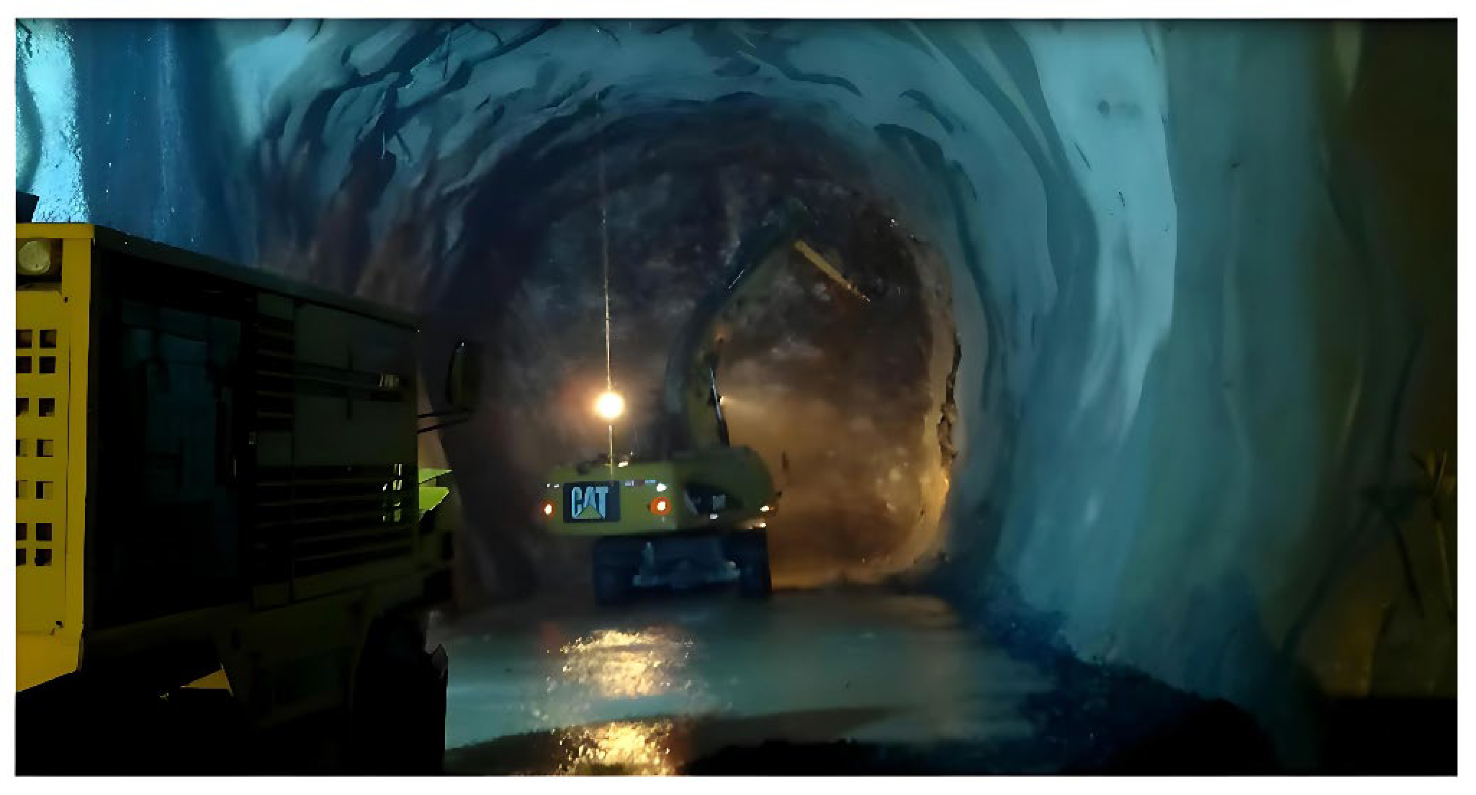
The hydraulic excavator, equipped with a hydraulic hammer and all protection systems, operated for 36 months during the construction stage of the Chaglla hydraulic project’s conduction tunnel. A total of six systems were commissioned, yielding an operational result with only minor incidents involving some mechanical elements. Despite the company’s goal of zero fatalities, there were six fatalities associated with the tunnel construction activity [12], not specifically with scaling. Throughout this period, the excavators were effective for safe operation during tunnel construction; zero fatal accidents were reported directly associated with the scaling of the excavators. Reduced visibility due to long distances and insufficient lighting was a challenge and can be considered an area for improvement (Figure 12).
5. Conclusions
The current study proposed as an alternative scaling method a pack hydraulic excavator and hydraulic hammer, which were viable for scaling mechanically, hydraulically, and functionally, and were intended for intensive use over many years. This setup represented a lower investment compared to specialized equipment, reducing the risk for operators compared to manual or semi-mechanized work with scissor lifts.
The use of protection systems for the hydraulic hammer was essential for its durability under extreme conditions inside tunnels. The fleet of six excavators worked three shifts for 36 months with efficacy, without significant problems or fatalities.
The methodical approach not only addressed the project’s initial constraints but also established a benchmark for future tunnel scaling operations, underscoring the importance of integrating safety, efficiency, and cost-effectiveness into construction methodologies.
The result of this research supports the alternative use of mechanical equipment such as excavators or similar equipment which are being used by the industry in various projects in construction and mining. However, the use of specialized scalers includes additional benefits, deeply researched by manufacturers and the industry, which had to be taken into account to improve the workers’ safety, before alternative solutions.
Credit Author Statement
Yuri Villa: Resources, Writing - original draft, Conceptualization, Methodology, Investigation, Supervision, Data curation, Design. Mariella Carbajal: Validation, Formal analysis, Visualization, Software, Writing - review and editing.
Declaration of Competing Interest
The authors declare that they have no known competing financial interests or personal relationships that could have appeared to influence the work reported in this paper.
References
- A. Kumar Mishra, P. S. Aithal, A. Professor, and M. Bhandari Memorial Academy Nepal, “Job Safety Analysis during Tunnel Construction.” [Online]. Available: https://ssrn.com/abstract=3856137.
- I. Ocak, S. E. Seker, and J. Rostami, “Performance prediction of impact hammer using ensemble machine learning techniques,” Tunnelling and Underground Space Technology, vol. 80, pp. 269–276, Oct. 2018. [CrossRef]
- N. Cardenas Loardo, “Influencia del mantenimiento centrado en la confiabilidad en la disponibilidad mecánica de los equipos Scaler en la Unidad Minera Yauli,” Universidad Nacional del Centro del Perú, 2018, Accessed: Feb. 27, 2024. [Online]. Available: http://repositorio.uncp.edu.pe/handle/20.500.12894/4498.
- E. Dutra, C. José De Oliveira, G. Cordeiro Da Silva, and T. H. Amorim De Souza, “Integrity, Reliability and Failure of Mechanical Systems IRF’2013 MAINTENANCE ON CONDITION AND CORRECTIVE MAINTENANCE: emphasis on asset reliability in industrial sector.”.
- A. B. Delgado Quispe, “Diseño de un conjunto de componentes mecánicos para modificar un elevador telescópico en un desatador de rocas,” Repositorio Institucional UTEC, 2019, Accessed: Jan. 16, 2022. [Online]. Available: https://repositorio.utec.edu.pe/handle/20.500.12815/107#.YeX8DcC-_Mg.mendeley.
- E. Peruano, A. Reglamento De Seguridad, and S. Ocupacional En Minería, “Publicacion Oficial - Diario Oficial El Peruano.”.
- >D. Lock, “Project management,” Project Management, pp. 1–551, Apr. 2013. [CrossRef]
- J. A. Marshall, A. Bonchis, E. Nebot, and S. Scheding, “Robotics in Mining,” Springer Handbooks, pp. 1549–1576, 2016. [CrossRef]
- J. L. T. Florez-Salas, E. M. Ramos-Saira, C. E. Joo-García, R. Ramos-Alave, F. Del Carpio-Delgado, and K. M. Laura-De La Cruz, “Safety and Occupational Health Management System in Mining to Reduce Fatal Accidents in the Mining Industry,” Smart Innovation, Systems and Technologies, vol. 366, pp. 57–67, 2023. [CrossRef]
- J. J. Fonseca Huerta, “Implementación de los riesgos críticos de seguridad para controlar incidentes – accidentes durante la perforación diamantina en la Uea Chungar – Mina Animón de Cia Minera Volcan S.A. año 2017,” Universidad Nacional Santiago Antúnez de Mayolo, 2018, Accessed: Feb. 27, 2024. [Online]. Available: http://repositorio.unasam.edu.pe/handle/UNASAM/2893.
- C. Montorfano and R. Giti Ruberto, “Developing cross passages and safety niches in a rationalized way using remote controlled demolition robots,” Tunnels and Underground Cities: Engineering and Innovation meet Archaeology, Architecture and Art- Proceedings of the WTC 2019 ITA-AITES World Tunnel Congress, pp. 4095–4103, 2019. [CrossRef]
- Hartmann, “Chaglla Hydropower Project Peru Project Stage: Implementation,” 2015. [Online]. Available: www.hydrosustainability.org.
- S. Ahmadi, M. Hajihassani, S. Moosazadeh, and H. Moomivand, “The Open Construction and Building Technology Journal An Overview of the Reliability Analysis Methods of Tunneling Equipment,” vol. 14, pp. 218–229, 2020. [CrossRef]
- U. De, P. De, L. F. De, I. De Minas, I. E. Miguel, and H. Buitron, “Evaluacion del proceso de minado para mejorar productividad de método sublevel caving mecanizado - U.M. Yauricocha,” 2021, Accessed: Feb. 27, 2024. [Online]. Available: http://repositorio.uncp.edu.pe/handle/20.500.12894/8574.
- M. Giraldo and J. Badillo, “Implicancias técnicas y económicas de los accidentes mortales en la minería peruana Technical and economics consequences of fatal accidents in peruvian mining,” vol. 18, pp. 97–107, 2015.
- Y. Jinrong, M. Claudia, K. Sharique, and G. Venkatesh, “A case study on design and construction of mined tunnel in challenging ground conditions in Singapore,” in Expanding Underground - Knowledge and Passion to Make a Positive Impact on the World- Proceedings of the ITA-AITES World Tunnel Congress, WTC 2023, CRC Press/Balkema, 2023, pp. 1979–1987. [CrossRef]
- Luis and L. Chahuayo, “Control basado en indicadores claves de desempeño en la gestión de maquinaria pesada en la excavación de túnel,” Universidad Peruana Los Andes, Oct. 2022, Accessed: Feb. 27, 2024. [Online]. Available: http://repositorio.upla.edu.pe/handle/20.500.12848/5000.
- H. Lingard and S. Rowlinson, “Occupational health and safety in construction project management,” Occupational Health and Safety in Construction Project Management, pp. 1–387, Jan. 2004. [CrossRef]
- OSINERMING, “Boletín Informativo de la Gerencia de Supervisión Minera octubre-diciembre 2023,” 2023.
- M. Giraldo and J. Badillo, “Implicancias técnicas y económicas de los accidentes mortales en la minería peruana Technical and economics consequences of fatal accidents in peruvian mining,” 2015.
- M. Sari, A. S. Selcuk, C. Karpuz, and H. S. B. Duzgun, “Stochastic modeling of accident risks associated with an underground coal mine in Turkey,” Saf Sci, Jan. 2009. [CrossRef]
- C. Rivera Domínguez, I. Villanueva Martínez, P. María, P. Peña, and A. R. Ochoa, “Analysis and evaluation of risks in underground mining using the decision matrix risk-assessment (DMRA) technique, in Guanajuato, Mexico,” 2019. [CrossRef]
- V. K. Karra, “Analysis of non-fatal and fatal injury rates for mine operator and contractor employees and the influence of work location,” J Safety Res, vol. 36, no. 5, pp. 413–421, Jan. 2005. [CrossRef]
- Kearney, “Occupational fatalities among grounds maintenance workers in the United States (2016−2020),” Am J Ind Med, vol. 66, no. 9, pp. 750–758, Sep. 2023. [CrossRef]
- Osinerming, “Central hidroeléctrica chaglla (456 mw),” p. 2, 2020.
- S. B. Mickovski and G. Pirie, “Practical methodology for the design and management of instability in hard rock tunnels,” 17th European Conference on Soil Mechanics and Geotechnical Engineering, ECSMGE 2019 - Proceedings, vol. 2019-September, Sep. 2019. [CrossRef]
- F. Wood and G. Ambrosii, “Design challenges in the Chaglla hydroelectric scheme,” Rock Mechanics Contributions and Challenges: Proceedings of the 31st U.S. Symposium, pp. 67–74, Dec. 2020. [CrossRef]
- Atlas Copco, “SB 302 SC and SB 452 SC Scaler Stronger, more reliable,” Brochure of SB452SC, 2010.
- M. Journal, “Atlas Copco ’ s Hydraulic Breaker Care Service Offers Scheduled...,” no. May, 2007.
- Dynaset, “USER MANUAL HYDRAULIC PISTON COMPRESSORS,” Dynaset, p. 58, 2013.
- Caterpillar, “Specalog for M313D Wheel Excavator AEHQ6993-01,” 2014.
- W. Liu, Q. Zeng, W. Qin, L. Wan, and J. Liu, “Lifetime Reliability of Hydraulic Excavators’ Actuator,” IEEE Access, vol. 11, pp. 117670–117684, 2023. [CrossRef]
- “CordovaV_R”.
- C. Alexander Fleming No, “MODIFICACIÓN DEL ESTUDIO DE IMPACTO AMBIENTAL DEL PROYECTO CENTRAL HIDROELÉCTRICA CHAGLLA VOLUMEN I EIA Preparado para: Preparado por,” 2010.
- Caterpillar, “Cat-Performance-Handbook-from-VST-fuel-consumption-2022-12-09T21-20-09,” 2022.
- Miller A, “CDC - Mining - Rock Falls - Preventing Rock Fall Injuries in UG Mines - NIOSH.” Accessed: Oct. 04, 2024. [Online]. Available: https://www.cdc.gov/niosh/mining/works/coversheet1835.html.
- W. Liu, Q. Zeng, L. Wan, J. Liu, and H. Dai, “Reliability Importance Measures considering Performance and Costs of Mechanical Hydraulic System for Hydraulic Excavators,” J Sens, vol. 2022, 2022. [CrossRef]
- Caterpillar, “Wheel Excavator ®,” Brochure of Wheel Excavator M313D, no. Iso 9249, pp. 1–32, 2000.
- B. J. Morton and T. Writer, “New Technology, Regulations Prompt Innovation,” no. December, pp. 42–48, 2021.
- Caterpillar, “ARTICULATED TRUCKS 1 BACKHOE LOADERS 2 DRILLS 3 ENGINES 4 FOREST PRODUCTS 5 HIGHWALL MINING SYSTEM 6 HYDRAULIC EXCAVATORS-Front Shovels • Hydraulic Excavators,” 2019.
- BROKK, “Backing The Bot,” 2012. [Online]. Available: www.brokk.com.
- A. Copco, “Manual de Instrucciones SB,” no. 9800, pp. 2013–2015, 2017.
- K. B. Bautechnik, “Operating manual Krupp ContiLube ® II,” no. 3002860, 2001.
- E. Peruano, A. Reglamento De Seguridad, and S. Ocupacional En Minería, “Publicacion Oficial - Diario Oficial El Peruano.”.
- A. Copco, “Solid productivity you can rely on !,” 2014.
- Daniel dit Rabih et al., “Real time simulation of hydraulic systems using multibody dynamics analogy,” 2017, McGill University. Accessed: Mar. 18, 2024. [Online]. Available: https://escholarship.mcgill.ca/concern/theses/qn59q6824?locale=en.
- Y. Villa, T. Vook, J. L. Villa, P. Carbajal, L. Barrera, and M. Florez, “STRUCTURAL AND MODAL ANALYSIS OF ADAPTER PLATES FOR HYDRAULIC HAMMERS AND SKID STEERS UNDER REAL WORK CONDITION,” Ingenius, vol. 2022, no. 28, pp. 92–99, 2022. [CrossRef]
- Atlas Copco, “ContiLube ® II,” Atlas Copco, 2000.
- Atlas Copco, “Spare parts list Hydraulic breakers,” 2012.
- A. Copco, “Spare parts list,” Manual de Partes SB, no. 9800, 2010.
Figure 1.
Criticality analysis of equipment [4]. MTBF (Mean time between failures in hours), MTTR (Mean time to repair in hours), and for Production Impact, Repair Cost, Safety impact, Environmental Impact (A relative score where 0 means lower impact and 40 higher impact).
Figure 1.
Criticality analysis of equipment [4]. MTBF (Mean time between failures in hours), MTTR (Mean time to repair in hours), and for Production Impact, Repair Cost, Safety impact, Environmental Impact (A relative score where 0 means lower impact and 40 higher impact).
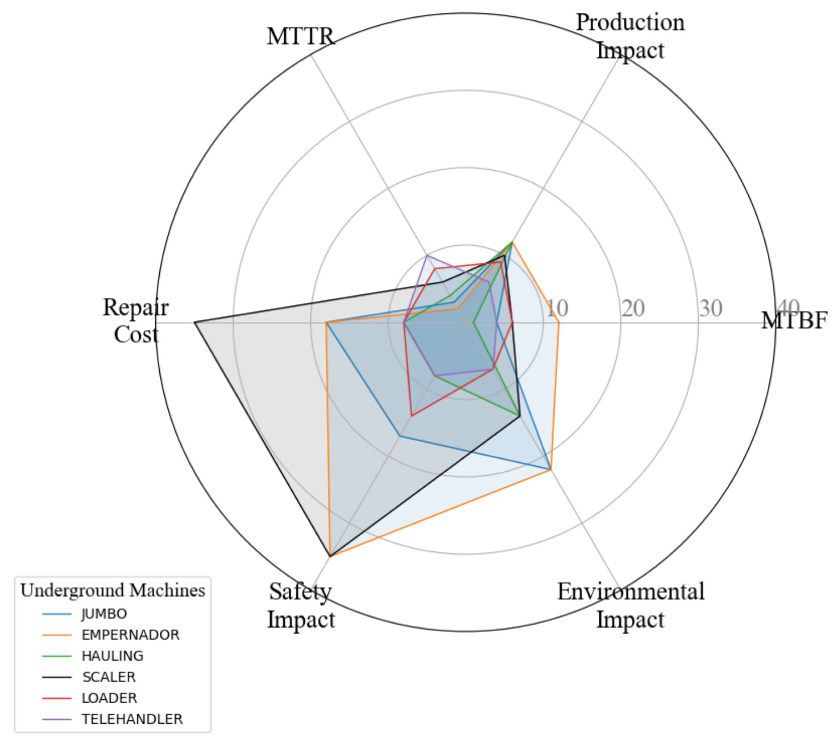
Figure 2.
Scaling activity in drilling and blasting cycle.
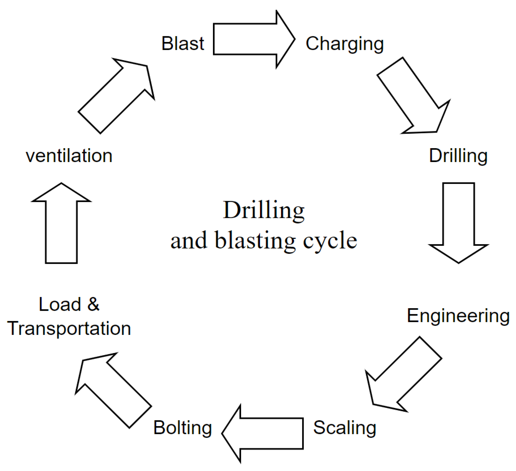
Figure 3.
Rockfall fatalities statistics, MINEM from 2006 to 2023.
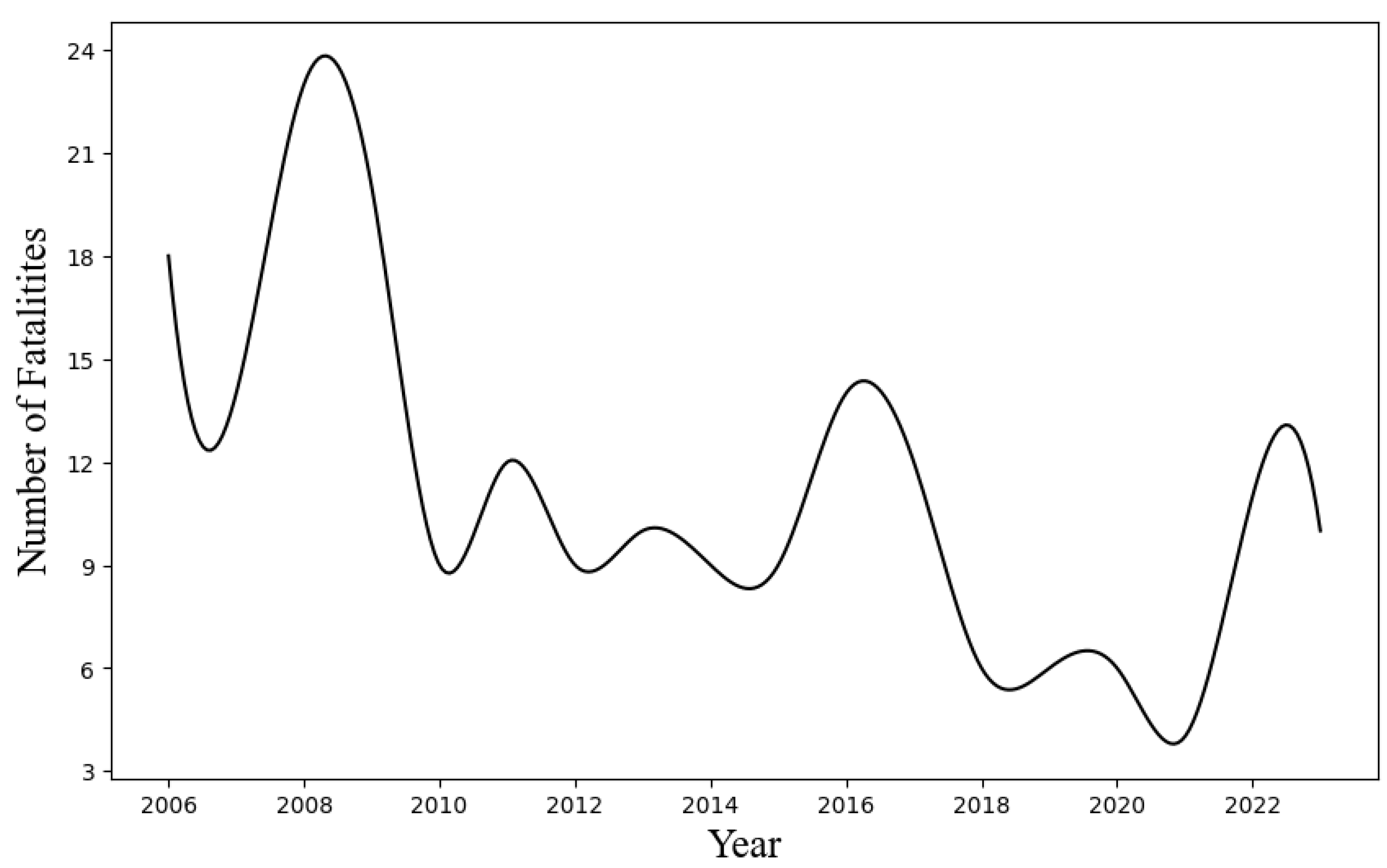
Figure 4.
Rockfall Fatalities Poisson distribution.
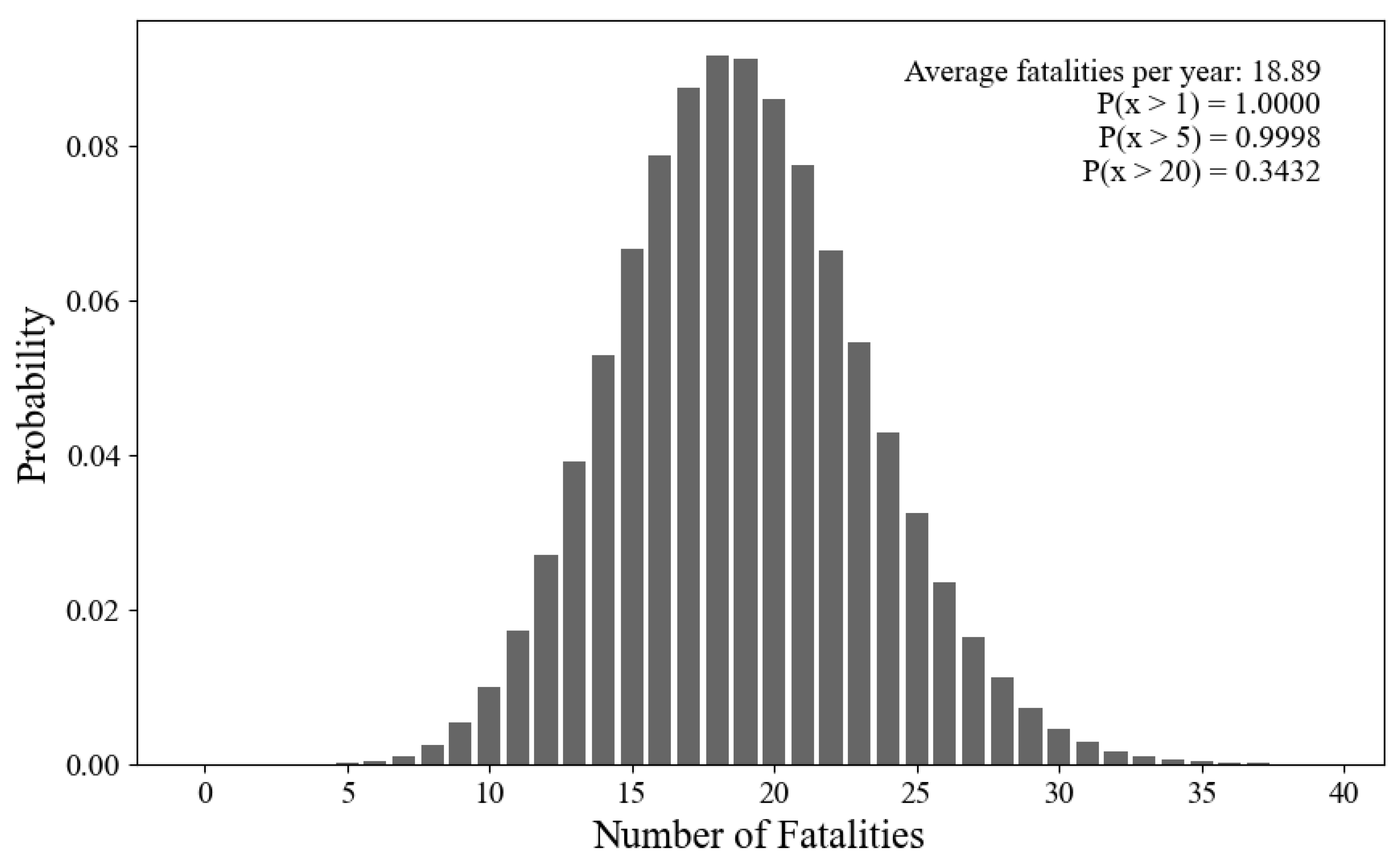
Figure 5.
Comparison of reliability and availability between Scalers and Excavators.
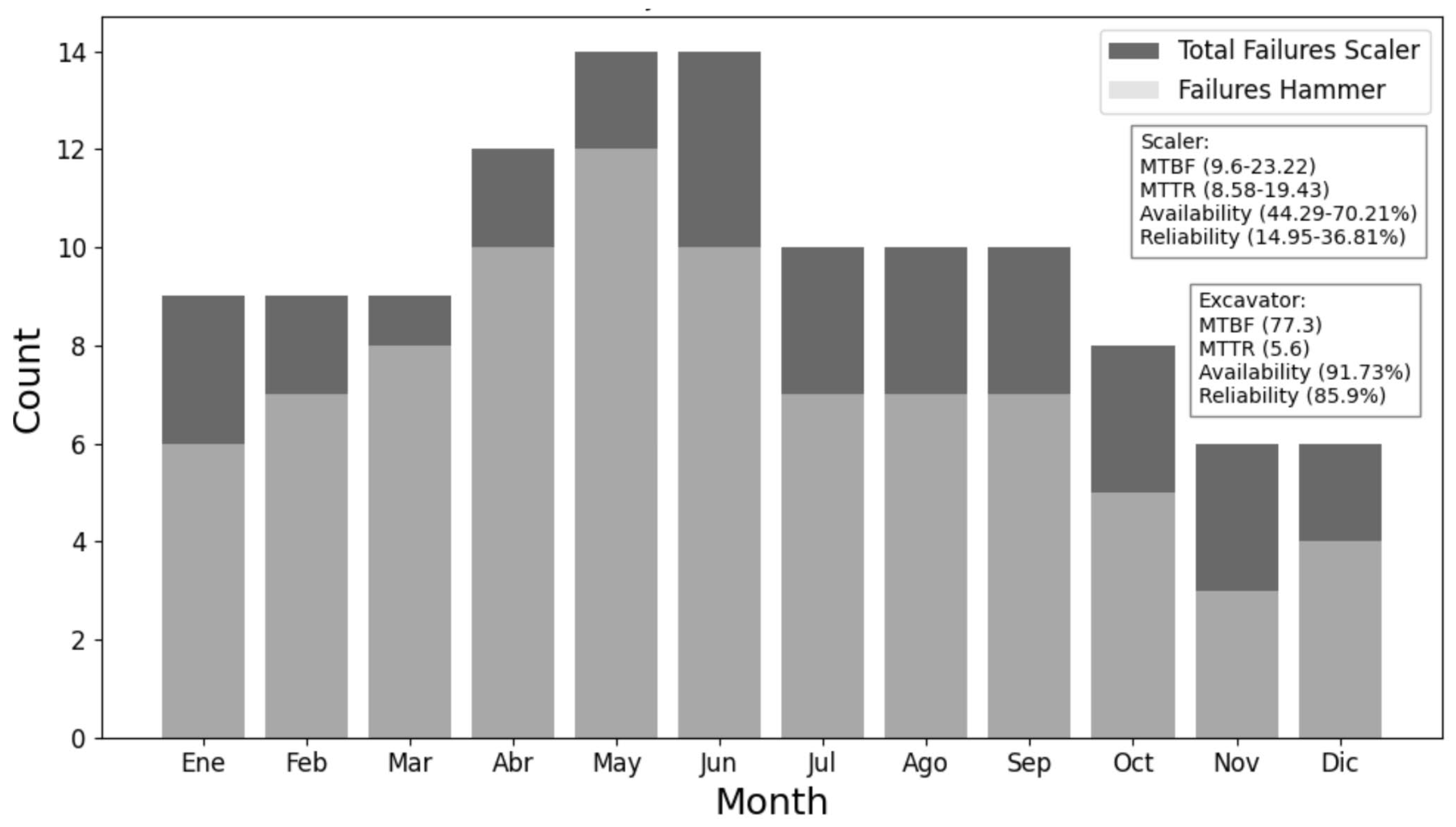
Figure 6.
Decision-making criteria for the excavator and hydraulic hammer for scaling.
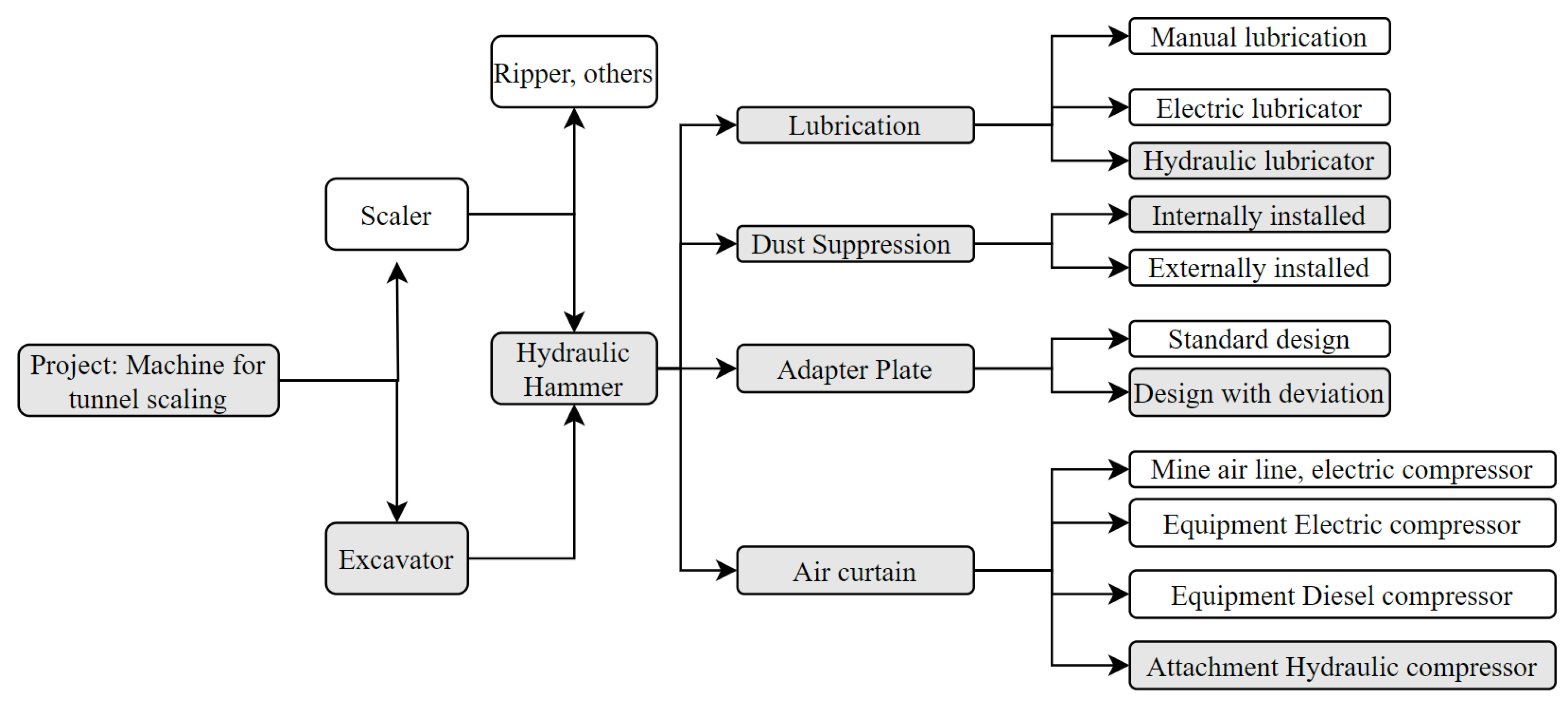
Figure 7.
Maximum vertical reach and horizontal position of the CAT M313D with a hydraulic hammer and the work position.
Figure 7.
Maximum vertical reach and horizontal position of the CAT M313D with a hydraulic hammer and the work position.
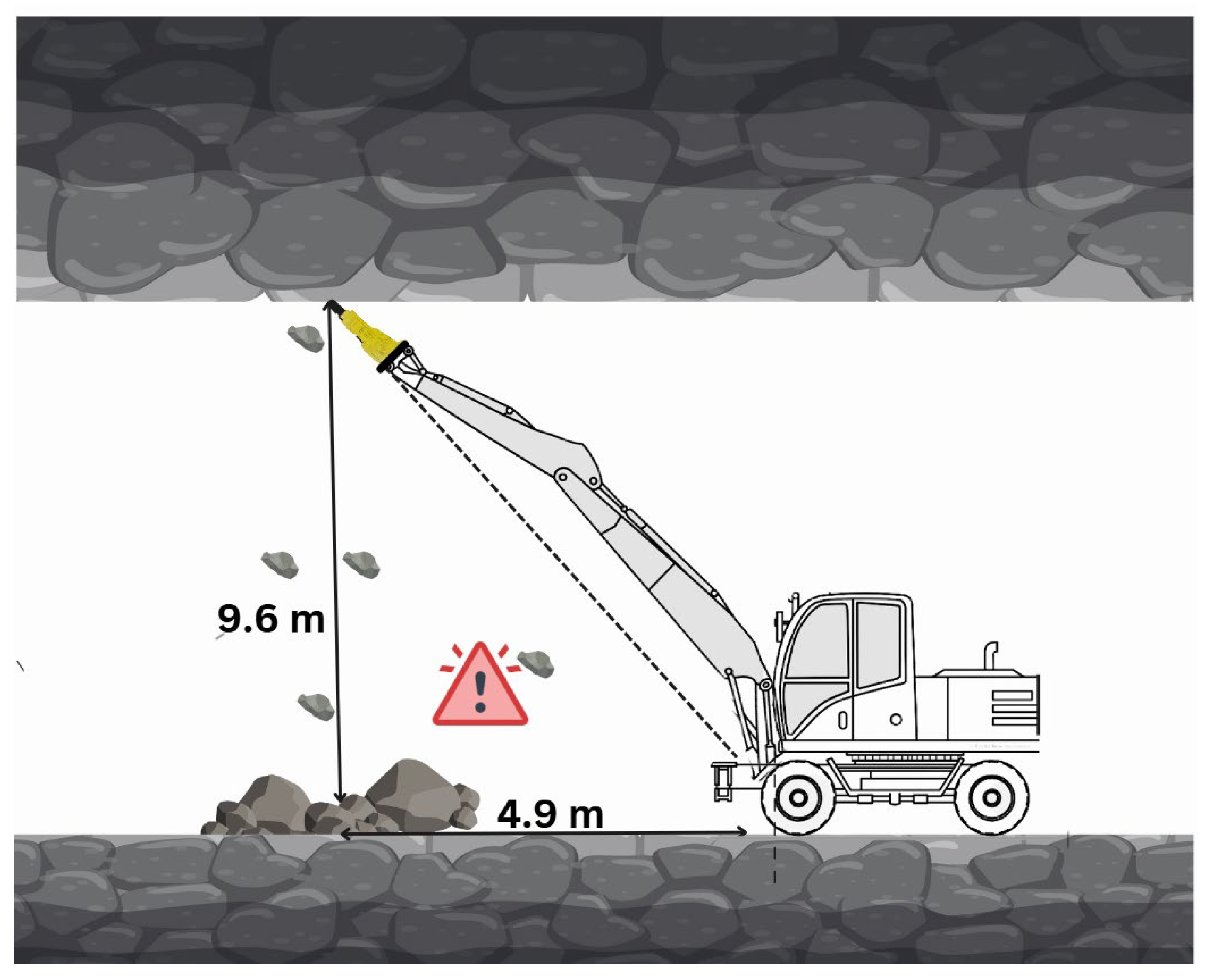
Figure 8.
Hydraulic flow chart for operation of hydraulic hammer and protection systems, where Q is the flow rate and P the pressure.
Figure 8.
Hydraulic flow chart for operation of hydraulic hammer and protection systems, where Q is the flow rate and P the pressure.
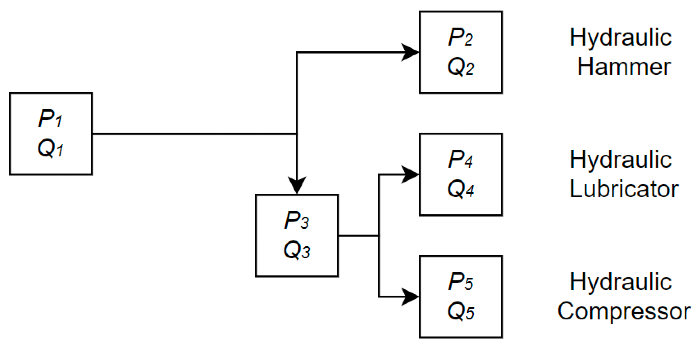
Figure 9.
a) Lubrication lines installed connections, and b) Contilube II system installed over the excavator and connected to the hydraulic lines.
Figure 9.
a) Lubrication lines installed connections, and b) Contilube II system installed over the excavator and connected to the hydraulic lines.
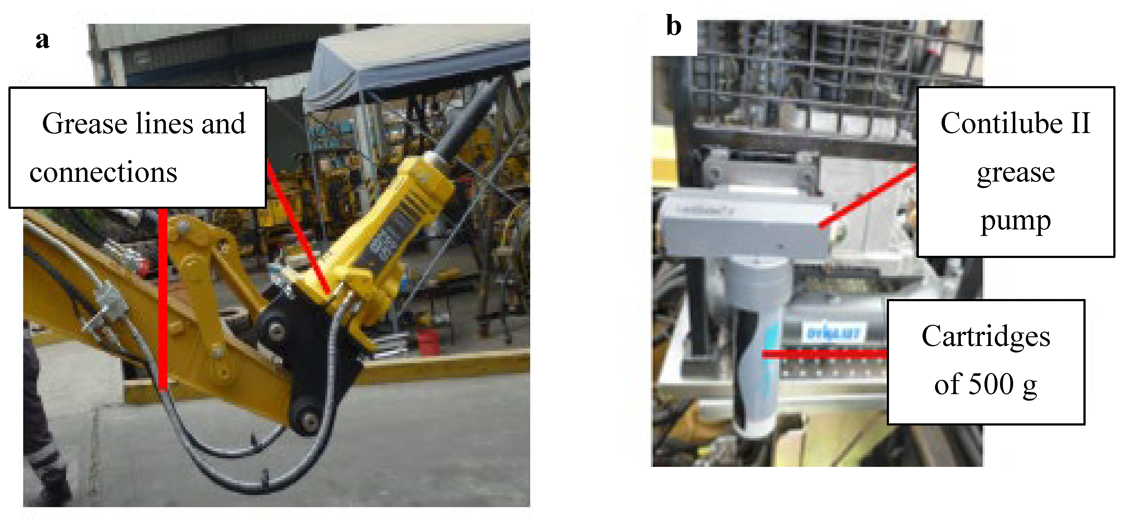
Figure 10.
Water spraying lines installed.
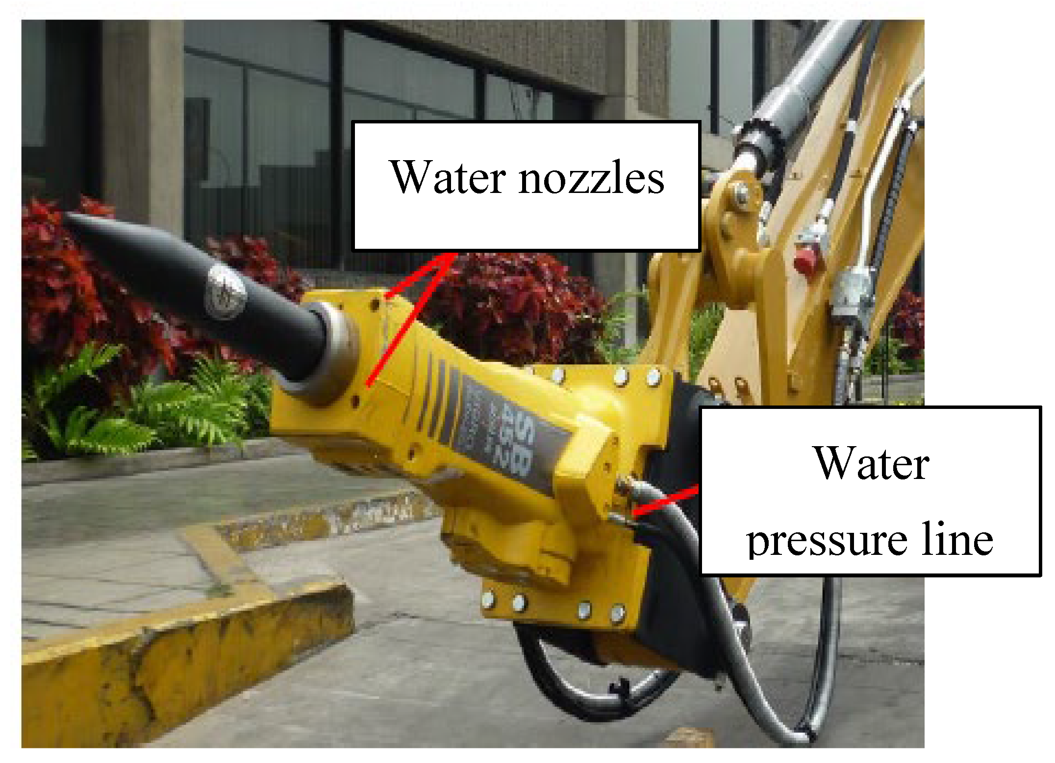
Figure 11.
a) Hydraulic compressor installed with the air pressure system, and b) Hammer reach in a vertical operation position with an adapter plate with negative slope.
Figure 11.
a) Hydraulic compressor installed with the air pressure system, and b) Hammer reach in a vertical operation position with an adapter plate with negative slope.
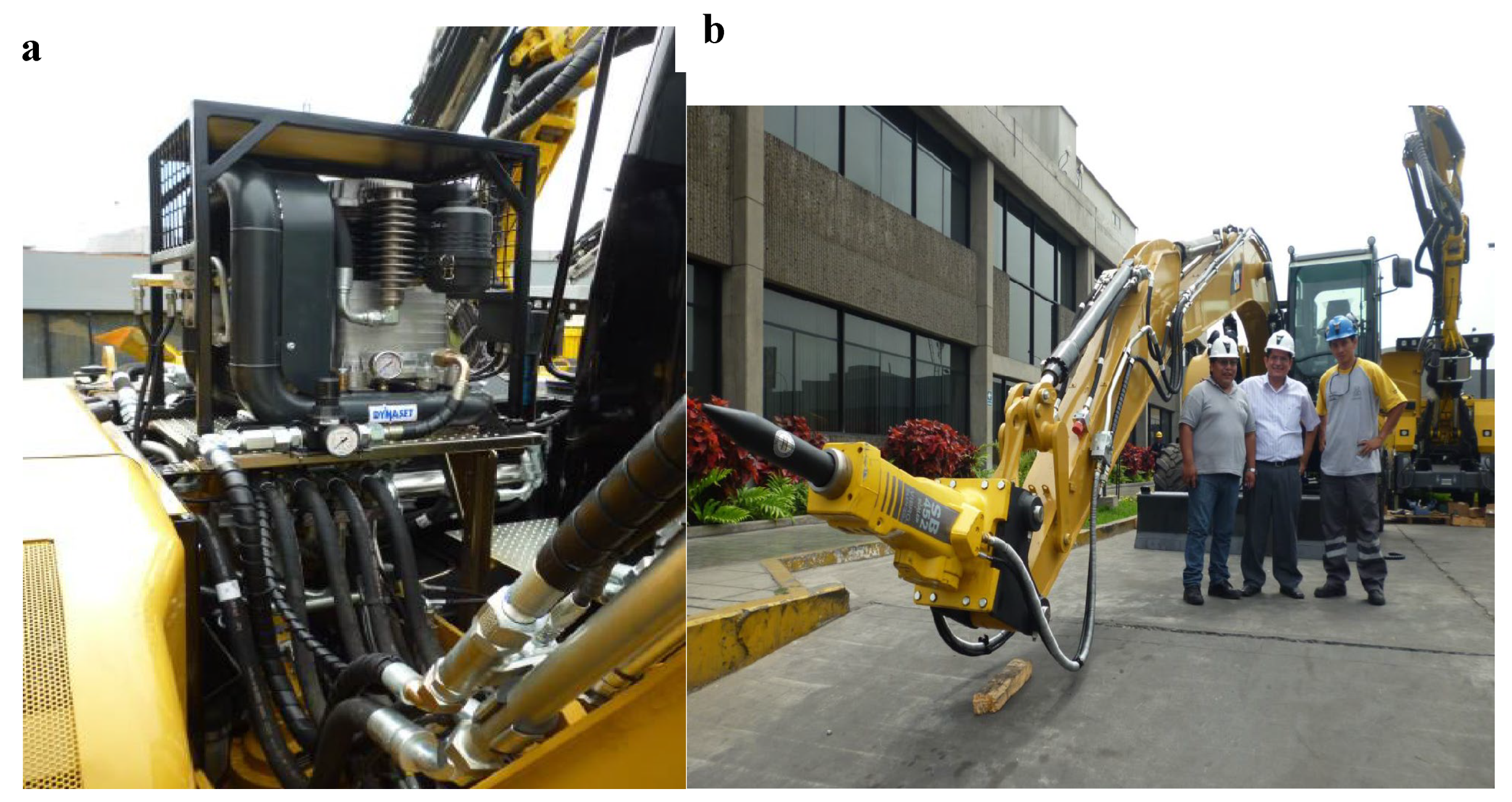
Figure 12.
Excavator Operation and commissioning in the hydraulic tunnel.
Disclaimer/Publisher’s Note: The statements, opinions and data contained in all publications are solely those of the individual author(s) and contributor(s) and not of MDPI and/or the editor(s). MDPI and/or the editor(s) disclaim responsibility for any injury to people or property resulting from any ideas, methods, instructions or products referred to in the content. |
© 2025 by the authors. Licensee MDPI, Basel, Switzerland. This article is an open access article distributed under the terms and conditions of the Creative Commons Attribution (CC BY) license (http://creativecommons.org/licenses/by/4.0/).
Copyright: This open access article is published under a Creative Commons CC BY 4.0 license, which permit the free download, distribution, and reuse, provided that the author and preprint are cited in any reuse.


