Submitted:
11 March 2025
Posted:
13 March 2025
You are already at the latest version
Abstract
Existing supply and exhaust systems of centralised heating, ventilation, and air conditioning under certain conditions not only do not protect against infection, but also serve as a source of accumulation and spread of pathogenic microorganisms (viruses, bacteria, etc.). The aim of this work was to develop a method for cleaning and disinfecting air from aerosolised pathogenic microflora in centralised building ventilation systems with out significant reconstruction and changes in technological parameters. For this purpose, a complex of complementary physical and chemical methods was used, including analytical and experimental studies using the theory of electro-gas dynamics of dispersed systems and involving methods of raster scanning microscopy, methods of comparing the same quality indicators of samples, and initial samples. The optimal technological parameters of the processes to increase the efficiency of air disinfection and purification by plasma photocatalysis were determined. The authors propose technical solutions to improve the energy efficiency of a pilot experimental installation for complex air purification and disinfection of a wide class of air pollutants in building supply and exhaust ventila- tion systems. The proposed solutions are aimed at reducing the energy consumption for air purification and disinfection while maintaining the required air quality in the premises.
Keywords:
aerodispersion
; air purification
; plasma chemistry
; photocatalysis
; pathogenic microflora
; efficiency
1. Introduction
The COVID-19 pandemic has starkly highlighted the critical need for innovative and scalable disinfection technologies to mitigate the transmission of infectious diseases through contaminated surfaces and air. Current gold standard disinfection methods often rely on energy-intensive and chemically intensive processes, raising concerns about environmental sustainability and potential long-term health impacts. Advanced oxidation processes (AOPs), particularly photocatalysis, have emerged as a promising alternative for disinfection. Photocatalysis leverages reactive oxygen species (ROS) to disrupt viral capsids and render pathogens noninfectious. However, several critical knowledge gaps impede the widespread adoption of this technology. A more comprehensive understanding of the photoinactivation mechanisms of viruses, including their rapid mutagenicity and post-treatment viability, is essential for optimising photocatalytic disinfection protocols. While photocatalytic oxidation [1,2] offers an attractive solution for air purification by effectively decomposing diverse air pollutants into non-toxic byproducts, translating this technology into commercially viable photocatalytic reactors presents significant engineering challenges. The development of a robust, scalable, and efficient method for immobilizing the photocatalyst onto a suitable support material remains the primary obstacle. Achieving successful and durable immobilisation under ambient conditions would represent a significant advance, accelerating the commercialization and deployment of photocatalytic disinfection technologies for both surface and air decontamination. Although photocatalytic air purification offers numerous advantages, its practical application is often hampered by limitations, such as a relatively slow purification rate. Combining photocatalysis with complementary technologies, such as adsorption, photothermal catalysis (PTC), or plasma catalysis, presents a promising avenue for synergistic enhancement. Such hybrid approaches can improve overall treatment performance by, for example, facilitating the rapid capture of target compounds on the catalyst surface. PTC, in particular, combines the high efficiency and durability of thermal catalytic oxidation with the benefit of a lower energy consumption. Similarly, integrating plasma treatment can promote the degradation of air pollutants, while photocatalysis minimises the formation of potentially harmful byproducts. Despite these potential benefits, hybrid processes remain in their early stages of development [3,4], necessitating further in-depth research to fully elucidate the underlying synergistic mechanisms and address the practical engineering challenges associated with their implementation. Hybrid technologies offer a promising approach for integration within heating, ventilation and air conditioning (HVAC) systems to significantly mitigate the spread of viral infections, pathogenic microflora and molecular air pollutants [5,6,7].
Public and administrative buildings commonly use supply and exhaust HVAC systems, often incorporating mechanical ventilation with coarse filters and rotary heat recovery devices. Although the main function of these HVAC systems is to maintain the indoor microclimate parameters within defined specifications [8,9,10], under certain operating conditions, they can inadvertently act as reservoirs and vectors for the accumulation and dissemination of airborne pollutants [11,12] (Figure 1).
Maintaining safe and healthy indoor air quality (IAQ) in buildings presents a complex challenge, as it is influenced by a multitude of interacting factors [13]. These include the intended use of the space, the architectural design and the specific characteristics of its ventilation system, the operating protocols employed within the building, and the prevailing climatic conditions. Consequently, effective mitigation strategies require the careful selection and appropriate integration of advanced air purification and disinfection technologies within heating, ventilation, and air conditioning systems (HVAC) [14].
The primary source of airborne pathogens within buildings is typically infected occupants, whose respiratory activities generate infectious aerosols [15]. Pathogens may be introduced via outdoor air intakes, especially in regions with compromised air quality. HVAC systems, while often employing recirculation for energy efficiency, can inadvertently contribute to the redistribution of these pathogens [16]. If recirculated air contains viable infectious agents, they can be drawn into the return air ductwork and subsequently disseminated throughout the building via the supply air stream. While filters are standard HVAC components, their efficacy against all pathogens, particularly smaller viral particles, is limited [17]. Furthermore, the efficacy of various available air purification methods (Figure 2) within HVAC systems can be substantially diminished by the limited residence time of aerosolised particles within the purifier's active zone under typical air exchange conditions.
A critical aspect of the performance of the HVAC system is filtration. Suboptimal filter selection, such as using filters with an inadequate Minimum Efficiency Reporting Value (MERV) rating for the target pathogens, can significantly compromise the filtration barrier. Similarly, improper maintenance, including infrequent filter replacement or incorrect installation, can allow pathogens to penetrate the filter and enter the recirculated airstream. Furthermore, filters themselves can become reservoirs for microbial growth if not properly maintained, potentially exacerbating the problem. Beyond filtration, airflow dynamics and system hygiene play a crucial role in pathogen distribution. Poorly balanced airflow, often a consequence of suboptimal ductwork design or diffuser placement, can create stagnant zones that facilitate pathogen accumulation or, conversely, promote their widespread dissemination. Insufficient ventilation, characterised by an inadequate supply of fresh air, further compounds this risk by allowing pathogens at accumulate to higher concentrations. Inadequate system hygiene, including contaminated conduits and other components such as cooling coils and drain pans, promotes microbial proliferation and can contribute to the overall burden of airborne pathogens.
Photocatalytic and plasmochemical air disinfection methods, frequently coupled with filtration systems for the removal and ozone mitigation, have gained significant traction in contemporary applications due to their potential for the control of broad-spectrum pollutants [18,19]. However, translating these technologies, particularly photoplasma catalytic methods, to the dynamic aerodisperse flows characteristic of centralised ventilation systems presents substantial challenges [27,28]. Plasmochemical disinfection methods are inherently governed by the specific mechanisms and kinetics of the underlying plasmochemical reactions, which are further influenced by the unique chemical processes occurring within low-temperature plasmas and plasma jets as the aerodisperse flows pass through them [21]. A more comprehensive understanding of these complex interactions is crucial for optimising the performance and reliability of these technologies in real-world HVAC applications.
Low-temperature plasma, generated via high-voltage discharge, interacts with these aerodisperse flows, and the discharge parameters directly influence the interaction time. Consequently, the design of the plasma-chemical treatment unit plays a critical role, directly affecting the intensity and duration of the plasma interaction with organic molecules present in the air stream. A common by-product of plasma-based air treatment is the generation of excess ozone, which requires its reduction to levels below established permissible limits (eg, 0.1 mg/m³ for occupational exposure [29,30]. The efficacy of ozone abatement depends on the specific destruction mechanism employed, whether photolytic, thermal or catalytic, each exhibiting distinct influencing factors [31,32]. For instance, the efficiency of catalytic ozone decomposition is modulated by the composition of the ozone-gas mixture, the design and contact surface area of the adsorber, the intensity of radiation (if applicable), temperature, humidity, airflow velocity, and the surface properties of the catalyst. Integrating photocatalytic filters within air purification systems offers several compelling advantages, including energy efficiency (low specific energy consumption), environmental benignity (decomposition into harmless by-products), and simplified maintenance requirements.
Finally, the efficacy of photocatalytic air purification is critically dependent on the confluence of factors related to the design and operation of the photocatalytic unit. The selection and strategic placement of the source of ultraviolet (UV) radiation is paramount, as the intensity and spectral characteristics of UV light directly influence the activation of the photocatalyst and the subsequent generation of reactive species responsible for pollutant degradation [18,29]. Furthermore, the aerodynamic resistance of the unit plays a significant role, impacting the airflow patterns and the residence time of pollutants within the reactor, thus affecting the overall purification efficiency. The material properties of the catalyst support matrix, including its composition and surface modification techniques used for photocatalyst immobilization, are also crucial considerations [33,34,35,36,37]. These parameters influence the accessibility to pollutants, the rate of adsorption, and the efficiency of the photocatalytic reaction. A comprehensive understanding of the coupled heat and mass transfer phenomena within the porous catalyst structure is essential for optimising reactor performance [38,39]. Although energy conservation within HVAC systems has traditionally been approached through recirculating air exchange schemes incorporating rotary heat recoverers [40,41], recent public health crises have led to a reevaluation of these practices. Recommendations to limit the operation of the air conditioning system and minimize or eliminate indoor air recirculation have been implemented in some regions due to concerns about the transmission of airborne diseases. The absence of a harmonised international standard for HVAC systems that explicitly incorporates anti-pandemic measures underscores the need for further research and collaborative efforts to balance energy efficiency, indoor air quality, and public health considerations.
This article addresses the pressing need for effective air purification and disinfection strategies within building ventilation and air conditioning (HVAC) systems, particularly in light of increasing concerns about airborne transmission of infectious diseases. The prevalence of centralised ventilation systems in modern buildings, while offering advantages in terms of climate control and energy efficiency, can also inadvertently contribute to the rapid dissemination of airborne pathogens. Current approaches often do not provide adequate protection against these risks, highlighting a critical gap in existing HVAC technologies. Therefore, this work aims to develop and evaluate novel air purification and disinfection modules that integrate plasma chemistry and photocatalysis for seamless integration into centralised HVAC systems without requiring extensive system reconstruction. The overarching goal is to achieve a significant reduction in the pathogenic microflora, thereby minimising the risk of infection and contributing to a healthier indoor environment. This research is particularly relevant given the recent global health crises, which have underscored the vulnerability of indoor environments to airborne transmission and the urgent need for improved air disinfection strategies.
2. Results
2.1. Pilot-Experimental Installation
A pilot-experimental installation was specifically designed and constructed to mimic the operational conditions of a centralised HVAC system. This installation was characterised by its modular design, incorporating autonomous functional units strategically positioned at the intersection of air ducts to replicate representative airflow dynamics. This design allowed for the sequential air treatment, with each module targeting specific classes of pollutants.
Using a modular design, the centralized HVAC system was engineered to allow flexible configurations and seamless integration of additional air purification technologies. The placement of functional modules at air duct intersections was meticulously planned to replicate representative airflow dynamics and maximise contact between the air stream and purification elements. To allow precise control and data acquisition, the installation was equipped with a suite of sensors that continuously monitor airflow rate, pressure drop, temperature and humidity. Figure 3 shows the structural layout of the installation.
The system was constructed using a modular architectural approach. This design principle facilitates ease of reconfiguration, enabling the integration of supplementary air purification technologies as needed. The modularity also allows for targeted maintenance and replacement of individual components, minimising system downtime and maximizing operational efficiency. The functional modules were strategically placed at the intersection points of the air ducts. This placement was deliberate, with the aim of replicating the airflow dynamics and ensuring optimal contact between the air flow and the purification modules. This configuration ensures that air passing through the ventilation system is forced to pass through the purification modules. Thus, maximise the efficiency of the air cleaning process. The installation was equipped with a comprehensive suite of sensors designed to monitor critical operational parameters. These included sensors for airflow rate measurement, providing real-time data on the volume of air passing through the system; differential pressure measurement, allowing for the assessment of aerodynamic resistance across each module; temperature and relative humidity monitoring, ensuring accurate control and documentation of environmental conditions within the system. Structurally, the installation comprised autonomous functional modules (Figure 4) strategically positioned within the cross-section of air ducts to ensure representative airflow dynamics. Each module was designed to address a specific class of pollutants, employing distinct operational principles. Plasma-chemical module designed for the decomposition of volatile organic compounds (VOCs) and other organic pollutants. The module was engineered to operate at ambient temperatures, facilitating the conversion of organic compounds into carbon dioxide (CO2) and water (H2O).
The products of high-voltage electric discharge, including ozone (O3), atomic oxygen (O), excited molecular oxygen (O2), hydroxyl radicals (OH), and ions, exhibit a high oxidative capacity. The generated hydroxyl radicals and ozone react with organic molecules through hydrogen abstraction, forming alkyl radicals that are subsequently rapidly oxidized in the air stream. This mechanism facilitates the degradation of a wide range of organic compounds, including those constituting living organisms. Critically, it effectively disrupts bacterial capsules and cell walls of pathogenic microorganisms. Furthermore, the bombardment of the membranes of organic molecules with electrons upon contact with the ionised plasma volume contributes to their structural breakdown.
Within the photocatalytic (PC) module, the air purification process proceeds through the following stages [42]:
- − adsorption of microorganisms and harmful substance molecules onto the PC surface, coupled with the generation of oxidising agents on the photocatalyst surface under UV irradiation (365-405 nm);
- − degradation of the entire molecular structure of microorganisms via interaction of their organic matter with photoinduced radicals on the catalyst surface, resulting in complete inactivation and deactivation of gas-phase compounds and aerosols at the molecular level;
- − complete conversion of microbial or other hazardous pollutant substances into elementary inorganic compounds, yielding harmless byproducts.
Field tests of the developed equipment, which was installed in the existing ventilation system with a rotary recuperator and forced air injection, were carried out in the autumn-winter period in a production room with the size of 24×12 m and a height of 6 m. The air exchange rate was provided at the level of 2. The maximum number of workers who were in the production room at the same time was 12 people. The average temperature and relative humidity in the room were 14-16 ° C and 65-70%, respectively.
The disinfection system were carried out for 10 days during working hours. During the operation of the plasma chemical and photocatalytic air disinfection modules, air sampling for the culture medium was carried out at four points of the room at a height of 1.5 m from the floor. For a comparative analysis of the microflora content in the air, the samples with the largest contamination area after two days of exposure in the thermostat at 37 ° C were selected.
2.1.1. Effect of Electrode Geometry and Inter-Electrode Distance on Corona Discharge Characteristics
To ensure stable corona discharge, various corona electrode geometries were evaluated. The optimal ionisation and electric field intensity within the plasma-chemical treatment zone were achieved using saw-toothed corona electrodes. The relationship between current and applied voltage across the corona electrodes was determined at varying interelectrode distances. The stable operating parameters of the low temperature plasma generator were established by analysing its voltage-current characteristics (VAC) (Figure 5a).
The operating range of the high-voltage capacitor, which allows stable corona discharge and air-gap ionization, was determined based on the basis of the arc gap (L) between the electrodes. The high voltage was increased until arc ignition, indicating air gap breakdown and cessation of ionisation. Points A on the VAC represent the onset of arc gap breakdown as a function of inter-electrode distance and applied voltage.
Experimental results demonstrated a significant influence of the interelectrode distance on the stability of the low-temperature plasma. An air gap length of 20–25 mm was established to broaden the stable corona discharge range at varying high-voltage levels supplied to the plasma generator.
Experimental results demonstrated that varying the high voltage applied to the plasma generator allows the regulation of ozone content in the airflow. The dependence of ozone generation within the voltage range of 5–25 kV is accurately approximated (R²=0.98) by a second-order polynomial, with an inflection point in the region of 20 to 23 kV. This indicates that ozone generation decreases beyond 20 kV (Figure 5b).
2.1.2. Adsorbent-Catalyst Characteristics in the Air Stream Purification Adsorption-Catalytic Module
The catalytic activity of the adsorbent is intrinsically linked to the development of its granular surface area. Analysis of the adsorption-catalytic granular layer (Figure 6) revealed a favourable distribution of aggregates formed from the mixture of components, resulting in a predominantly mesoporous structure with an accessible internal surface. This structure facilitates efficient mass transfer of ozone-containing aerodispersed species and reaction products.
The Brunauer-Emmett-Teller (BET) method determined a maximum specific surface area of 280 m²/g, enhancing the adsorption capacity and catalytic reaction rates. Furthermore, microanalysis of the surface of the adsorption-catalytic granule, as depicted in the spectrum (Figure 6), revealed the elemental composition presented in Table 1.
The percentages of key elements varied at different measurement points, indicating the distribution of the components within the granule. In particular, carbon (C) was the predominant element, with varying levels of oxygen (O), aluminium (Al), silicon (Si) and calcium (Ca) also detected. Variability in elemental composition at different points suggests a heterogeneous distribution of components within the granule, which may influence its catalytic properties.
2.1.3. Characterisation of Deposited TiO2 Catalyst Layer and Aerodynamic Drag Analysis
The structural and topological characteristics of the AEROXIDE® TiO2 P25 catalyst layer deposited on the fibers of the polymer matrix-carrier were evaluated using scanning electron microscopy (SEM) at an accelerated voltage of 10 kV (Figure 7).
2.1.3.1. Catalyst Layer Morphology
The PP matrix modification technology resulted in a uniformly rough coating surface (Figure 8a,b). The deposited catalyst layer exhibited a thickness ranging primarily from 5 to 10 μm (Figure 8c). The texture was corpuscular, formed by aggregated titanium dioxide particles with sizes between 80 and 160 nm.
The analyses demonstrated that the monodisperse aggregates formed a predominantly monopore space. This specific surface texture maximised the accessibility of UV radiation to the titanium dioxide particles, thereby enhancing the photoreaction surface area.
2.1.3.2. Aerodynamic Drag Analysis
The proposed geometric parameters of the filter were designed to increase the contact surface area while minimising the aerodynamic drag of the PC module. A comparative analysis of the modified PC filter, both with and without installed UV emitters, was performed. The results showed an increase in aerodynamic drag by a factor of 1.3 to 2, depending on the air load (Figure 9).
This increase was attributed to the presence of the UV emitters and their associated support structures within the filter module.
2.1.4. Microbiological Air Pollution Analysis Results
During the experimental studies, air was drawn through the pilot plant at a controlled flow rate. Sterile Petri dishes containing meat-peptone agar (MPA) were placed at designated monitoring points (Figure 4).
A comparative analysis of the samples was performed that included both qualitative and quantitative visual evaluations (Figure 10).
The experimental data for the normal operating mode are shown in Table 2, with the following parameters:
- average airflow velocity in the central air conduit - 5 m/s;
- average airflow temperature – 17;
- voltage supplied to the ozone generation unit – 20 kV.
3. Discussion
To intensify the process of decomposition of excess ozone, the air is heated before being fed into the catalytic filter, which helps to increase the efficiency of the ozone destruction process on the catalyst surface at temperatures above 50 °C [32]. Furthermore, maintaining an elevated air temperature within the device promotes the decomposition of organic impurities that accumulate on the surface of the catalytic filter [43].
The technological scheme of the air purification and disinfection process with the combined catalytic-thermal decomposition system of excess ozone is shown in Figure 11.
Reduction of energy consumption necessary for thermal treatment of air is achieved by heat recovery from the already heated purified air to the air, which is supplied for heating. The use of a heat pump in combination with a ‘air-to-air’ recuperative heat exchanger saves a significant part of energy spent on heating and allows to maintain within the required limits the temperature of heating and cooling of air. Realisation of the proposed air purification scheme allows reducing energy consumption for heating of aerodispersion by 7-8 times. The average efficiency of the recuperative heat exchanger is 0.65-0.70 and the heat pump conversion coefficient is 2.7-3.2.
The results of microbiological studies of the air condition (Figure 12) showed that a decrease in the number of microflora was observed already after the first day of equipment operation (Figure 12c). After the third day of plant operation, no significant changes were detected in the samples taken.
During the microflora test period, the content in the room air environment after 3 days of the unit operation decreased by 60 %. In addition, the microflora content did not decrease, which may have been caused by the design flaws of the applied recuperator.
The results of laboratory studies and field tests showed that the depth and speed of aerodisperse microflora inactivation depend mainly on the volume concentration of atomic oxygen and ozone. The possibility of increasing the concentration of ozone in the plasma-chemical air treatment module is limited by the ability of the adsorption-catalytic unit to convert excess ozone into molecular oxygen before air supply to the room.
4. Materials and Methods
This section provides a detailed account of the experimental setup, materials, and procedures used to evaluate the performance of a pilot-experimental air purification system. The primary objective of this study was to evaluate the efficacy of an integrated system, which combines plasma chemistry and filtration, in mitigating airborne particulate matter and organic compound concentrations under controlled conditions, simulating real-world HVAC applications.
4.1. Scanning Electron Microscopy (SEM) Analysis of Adsorbent Granules
To comprehensively characterise the adsorbent granules, scanning electron microscopy (SEM) was employed. This technique was used to assess several key morphological and compositional attributes, including: granule surface morphology; uniformity of component distribution; dispersity of the mixture. These analyses were performed using a JEOL Auger Micro Probe JAMP 9500F (JEOL, Japan). This instrument provides high-resolution imaging and elemental analysis, enabling a detailed characterisation of the adsorbent granules. The resulting SEM micrographs were analysed to determine the average particle size, the pore size distribution, and the surface area of the adsorbent granules. Elemental analysis was performed using energy-dispersive X-ray spectroscopy (EDS) to confirm the composition and distribution of the components.
4.2. Surface Area Analysis
The specific surface areas (SBET) of the samples were evaluated using the standard Brunauer-Emmett-Teller (BET) method for nitrogen adsorption data. The synthesised zeolites were degassed overnight at 250 ° C under vacuum prior to measurement. N2 adsorption-desorption measurements were carried out at 77 K in the range of relative pressure p/p0 from 0.01 to 0.99, using the ASAP 2020 volumetric adsorption analyzer (Micromeritics).
4.3. Construction of the Plasma-Chemical Air Treatment Module
The development of the plasma-chemical air purification module focused on the design and optimisation of a low-temperature plasma generator for efficient aerodisperse treatment. The core component of the module was a low temperature plasma generator (Figure 13), connected to a high voltage power supply with an adjustable output voltage.
The structural elements of the corona discharge generation section (Figure 4a) within the plasma-chemical module were mounted in a housing, forming a cassette assembly (Figure 13b). A plasma-chemical module was developed with the following technical parameters and operating conditions: overall dimensions 320x260x260 mm; interelectrode distance: 20–25 mm; voltage applied to the low-temperature plasma unit up to 20 kV; electric field intensity between electrodes: up to 8×10³ V/cm; air exchange rate up to 700 m³/h; operating temperature range 17–30°C; relative air humidity 45–70% at 25 ° C.
Following plasmachemical purification, the air stream enters an adsorption-catalytic module (Figure 14), which consists of a set of cartridges housed within a box. Each cartridge is composed of two layers of G-class filter material, and the space between them filled with adsorbent granules.
The granules are formed from a mixture of carbon particles and calcium aluminate. Aerodisperse particles become electrically charged within the corona discharge zone and subsequently deposit and are electrostatically retained on the surface of the filter layer 2 (Figure 14). Thus, the filter surface acts as a barrier, preventing solid particles from reaching the surface of adsorbent-catalyst 3. The porous surface of the adsorbent adsorbs molecular compounds and excess ozone molecules, followed by degradation via heterogeneous catalysis.
4.4. Construction of Tablet-Type Photocatalytic (PC) Air Purification Modules
Tablet-type PC air purification modules were constructed (Figure 15) to facilitate photocatalytic air treatment within ventilation systems.
Each module consisted of a PC filter and UV emitters, assembled within a Z-line frame. To allow easy maintenance and replacement, the modules were designed for installation within standard filter boxes in the ventilation system.
The UV-radiation generators 3 were strategically positioned to ensure maximum direct illumination of the photocatalytic surface, maintaining an optimal radiation intensity of 1.2-2.0 mW/cm².
Furthermore, a polished aluminium screen 4 was incorporated into the module design to enhance illumination. This screen, reflecting up to 80% of light within the 300-400 nm wavelength range, provided additional illumination through reflected light, thus maximizing the efficiency of the photocatalytic process.
4.5. Characterisation and Fabrication of Photocatalytic (PC) Modules
4.5.1. Material Selection and Characterisation
For the photocatalytic material, highly dispersed crystalline titanium dioxide (TiO₂) AEROXIDE® TiO₂ P25 (EVONIK Co.) was chosen. This material, characterised by nanoparticles ranging from 10 to 45 nm, exhibited a specific surface area of 50 ± 15 m²/g. TiO2 powder consisted of a mixed-phase composition, with 80-90% anatase and 10-20% rutile phases, as previously documented [36].
A nonwoven fabric composed of polypropylene (PP) fibres served as the support matrix for the photocatalyst. This fabric was selected due to its inherent macroporous structure, which provided an initial aerodynamic resistance of 10-30 Pa. This selection strategy was designed to minimise the increase in aerodynamic resistance that would occur during surface modification, as micropores and partially mesopores were expected to be occluded by the deposited catalyst layer [44,45].
4.5.2. PC Module Fabrication Process
A multistage fabrication process was used to create PC modules on polypropylene membranes. This process was designed to optimise the performance characteristics of PC filters by precisely controlling the surface modification of the carrier matrix. The fabrication process included the following steps: formation of the matrix geometry and composition, modification of the carrier matrix surface by associated processes, equipping with UV generators, and framing of the photocatalytic module. The carrier matrix consisted of 2 layers of fibrous PP membrane with a metal frame between them for structural rigidity. Due to corrugation with corrugation opening angle of 90o, surface development was achieved 1.4 times. After matrix formation, the photocatalyst was applied on the surface. In the work a modification method was applied that combined methods of immersion in 3% dispersive hydrogen medium with catalyst at a fixed temperature and further filtration through the porous space of the matrix was applied in the work. The modification was carried out in an innovative unit of type PF-200, its operation of which is based on the principles of discrete pulse energy injection into heterogeneous systems [45,46,47].
4.5.3. Structural and Topological Characterisation of the AEROXIDE® TiO2 P25 Catalyst Layer
The structural and topological characteristics of the AEROXIDE® TiO2 P25 catalyst layer deposited on the carrier fibres of the polymer matrix were evaluated using scanning electron microscopy (SEM). The SEM analysis was conducted at an accelerating voltage of 10 kV to visualize and assess the morphology and distribution of the catalyst on the individual fibers of the support matrix.
4.6. Polymer Cross-Flow Plate Recuperator for Air Purification System
In centralised ventilation systems utilizing rotary heat recovery units, there is a potential for partial air transfer from the exhaust pipe to the supply duct. This phenomenon can facilitate the dissemination of pathogenic microflora throughout the building. Plate-type recuperators, which achieve heat transfer through a solid heat exchange surface, eliminating airflow mixing, address these limitations. For the air purification system developed in this study, a polymer cross-flow plate recuperator was designed and subsequently tested (Figure 16).
The heat exchange surface of the recuperator was constructed from finned plates with a wall thickness of 0.15 mm and a fin height of 2 mm. These plates were assembled into a heat exchange package, forming cross-channels with dimensions of 6×2 mm. The performance of the recuperative heat exchanger was evaluated through a series of controlled laboratory tests. The results demonstrated that at an air velocity of 0.75 m/s within the channels, the recuperator achieved a thermal efficiency of 0.9. However, as the air velocity increased to 3 m/s, the thermal efficiency decreased to 0.6. These tests were conducted under controlled conditions, simulating typical operating parameters of ventilation systems.
4.7. Methodology for Assessing Microbiological Air Pollution
Assessment of microbiological air pollution was carried out using both impaction and sedimentation methods to collect airborne microorganisms in culture media [48,49]. Meat peptone agar (MPA), a standard medium suitable for the cultivation of a wide range of microorganisms, was selected as the culture medium. During the experimental studies, air was drawn through the pilot plant at a controlled flow rate. Sterile Petri dishes containing MPA were placed at designated monitoring points (Figure 4).
A qualitative assessment of the inhibition of fungal growth of eukaryotic organisms (mould fungi) was performed at each stage of the aerodisperse medium disinfection process. Selected air microflora samples collected from the monitoring points were incubated in a thermostat at 37 °C for 142 hours.
5. Conclusions
The implementation of UV light for polluted air purification was recognised as a technique mimicking natural processes, demonstrating substantial potential for development as a key air treatment technology. However, significant breakthroughs were still required in several areas. While contemporary academic investigations primarily focused on material development, the engineering aspects for commercialisation necessitated a deeper examination of practical issues. These included the prevention of photocatalyst fouling/deactivation, facilitation of facile and low-temperature photocatalyst immobilisation on supports, and the design of efficient and cost-effective reactors. Future research on photocatalytic air purification was deemed essential to address these practical concerns, bridging the gap between laboratory results and real-world applications.
On the basis of the comprehensive research conducted, it was concluded that the disinfection of air through a combined plasmochemical and photocatalytic approach, supplemented by a catalytic-thermal decomposition system for excess ozone, effectively removed molecular pollutants and reduced airborne microbial contamination to safe levels. This methodology was demonstrated to contribute to the mitigation of risks associated with infectious diseases. The efficacy of the developed equipment was further substantiated by field tests, which confirmed the stability of the operational characteristics of the proposed plasmochemical and photocatalytic disinfection modules.
Implementing the results from this study facilitates retrofitting of existing building ventilation and air conditioning systems with additional modules for the inactivation and removal of molecular pollutants. A pressing need for this type of equipment was identified in both temporary occupancy locations (e.g. administrative buildings, retail stores, clinics) and permanent occupancy settings (e.g., business centres, educational institutions, hospitals), thereby presenting opportunities for the application of the proposed equipment in centralised ventilation and air conditioning systems.
Author Contributions
Conceptualization, L.L. and H.K.; methodology, L.L. and B.B.; formal analysis, H.K.; investigation, P.G.; resources, H.K.; data curation, T.H. and H.K.; writing—original draft preparation, L.L.; writing—review and editing, B.B. and H.K.; visualization, T.H. and H.K.; supervision, B.B. and T.H.; project administration, H.K. All authors have read and agreed to the published version of the manuscript.
Funding
This research received no external funding.
Institutional Review Board Statement
Not applicable.
Informed Consent Statement
Not applicable.
Conflicts of Interest
The authors declare no conflicts of interest.
References
- Jose Fermoso, Benigno Sánchez, Silvia Suarez, 5 - Air purification applications using photocatalysis, Micro and Nano Technologies, 2020, Pages 99-128. [CrossRef]
- He, F. , Jeon, W. & Choi, W. Photocatalytic air purification mimicking the self-cleaning process of the atmosphere. Nat Commun 12, 2528 (2021). [CrossRef]
- Lekshmi, M.V. , Shiva Nagendra, S.M., Maiya, M.P. (2020). Heterogeneous Photocatalysis for Indoor Air Purification: Recent Advances in Technology from Material to Reactor Modeling. In: Sharma, A., Goyal, R., Mittal, R. (eds) Indoor Environmental Quality. Lecture Notes in Civil Engineering, vol 60. Springer, Singapore. [CrossRef]
- Maggos, T.; Binas, V.; Panagopoulos, P.; Skliri, E.; Theodorou, K.; Nikolakopoulos, A.; Kiriakidis, G.; Giama, E.; Chantzis, G.; Papadopoulos, A. Improvement of Buildings’ Air Quality and Energy Consumption Using Air Purifying Paints. Appl. Sci. 2024, 14, 5997. [Google Scholar] [CrossRef]
- Somsen, G. , Van Rijn C., Kooij S., Bem R., Bonn D. Measurement of small droplet aerosol concentrations in public spaces using handheld particle counters.Physics of FluidsPhys. Fluids. 2020.V.32, no.12. P. 121707(4). [CrossRef]
- Transmission of SARS-CoV-2: implications for infection prevention precautions. Scientific Brief: World Health Organization,09.07.2020.URL: https://www.who.int/news-room/commentaries/detail/transmission-of-sars-cov-2 (дата oстаньoгo звернення: 15.06.2022).
- van Doremalen, N. , Bushmaker T., Morris D.H., Holbrook M.G., Gamble A., Williamson B.N., Tamin A., Harcourt J.L., Thornburg N.J., Gerber S.I., Lloyd-Smith J.O., de Wit E., Munster V.J.Aerosol and Surface Stability of SARS-CoV-2 as Compared with SARS-CoV-1.The New England Journal of MedicineN Engl J Med. 2020. V.382, no.16. P.1564-1567. [CrossRef]
- Sodiq, A. , Khan M.A., Naas M., Amhamed A. Addressing COVID-19 contagion through the HVAC systems by reviewing indoor airborne nature of infectious microbes: will an innovative air recirculation concept provide a practical solution.Environmental ResearchEnviron. Res. 2021. V. 199.Р. 111329(12). [CrossRef]
- Ding, J. , Yu C.W., Cao S.-J. HVAC systems for environmental control to minimize the COVID-19 infection.Indoor and Built Environment Indoor Built Environ. 2020. V. 29, no. 9.P. 1195–1201. [CrossRef]
- Vranay, F. , Pirsel L., Kacik R., Vranayova Z. Adaptation of HVAC systems to reduce the spread of COVID-19 in buildings, Sustainability.2020. V.12, no. 23.P. 9992-1012. [CrossRef]
- Bernardí Bayarri, Alberto Cruz-Alcalde, Núria López-Vinent, María M. Micó, Carme Sans,Can ozone inactivate SARS-CoV-2? A review of mechanisms and performance on viruses,Journal of Hazardous Materials,Volume 415,2021,125658. [CrossRef]
- Moumita Bishai,Chapter 5 - A comprehensive study of COVID-19 in wastewater: occurrence, surveillance, and viewpoints on its remedy,Editor(s): Mohammad Hadi Dehghani, Rama Rao Karri, Sharmili Roy,Environmental and Health Management of Novel Coronavirus Disease (COVID-19 ),Academic Press,2021,Pages 115-144. [CrossRef]
- Elsaid, A. M. , & Ahmed, M. S. (2021). Indoor air quality strategies for air-conditioning and ventilation systems with the spread of the global coronavirus (COVID-19) epidemic: Improvements and recommendations. Environmental Research, 199, 111314.
- Nair, A. N., Anand, P., George, A., & Mondal, N. (2022). A review of strategies and their effectiveness in reducing indoor airborne transmission and improving indoor air quality. Environmental Research, 213, 113579.
- Giri, A. , García-Sánchez, C., & Bluyssen, P. M. (2024). Quantifying airborne transmission in ventilated settings: A review. Building and Environment, 112049.
- Khankari, K. Khankari, K. (2013). Role of HVAC System Configuration on Probable Flow Path of Airborne Pathogens in a Patient Room. ASHRAE Transactions, 119(2).
- Obitková D, Mráz M, Pavlík E. Virus removal by high-efficiency air (HEPA) filters and filtration capacity enhancement by nanotextiles: a pilot study. Folia Microbiol (Praha). 2024 Apr;69(2):459-464. [CrossRef] [PubMed]
- Liming Liu, Zhurui Shen, Can Wang,Recent advances and new insights on the construction of photocatalytic systems for environmental disinfection,Journal of Environmental Management,Volume 353,2024,120235. [CrossRef]
- Shamim, J.A. , Hsu W.L., Daiguji H. Review of component designs for post-COVID-19 HVAC systems: Possibilities and challenges.Heliyon, 2022. V. 8, no. 3. Р.1-14. [CrossRef]
- Air purification and disinfection system. Technology of Airlife Swiss AG. URL: https://airlife.swiss/it/technology ( 28.06.2022).
- Schmidt, M. , Jõgi I., Hołub M., Brandenburg R. Non-thermal plasma based decomposition of volatile organic compounds in industrial exhaust gases. International Journal Environmental Science and TechnologyInt. J. Environ. Sci. Technol. 2015. V. 12, no. 12. P. 3745–3754. [CrossRef]
- Escobedo, S. , de Lasa H. Photocatalysis for Air Treatment Processes: Current Technologies and Future Applications for the Removal of Organic Pollutants and Viruses.Catalysts. 2020.V. 10, no. 9.P. 1-39. [CrossRef]
- Okrasa, M. , Hitz J., Nowak A., Brochocka A., Thelen C., Walczak Z. Adsorption Performance of Activated-Carbon-LoadedNonwoven Filters Used in FilteringFacepiece Respirators.International Journal of Environmental Research and Public Health.Int. J. Environ. Res. Public Health. 2019.V.16.P. 1-16. [CrossRef]
- Li, P. , Li, J., Feng, X. et al. Metal-organic frameworks with photocatalytic bactericidal activity for integrated air cleaning. Nat Commun 10, 2177 (2019). [CrossRef]
- Kim, YJ. , Huo, ZY., Wang, X. et al. Walking-induced electrostatic charges enable in situ electroporated disinfection in portable water bottles. Nat Water 2, 360–369 (2024). [CrossRef]
- Chalaev, D. , Hrabova T., Sydorenko V., Honcharov P., Bazieiev R. Increasing the efficiency of ozone technology in air purification HVAC systems. Acta Periodica Technologica 2023, Issue 54, Pages: 105-114. [CrossRef]
- Pertegal, V. , Riquelme, E., Lozano-Serra, J., Cañizares, P., Rodrigo, M. A., Sáez, C., & Lacasa, E. (2023). Cleaning technologies integrated in duct flows for the inactivation of pathogenic microorganisms in indoor environments: A critical review of recent innovations and future challenges. Journal of Environmental Management, 345, 118798.
- Escobedo, S. , & de Lasa, H. (2020). Photocatalysis for air treatment processes: Current technologies and future applications for the removal of organic pollutants and viruses. Catalysts, 10(9), 966.
- Warish Ahmed, Nicola Angel, Janette Edson, Kyle Bibby, Aaron Bivins, Jake W. O'Brien, Phil M. Choi, Masaaki Kitajima, Stuart L. Simpson, Jiaying Li, Ben Tscharke, Rory Verhagen, Wendy J.M. Smith, Julian Zaugg, Leanne Dierens, Philip Hugenholtz, Kevin V. Thomas, Jochen F. Mueller,First confirmed detection of SARS-CoV-2 in untreated wastewater in Australia: A proof of concept for the wastewater surveillance of COVID-19 in the community,Science of The Total Environment,Volume 728,2020,138764. [CrossRef]
- New WHO Global Air Quality Guidelines// Guidelines of the WHO European Center for Environment and Health. https://www.who.int/news/item/22-09-2021-new-who-global-air-quality-guidelines-aim-to-save-millions-of-lives-from-air-pollution. (дата звернення 15.06.2022).
- Aijie Wang, Yu Wu, Xuehui Shen, Qiuyan Zhang, Hongwei Jian, Chong Han,Efficient ozone decomposition by amorphous Mn–Ni bimetallic catalysts under an entire humidity environment,Journal of Environmental Chemical Engineering,Volume 12, Issue 5,2024,113848. [CrossRef]
- Jing-lin LU, Sheng WANG, Kun ZHAO, Ting WANG, Chang-jun NI, Ming-zhe WANG, Shu-dong WANG,Study on catalytic performance of supported transition metal oxide catalyst for ozone decomposition,Journal of Fuel Chemistry and Technology,Volume 49, Issue 7,2021,Pages 1014-1022. [CrossRef]
- Li, H. , Li, Y., Liu, M. et al. Effect of different structure of Cu/Mn catalysts on ozone decomposition ability. Res Chem Intermed 49, 4461–4479 (2023). [CrossRef]
- Qing, W. , Liu F., Yao H., Sun S., Chen C., Zhang W. Functional catalytic membrane development: A review of catalyst coating techniques.Advances in Colloid and Interface Science.Adv Colloid Interface Sci. 2020.V. 282. 102207. [CrossRef]
- Cohen J., D. , Sierra-Gallego G., Tobón J.I. Evaluation of Photocatalytic Properties of Portland Cement Blended with Titanium Oxynitride (TiO2−xNy) Nanoparticles.Coatings. 2015. 5.P. 465-476. [CrossRef]
- Alonso-Tellez, A. , Massona R., Robert D., Keller N., Keller V. Comparison of Hombikat UV100 and P25 TiO2 performance in gas-phase photocatalytic oxidation reactions.Journal of Photochemistry and Photobiology. A: Chemistry. 2012. v. 250. P. 58-65. [CrossRef]
- Basok, B.; Davydenko, B.; Pavlenko, A.M. Numerical Network Modeling of Heat and Moisture Transfer through Capillary-Porous Building Materials. Materials 2021, 14, 1819. [Google Scholar] [CrossRef] [PubMed]
- Koshlak, H. Synthesis of Zeolites from Coal Fly Ash Using Alkaline Fusion and Its Applications in Removing Heavy Metals. Materials 2023: 16: 4837. [CrossRef]
- Basok, B. , Davydenko B., Koshlak H., Novikov V. Free Convection and Heat Transfer in Porous Ground Massif during Ground Heat Exchanger Operation. Materials 2022: 15: 4843. [CrossRef]
- RafatiM.,Fauchoux N.M., BesantR.W., SimonsonC.J. A review of frosting in air-to-air energy exchangers.Renewable and Sustainable Energy Reviews.2014. V. 30. P. 538-554. [CrossRef]
- Kanaś, P. , JedlikowskiA., KarpukM., AnisimovS., Vager B. Heat transfer in the regenerative heat exchanger Author links open overlay panel.Applied Thermal Engineering.2022. V. 215:118922. [CrossRef]
- Schneider, J. , Matsuoka M., Takeuchi M., Zhang J., Horiuchi Y., Anpo M., Bahnemann, D.W. Understanding TiO2Photocatalysis: Mechanisms and Materials. Chemical Reviews.2014. V. 114 (19), P. 9919–9986. [CrossRef]
- Pavlenko, A.M. , Usenko B., Koshlak H. Analysis of thermal peculiarities of alloying woth special properties. Metallurgical and Mining Industry 2014; 6(2):15-19.
- Anatoliy Pavlenko, B. I. Basok, A. A. Avramenko. (2005). Heat Conduction of a Multi-Layer Disperse Particle of Emulsion. Heat Transfer Research, 36, 55-61. [CrossRef]
- Koshlak H, Basok B, Pavlenko A, Hrabova T, Opryshko V. The Thermophysical Aspects of the Transformation of Porous Structures in Versatile Nanostructured Materials. Sustainability. 2024; 16(7):2673. [CrossRef]
- Salustiano, V.C. , Andrade N.J., Brandão S. C. Cardoso. Azeredo Raquel Monteiro Cordeiro, Lima S.A. Kitakawa. Microbiological air quality of processing areas in a dairy plant asevaluated by the sedimentation technique and a one-stage air sampler.Brazilian Journal of Microbiology. 2003.V. 34. P.255-259.
- Napoli, Hr. , Marcotrigiano V., Montagna M.T. Air sampling procedures to evaluate microbial contamination: a comparison between active and passive methods in operating theatres.Napoli et al. BMC Public Health. 2012.V. 12. P.594-599. [CrossRef]
- SO 14698: Cleanrooms and associated controlled environments -Biocontamination control. Part 1: General principles and methods; Part 2: Evaluation and interpretation of biocontamination// International Organization for Standardization ISO, Geneva (September 2003).
- Photocatalytic purification and treatment of water and air: by D.F. Ollis and H. Al-Ekabi (Editors), Elsevier Science Publishers BV, Amsterdam, 1993, 820 p. [CrossRef]
Figure 1.
Pathways to the spread of pathogens in areas with centralized (HVAC) systems.

Figure 2.
Operating ranges of current air cleaning and disinfection techniques [18,19,20,21,22,23,24,25,26].
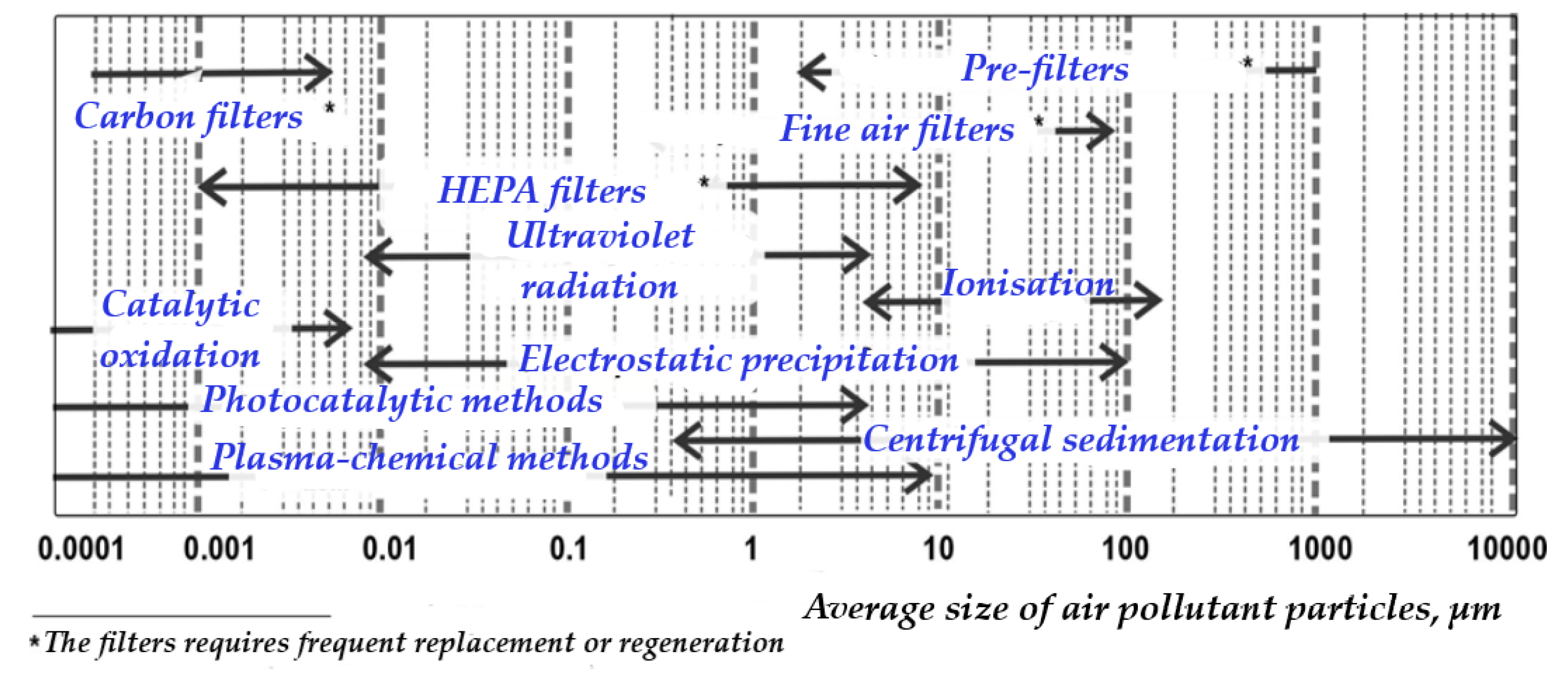
Figure 3.
Key components of the pilot-experimental installation.
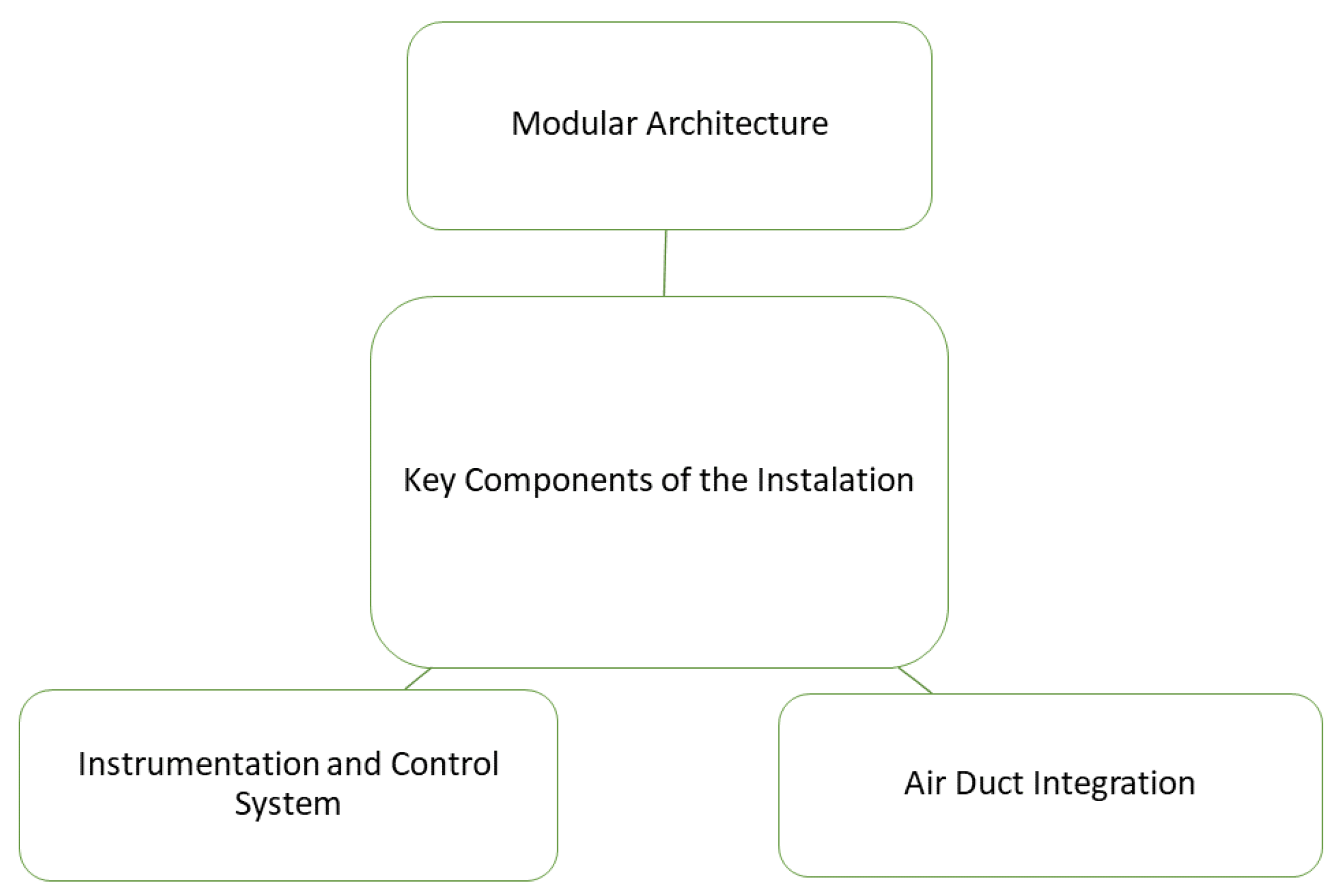
Figure 4.
Schematic diagram and modular components of the experimental installation to investigate complex air purification and disinfection processes in ventilation systems: A – coarse filter; B – plasma ioniser; C – high-voltage power supply; D – heat pump condenser; E – heat pump; F – recuperative heat exchanger; G – photocatalytic module; H – output filter; I - adsorption catalytic module; J – heat pump evaporator; K – exhaust fan with performance control; MZ1... MZ5 - air microflora monitoring zones.
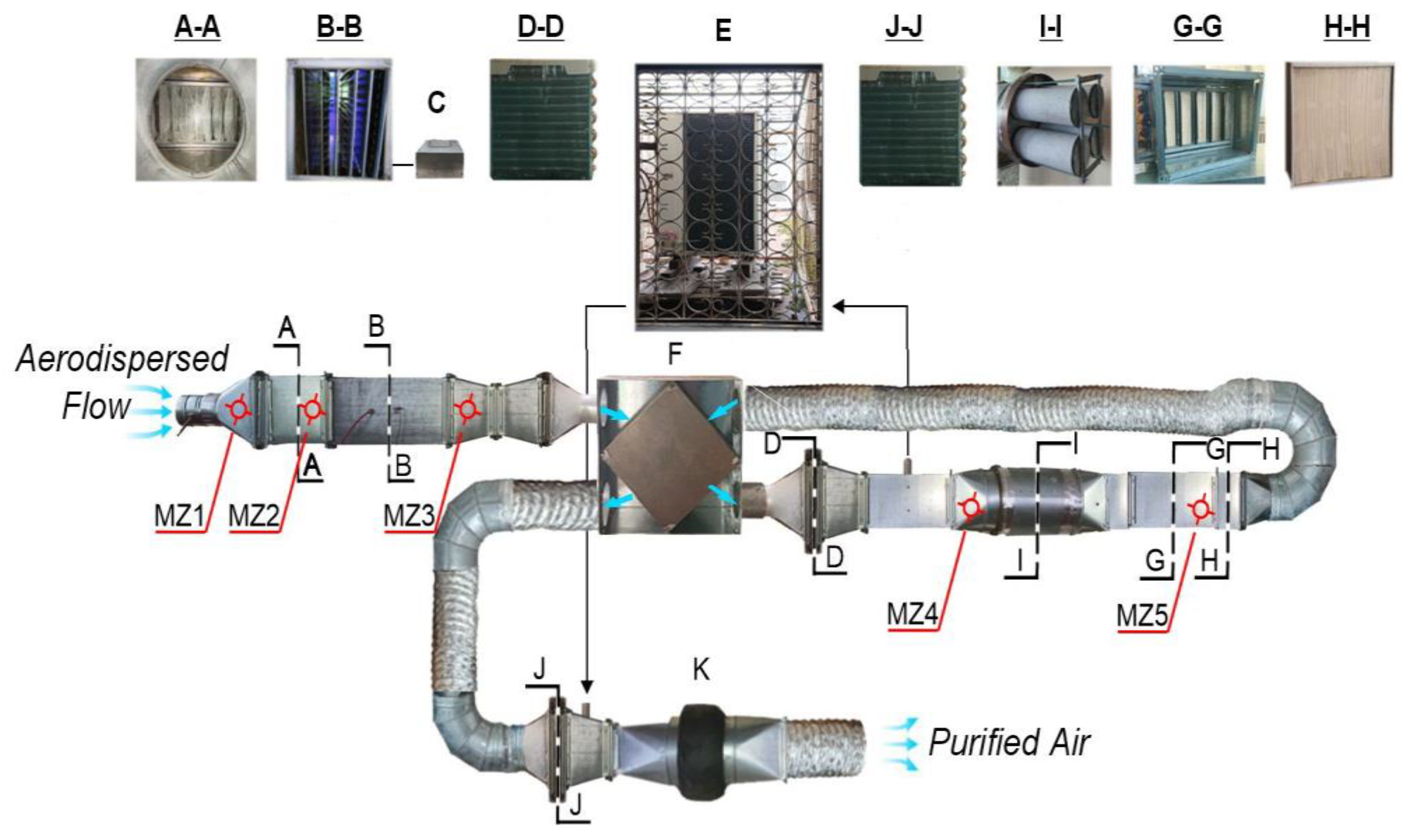
Figure 5.
Experimental determination of stable operating parameters for low temperature plasma generation: (a) Generator voltage-current characteristics (VAC) at variable L; (b) Ozone synthesis (post-generator at MZ3) as a function of applied voltage at an air velocity of 1.2 m/s and a temperature of 18–20 °C; A – air gap breakdown points; L – interelectrode distance (arc gap width).
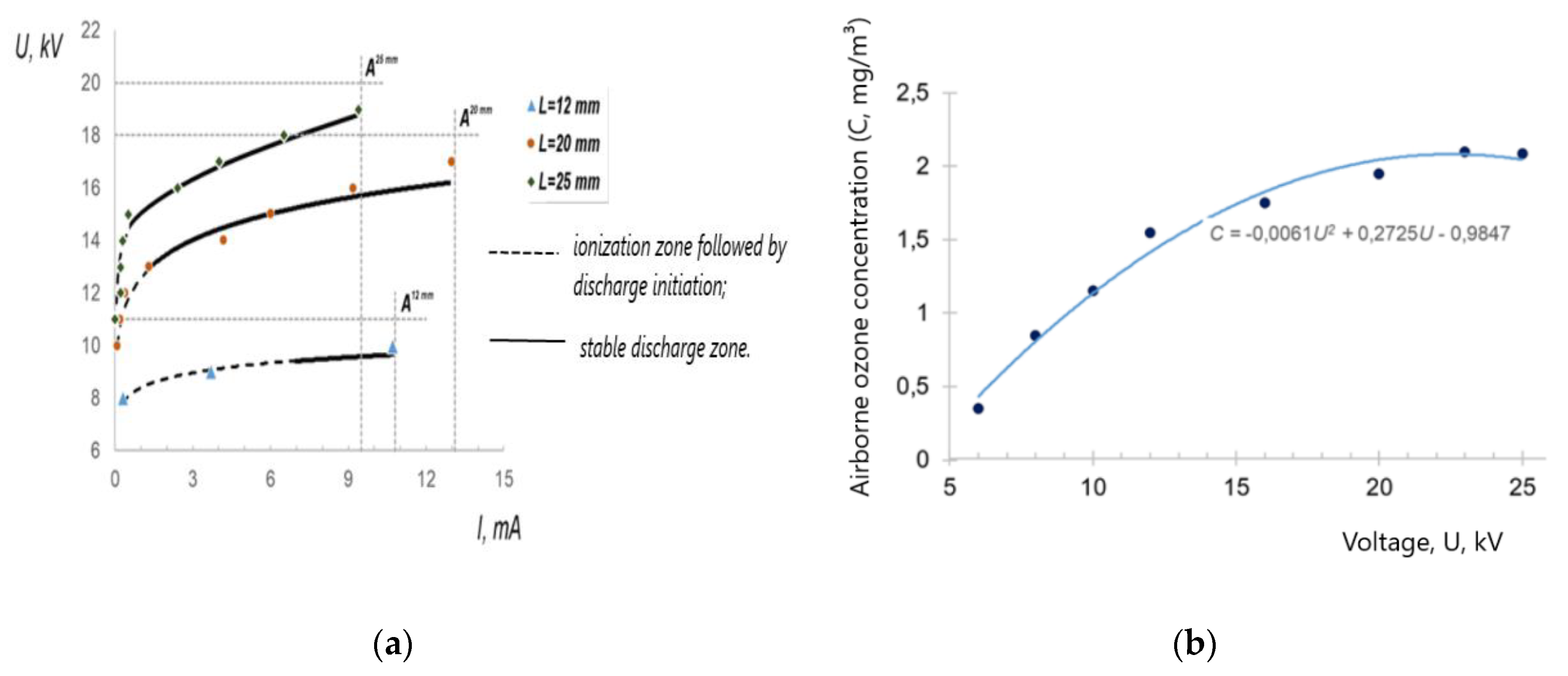
Figure 6.
Scanning electron microscopy (SEM) images of the adsorbent-catalytic granule: overview at 50x magnification (left) and detailed surface morphology at 5000x magnification (right), M, magnified structure.
Figure 6.
Scanning electron microscopy (SEM) images of the adsorbent-catalytic granule: overview at 50x magnification (left) and detailed surface morphology at 5000x magnification (right), M, magnified structure.
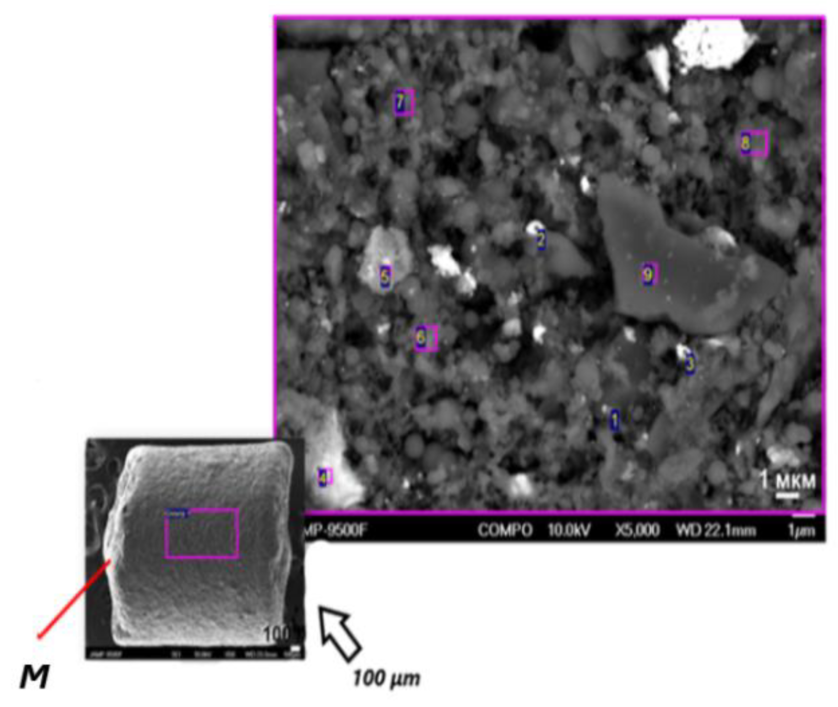
Figure 7.
Scanning electron microscopy (SEM) image of the unmodified polymer matrix carrier fibres.

Figure 8.
Cross-sectional SEM topography of the TiO2 matrix coating, illustrating surface features at (a) 270x, (b) 450x and (c) 30000x magnifications.
Figure 8.
Cross-sectional SEM topography of the TiO2 matrix coating, illustrating surface features at (a) 270x, (b) 450x and (c) 30000x magnifications.
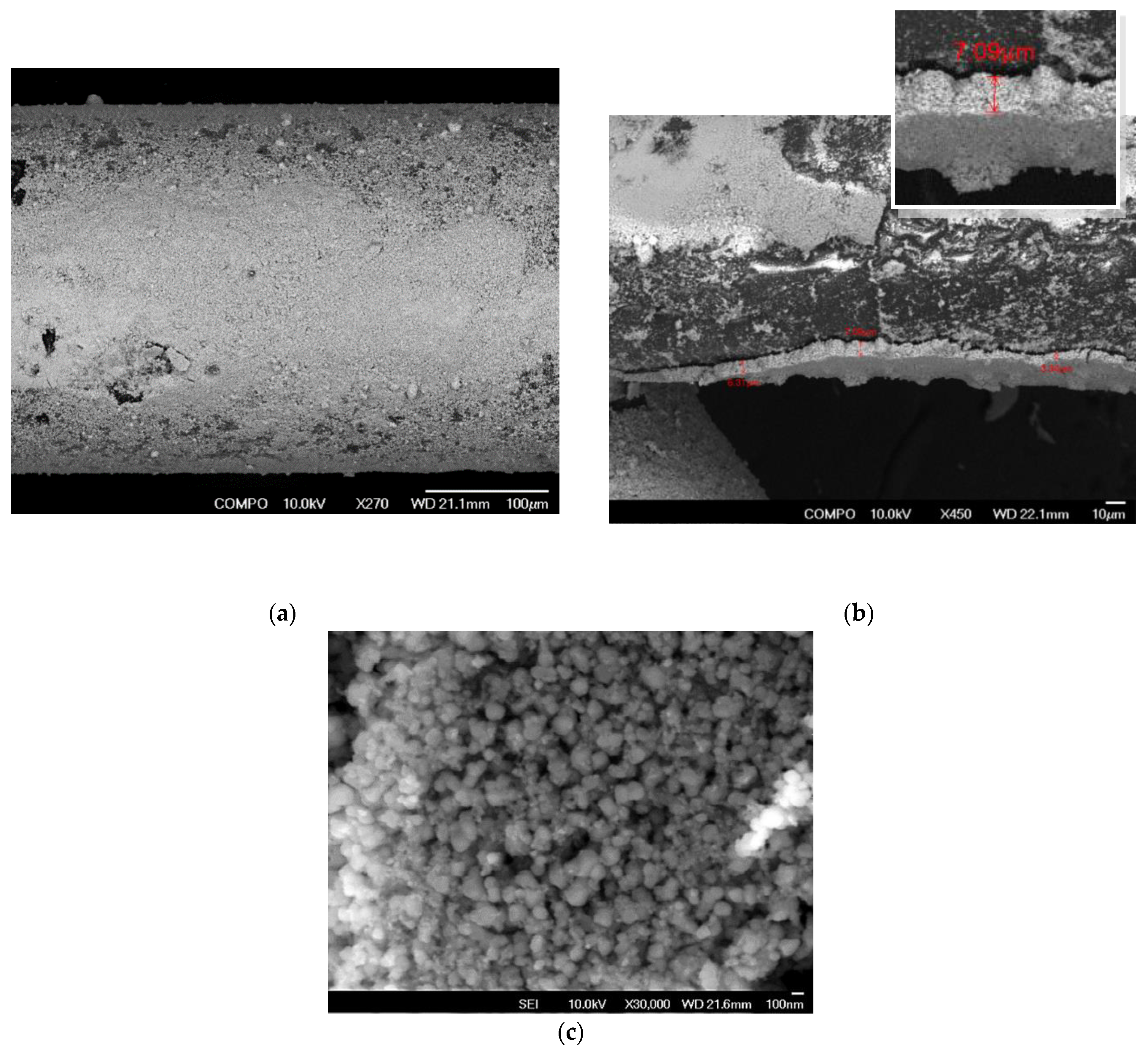
Figure 9.
Aerodynamic characteristics of the photocatalytic air disinfection module.
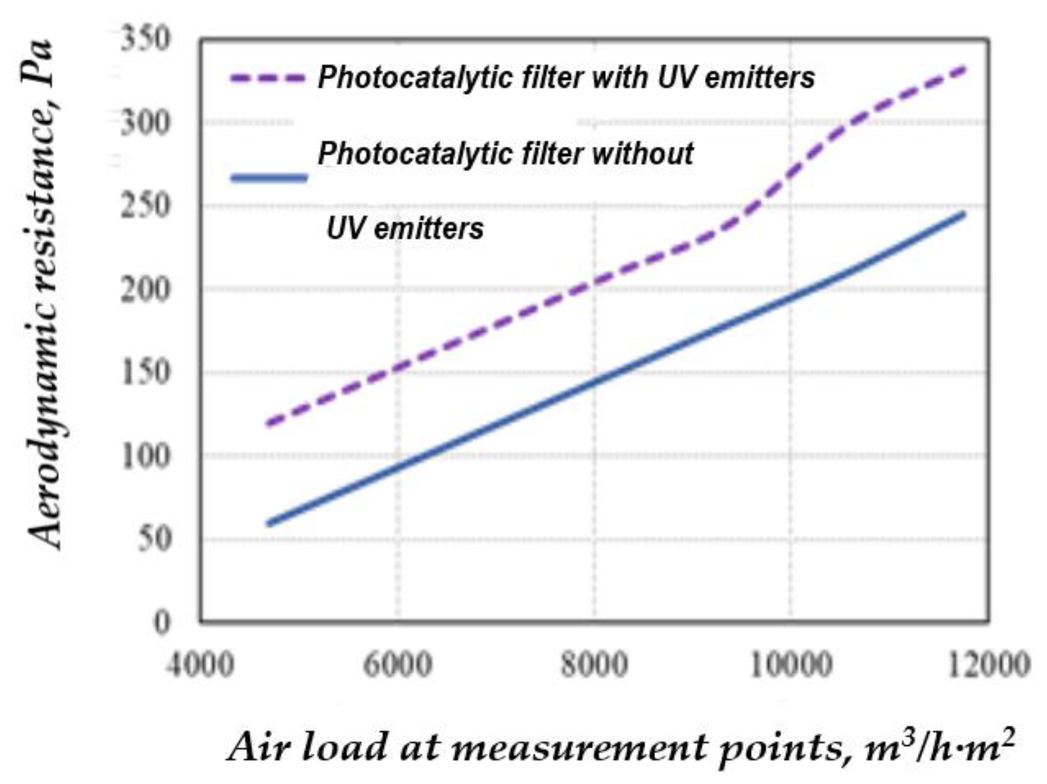
Figure 10.
Viable mould fungus colonies observed in culture medium after sampling at locations detailed in Figure 4.
Figure 10.
Viable mould fungus colonies observed in culture medium after sampling at locations detailed in Figure 4.
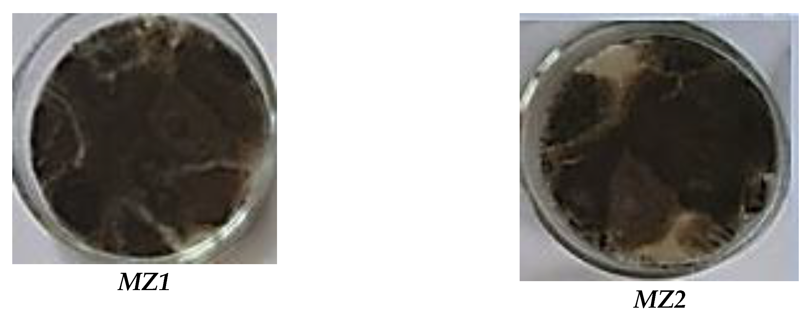
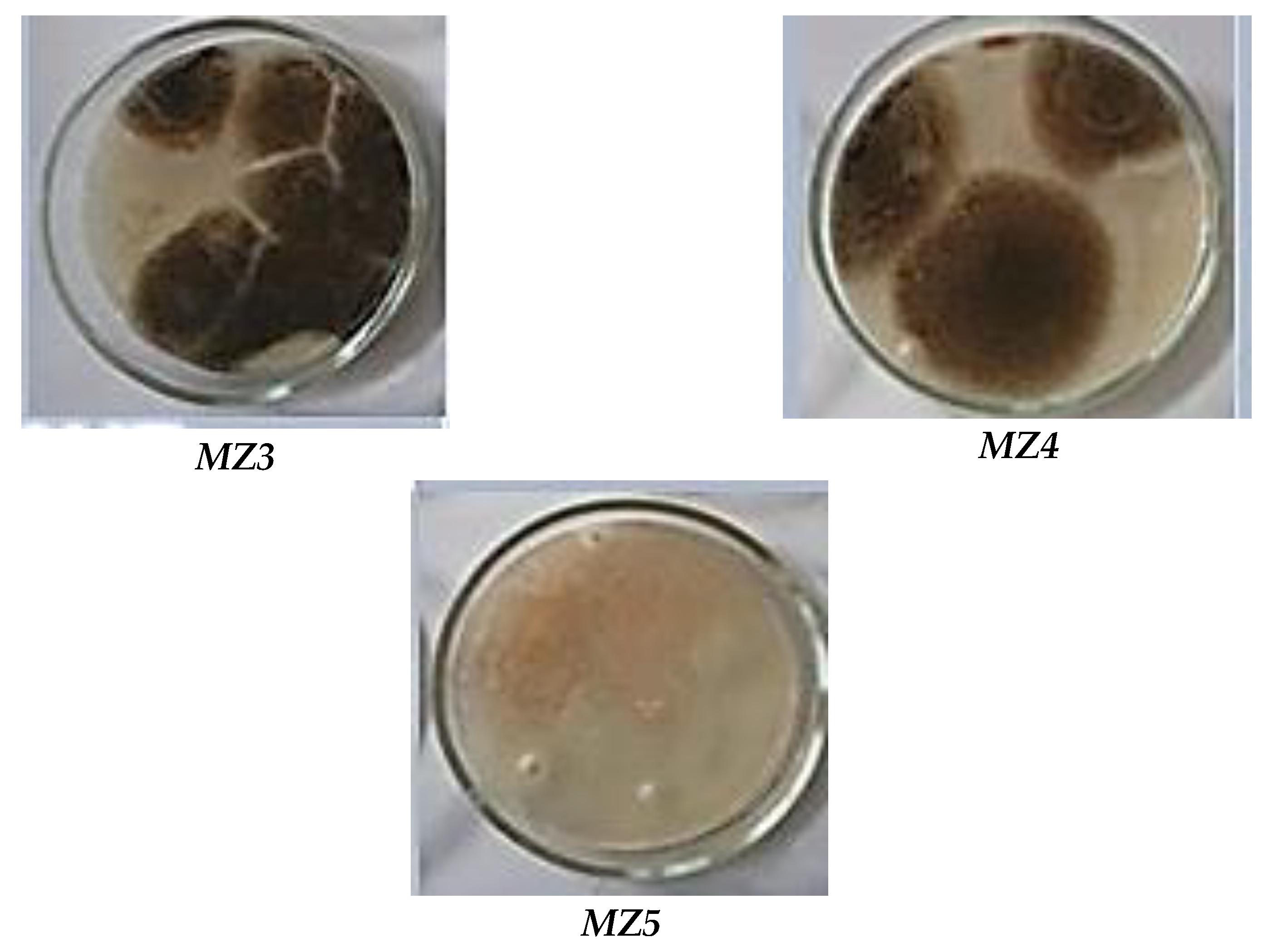
Figure 11.
Block diagram of energy-efficient air purification and disinfection: 1 - blower fan; 2 - coarse filter; 3 - bipolar plasma ioniser; 4 - heat exchanger (recuperator); 5 - heat pump evaporator ; 6 - adsorption-catalytic module, 7 - heat pump condenser.
Figure 11.
Block diagram of energy-efficient air purification and disinfection: 1 - blower fan; 2 - coarse filter; 3 - bipolar plasma ioniser; 4 - heat exchanger (recuperator); 5 - heat pump evaporator ; 6 - adsorption-catalytic module, 7 - heat pump condenser.
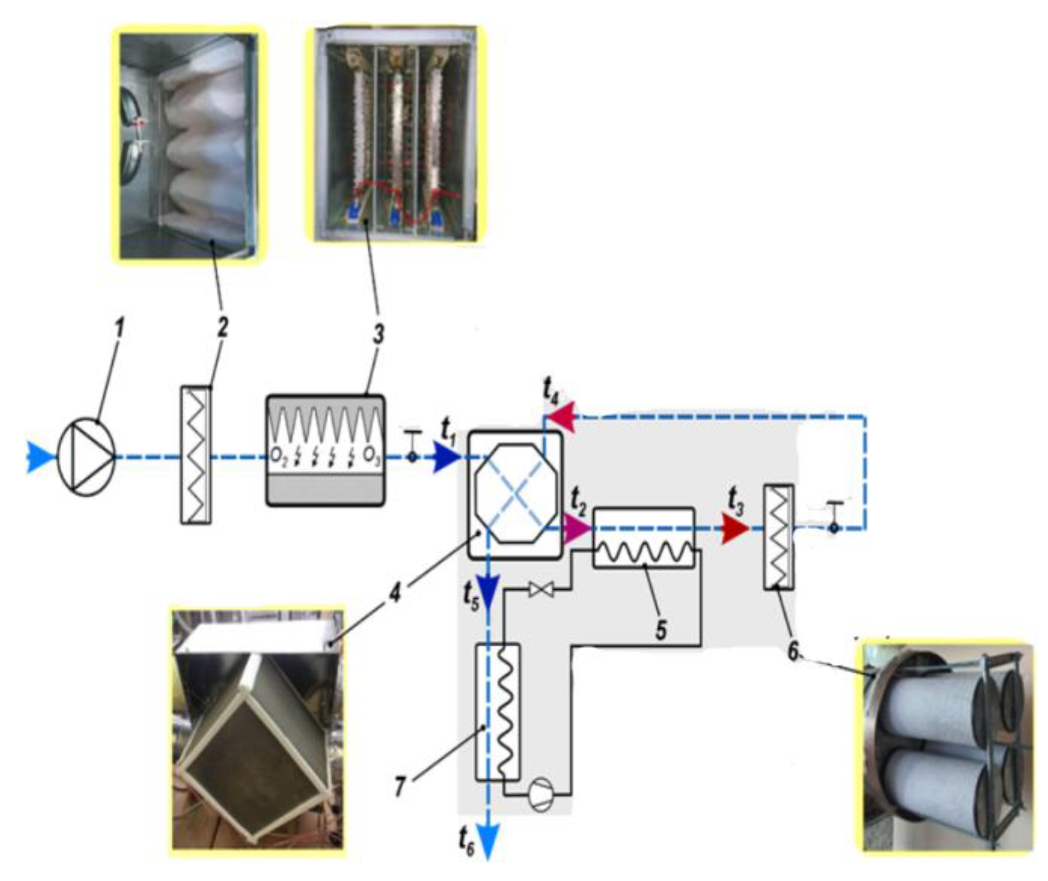
Figure 12.
Samples of indoor air microflora: (a) initial (before starting the plant); (b) after 6 hours of plant operation; (c) after 9 hours; (d) after 10 hours; (e) after 18 hours; (f) after 28 hours of module operation of the plant.
Figure 12.
Samples of indoor air microflora: (a) initial (before starting the plant); (b) after 6 hours of plant operation; (c) after 9 hours; (d) after 10 hours; (e) after 18 hours; (f) after 28 hours of module operation of the plant.

Figure 13.
Design of the low-temperature plasma generation module: (a) Stable low-temperature plasma discharge in a single section; (b) Sectional arrangement of corona electrodes and counterpolarity plates within the low-temperature plasma generation unit; 1 – saw-toothed corona electrodes; 2 – plate electrodes; 3 – corona discharge glow; L - interelectrode distance (arc gap width.
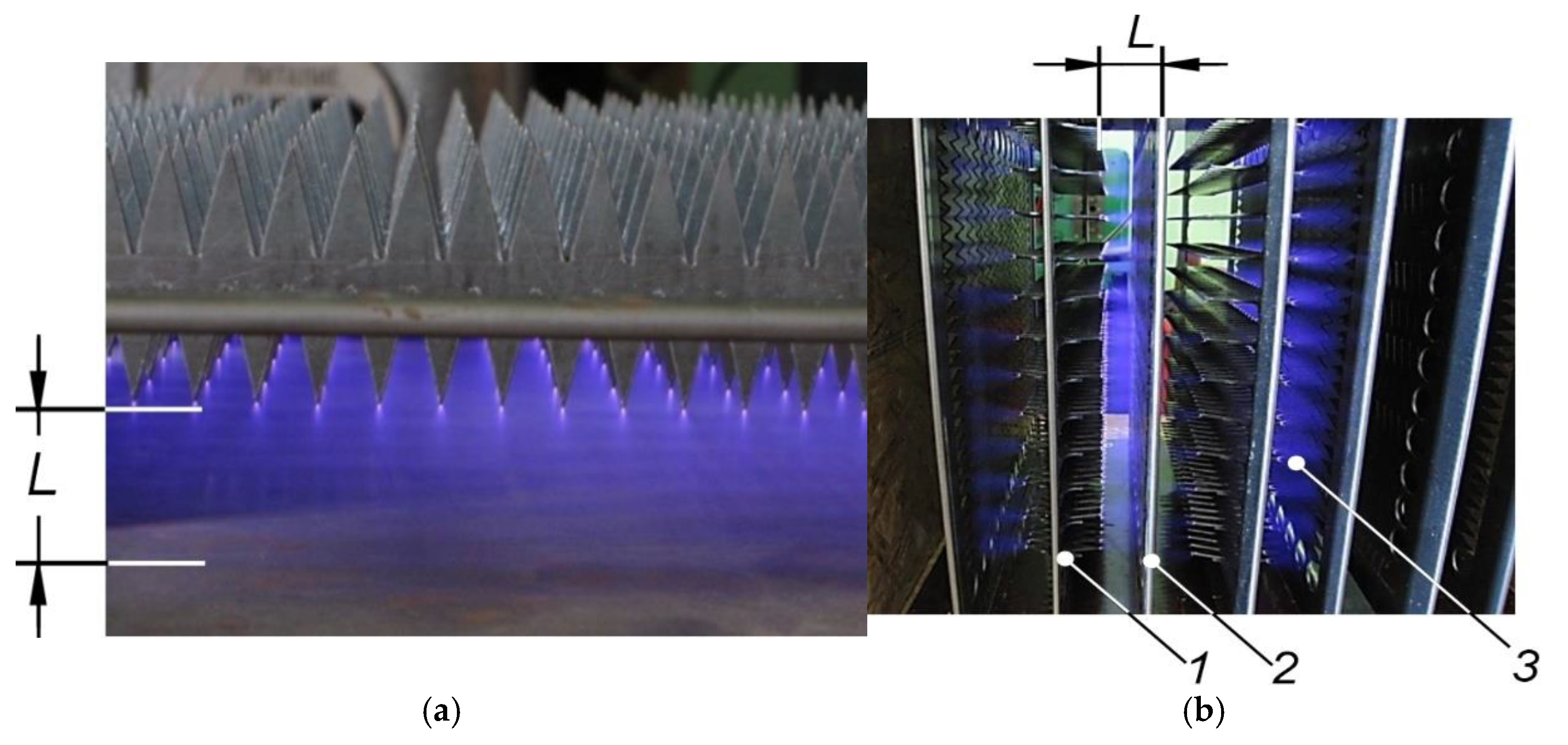
Figure 14.
Adsorption-catalytic module: 1 – cartridge, 2 – filter layers, 3 – adsorption-catalytic granular layer.
Figure 14.
Adsorption-catalytic module: 1 – cartridge, 2 – filter layers, 3 – adsorption-catalytic granular layer.
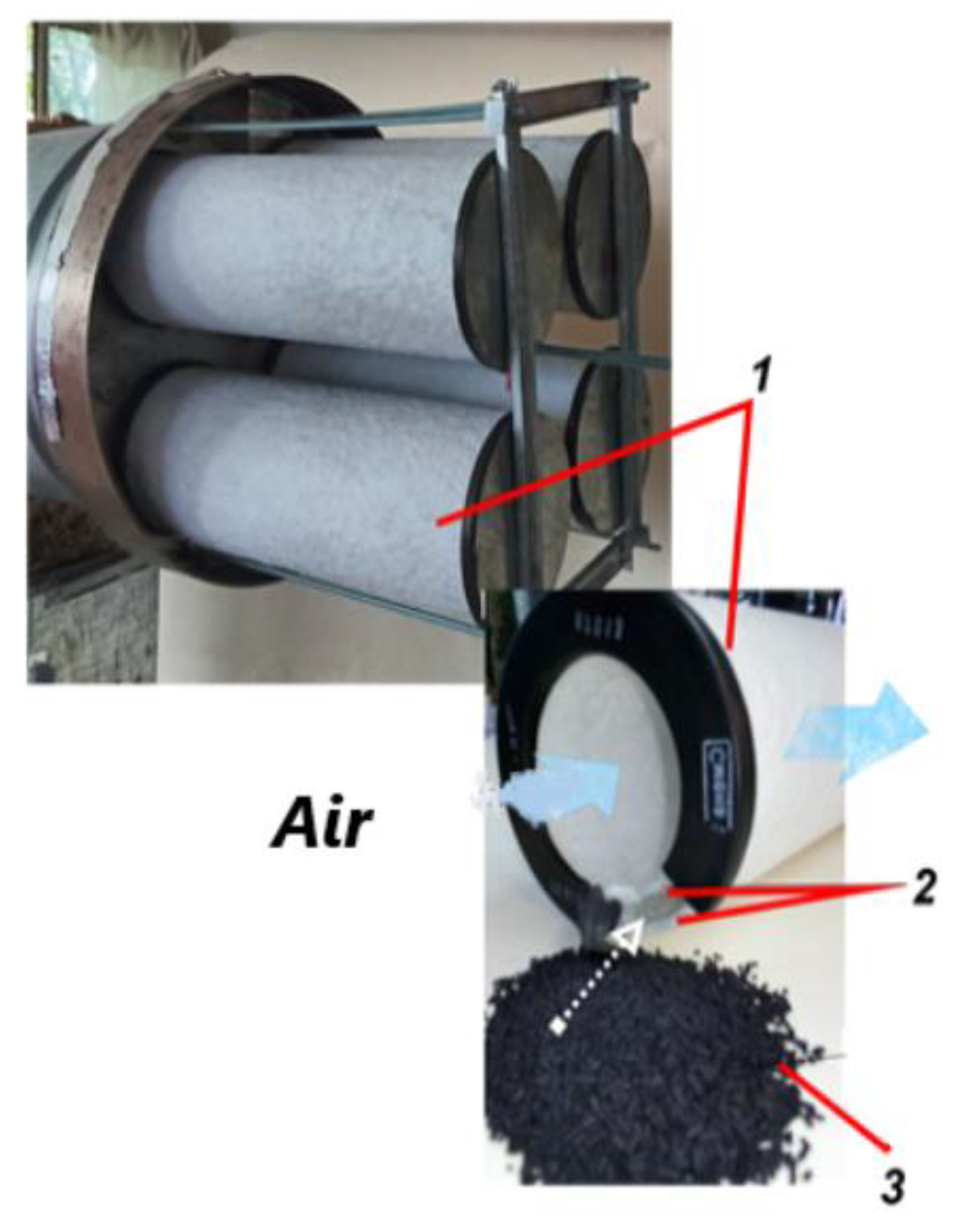
Figure 15.
Photocatalytic air disinfection module: 1 - PV cassette; 2 - PV filter; 3 - UV generator; 4 - reflective screen; 5 - filter box; 6 - UV lamp control unit; 7 - mounting frame.
Figure 15.
Photocatalytic air disinfection module: 1 - PV cassette; 2 - PV filter; 3 - UV generator; 4 - reflective screen; 5 - filter box; 6 - UV lamp control unit; 7 - mounting frame.
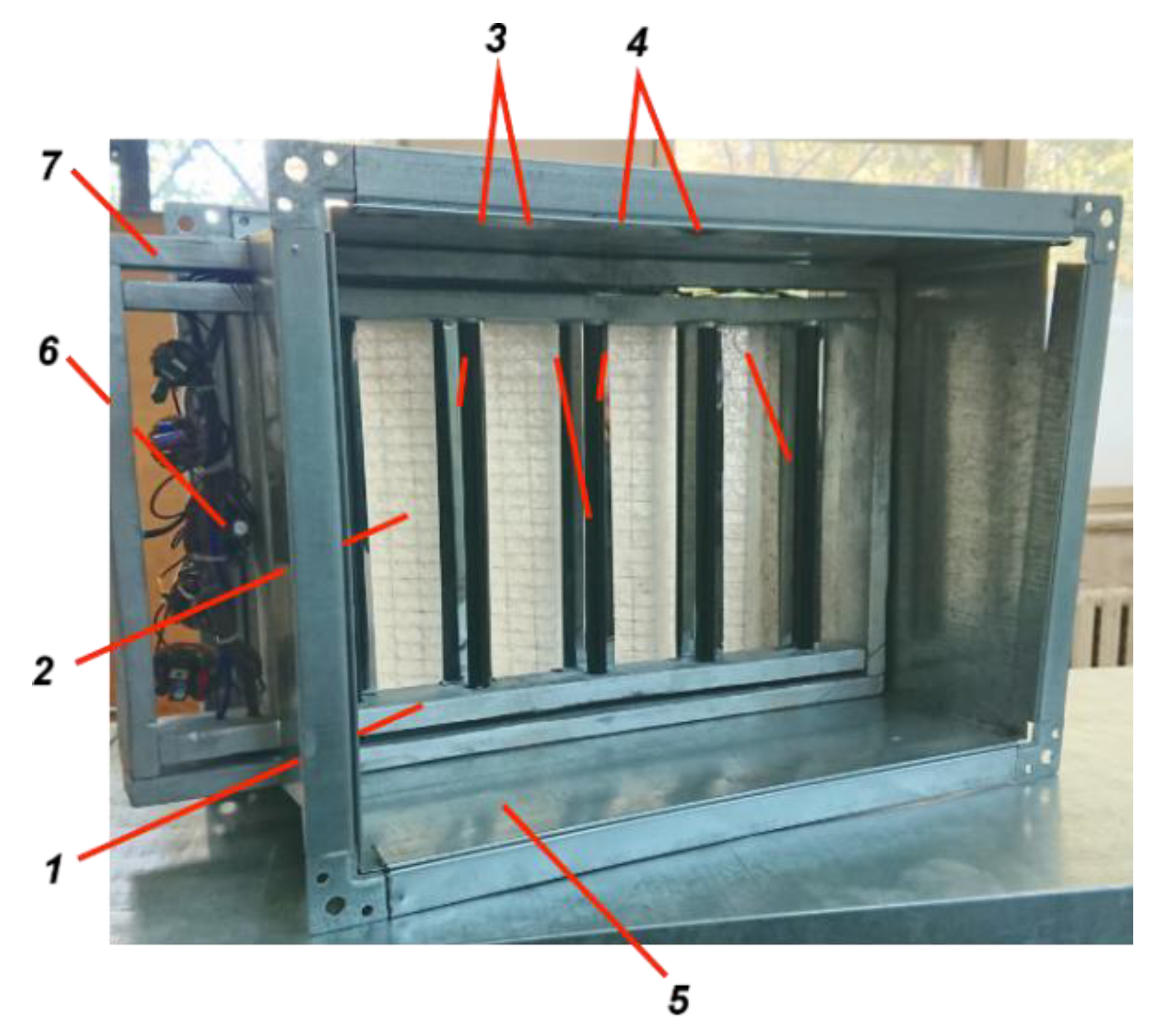
Figure 16.
Polymer cross-fin plate recuperative heat exchanger for air purification system.
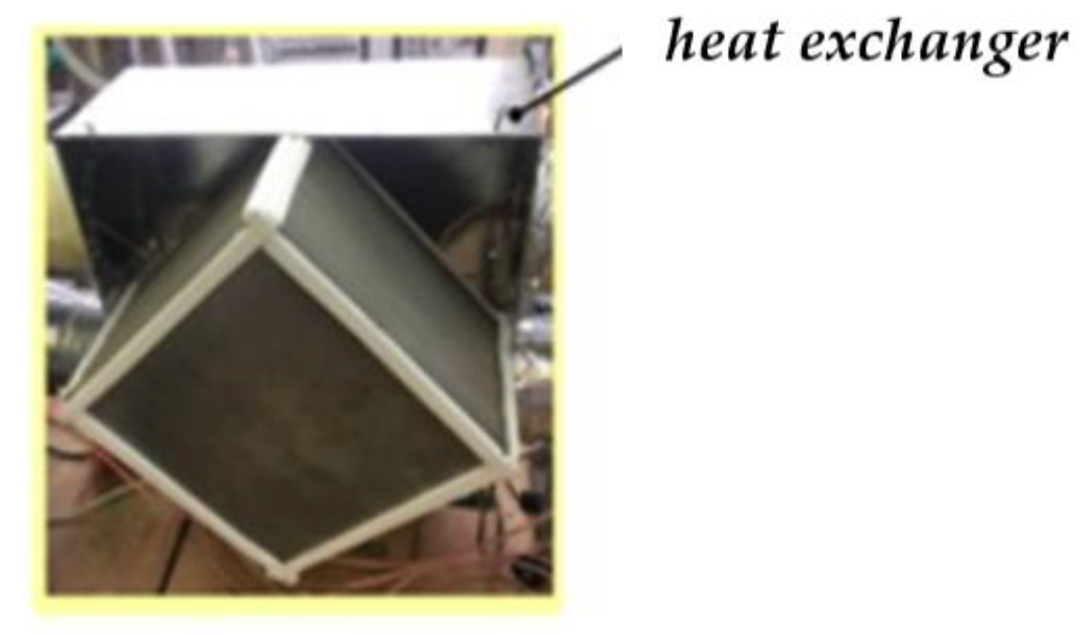

Table 1.
Elemental composition of the adsorption-catalytic granule (weight %).
| Point | C | O | Na | Mg | Al | Si | S | K | Ca | Fe |
| 1 | 74.60 | 17.21 | 0.00 | 0.02 | 2.49 | 3.16 | 0.23 | 0.00 | 2.29 | 0.00 |
| 2 | 55.12 | 13.67 | 0.06 | 1.82 | 2.27 | 10.20 | 0.04 | 0.00 | 09.02 | 7.82 |
| 3 | 66.38 | 21.32 | 0.09 | 0.22 | 3.54 | 3.93 | 0.20 | 0.14 | 02.03 | 2.14 |
| 4 | 39.80 | 33.75 | 0.99 | 0.43 | 11.01 | 10.74 | 0.06 | 0.50 | 1.16 | 1.56 |
| 5 | 78.80 | 12.59 | 0.00 | 0.95 | 0.54 | 1.10 | 2.63 | 0.00 | 0.71 | 2.68 |
| 6 | 94.63 | 3.78 | 0.00 | 0.03 | 0.39 | 0.47 | 0.38 | 0.02 | 0.24 | 0.07 |
| 7 | 97.29 | 1.99 | 0.08 | 0.00 | 0.14 | 0.08 | 0.27 | 0.00 | 0.16 | 0.00 |
| 8 | 95.53 | 2.86 | 0.03 | 0.08 | 0.39 | 0.56 | 0.45 | 0.03 | 0.06 | 0.00 |
| 9 | 96.58 | 2.84 | 0.00 | 0.01 | 0.00 | 0.07 | 0.42 | 0.07 | 0.00 | 0.00 |
Table 2.
Characteristics of the MZ aerodisperse system at the monitoring point.
| Parameters | Monitoring Points | ||||
| duration of operation of the purification: 30 min. | MZ1 | MZ2 | MZ3 | MZ4 | MZ3 |
| content of dispersed particles smaller than 2.5 µm, µg/m3 | 30.0 | 15.0 | 13.0 | 9.0 | 8.0 |
| ozone concentration, mg/m3 | 0.000 | 0.153 | 4.6 | 0.342 | 0.095 |
| relative humidity, % | 58.0 | 58.0 | 58.0 | 57.0 | 56.0 |
Disclaimer/Publisher’s Note: The statements, opinions and data contained in all publications are solely those of the individual author(s) and contributor(s) and not of MDPI and/or the editor(s). MDPI and/or the editor(s) disclaim responsibility for any injury to people or property resulting from any ideas, methods, instructions or products referred to in the content. |
© 2025 by the authors. Licensee MDPI, Basel, Switzerland. This article is an open access article distributed under the terms and conditions of the Creative Commons Attribution (CC BY) license (http://creativecommons.org/licenses/by/4.0/).
Copyright: This open access article is published under a Creative Commons CC BY 4.0 license, which permit the free download, distribution, and reuse, provided that the author and preprint are cited in any reuse.


