
Submitted:
10 March 2025
Posted:
12 March 2025
You are already at the latest version
Abstract
Autonomous Vehicles (AVs) are revolutionizing transportation by integrating advanced sensors, artificial intelligence, and communication networks to enhance safety and efficiency. This review explores the architecture of AVs, focusing on perception, localization, path planning, and control. A detailed analysis of AV sensors, including LiDAR, radar, cameras, and inertial navigation systems, highlights their roles, advantages, and limitations. Additionally, the paper examines in-vehicle and inter-vehicle communication networks, such as CAN, LIN, FlexRay, and Ethernet, which facilitate real-time data exchange. The study also addresses the key challenges AVs face, including cybersecurity threats, data processing, legal policies, and ethical concerns. By synthesizing recent advancements and ongoing challenges, this paper provides a comprehensive understanding of the state of AV technologies and their future prospects.
Keywords:
Autonomous Vehicles
; ADAS
; Sensor Fusion
; LiDAR
; Radar
; Vehicle-to-Vehicle Communication
; In-Vehicle Networks
; Cybersecurity
; Path Planning
; Artificial Intelligence
; Smart Transportation
1. Introduction
Advanced Driver Assistance Systems (ADAS) are becoming more common in both research and commercial vehicles, which is a big step toward AVs. These technologies are meant to cut down on accidents and their severity, make it easier for disabled and older people to move around, lower pollution, and make better use of infrastructure . According to a review by the National Highway Traffic Safety Administration (NHTSA) , human related errors like distraction, fatigue, and emotional driving cause are about 94% of accidents. One of the main reasons for the fast development of AV technologies is that they don't have these problems [1].
As the world's research, testing, and use of AVs grows, the creation of standardized rules and guidelines has become very important to make sure their safe integration into society. Recently, the U.S.Department of Transportation and the NHTSA have agreed to follow the international standard for automation levels set by the SAE, which has classified automated vehicles into six levels [2]. Level 0 represents vehicles where the driver has complete control, while Level 5 signifies vehicles that have complete control over all driving functions. The depicted levels can be observed in Figure 1 At present, levels 2 and 3 are indeed being implemented in certain commercial vehicles, including Tesla's Autopilot [3], GM's Cruise [4], and BMW [5]. Autonomous cars incorporate advanced features such as automatic braking, adaptive cruise control, and lane keeping assist systems.
Currently, automotive companies such as Volkswagen's Audi and Tesla are incorporating Level 2 automation as per SAE standards in their vehicle automation systems, as seen with Tesla’s Autopilot and Audi A8’s Traffic Jam Pilot. Alphabet’s Waymo has been exploring a business strategy since 2016 that involves Level 4 autonomous driving technology to run self-operated taxi services in certain regions of Arizona, USA [6].
While there may be slight variations among different vehicle systems, they all must address the issue of autonomous navigation, which can be broadly categorized into four key components: perception, localization and mapping, path planning, and control. Perception involves the utilization of a set of sensors installed on the vehicle to detect, understand, and interpret the surrounding environment. This includes identifying both stationary and moving obstacles, such as other vehicles, pedestrians, traffic signals, road signs, and curbs. The goal of localization and mapping tasks is to accurately determine the vehicle's global position in relation to world coordinates. In addition, it is responsible for creating a comprehensive representation of the vehicle's environment and consistently monitoring the vehicle's position [4].
Path planning utilizes the results of the preceding two tasks to determine the most advantageous and secure route for the AV to reach its destination, taking into account all potential road obstacles [7]. Finally, the control element produces the required values of acceleration, torque, and steering angle for the vehicle to track the chosen path [8]. In addition, several studies examine the incorporation of connected vehicle technologies [9,10], such as vehicle-to-vehicle (V2V) and vehicle-to-infrastructure (V2I) technologies. These technologies enable the sharing of crucial information to establish an improved cooperative driving environment, as depicted in Figure 2 This enhanced and refined collaborative perception enables vehicles to efficiently forecast the actions of crucial environmental elements (such as obstacles, roads, ego-vehicles, environment, and driver behavior) and proactively anticipate any potentially dangerous occurrences.
The selection and arrangement of sensors is crucial in AV systems to replicate human perception and understanding of the environment. The performance of these sensors is often enhanced by the collaboration of multiple sensors operating on different wavebands, resulting in a fused output. Sensor fusion is an essential procedure in overcoming individual sensor constraints and enhancing the overall effectiveness of the AV system. Efforts are being made to improve the efficiency, dependability, durability, and precision of self-driving vehicle components. Cybersecurity and safety concerns during driving situations are also of utmost importance [4].
AVs are utilized in various industries, including transportation, logistics and delivery, agriculture, mining and construction, military and defense, public safety and emergency response, and urban planning and infrastructure development. These vehicles offer convenient and efficient mobility solutions for commuters and travelers, while also being capable of navigating fields and performing precision agricultural tasks. They can operate in hazardous environments, improve productivity and safety on job sites, and provide reconnaissance and support in hazardous situations. In military and defense applications, AVs can perform reconnaissance, surveillance, and transportation of troops and supplies, navigating rugged terrain. In public safety and emergency response scenarios, AVs can assist first responders by providing reconnaissance and support in hazardous situations. Lastly, AVs can optimize traffic flow, reduce congestion, and improve road safety in urban planning and infrastructure development [8].
2. AV Sensors
Effective autonomous driving pivots on the vehicle's ability to accurately interpret its surroundings. This necessitates a sophisticated sensor array that can capture a full spectrum of environmental data. The integration of multiple sensors is imperative because it addresses the limitations inherent to relying on a solitary data source. For instance, while one sensor may excel in bright conditions, another might be better suited for low-visibility scenarios. By binding the collective capabilities of diverse sensors, AVs can achieve a more comprehensive understanding of their environment, which is essential for the safe execution of navigation and driving tasks [6].
Sensors are devices that can detect changes or events in their surroundings and translate that information into a numerical measurement. These devices are generally classified based on their function. A vehicle's operational status, including physical and dynamic states like motor speed, wheel position, and electrical parameters, can be tracked and transmitted by sensors that monitor internal dynamics; these sensors are called internal or proprioceptive sensors [1,11].
On the contrary, the vehicle's external sensors or called exteroceptive sensors—which include cameras, radar, LiDAR, and Inertial Navigation System (INS) —are responsible for collecting data from the surrounding environment and measuring variables like distance and intensity. For vehicles to detect obstacles, plan routes, and carry out drills safely, these sensors are essential. They will eventually be completely integrated with the vehicle's control systems, which will make driving safer and more efficient [1,6,11].
Developed in the 1960s, Light Detection And Ranging (LiDAR) technology has since found extensive use in aircraft and space exploration terrain mapping. Manufacturers of laser scanners began using commercially available LiDAR systems with a pulse rate of 2000-25,000 Pulses Per Second (PPS) for topographic mapping in the mid-1990s [12]. Today's LiDAR sensors are capable of measuring distances at rates greater than 150,000 PPS [13]. LiDAR is a method of remote sensing that detects objects by reflecting pulses of infrared or laser light off of them. By tracking the amount of time, it takes for a pulse of light to travel from its point of emission to its point of reception, the device is able to detect reflections and determine distance. In one, two, or three dimensions, LiDAR sensors record data as a collection of points, or PCD, and they also record object densities. The PCD includes the x, y, and z coordinates, along with the intensity data, of the obstacles present in the 3D LiDAR sensor's Field of View (FOV).
RADAR, also known as Radio Detection and Ranging, was developed prior to World War II. The concept involved the emission of electromagnetic (EM) waves in a specific area and the reception of scattered waves (or reflections) from targets. These waves are then processed to obtain range information. The Doppler property of electromagnetic waves [14] is utilized to determine the relative speed and position of identified obstacles. The Doppler effect, or Doppler shift, refers to the phenomenon where the frequency of a wave changes due to the relative motion between the wave source and its targets. As the target moves towards the direction of the radar system, the frequency of the detected signal increases, resulting in shorter waves [15].
Depending on their operational mode, sensors can be passive, merely receiving environmental inputs, or active, emitting signals and analyzing the returned energy to infer information about their surroundings. AVs rely on an array of such sensors for comprehensive environmental perception and for making informed navigational decisions, essential precursors to actuating vehicle movement [1,6].
The selection of a suitable sensor is crucial for the optimal operation of a perception stage, as each has advantages and disadvantages. Automakers conduct thorough simulations to choose and implement various sensors in their vehicles to achieve advanced levels of autonomy. Cameras can perceive objects, identify road signs, and differentiate obstacles, but their effectiveness depends on lighting and weather conditions. Radars accurately measure distances and speeds in any weather but cannot differentiate between obstacles and are sensitive to noise in metallic environments. Lidar is highly accurate in distance measurement and less susceptible to noise, but it is more expensive, less visually appealing, and underperforms in adverse weather conditions. Figure 3 presents a comparative chart of these sensors, including their advantages and disadvantages [16,17].
AVs are being equipped with additional sensors components to enhance the safety of autonomous driving. The quantity of data traffic and the quantity of sensors, including cameras, lidar, and radar, needed for AVs are growing in order to facilitate more advanced levels of autonomous driving. With the growing amount of data being transmitted within vehicles, it is imperative to develop IVNs that take into account the specific communication needs of AVs. Table 1 depicts the specified deadline requirements for each sensor [18].
Sensor configurations for different vehicle categories are shown in Table 2, with each sensor serving a unique purpose in a variety of industries. Table 2 presents a methodical arrangement intended to make it easier to compare different sensor configurations. The sensors are categorized in the table based on the kind of vehicle, the industry they serve, and the level of automation they enable [19].
3. Vehicle Networks
Sensors like Camera sensors, LiDAR, and millimeter-wave Radar generate information for the perception layer, which is crucial for autonomous driving. The planning layer integrates this information with feedback from the control layer, implementing specific control instructions like following, overtaking, and accelerating [20,21].
However, these sensors have limitations such as unreliability, infeasibility, and inefficiency. Unreliability refers to the difficulty in decision-making by sensors alone. In contract, infeasibility refers to restricted perception capacities and operating conditions due to intrinsic features like fading lane lines, broken traffic lights, dense pedestrian flow, and large traffic flow. Inefficiency refers to the inability of sensors to detect traffic jams or accidents due to their limited view [22].
Networking and communication technologies can address these limitations by sharing real-time information among vehicles, reducing the demand for sensors, and using this information for accurate path planning. These technologies not only have high commercial values for entertainment applications and advertisement delivery but also provide management convenience for government sectors, such as promoting public information dissemination, broadcasting traffic management directives, and monitoring vehicle operating status [22].
AV’s networking and communication technologies can be classified into two categories: intra-vehicle and inter-vehicle. The intravehicular network (INV) serves as a basis for achieving autonomous driving by connecting the electronic components within the vehicle. Another crucial component is the inter-vehicle network, which serves as the means for vehicles to communicate and exchange information with other vehicles.[22]
The inter-vehicle network is categorized into low-power technologies such as ZigBee or Bluetooth, 802.11 family technologies, base station-driven technologies, and other auxiliary technologies. Zigbee Dedicated Short Range Communication (DSRC) and Long Term Evolution-Vehicle (LTE-V) are specifically tailored for automotive applications. Emerging communication technologies, such as 5G, computing technologies, Simultaneous Wireless Information and Power Transfer (SWIPT), Visible Light Communication (VLC), and deep learning, offer new opportunities for networking and communications in autonomous driving [22].
In contrast, an IVN network facilitates the communication of status data and control signals among an AV's sensors, actuators, and ECUs. These technologies establish a scalable backbone infrastructure, which is integral for implementing sophisticated functions like sensory perception, motion control, and system fault diagnostics in a unified central system [23]. AVs currently employ a range of data bus technologies, including Ethernet, Local Interconnect Network (LIN), FlexRay, Media Oriented System Transport (MOST), and CAN, which will be comprehensively discussed in chapter three.
A. Local Interconnect Network (LIN)
In applications like window control, mirrors, seat adjustments, and other non-safety-critical functions, the extensive protection and high cost associated with CAN technology were deemed excessive. This realization prompted the formation of the LIN Consortium in the late 1990s, comprising companies like Volkswagen, BMW, Volvo, and Daimler. Their collaborative effort led to the inception of LIN, with its initial version launched in November 2002 [24].
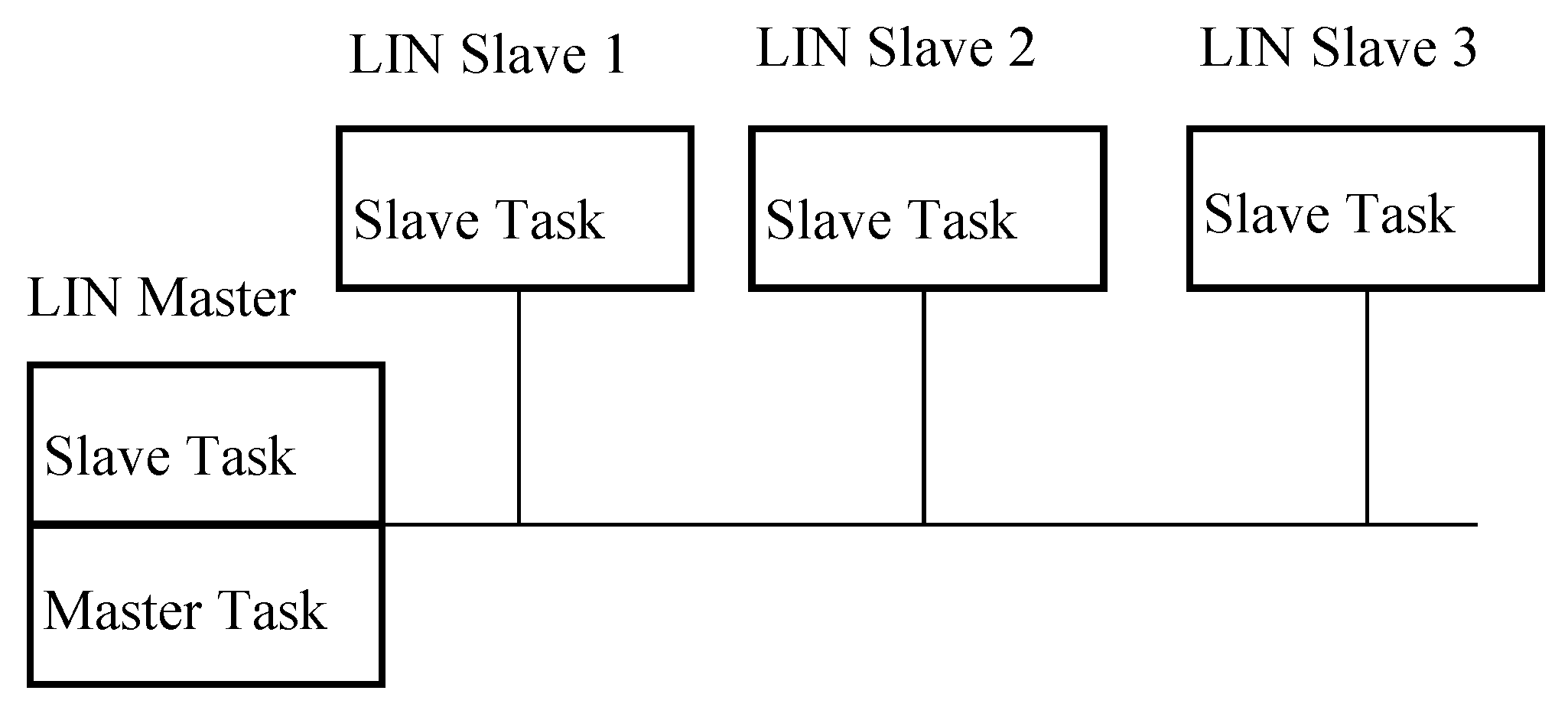
The LIN technology was engineered with a focus on simplicity, employing a 1-wire unshielded setup with a restricted data rate of 20 Kbps, typically operating at 12V and utilizing binary symbols - dominant 0 and recessive 1 [24]. The architecture involves a straightforward Master/Slave bus system, wherein a single LIN Master communicates with multiple LIN Slaves, as depicted in Figure 4. Notably, the Slave ECUs can transmit data only upon receiving a query from the Master ECU, initiated by a specific header.
Scheduling within LIN is predefined during the design phase via a schedule table, outlining the frame list to be transmitted and their corresponding scheduled time periods. Each frame transmission occurs within an allocated time period known as the Frame Slot [24]. As illustrated in Figure 5, the LIN frame comprises several essential fields that govern its structure and transmission.
- Break: This field lets all nodes know that a message is being sent. As a token, it is always sent by the master;
- SYNC: the field for synchronization. As a token, it is always sent by the master;
Figure 4.
LIN bus Topology [24].
Figure 4.
LIN bus Topology [24].
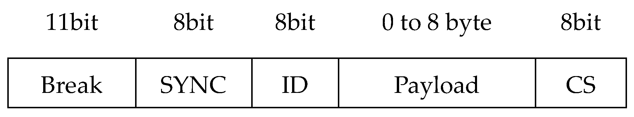
Figure 5.
LIN frame [24].
Figure 5.
LIN frame [24].
- ID: a way to identify a message. The ID can only be between 1 and 64. As a token, it is always sent by the master;
- Payload: a field of data. It can be sent by either the master or the slave;
- Checksum: 8 bits to find mistakes. It can be sent by either the master or the slave.
B. Media Oriented System Transport (MOST)
During the 2000s, the surge in advanced automotive features such as navigation systems, intricate audio setups, Bluetooth integration, and sophisticated displays led to a noticeable surge in data traffic. In response, companies like BMW, Harman/Becker, and SMSC joined hands to establish the MOST Cooperation, pioneering the MOST technology [27].
The MOST was specifically engineered to streamline the transportation of audio-video data, addressing the limitations of CAN and LIN networks that couldn't ensure high bandwidth for such purposes. Notably, the latest iteration, MOST150, boasts an impressive 150 Mbps speed, accommodating Ethernet Packet Channel with Internet Protocol (IP) functionalities.
Operating across all OSI model layers, MOST typically leverages Plastic Optical Fiber (POF) cable as its physical layer to circumvent electromagnetic interference issues and ensure electrical isolation. However, the versatile MOST150 also supports coaxial cable. Despite their bandwidth advantages, both physical layers are considered costly, contributing to the declining popularity of MOST technology.
The technology operates synchronously using Time Division Multiple Access (TDMA), ensuring uniform clocking across all nodes to prevent collisions. Employing a ring topology illustrated in Figure 6, MOST designates one ECU as the timing master, facilitating synchronization across all nodes via synchronization messages. Starting with the master ECU initiating unidirectional communication with the next node, each successive node passes the frame until it reaches the intended recipient [27]. Figure 7 shows the MOST150 frame format, which consists of four main fields and has a size of 384 bytes:
- Control Channel: utilized to control network operations;
- SYNC Channel: utilized for synchronous audio-video exchange (digital and analog audio-video);
- ASYNC Channel: utilized for asynchronous package transmission. (Traffic on the Internet and data obtained from the navigation system);
- MOST Ethernet Packets: initially introduced for IP data in MOST150.
C. FlexRay
During the 2000s, a consortium comprising major entities like BMW, Bosch, Daimler, and several others collaborated on the development of the FlexRay protocol. Their primary objective was to engineer a time-triggered communication standard catering to safety-critical and time-sensitive automotive applications, encompassing various X-by-Wire systems such as brake-by-wire and steer-by-wire, along with powertrain and chassis controls. Despite the numerous advantages and drawbacks inherent in FlexRay, several companies have either discontinued its usage or are in the process of doing so. [25,26].
FlexRay technology operates on cycles, employing two distinct window types: time-triggered (static) and event-triggered (dynamic). The former relies on a TDMA protocol, organizing numerous identical slots across time. In instances where a node doesn't necessitate transmission, a null frame is sent to ensure continual reception of signals [27]. Conversely, the latter leverages Flexible Time Division Multiple Access (FTDMA), dividing time into sub-slots, allowing each station to initiate communication within its designated sub-slot.
This network exhibits significant flexibility in its topology, accommodating various configurations including linear bus, active and passive stars, and point-to-point setups, as depicted in Figure 8 and Figure 9. Moreover, redundancy can be integrated into the topology via dual channels [24,27].
The FlexRay frame format, depicted in Figure 10, comprises three fundamental sections: header, payload, and footer. The header section encompasses:
- Status Bit: indicates the start of the frame, which can indicate a startup, sync, or null frame;
- Frame Identifier (ID) : the frame's unique identity;
- Length: the data section's length;
- Header CRC: header section error checking;
- Cycle: the cycle's number.
D. Standard Ethernet
Ethernet, considered the most extensively employed Local Area Network (LAN) globally, was originally conceptualized by Xerox PARC in the early 1970s. Initially designed to establish a connection between computers, the internet, and printers, Xerox released this technology for universal adoption. Subsequently, in 1983, the IEEE launched the 802.3 Project within its domain, embarking on continual expansions and enhancements of Ethernet standards. The IEEE 802 project structure delineates three distinct layers [27]:
1. Physical Layer (PL):
- (1)
- 10 Mbps Ethernet: employs the Carrier Sense Multiple Access with Collision Detection (CSMA/CD) protocol.
- (2)
- Fast Ethernet: an evolution from its predecessor, featuring full-duplex transfer and a star center (switch) configuration, ensuring each received frame is solely retransmitted to the intended recipient line, not broadcasted.
- (3)
- Gigabit Ethernet: an advancement of Fast Ethernet with the capability for half-duplex transmissions using a hub or full duplex with a switch.
- (4)
- 10 Gigabit Ethernet: exclusively full duplex.
Ethernet networks follow various XBaseY specifications, contingent on factors such as bandwidth (X), network segment length, and transmission medium (Y). For instance, 10-Base-T denotes a 10 Mbps network operating on unshielded twisted pair (UTP) [27].
2. Medium Access Control (MAC): oversees node access to the network, manages packet losses, and addresses collision handling.
3. Logical Link Control (LLC): functions as an intermediary between the MAC protocol (lower layer) and the upper layer (network), abstracting the type of MAC protocol in use [28].
As per the IEEE 802.3 standard, the Ethernet frame structure, detailed in Figure 11, comprises distinct fields including:
- Preamble: utilized to maintain signal synchronization between source and destination;
- Start of Frame Delimiter: the start of the frame is indicated by the 10101011 sequences;
- Destination and Source Address: specify the recipient's and the sender station's addresses, respectively.
- Length: the following field's length.
- LLC-PDU: data transmitted payload.
- Frame Check Sequence: it includes the error-checking Cyclic Redundancy Check (CRC).
The choice of networking technologies within an AV is influenced by the nature of the information, as well as cost and efficiency requirements. Table 3 presents the functional domains and the corresponding legacy IVN technologies [26] , an illustrative diagram of a hybrid IVN architecture in an AV is presented in Figure 12, the intra-vehicle networking structure of AVs is highly diverse. For instance, CAN is utilized for body control, LIN for low-bandwidth serial control messages, FlexRay for real-time security, MOST for multimedia transmission, and Ethernet for diagnosis. In autonomous vehicles, diverse communication technologies with varying rates and transmission modes create a more complex heterogeneous network than in traditional vehicles [22].
4. AV Challenges
AVs are anticipated to yield significant societal advantages, including traffic optimization and fewer accidents. AVs have been the subject of extensive research for several decades, with a particular focus in the last five years. The collaborative efforts between universities and manufacturers have resulted in the near completion of AVs. AVs are widely believed to significantly reduce transportation expenses. According to one estimation, the effects of AVs on society, including savings from reduced crashes, decreased travel time, improved fuel efficiency, and parking advantages, could amount to approximately $2000 per year per AV. When considering all costs associated with crashes, this figure could potentially reach as high as $4000 [23].
The primary obstacle to achieving dependable, seamless, and secure driving is the perception of the surroundings. A comprehensive range of research inquiries, encompassing various aspects, must be examined and resolved. These include, but are not limited to, customer acceptance, societal impacts, communication technologies, ethical concerns, planning, standards, and policy [28,29].
Issues related to system security and integrity have arisen as significant challenges in the field of software. These implications have various policy ramifications, such as the need for policymakers to efficiently manage and regulate a wide range of vehicles with distinct operational limitations. Policymakers must guarantee that drivers comprehend the capabilities of these vehicles and can operate them safely. An upcoming challenge is to establish connections between multiple intelligent vehicles and the infrastructure, leading to the implementation of big data. Big data involves the processing and analysis of extensive datasets [30,31], based on research conducted at the Australian Engineering Conference (AEC) in 2018, it was found that an AV will produce approximately 166 gigabytes of data per hour and around 4000 gigabytes of data per day [32,33,34]. AVs will soon become an essential component of contemporary transportation systems [35,36,37].
5. Analysis of Autonomous Vehicle Technologies
Autonomous Vehicles (AVs) integrate multiple subsystems to achieve safe and efficient navigation. This section analyzes the key components of AV architecture, sensor technologies, vehicle networking, and associated challenges.
(a) AV System Architecture and Functional Components
AVs operate using a combination of perception, localization, path planning, and control. Each of these functions relies on advanced algorithms and data from various sensors. The transition from Level 2 to Level 5 autonomy requires significant improvements in artificial intelligence, real-time decision-making, and regulatory adaptation. Current commercial AVs, such as Tesla’s Autopilot and Waymo’s self-driving taxis, demonstrate Level 2 and Level 4 capabilities but still face limitations in fully autonomous scenarios.
(b) Sensor Technologies: Capabilities and Limitations
AVs depend on multiple sensor types, including LiDAR, radar, cameras, and inertial navigation systems. While LiDAR offers high-precision 3D mapping, it is expensive and performs poorly in adverse weather conditions. Radar provides reliable distance measurements but lacks the ability to differentiate object types. Cameras excel in object recognition but struggle in low-light conditions. Sensor fusion, combining data from multiple sensors, is critical to overcoming individual limitations and ensuring comprehensive environmental perception. Table 4 presents the advantages and limitations of sensors.
6. Vehicle Networking and Communication
Efficient data exchange is essential for AV operation, both within the vehicle and with external entities. Intra-vehicle networks (IVNs) such as CAN, LIN, FlexRay, and Ethernet facilitate communication among vehicle components. Inter-vehicle networks (V2V, V2I) enhance situational awareness by sharing real-time data on road conditions and traffic patterns. The emergence of 5G and edge computing is expected to improve communication latency, allowing AVs to make faster and safer driving decisions.
7. Challenges in AV Development
Despite rapid advancements, several challenges hinder full AV deployment:
- (1)
- Cybersecurity Risks: AVs are vulnerable to hacking, signal spoofing, and data manipulation, necessitating robust security protocols.
- (2)
- Regulatory and Ethical Concerns: Establishing global AV regulations is complex due to varying national policies and liability issues in case of accidents.
- (3)
- Sensor Reliability: Current sensor technologies struggle in extreme weather and complex urban environments, requiring further research in robustness and adaptability.
- (4)
- Computational Demands: Processing large volumes of sensor data in real time requires high-performance computing, which increases costs and energy consumption.
8. Future Trends and Research Directions
The future of AVs lies in advancing AI-driven decision-making, improving sensor fusion, and enhancing V2X (Vehicle-to-Everything) communication. Emerging technologies such as neuromorphic computing, blockchain-based security, and quantum computing are expected to play a role in overcoming current AV limitations. Additionally, developing cost-effective and energy-efficient AV solutions will be essential for large-scale deployment.
References
- Van Brummelen, J.; O’brien, M.; Gruyer, D.; Najjaran, H. Autonomous Vehicle Perception: The Technology Of Today And Tomorrow. In Transportation Research Part C: Emerging Technologies; Elsevier Ltd, 2018; Volume 89, pp. 384–406. [Google Scholar] [CrossRef]
- SAE International. Taxonomy And Definitions For Terms Related to Driving Automation Systems for On-Road Motor Vehicles. SAE Int. 2018, 4970, 1–5. Available online: https://www.sae.org/standards/content/j3016_202104/.
- Autopilot. Available online: https://www.tesla.com/autopilot.
- Fayyad, J.; Jaradat, M.A.; Gruyer, D.; Najjaran, H. Deep Learning Sensor Fusion for Autonomous Vehicle Perception and Localization: A Review. Sensors 2020, 20, 1–34. [Google Scholar] [CrossRef] [PubMed]
- BMW Group. Bmw Group, Intel And Mobileye Team up to Bring Fully Autonomous Driving to Streets by 2021. 2016. Available online: https://www.press.bmwgroup.com/global/article/detail/T0261586EN/bmw-group-intel-and-mobileye-team-up-to-bring-fully-autonomous-driving-to-streets-by-2021?language=en\.
- Yeong, D.J.; Velasco-Hernandez, G.; Barry, J.; Walsh, J. Sensor And Sensor Fusion Technology in Autonomous Vehicles: A Review. Sensors 2021, 21, 1–37. [Google Scholar] [CrossRef] [PubMed]
- Katrakazas, C.; Quddus, M.; Chen, W.H.; Deka, L. Real-Time Motion Planning Methods for Autonomous On-Road Driving: State-Of-The-Art And Future Research Directions. Transp Res Part C Emerg Technol 2015, 60, 416–442. [Google Scholar] [CrossRef]
- Pendleton, S.D.; Andersen, H.; Du, X.; Shen, X.; Meghjani, M.; Eng, Y.H.; …Ang, M.H. Perception, Planning, Control, and Coordination for Autonomous Vehicles. Machines 2017, 5, 6. [Google Scholar] [CrossRef]
- Kaviani, S.; O'Brien, M.; Van Brummelen, J.; Najjaran, H.; Michelson, D. INS/GPS Localization for Reliable Cooperative Driving. In Proceedings of the 2016 IEEE Canadian Conference on Electrical and Computer Engineering (CCECE), IEEE; 2016; pp. 1–4. [Google Scholar]
- Kato, S.; Tsugawa, S.; Tokuda, K.; Matsui, T.; Fujii, H. Vehicle Control Algorithms for Cooperative Driving with Automated Vehicles and Intervehicle Communications. IEEE Transactions on Intelligent Transportation Systems 2002, 3, 155–161. [Google Scholar] [CrossRef]
- Campbell, S.; O'Mahony, N.; Krpalcova, L.; Riordan, D.; Walsh, J.; Murphy, A.; Ryan, C. Sensor Technology in Autonomous Vehicles: A Review. In Proceedings of the 2018 29th Irish Signals and Systems Conference (ISSC), IEEE; 2018; pp. 1–4. [Google Scholar]
- Petit, F. The Beginnings of LiDAR—A Time Travel Back in History. Available online: https://www.blickfeld.com/blog/the-beginnings-of-lidar/.
- Rahimi, A.; He, Y. A Review of Essential Technologies for Autonomous and Semi-Autonomous Articulated Heavy Vehicles. In Proceedings of the Canadian Society for Mechanical Engineering International Congress; 2020; pp. 21–24. [Google Scholar]
- Jahromi, B.S. Hybrid Multi-Sensor Fusion Framework for Perception in Autonomous Vehicles. PhD diss., University of Illinois at Chicago, 2019. [Google Scholar]
- Sume, A.; Gustafsson, M.; Herberthson, M.; Janis, A.; Nilsson, S.; Rahm, J.; Orbom, A. Radar detection of moving targets behind corners. IEEE Transactions on Geoscience and Remote Sensing 2011, 49, 2259–2267. [Google Scholar] [CrossRef]
- Ziebinski, A.; Cupek, R.; Erdogan, H.; Waechter, S. “A Survey of ADAS Technologies for the Future Perspective of Sensor Fusion,” Lecture Notes in Com-puter Science (including subseries Lecture Notes in Artificial Intelligence and Lecture Notes in Bioinfor-matics). 2016; 9876 LNCS, 135–146. [Google Scholar] [CrossRef]
- Ignatious, H.A.; Khan, M. An Overview of sensors in Autonomous Vehicles. In Procedia Computer Science; Elsevier B.V., 2021; pp. 736–741. [Google Scholar] [CrossRef]
- Choi, E.; Song, H.; Kang, S.; Choi, J.W. High-Speed, Low-Latency In-Vehicle Network Based on the Bus Topology for Autonomous Vehicles: Automotive Networking and Applications. IEEE Vehicular Technology Magazine 2022, 17, 74–84. [Google Scholar] [CrossRef]
- Ayala, R.; Mohd, T.K. Sensors in Autonomous Vehicles: A Survey. Journal of Autonomous Vehicles and Systems 2021, 1. [Google Scholar] [CrossRef]
- Tesla's Autopilot system is partially to blame for a fatal crash, federal investigators say. 2017. Available online: https://www.businessinsider.com/tesla-autopilot-fatal-crash-ntsb-2017-9.
- Efrati, A. Uber Finds Deadly Accident Likely Caused by Software Set to Ignore Objects on Road. The information 2018, 5, Available. [Google Scholar]
- Wang, J.; Liu, J.; Kato, N. Networking and Communications in Autonomous Driving: A survey. IEEE Communications Surveys and Tutorials 2018, 21, 1243–1274. [Google Scholar] [CrossRef]
- Fagnant, D.J.; Kockelman, K. Preparing A Nation For Autonomous Vehicles: Opportunities, Barriers and Policy Recommendations. Transp Res Part A Policy Pract 2015, 77, 167–181. [Google Scholar] [CrossRef]
- Navet, N.; Simonot-Lion, F. In-Vehicle Communication Networks - A Historical Perspective and Review. In Industrial Communication Technology Handbook, 2nd ed.; 2013; pp. 1204–1223. Available online: https://inria.hal.science/hal-00876524.
- Tuohy, S.; Glavin, M.; Hughes, C.; Jones, E.; Trivedi, M.; Kilmartin, L. Intra-Vehicle Networks: A Review. IEEE Transactions on Intelligent Transportation Systems 2015, 16, 534–545. [Google Scholar] [CrossRef]
- Lo Bello, L.; Patti, G.; Leonardi, L. A Perspective on Ethernet in Automotive Communications—Current Status and Future Trends. Applied Sciences 2023, 13, 1278. [Google Scholar] [CrossRef]
- Cataldo, C. Ethernet Network in the Automotive field: Standards, possible approaches to Protocol Validation and Simulations. PhD diss., Hamburg University of Applied Sciences, Politecnico di Torino, 2021. [Google Scholar]
- Anderson, J.M.; Nidhi, K.; Stanley, K.D.; Sorensen, P.; Samaras, C.; Oluwatola, O.A. Autonomous vehicle technology: A guide for policymakers. Rand Corporation, 2014. Available online: https://www.rand.org/pubs/research_reports/RR443-2.html.
- Bagloee, S.A.; Tavana, M.; Asadi, M.; Oliver, T. Autonomous Vehicles: Challenges, Opportunities, and Future Implications for Transportation Policies. Journal of Modern Transportation 2016, 24, 284–303. [Google Scholar] [CrossRef]
- Sivaraman, S. Learning, Modeling, and Understanding Vehicle Surround Using Multi-Modal Sensing. University of California: San Diego, 2013. Available online: https://escholarship.org/uc/item/05h602hb.
- Chowdhury, M.; Dey, K. Intelligent transportation systems-a frontier for breaking boundaries of traditional academic engineering disciplines [Education]. IEEE Intelligent Transportation Systems Magazine 2016, 8, 4–8, J. Clerk Maxwell, A Treatise on Electricity and Magnetism, 3rd ed., vol. 2. Oxford: Clarendon, 1892, pp.68–73. [Google Scholar] [CrossRef]
- Sharma, R. Big Data for Autonomous Vehicles. In Studies in Computational Intelligence; Springer Science and Business Media Deutschland GmbH, 2021; Volume 945, pp. 21–47. [Google Scholar] [CrossRef]
- Ali, Q.I. Securing solar energy-harvesting road-side unit using an embedded cooperative-hybrid intrusion detection system. IET Information Security 2016, 10, 386–402. [Google Scholar] [CrossRef]
- Ibrahim, Q. Design & Implementation of High-Speed Network Devices Using SRL16 Reconfigurable Content Addressable Memory (RCAM). Int. Arab. J. e Technol. 2011, 2, 72–81. [Google Scholar]
- Alhabib, M.H.; Ali, Q.I. Internet of autonomous vehicles communication infrastructure: a short review. Diagnostyka 2023, 24. [Google Scholar]
- Ali, Q.I. Realization of a robust fog-based green VANET infrastructure. IEEE Systems Journal 2022, 17, 2465–2476. [Google Scholar] [CrossRef]
- Ali, Q.I.; Jalal, J.K. Practical design of solar-powered IEEE 802.11 backhaul wireless repeater. In Proceedings of the. 6th Int. Conf. on Multimedia, Computer Graphics and Broadcasting; 2014. [Google Scholar]
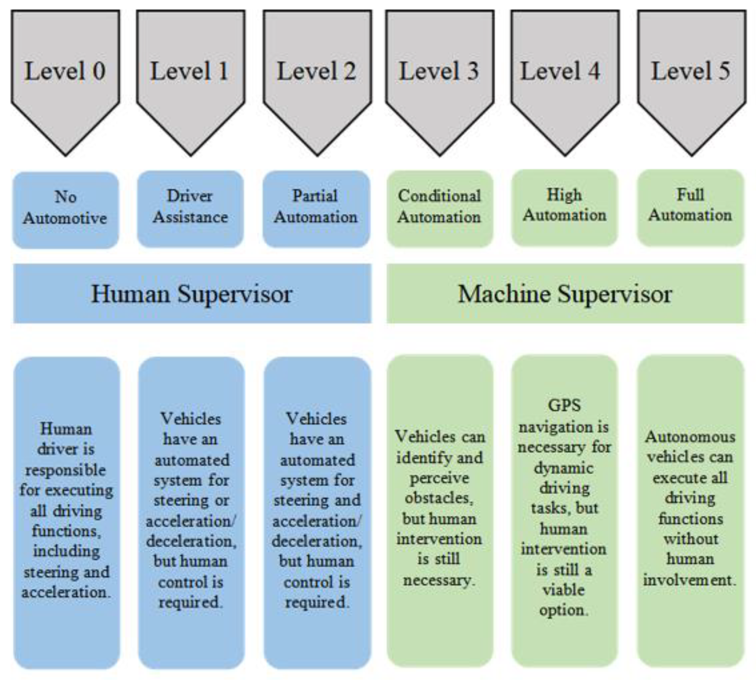
Figure 2.
Full autonomous navigation system. Senser Technology, fusion overview, V2V and V2I [4].
Figure 2.
Full autonomous navigation system. Senser Technology, fusion overview, V2V and V2I [4].
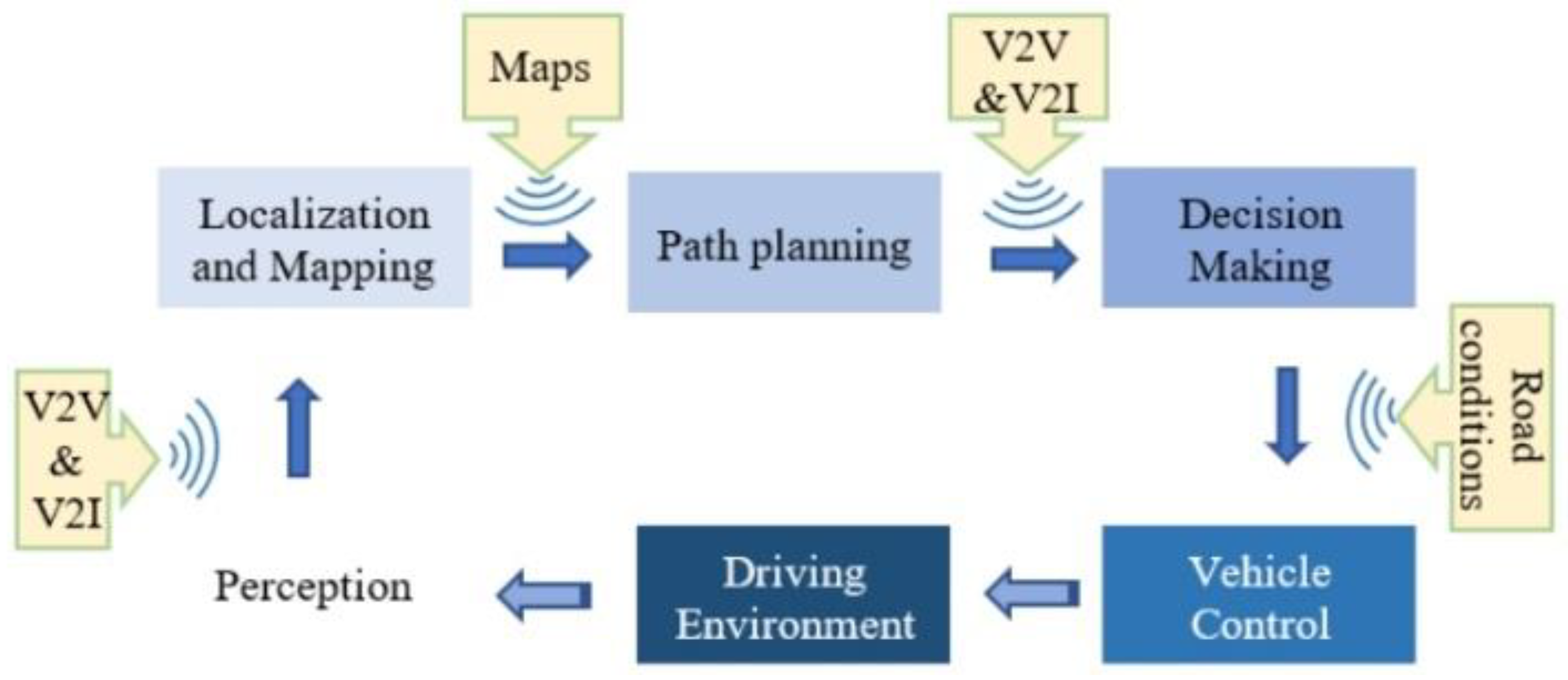
Figure 3.
Comparison among AV sensers with advantages and disadvantages [16–47].
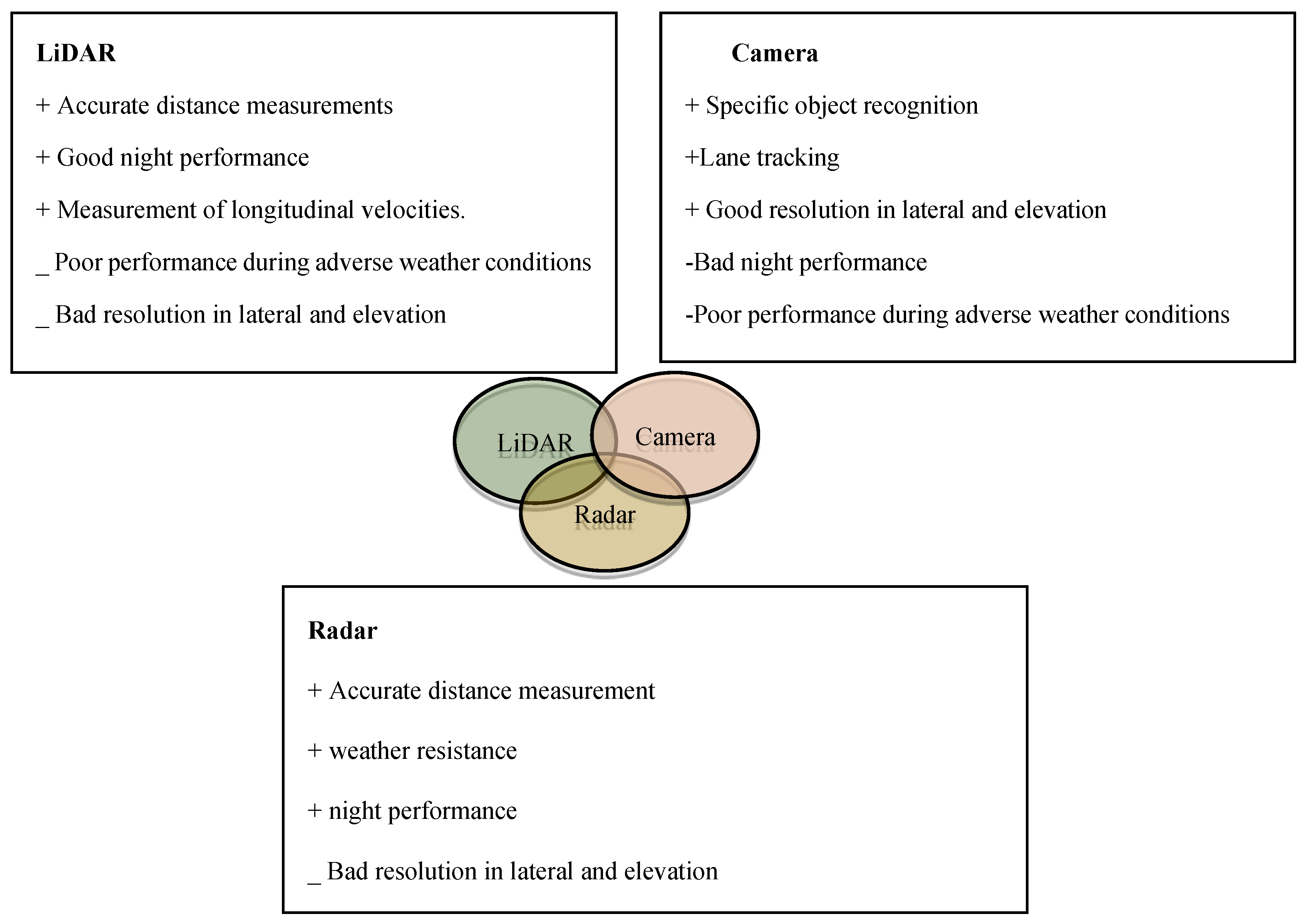
Figure 6.
MOST Ring Topology [27].
Figure 6.
MOST Ring Topology [27].
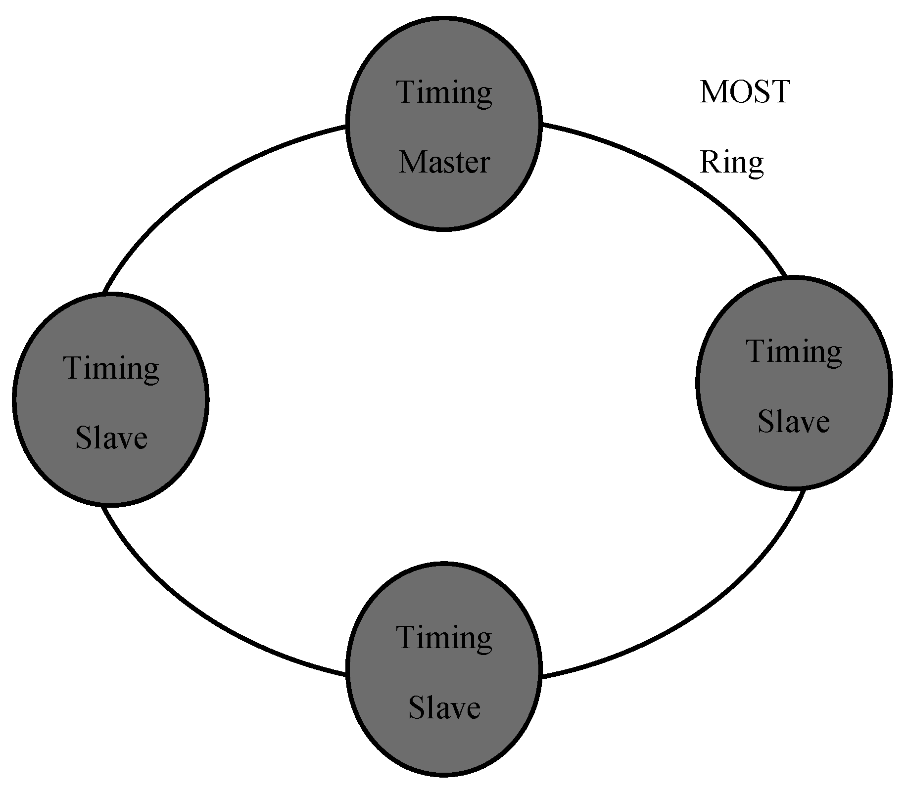
Figure 7.
MOST150 frame [27].
Figure 7.
MOST150 frame [27].

Figure 8.
FlexRay linear bus topology [27].
Figure 8.
FlexRay linear bus topology [27].
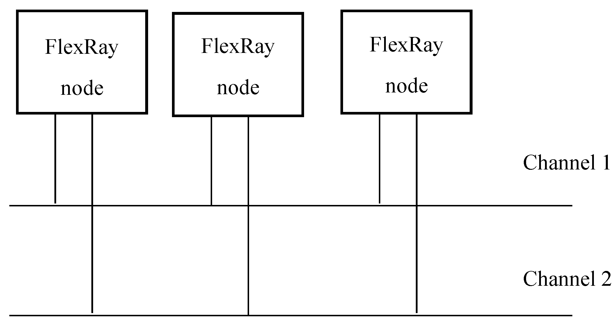
Figure 9.
FlexRay star topology [27].
Figure 9.
FlexRay star topology [27].
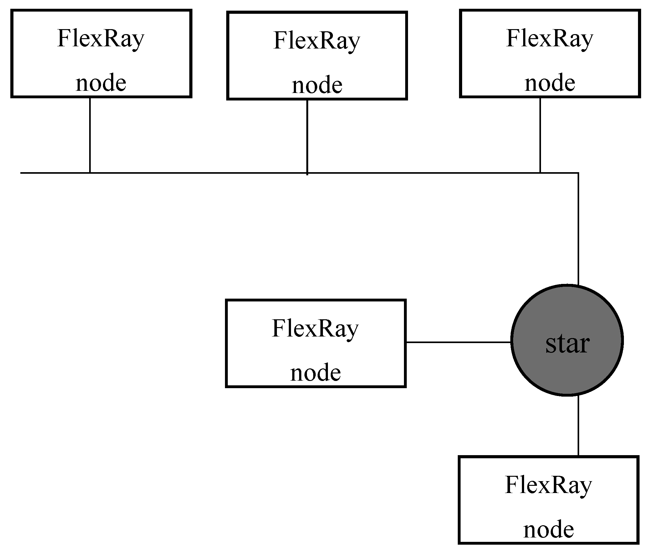
Figure 10.
FlexRay frame [24].
Figure 10.
FlexRay frame [24].
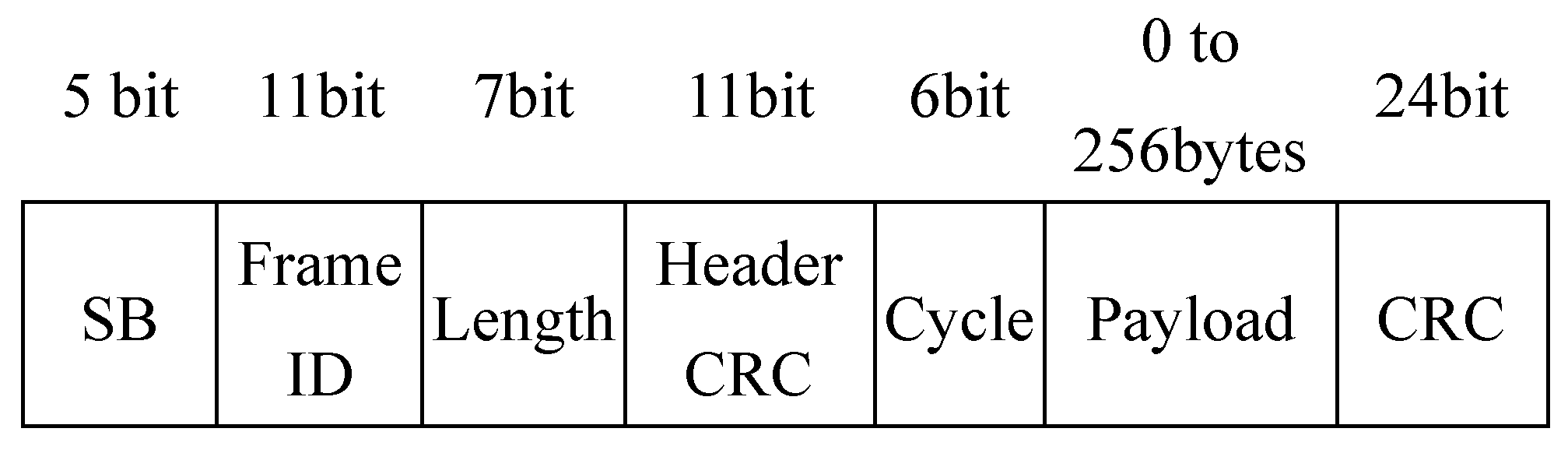
Figure 11.
IEEE 802.3 Ethernet frame [27].
Figure 11.
IEEE 802.3 Ethernet frame [27].
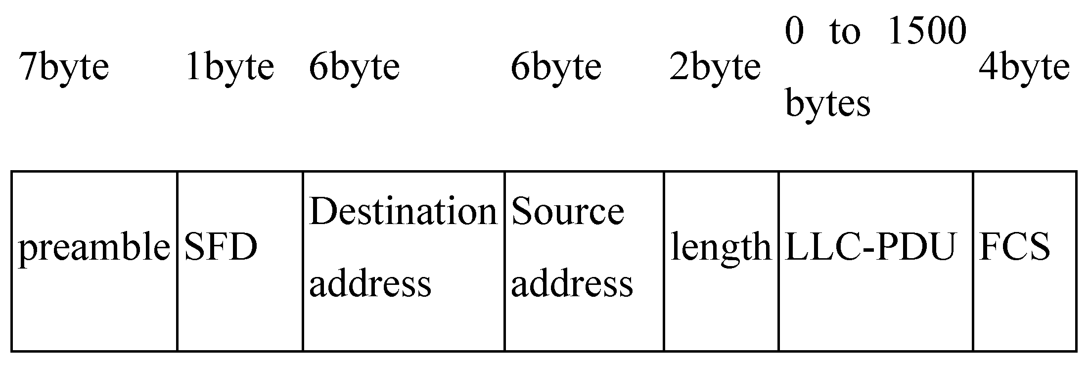
Figure 12.
Illustration of a hybrid scheme for AV intra-vehicle networking [22].
Figure 12.
Illustration of a hybrid scheme for AV intra-vehicle networking [22].
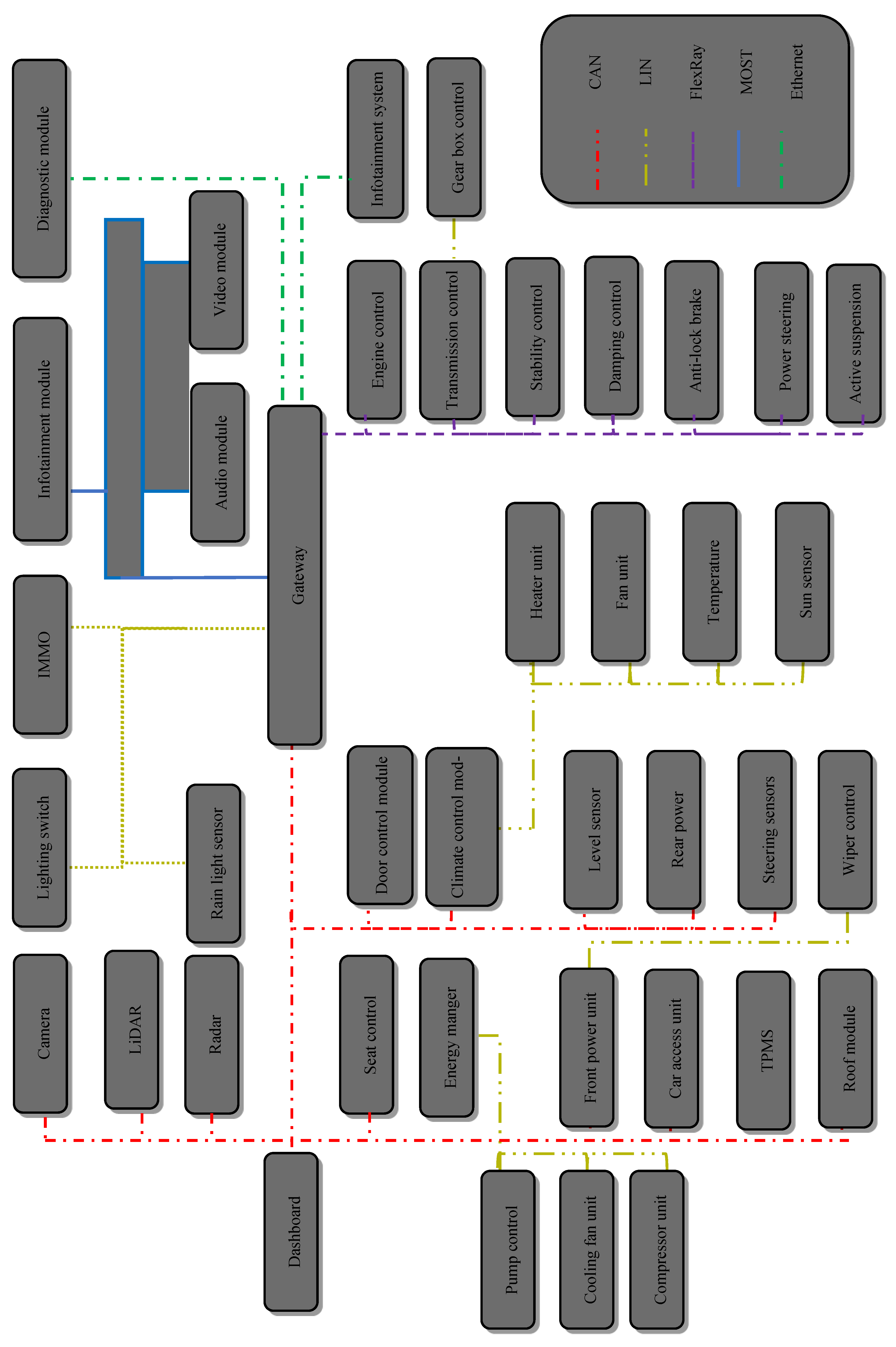

Table 1.
Delay deadline requirement for AV.
| Sensor | Delay Deadline (ms) |
| Radar | 10 |
| LiDAR | 10 |
| Camera | 10 |
| Control | 50 |
Table 2.
Comparison of AV technology [19].
Table 2.
Comparison of AV technology [19].
| Industry | Company | Camera Count | LiDAR Count | Radar Count | Level of Automation |
| Personal Vehicles |
Tesla | 8 | 0 | 1 | Level 2 |
| Google Waymo | 12 | 5 | 6 | Level 4 | |
| Baidu Apollo | 5 | 2 | 3 | Level 4 | |
| BMW Series 5 | 2 | 4 | 5 | Level 3 | |
| Argo AI, Cruise | 9 | 2 | 0 | N/A | |
| Public Transports (buses) |
Volvo | 6 | 3 | 2 | Level 2 |
| Public Transports (shuttles) |
Navya | 2 | 10 | 0 | Level 4 |
| EasyMile | 3 | 2 | 1 | Level 4 | |
| Public Transports (train) |
SNCF | 2 | 4 | 4 | level 4 |
| Smart Farming (tractors) |
John Deere | 3 | 0 | 0 | Level 2 |
| Smart Farming (robots) |
NAIO Technologies | 2 | 0 | 0 | Level 4 |
| Smart Farming (drones) |
DJI | 0 | 2 | 0 | Level 4 |
| Logistics | Mercedes-Benz | 5 | 3 | 2 | Level 4 |
| Freightliner | 6 | 4 | 2 | Level 4 |
Table 3.
Automotive functional domains [26].
Table 3.
Automotive functional domains [26].
| Functional Domain | Description | IVN technology |
| Powertrain | Control of engine and transmission | CAN, FlexRay |
| Chassis | Control of the vehicle stability and dynamics according to steering/braking solicitations and driving conditions (e.g. wind, ground surface) | CAN, FlexRay |
| Body and Comfort | Control of doors, windows, roof , seats and climate control, etc. | LIN, CAN |
|
Multimedia/ Infotainment |
Audio CD,DVD and MP3 players, TV, Rear Seat Entertainment, navigation information services, etc. | MOST, CAN |
| Human Machine Interface | Advanced display technologies | MOST, CAN |
| ADAS | Lane Departure Waring, Traffic Sign Recognition ,Night vision, Pedestrian detection, Parking assistant, etc. | CAN, FlexRay |
Table 4.
Advantages and Limitations of Sensors.
| Sensor Type | Advantages | Limitations |
| LiDAR | High accuracy, 3D mapping | Expensive, affected by weather |
| Radar | Works in all weather, measures speed | Low-resolution object identification |
| Cameras | Color and object recognition | Affected by lighting conditions |
| Inertial Navigation System (INS) | Precise vehicle movement tracking | Drift errors over time |
Disclaimer/Publisher’s Note: The statements, opinions and data contained in all publications are solely those of the individual author(s) and contributor(s) and not of MDPI and/or the editor(s). MDPI and/or the editor(s) disclaim responsibility for any injury to people or property resulting from any ideas, methods, instructions or products referred to in the content. |
© 2025 by the authors. Licensee MDPI, Basel, Switzerland. This article is an open access article distributed under the terms and conditions of the Creative Commons Attribution (CC BY) license (http://creativecommons.org/licenses/by/4.0/).
Copyright: This open access article is published under a Creative Commons CC BY 4.0 license, which permit the free download, distribution, and reuse, provided that the author and preprint are cited in any reuse.


