1. Introduction
In building structures and mechanical systems, non-linear vibration isolation is considered as effective method of protecting a structure and is becoming increasingly popular [
1,
2,
3,
4]. The non-linear vibration isolation device has the potential to significantly reduce the fundamental frequency of the protected structure to minimise the transmission of force or displacement even for low frequency excitation cases, where traditional vibration isolations are generally not very effective [
5].
Passive control devices are systems that do not require an external power source. The forces developed in these devices due to building movements are used by the devices themselves. These devices include basic isolation systems and tuned mass dampers (TMD), quazi zero stiffness QZS and friction pendulum (FPS) [
6,
7]
Previous research has demonstrated the importance of isolation bearings as they play a key role in facilitating the transmission of forces from the superstructure to the substructure [
3,
8,
9].
The QZS is a system generally used to damp vertical forces and its effectiveness has been demonstrated on several occasions by researchers [
9,
10,
11,
12,
13,
14].
Research on QZS dampers has been conducted to reduce earthquake-induced building movements. Several studies have evaluated the responses of QZS systems under both harmonic and random excitations [
15,
16].
The Friction Pendulum System (FPS) is frequently used in civil engineering structures for isolation purposes. Due to its geometrical design, the FPS provides an effective friction isolation system by combining sliding motion with restoring force [
17,
18,
19,
20,
21]. Some studies have evaluated the seismic reliability of an SPF-isolated base structure by treating isolator characteristics and principal earthquake characteristics as independent random variables [
22].
This paper uses a QZS-FPS configuration to damp horizontal forces in a structure. This paper evaluates the effect of horizontal ground excitation on the response of a structure isolated by an isolation system coupling consisting of a non-linear damper (QZS) and a friction pendulum (FPS).
2. Equation of Motion
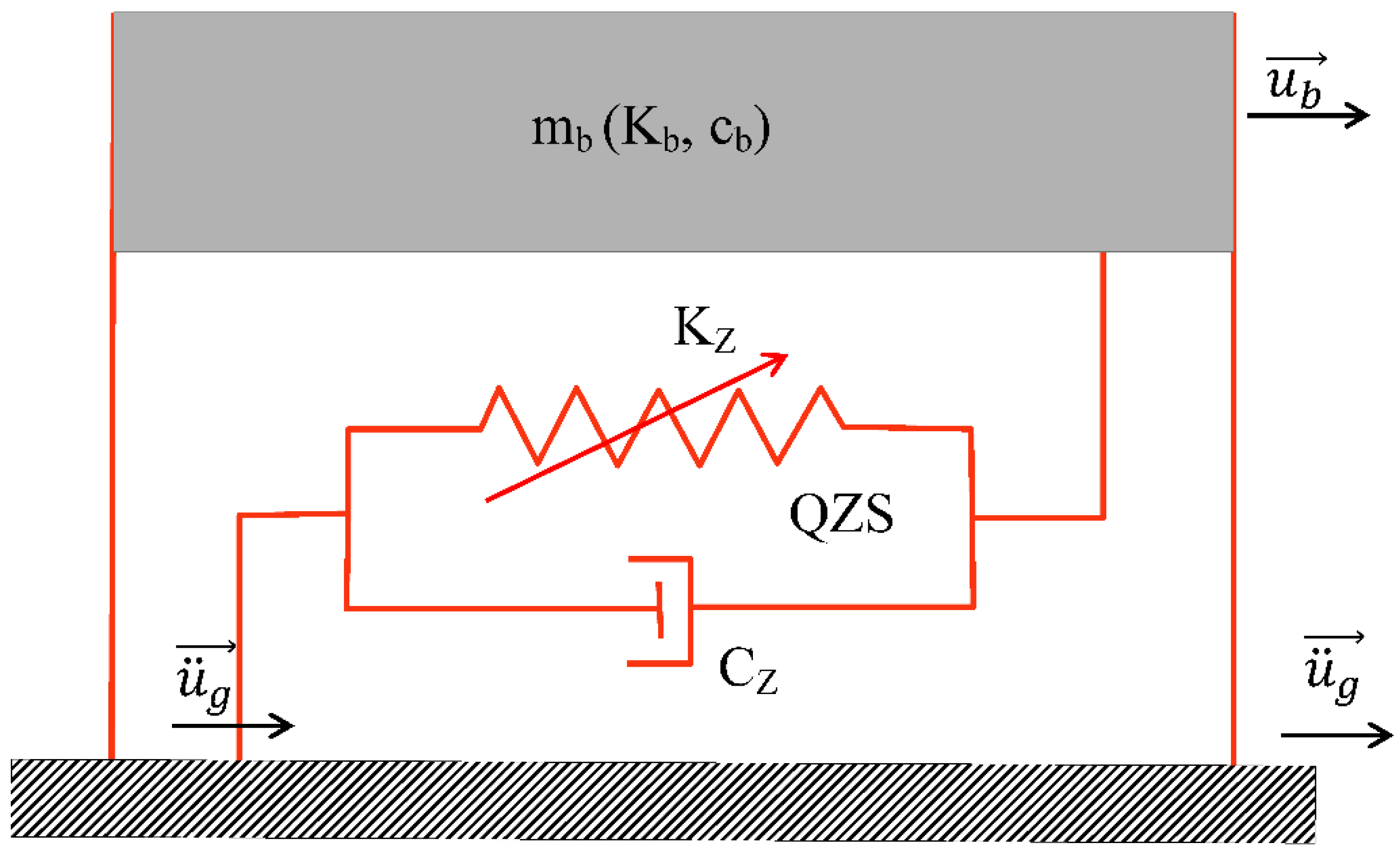
2.1. Equation of Motion for the Case of Quasi-Zero Stiffness
Figure 1 shows a QZS-isolated structure subjected to a horizontal external excitation (
) and whose response
is determined from Equation (1).
With:
the weight of the base
: the reaction of the ground due to the load of the building
: the inherent damping force of the base conferred on it by the various materials making it up
: the force of the non-linear elastic damper
: the elongation force of the structure imparted by the steels
: accelerations felt at the base (foundation)
mb: represents the mass of the base above the insulation system
: represents the damping ratio of the non-linear damper to that of the structure
: represents the ratio of the stiffness of the damper structure to that of the structure
The dimensionless form of the equation of motion is obtained from the time scale
and taking the excitation signal
where
is the seismic intensity scale which has the same dimension as the signal acceleration and
the time-dimensional function describing the time-dimensional function of the excitation signal is:
With:
For the scaled function
harmonic, i.e.
and using the harmonic balance [
23], the response of the structure will be expressed as;
, with β the scaled pulsation of the signal.
Neglecting the terms in sin(3(βτ)) Equation (5) then becomes:
From Equation (6) we can deduce;
Squaring Equations (7) and (8) and adding them together gives:
After posing ε=ε_b (1+γ), Equation (9) becomes:
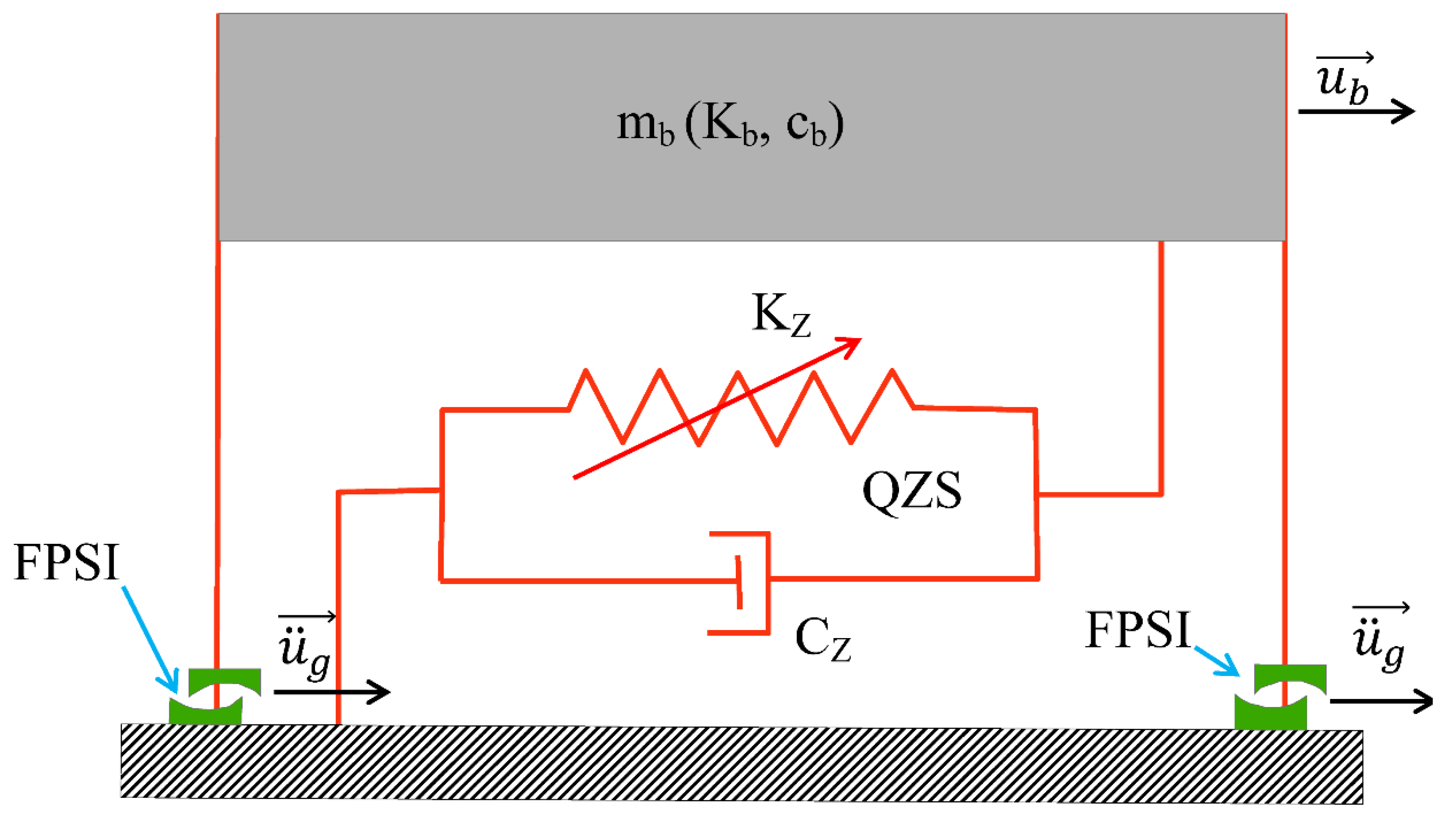
2.2. Equation of Motion for the Case of Quasi-Zero Stiffness Coupled to the FPS
Figure 2 shows the structure isolated by the coupling of the QZS and the FPS. The equation of motion governing the behaviour of this structure under external excitation is determined from Equation (11)
With:
the weight of the base
: the reaction of the ground due to the load of the building
: the inherent damping force of the base conferred on it by the various materials making it up
: the force of the non-linear elastic damper
: the force of the double FPS
: the elongation force of the structure conferred on it by the steels
: accelerations felt at the base (foundation)
mb: represents the mass of the base above the insulation system
: represents the ratio of the damping coefficient of the non-linear damper to that of the structure
: represents the ratio of the stiffness of the damper to that of the structure
: is the sliding friction coefficient
: stiffness constant of the structure
: stiffness constant of the non-linear damper
: maximum value of the coefficient of friction
From Equation (12) we obtain:
The principle used in Equation 3 allows us to obtain Equation (14) from Equation (13).
Assuming harmonic seismic excitation, i.e.
, the response of the structure will be expressed as:
[
23]
However,
Neglecting the terms in
Equation (15) becomes:
From Equation (16) we get the following Equation (17);
Squaring Equations (17) and (18) and adding them together gives:
Solving this equation gives the frequency response curve for stiff, soft and linear springs for different values of ε, with .
2.3. Case of Stochastic Excitation
In this case, the seismic loading (
) is represented as random sequences of white Gaussian noise, adjusted by filtering and time modulation of varying intensity, in the context of spectral density analysis. The filter characteristics determine the frequency distribution of these random stresses and are adjusted to correspond to rigid, intermediate or loose soil conditions, as appropriate. For this purpose, the Kanai-Tajimi filter modified by Clough and Penzien (Equation (20)) is used to model the different soil types.
represents the spectral level of white noise linked to the maximum acceleration of the ground.
Where is the peak ground acceleration (PGA); , , and are the filter parameters. [24, 25].
The maximum value of the recorded ground acceleration oscillates between 0.4 g and 0.6 g [26-28].
3. Results and Discussion
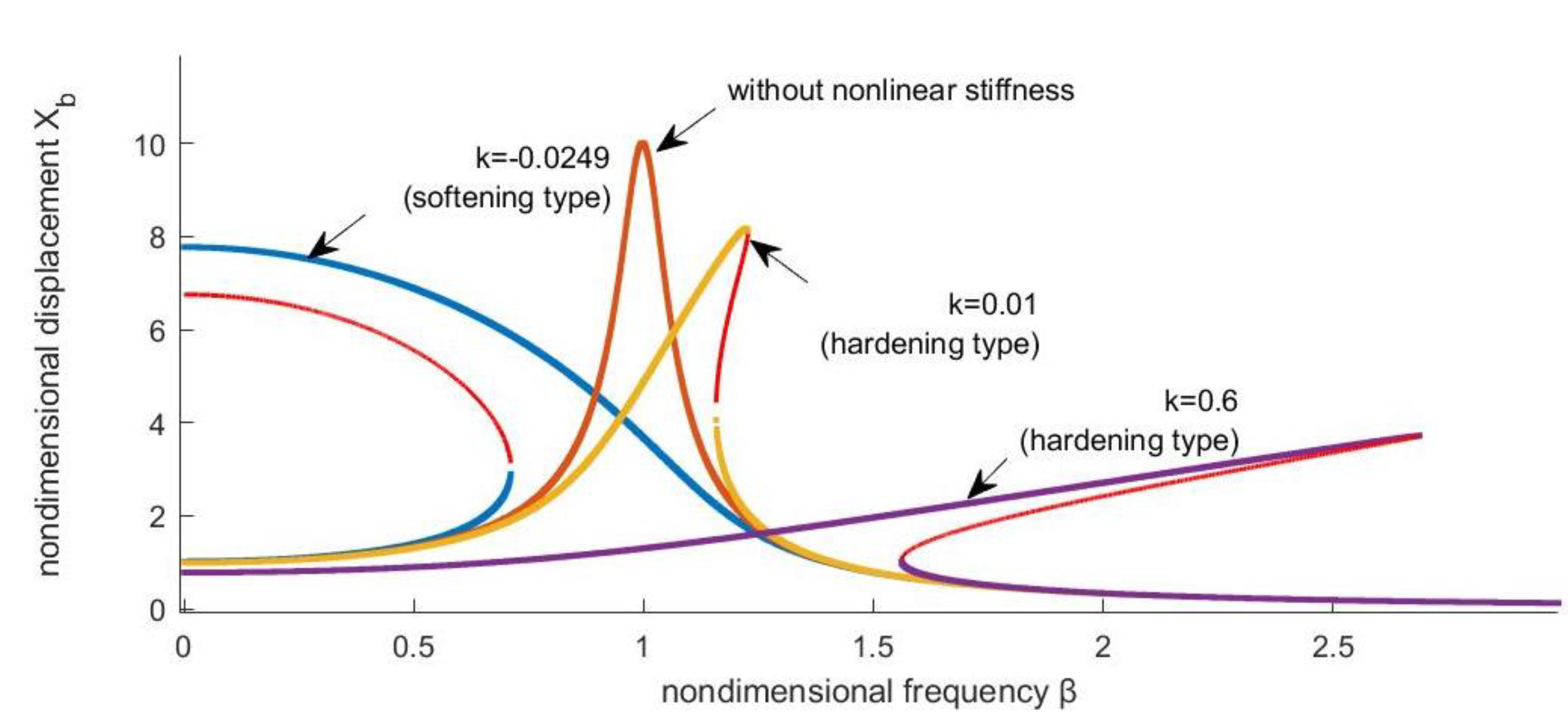
3.1. Amplitude-Frequency Response in the Case of a Harmonic Signal
Figure 3 shows the amplitude response of the non-isolated system isolated by the QZS according to its various characteristics as a function of the scaled frequency for a total system damping of 5%. In the case of a system isolated by a QZS with a softening stiffness (k=-0.0249 and k=-0.0030) the amplitude curves slope as the frequency increases, in other words the resonance frequency is inversely proportional to the amplitude of the oscillations. In contrast, for the system isolated by the rigid QZS (k=0.1000 and k=0.6000) the amplitude curves slope to the left, from which we deduce that the responses are weak at high resonance frequencies.
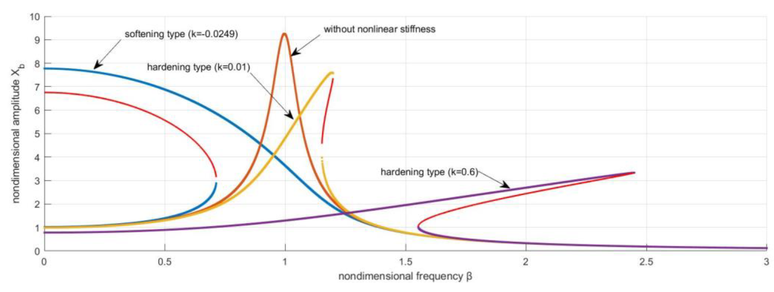
The amplitude-frequency responses of the system isolated by the FPS and by the QZS-FPS coupling are shown in
Figure 4 for ε=0.05. The slope of the amplitude-frequency response curves in
Figure 4 shows the persistence of the QZS non-linearity despite the QZS-FPS coupling. In addition, the maximum amplitudes of the responses of the structure for the case of soft-stiff QZS coupling with the FPS are greater than those of the structure isolated only with the FPS. This is quite the opposite of those where the structure is isolated by the rigid QZS coupling and the FPS, which are the lowest as the stiffness increases.
3.2. Amplitude Response for the Case of a Stochastic Signal
The various seismic signals were derived from Equation (17).
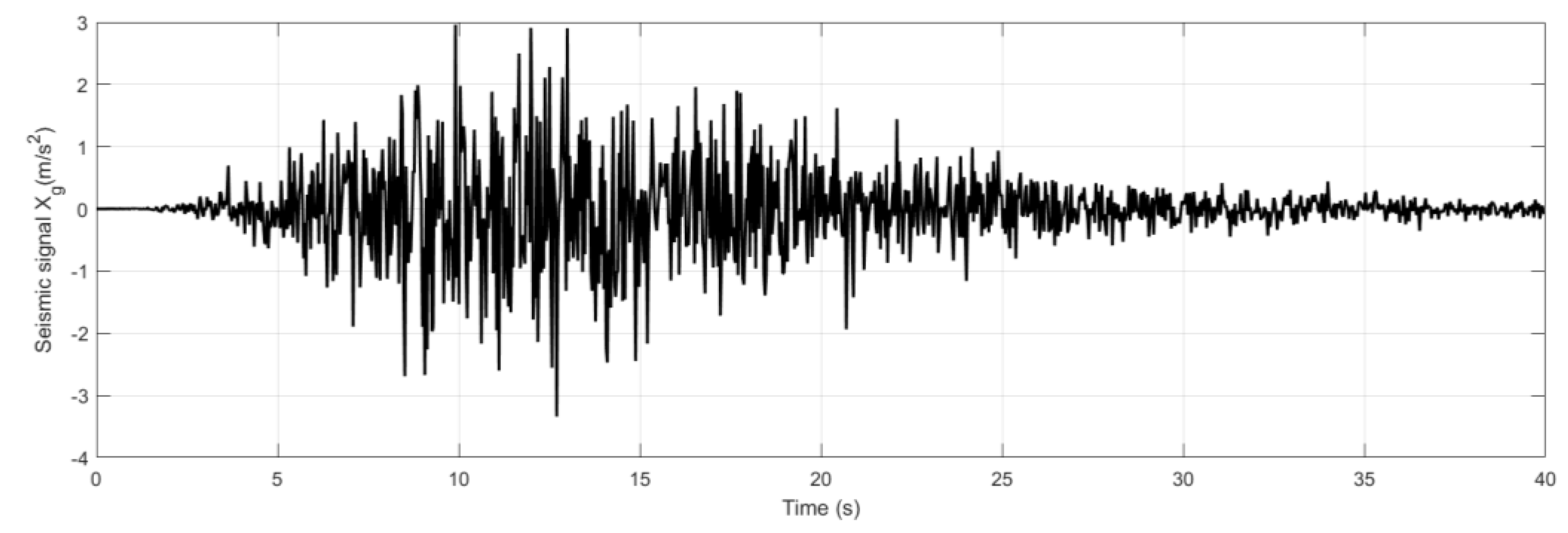
Case of soft ground
Figure 5 shows the time evolution of the seismic signal Xg, modelled according to the Kanal-Tajimi spectrum modified by Clough and Penzien. The signal shows amplitude variations between -4 and 3 over a period of 40 seconds. The oscillations observed are characterised by acceleration and deceleration phases, which are essential for analysing the dynamic response of structures.
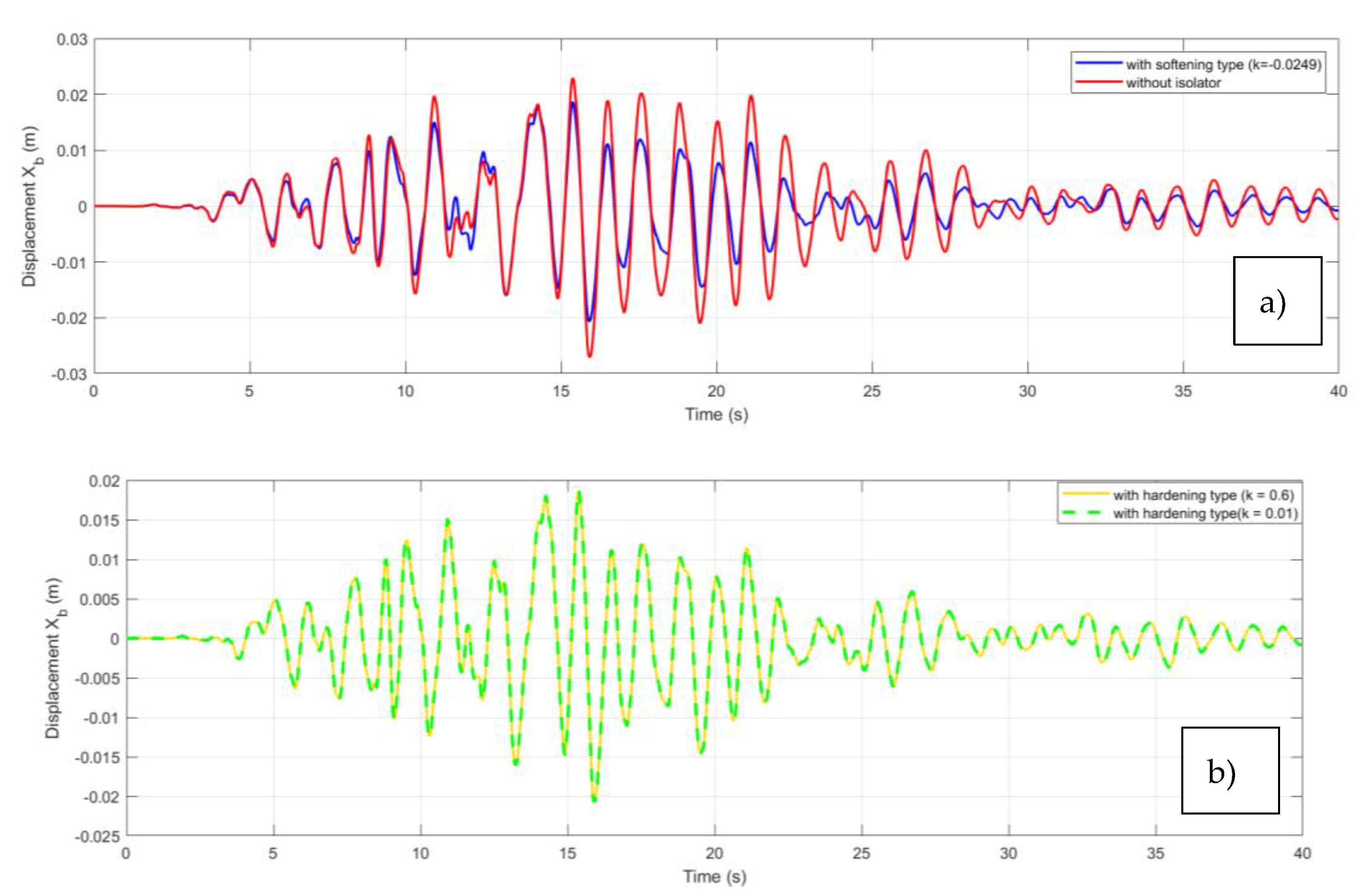
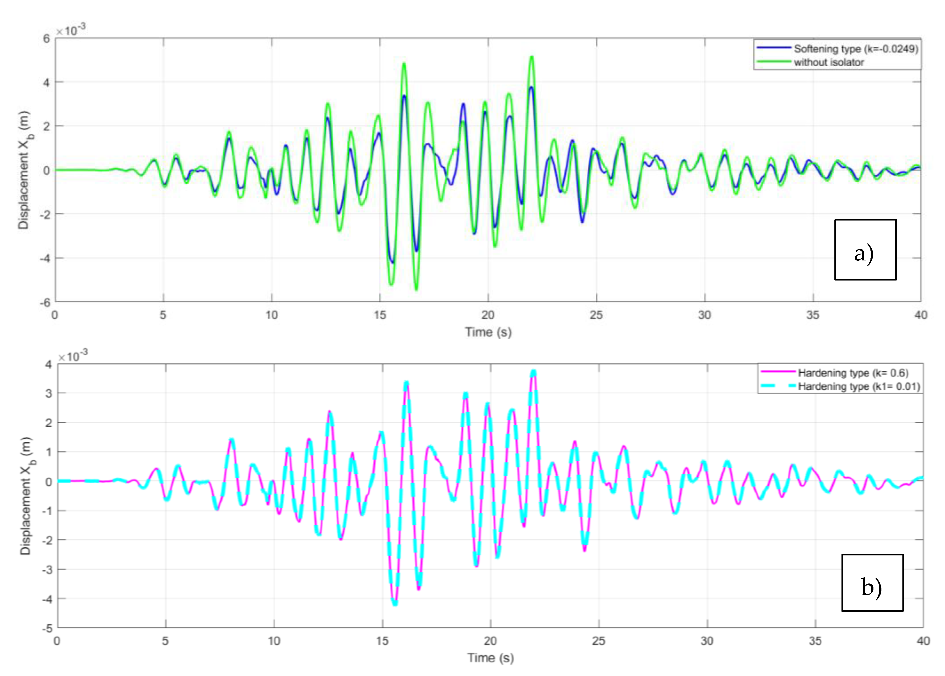
The response of the structure to this signal is shown in
Figure 6 for the different cases of isolation (QZS and QZS-FPS coupling). For an uninsulated structure, the amplitudes vary between -0.028 m and 0.026 m, while in the case of low stiffness insulation the amplitudes of the oscillations vary between -0.021 m and 0.019 m. The negative and positive displacements show that the building oscillates around its equilibrium position. Furthermore, the amplitudes of the oscillations in the case of rigid stiffness insulation vary between -0.021m and 0.019m. In other words, the amplitudes of the oscillations in the case of insulation with a soft stiffness are smaller than those of insulation with a rigid stiffness.
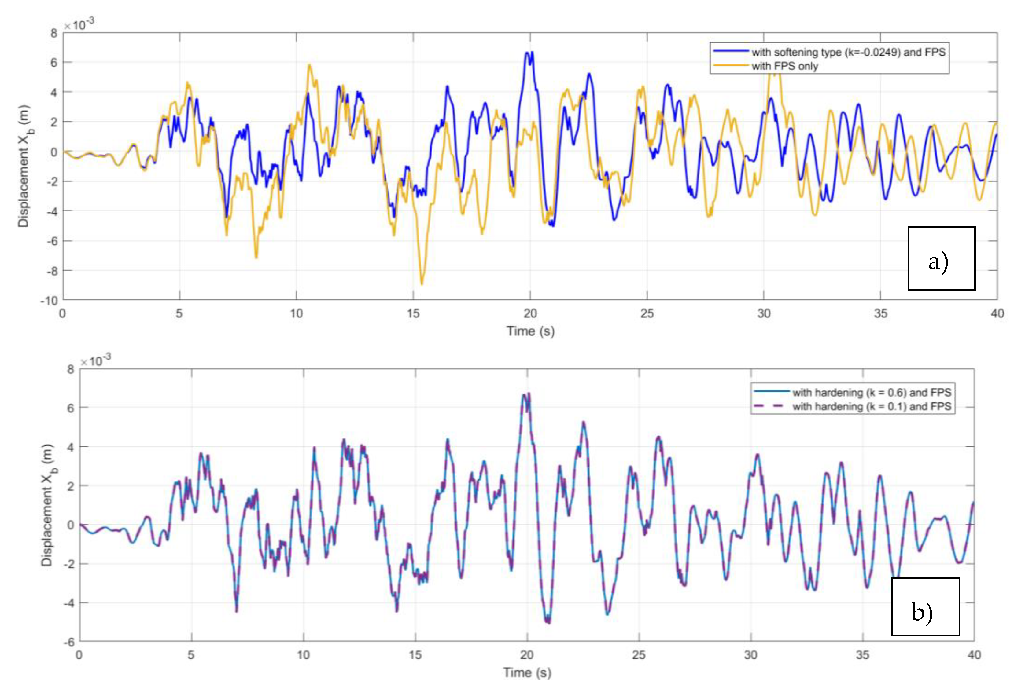
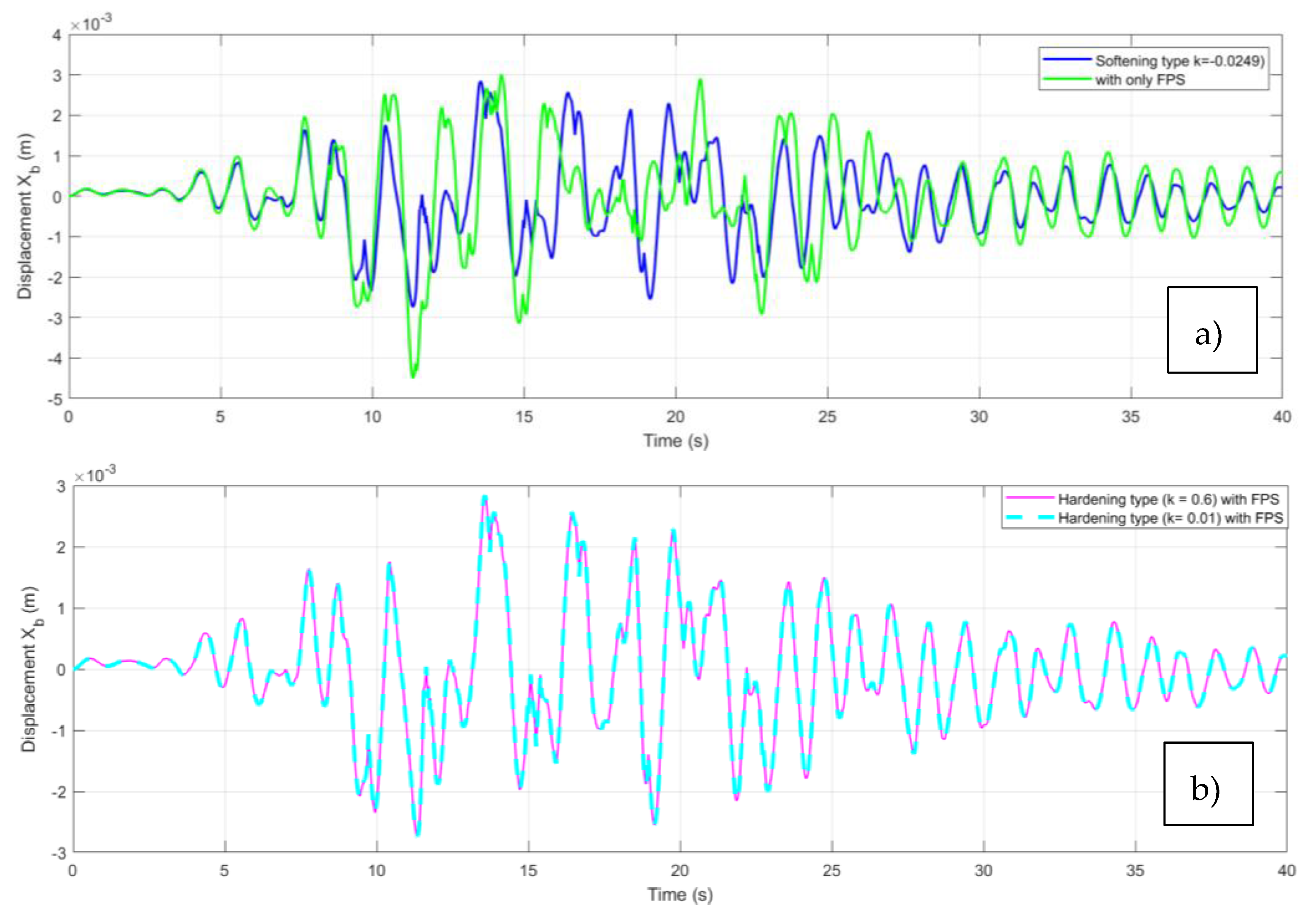
The response of the structure to the seismic signal in a soft ground environment is shown in
Figure 7. The amplitude of the oscillations for the case of a QZS coupling with soft stiffness -FPS varies between -0.0052 m and 0.0071 m while that isolated by the friction pendulum alone varies between -0.0094 m and 0.0065 m.
Figure 7b on the other hand shows that for a high stiffness damper the amplitude curve varies between -0.0056m and 0.0069m.
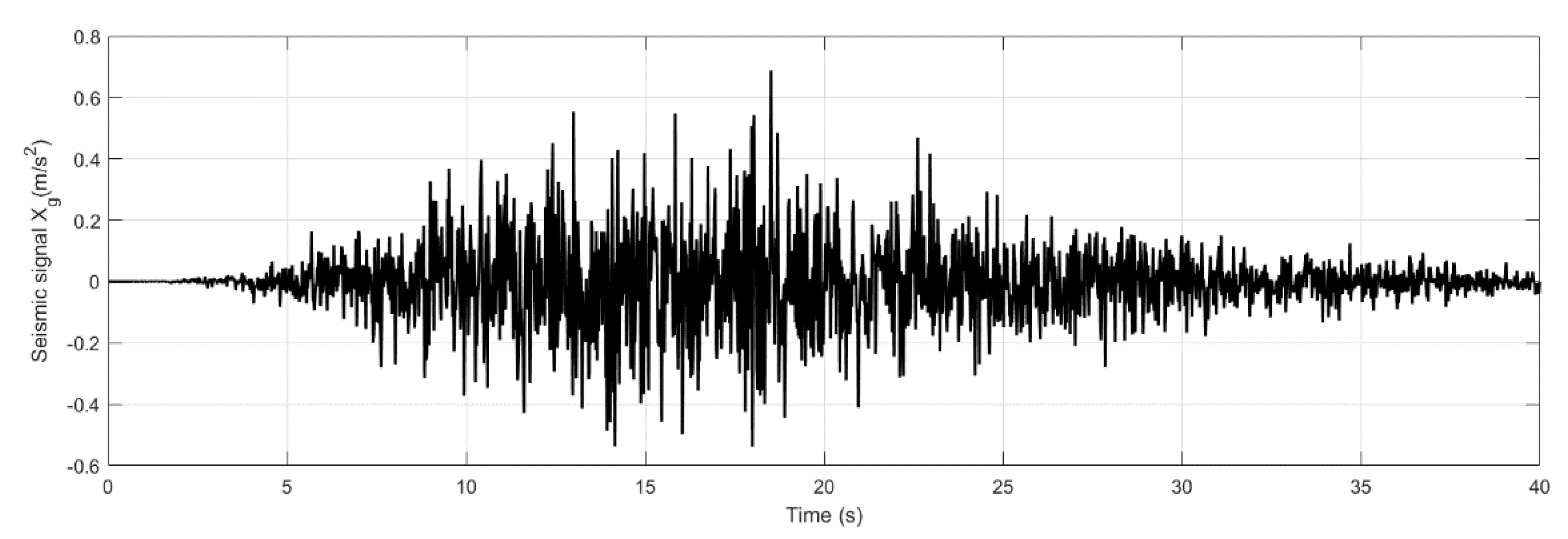
Case of hard ground
Figure 8 shows the temporal evolution of the Xg seismic signal in a rigid soil environment.
Figure 9 shows the time trace of the response of the structure. For the same seismic signal, the amplitudes are constant to a few decimal places in the case of rigid QZS, whereas the amplitudes of the oscillations decrease in the case of soft QZS.
Figure 10 shows the response of the structure under different types of insulation. In fact, the blue curve in
Figure 10a shows the evolution of the dependent variable (for example, performance or displacement) in a system where a softening with a coefficient k=-0.0249 is applied, in conjunction with SPF management, whereas the green curve shows the evolution of the same dependent variable in a system where only SPF management is applied. As for
Figure 10b, the interrupted curve represents the response of the structure isolated by the FPS-QZS coupling with rigid stiffness (k=0.6) and the solid line represents the FPS-QZS coupling with rigid stiffness (k=0.01).
Figure 6 shows that the structure isolated by the soft-stiff FPS-QZS coupling has a lower amplitude than that isolated by the QZS and the stiff FPS-QZS coupling.
3.3. Discussion
Figure 3 and
Figure 4 show the amplitude-frequency response of a structure that was initially uninsulated, then isolated by the QZS and by the FPS-QZS coupling at different stiffnesses. The curves observed in figure 4 show the importance of the non-linearity of the QZS compared with that of the friction pendulum [29, 30]. On the other hand, the reduction in the amplitude of oscillations and the reduction in unstable responses show that the FPS plays a major role not only in the performance but also in the stabilisation of the system. This effectiveness is illustrated by a decrease in oscillation amplitudes of around 30% on soft and hard ground in
Figure 7 and
Figure 10. In addition, figures 7 and 10 show that the FPS - QZS coupling with soft stiffness is the most effective under different types of soil, probably due to the performance of the QZS with soft stiffness, as shown in figure 6a and [
4].
4. Conclusions
Non-linear isolation devices are an emerging area of research and have, due to their promising potential, attracted considerable attention in the scientific community. The aim of this study was to evaluate the effect of horizontal ground excitation on the response of a structure isolated by a coupled system consisting of a non-linear damper (QZS) and a friction pendulum (FPS) with respect to the QZS.
- -
The FPS-QZS coupling with rigid stiffness can dampen the amplitude of the oscillations of the isolated structure by 30% with the QZS alone.
- -
-
The FPS-QZS coupling with soft stiffness can dampen the amplitude of the oscillations of the isolated structure by 40% with the QZS alone.
The soft stiffness FPS-QZS coupling dampers better than the rigid stiffness FPS-QZS coupling.
All this shows that the FPS-QZS coupling appears to be more effective than all the other isolators.
Author Contributions
Conceptualization, W.WRK. and P.N.N.; methodology, W.W.R.K., T.C.S., P.K.F.E., G.P.P.B.,A.M.P.N., M.D.E. and P.N.N.; software, W.W.R.K., T.C.S., P.K.F.E., G.P.P.B.,A.M.P.N., M.D.E. and P.N.N.; validation, W.W.R.K., T.C.S., P.K.F.E., G.P.P.B.,A.M.P.N., M.D.E. and P.N.N.; formal analysis, W.W.R.K., A.M.P.N. and P.N.N.; investigation, W.W.R.K., A.M.P.N. and P.N.N.; data curation, W.W.R.K., T.C.S., P.K.F.E., G.P.P.B.,A.M.P.N., M.D.E. and P.N.N.; validation, W.W.R.K., T.C.S., P.K.F.E., G.P.P.B.,A.M.P.N., M.D.E. and P.N.N.; writing—original draft preparation, W.W.R.K., T.C.S., P.K.F.E., G.P.P.B.,A.M.P.N., M.D.E. and P.N.N.; validation, W.W.R.K., T.C.S., P.K.F.E., G.P.P.B.,A.M.P.N., M.D.E. and P.N.N.; writing—review and editing, W.W.R.K., T.C.S., P.K.F.E., G.P.P.B.,A.M.P.N., M.D.E. and P.N.N.; validation, W.W.R.K., T.C.S., P.K.F.E., G.P.P.B.,A.M.P.N., M.D.E. and P.N.N.; visualization, W.W.R.K., M.D.E.; supervision, P.N.N.; project administration, M.D.E. and P.N.N.; All authors have read and agreed to the published version of the manuscript.
Data Availability Statement
The data presented in this study are available on request from the corresponding author.
Conflicts of Interest
The authors declare no conflicts of interest.
References
- SNOWDON, J.C. Vibration isolation: use and characterization. J. Acoust. Soc. Am. 1979, 66(5), 1245–1274. [Google Scholar]
- Alabuzhev, P. M. Vibration protection and measuring systems with quasi-zero stiffness. CRC Press. 1989. [Google Scholar]
- GUDAINIYAN, J.; GUPTA, P. K. A comparative study on the response of the L-shaped base isolated multi-storey building to near and far field earthquake ground motion. Forces in Mechanics. 2023, 11, 100191. [Google Scholar]
- Hui, Y.; Zhou, T.; Liu, J.; Jia, H.; Zhang, S. Seismic response study of multi-span continuous beam bridges near faults considering permanent displacement attenuation effects. In Structures. 2024, 69, 107516. [Google Scholar] [CrossRef]
- KANG, X.; LI, S.; YAN, C.; JIANG, X.; Hou, H.; FAN, Z.; MAO, D.; Huang, Q. Enhancing the seismic performance of adjacent building structures based on TVMD and NSAD. Buildings. 2023, 13(8), 2049. [Google Scholar]
- PISAL, A.Y.; JANGID, R. S. Dynamic response of structure with tuned mass friction damper, Int. J. Adv. Struct. 2016, 4, 363–377. [Google Scholar] [CrossRef]
- Yang, Y.; Zhou, Z.; Wang, X.; Zhang, X.; Wang, Z. 2.5-dimension soil seismic response to oblique incident waves based on exact free-field solution. Frontiers of Structural and Civil Engineering, 2024, 18, 2–216. [Google Scholar] [CrossRef]
- HASSAN, A. L.; BILLAH, A. M. Influence of ground motion duration and isolation bearings on the seismic response of base-isolated bridges, Eng. Struct. 2020, 222, 111129. [Google Scholar]
- Zhao, Z.; Wang, Y.; Chen, Q.; Qiang, H.; Hong, N. Enhanced seismic isolation and energy dissipation approach for the aboveground negative-stiffness-based isolated structure with an underground structure, Tunnelling and Underground Space Technology, 2023, 134, 105019.
- Li, H.; Li, Y.; Li, J. Negative stiffness devices for vibration isolation applications: a review. Advances in Structural Engineering, 2020, 23, 8–1739. [Google Scholar] [CrossRef]
- WU, X.; WANG, J.; ZHOU, J. Seismic performance analysis of a connected multitower structure with FPS and viscous damper, Shock and Vibration, 2018, 2018, 1, 1865761.
- XIONG, M.; HUANG, Y. Novel perspective of seismic performance-based evaluation and design for resilient and sustainable slope engineering, Engineering geology, 2019, 262, 105356.
- Zhang, Z.; Bi, K.; Hao, H.; Sheng, P.; Feng, L.; Xiao, D. Development of a novel deformation-amplified shape memory alloy-friction damper for mitigating seismic responses of RC frame buildings, Engineering Structures, 2020, 216, 110751.
- Chen, B.; Qiu, Y.; Xiong, J.; Liu, Y.; Xu, Y. Seismic performance and optimization of a novel partial seismic isolation system for frame structures. Buildings, 2022, 12, 7–876. [Google Scholar]
- ABOLFATHI, A. Can a nonlinear quasi-zero-stiffness spring improve the ride quality of a vehicle. Vehicle System Dynamics, 2024, 62,2, 330-346.
- JIN, Z.; CHEN, K.; HE, J. Improving vehicle’s seismic safety by equipping railway bridges with FPB and misalignment control device. Advances in Bridge Engineering, 2022, 3, 1, 4.
- NAEIM, F.; KELLY, J.M. Design of seismic isolated structures: from theory to practice. John Wiley & Sons, 1999.
- Wang, M.; Sun, F.F.; Yang, J.Q.; Nagarajaiah, S. Seismic protection of SDOF systems with a negative stiffness amplifying damper. Engineering Structures, 2019, 190, 128–141. [Google Scholar]
- CHEN, X.; WU, P.; LI, C. Seismic performance assessment of base-isolated tall pier bridges using friction pendulum bearings achieving resilient design. Structures, 2022, 618-629.
- Saboo, A.; Khan, M.; Kumar, M.; Sajish, S.D. Influence of seismic isolation on the earthquake response of internal components in a fast reactor. Nuclear Engineering and Design, 2023, 413, 112522.
- DU, Y.; HAN, B.; HONG, N. Dynamic response and failure modes of base-isolated frame structures subjected to earthquakes under dynamic bearing removal scenarios. Journal of Building Engineering, 2023, 72, 106556.
- Castaldo, P.; Palazzo, B.; Della, P.V. Seismic reliability of base-isolated structures with friction pendulum bearings. Engineering Structures, 2015, 95, 80-93.
- DAL BO, L.; TURCO, E.; GARDONIO, P. Electromagnetic and piezoelectric time-varying units for the control of flexural vibrations of thin-walled structures. Mechanics of Advanced Materials and Structures, 2023, 30, 5, 1083-1094.
- Clough, R.W.; Penzien, J. Dynamics of Structures, Mc Graw-Hill, 2nd edition, New York, 1993.
- HUO, Z.Y.; KHALIQUE, C.M. Stochastic seismic analysis of structures with nonlinear eddy current dampers. Journal of Low Frequency Noise, Vibration and Active Control, 2023, 42, 1, 69-79.
- KARIM, K.R.; YAMAZAKI, F. Effect of earthquake ground motions on fragility curves of highway bridge piers based on numerical simulation. Earthquake engineering & structural dynamics, 2001, 30, 12, 1839-1856. 1839; 12. [Google Scholar]
- AMBRASEYS, N.N.; DOUGLAS, J. Magnitude calibration of north Indian earthquakes. Geophysical Journal International, 2004, 159, 1, 165-206.
- ZENTNER, I.; POIRION, F. Enrichment of seismic ground motion databases using Karhunen–Loève expansion. Earthquake Engineering & Structural Dynamics, 2012, 41, 14, p. 1945-1957.
- Zhaozhao, M.; Ruiping, Z.; Qingchao, Y. Recent advances in quasi-zero stiffness vibration isolation systems: an overview and future possibilities. Machines, 2022, 10, 813.
- Abolfathi, A. Can a nonlinear quasi-zero-stiffness spring improve the ride quality of a vehicle? Vehicle Syst. Dyn. 2023, 2, 330–346. [Google Scholar]
|
Disclaimer/Publisher’s Note: The statements, opinions and data contained in all publications are solely those of the individual author(s) and contributor(s) and not of MDPI and/or the editor(s). MDPI and/or the editor(s) disclaim responsibility for any injury to people or property resulting from any ideas, methods, instructions or products referred to in the content. |
© 2025 by the authors. Licensee MDPI, Basel, Switzerland. This article is an open access article distributed under the terms and conditions of the Creative Commons Attribution (CC BY) license (https://creativecommons.org/licenses/by/4.0/).