Submitted:
04 March 2025
Posted:
05 March 2025
You are already at the latest version
Abstract
Historic infrastructure preservation demands innovative and sustainable methodologies that safeguard structural integrity while minimizing environmental impact. This study explores the application of Remotely Piloted Aircraft Systems (RPAS) for the non-invasive inspection of the Requejo Bridge, a centennial metallic arch bridge that spans the Duero River within a protected natural environment in Spain. Through high-resolution aerial surveys, RPAS technology enabled the exhaustive assessment of areas traditionally difficult to access, identifying localized corrosion and material degradation critical for preventive conservation planning. By eliminating the need for scaffolding and heavy machinery—elements that pose significant ecological risks to sensitive landscapes—the drone-based inspections substantially reduced carbon emissions and resource consumption, while optimizing operational costs and minimizing workplace hazards. The findings confirm that RPAS not only enhance the accuracy and efficiency of structural diagnostics but also embody a sustainable maintenance strategy aligned with multiple Sustainable Development Goals (SDGs), including climate action, responsible resource use, and occupational safety. This research advocates for the widespread adoption of drone-assisted methodologies in heritage infrastructure management, offering an environmentally responsible, economically viable, and safer alternative that extends the service life of historic structures through proactive and minimally invasive interventions.
Keywords:
sustainable conservation
; heritage management
; remote inspection
; environmental impact reduction
; structural and occupational safety
1. Introduction
The Requejo Bridge, also known as the Pino Bridge, is an impressive engineering work that spans the Duero River. The bridge is located in the province of Zamora, Spain (Figure 1), with its exact position defined by the following coordinates:
- UTM Coordinates (Zone 29):
- X (UTM): 739,444.16
- Y (UTM): 4,604,980.52
- Geographic Coordinates:
- 41°33'38.42"N
- 6°07'42.92"W
This is a metallic arch bridge, a remarkably innovative structure for the time it was built (Figure 2). Its design harmonizes functionality and aesthetics [1], featuring a striking central arch that supports the deck via metallic uprights.
The bridge spans a total length of 190 meters, rising more than 90 meters above the Duero riverbed.
Designed in the late 19th century and constructed in the early 20th century, its primary purpose was to facilitate communication between the Zamora regions of Aliste and Sayago, specifically linking the municipalities of Fonfría (located in Aliste, which had 1,347 inhabitants in 1897 [2]) and Fermoselle (located in Sayago, which had 4,569 inhabitants in 1897 [3]).
The bridge was conceived to traverse the Duero's riverbanks in an area characterized by deep canyons and rugged landscapes (Figure 2 and Figure 3). This, coupled with its structural typology and striking beauty, has made the bridge a visual landmark, seamlessly integrating into the Arribes del Duero—a protected area recognized for its high natural and scenic value and significant tourist interest [4].
Before its construction, the only direct connection between the towns near the bridge, Pino del Oro (in the Aliste region) to the north and Villadepera (in the Sayago region) to the south (Figure 1), was a barge that crossed the river using mooring cables [5].
The earliest references to the bridge's planning date back to the mid-19th century. Its first proponent was engineer and future Prime Minister Práxedes Mateo Sagasta, who, upon being elected as a deputy for the Zamora constituency, expressed his commitment to supporting this project [6]. Years later, Eduardo López Navarro evaluated an alternative location, approximately two kilometers downstream from the final site. This proposal featured a significantly lower grade and a construction solution based on two cast-iron spans [7], [8].
Due to the bridge’s strategic importance to the region, all parliamentary candidates pledged to advance its construction. However, it was Federico Requejo Avedillo, a native of Sayago, who, during his tenure at the General Directorate of Public Works [9], secured a feasibility study for a road connecting Fonfría to the Salamanca-Fermoselle highway, incorporating the bridge as part of the project [8]. For this reason, the Pino Bridge is also known as the Requejo Bridge.
The final approved project, designed by engineer José Eugenio Ribera in 1897, faced significant challenges during its execution. Initially, no contractors submitted bids for the initial tenders due to the complexity of the assembly process [10]. The Asturian company Duro Felguera took on the project but encountered difficulties during the bridge's assembly, ultimately transferring the work to another company, Montajes. However, Montajes also had to suspend and abandon the project due to technical complications. The project eventually returned to Duro Felguera, which, under the direction of Galician engineer Robustiano Fernández and with the support of local labor, successfully completed the bridge's construction [4]without any reported incidents or accidents during the arch assembly [8]. The bridge components were manufactured at the company's main plant in La Felguera, in the Principality of Asturias.
The design proposed by José Eugenio Ribera (Ribera Dutaste, 1897; Ribera Dutaste, 1914) envisioned a metallic bridge to span the Duero. As the first steel arch bridge in Spain, upon its inauguration on September 15, 1914, it became the longest-span bridge (120 meters between arch supports) and the highest bridge over a river (90 meters) in the country (Figure 4). With this project, Ribera challenged Eiffel’s designs by successfully constructing a lowered-arch bridge (Fernández García, 1914), which was lighter than those designed by the French engineer (Figure 5).
The bridge accommodates the ZA-321 regional road, enabling vehicles to cross the Duero. The roadway is a two-way single-lane road, with alternating traffic flow not regulated by traffic lights; instead, a priority sign (R-6) is placed at the eastern abutment (Pino del Oro side, right bank of the Duero). At the western abutment (Villadepera side, left bank of the Duero), a priority sign (R-5) is displayed in the opposite direction.
Vehicle weight is restricted to 15 tons, as indicated by multiple signs, and speed limits of 30 km/h are enforced at both bridge approaches (R-301 signs). Pedestrian access is facilitated by sidewalks along both sides of the bridge.
The structure is located within the central basin of the Duero River, which is filled with Cambrian and Precambrian materials [11]. The dominant lithology consists of schists and fine-grained gneisses interspersed with quartzite layers (Figure 6). Prior observations (Figure 2 and Figure 3) provide context for the bridge’s integration within the Duero canyon.
From a geotechnical perspective, the site consists of a plutonic outcrop of gneissic rocks, offering a combination of magmatic, migmatitic, and gneissic formations, which provide favorable lithological conditions. These materials are impermeable, with limited internal drainage due to fracturing and active surface runoff. Consequently, the area exhibits high load-bearing capacity and negligible settlement, making construction conditions generally favorable. Additionally, the region has very low seismic risk [12].
To systematically describe the structural elements of the bridge, this study designates the abutment with the lowest kilometer point—aligned with the kilometer markers of the ZA-321 road that runs over the bridge—as the first abutment. This abutment is closest to the town of Pino de Oro, situated on the right bank of the Duero River (eastern abutment; the left abutment in Figure 2 and Figure 4). The right and left sides of the bridge are defined according to the direction of increasing kilometer points. All referenced subcomponents are numbered from left to right (Figure 2 and Figure 4), following the east-to-west direction of the bridge, from Pino de Oro to Villadepera.
As previously mentioned, the structure is a metallic arch bridge with a deck located above the arch, spanning a total length of 190 meters between abutments (Figure 4). It consists of three distinct sections (Figure 2): a central span, represented by the metallic lattice arch, and two approach spans composed of metallic trestles supporting the metallic deck (Figure 7).
In the central section, the deck is supported directly by the arch through metallic uprights of varying height, ranging from 18.50 meters at the ends to 0.95 meters at the center of the arch (Figure 4 and Figure 7). The arch is founded on four concrete footings (Figure 8), with articulations secured by anchoring bars.
The uprights are anchored to the arch using gusset plates fastened with bolts to the main girders of the arch (Figure 9). The arch spans 120 meters between supports, featuring a reduced-rise design with a 23.42-meter rise (Figure 4) and a clearance of 90 meters above the river’s water surface. The arch’s cross-section varies, with a maximum width of 8.30 meters at the supports, tapering to 4.50 meters at the midspan, and incorporating a 1:12 slope in both arch elevations.
In the approach spans, the deck is supported directly by metallic trestles, which, in turn, rest on concrete foundations (Figure 2, Figure 4, and Figure 7). Similar to the uprights, the trestles are anchored to the concrete foundations using gusset plates secured with four 25-mm diameter bolts.
The substructure elements (uprights, trestles, bracing members, and the arch) are composed of L-section steel profiles and steel plates, all meticulously riveted.
The deck has a total width of 6.70 meters and consists of a cambered metallic framework (Figure 10), topped with a 0.14-meter-thick reinforced concrete layer that forms the alternating one-way traffic lane, which is 4.30 meters wide. This platform was installed in 2013, reducing the overall deck weight by replacing the previous structure, which consisted of a 0.40-meter-thick macadam and asphalt layer [13].
The deck is supported by the concrete abutments through four metallic bearings, each composed of three rollers.
The deck is further extended by cantilevered sections, each 1.00 meter wide, constructed from steel plates forming the sidewalks, which are supported by metallic brackets. The section is completed with steel railings on both deck elevations.
The deck follows a horizontal profile, incorporating a 2% transverse slope for water drainage. The roadway features metallic gutters on both sides to collect runoff water.
At the deck extremities, expansion joints made of reinforced elastomer and four inspection chambers providing access to the deck bearings are installed. Both the expansion joints and the inspection chambers were improvements implemented during the 2013 rehabilitation works [13].
Due to its historical and technical significance, the Requejo Bridge has been recognized as an Industrial Heritage Site in Spain and included in the list of the 100 most important elements of Spanish industrial heritage [14]. Undoubtedly, it represents a historical structure of exceptional heritage value that deserves preservation.
2. Objectives
Based on the observations presented, the Requejo Bridge—rising over 90 meters above the Duero River bed and exhibiting a design that restricts access to critical structural areas—represents an optimal and highly relevant case for assessing the effectiveness of drones in the inspection of heritage metallic structures. Beyond the technical challenges, the bridge’s historical, cultural, and aesthetic significance further underscores the importance of this inspection.
Accordingly, this study aims to investigate and validate the use of drones as an advanced tool for conducting high-precision visual inspections of heritage metallic structures, with the Requejo Bridge serving as a case study. If its applicability is confirmed, this approach could fundamentally transform the methodology for inspecting complex structures by improving safety, reducing costs, and optimizing execution times.
The collected data will facilitate the identification of not only reactive solutions (addressing existing damage) but also preventive strategies that contribute to extending the bridge’s service life while safeguarding its historical and functional integrity. This aligns with a broader objective of leveraging advanced microtechnological tools to enhance structural assessment and maintenance protocols.
This case study serves as a pilot test with the potential for application to similar structures. The research seeks to extrapolate insights and methodologies to a broader framework, fostering the integration of drone technology into future inspection practices.
While the study predominantly adopts a technical perspective, it also emphasizes the historical and aesthetic significance of the bridge. It is anticipated that this article will contribute to increasing awareness of the imperative to preserve such structures, positioning them within the framework of cultural and tourism-oriented sustainable development strategies.
3. Methodology
Structural inspection is a fundamental activity in the conservation of any civil engineering structure. Traditionally, this task has focused on assessing, characterizing, and monitoring both the overall construction and its individual components. In some cases, this process is complemented by additional testing to enhance the diagnosis obtained through visual inspection, depending on the type and scope of the analysis.
Recently, the concept of unmanned aerial vehicles (UAVs), commonly known as drones [15], has gained significant popularity. These aircraft, which can be remotely controlled or programmed for autonomous operation, have proven to be highly versatile tools across various fields [16]. Their capabilities have been further enhanced by the integration of advanced accessories such as high-resolution cameras and advancements in increasingly accessible and precise microtechnology. These innovations have facilitated the adoption of drones for structural inspection tasks.
In recent years, the use of drones for structural inspections has made notable advances, yielding highly satisfactory results [17], [18]. This approach has enabled inspections to be conducted more cost-effectively, rapidly, and safely [19]. Consequently, drones are considered a viable option for the inspection of structures such as the Requejo Bridge.
A wide variety of drones are currently available, making the selection of the most suitable model a crucial step based on the specific characteristics of each inspection [20]. One of the key criteria in this selection process is the method of aerial propulsion, which distinguishes between fixed-wing and rotary-wing drones. Although fixed-wing drones are ideal for certain applications, their inability to take off vertically and remain stationary in the air renders them unsuitable for inspecting historical structures [21]. For this reason, rotary-wing drones, particularly multirotor models, are preferred for such tasks. These devices, equipped with multiple propellers, can take off vertically, hover in place, and rotate on their own axis—qualities that make them ideal for vertical inspections and detailed analyses [22].
The drone used for the inspections was a Parrot Anafi model, operated via a Parrot remote control with a mobile phone or tablet attached. For enhanced visual quality, an iPad Pro was used during the inspection process.
As previously mentioned, the strong water flow of the Duero River, combined with the geometric characteristics of the Requejo Bridge—particularly its considerable height above the riverbed and the inaccessibility of many structurally sensitive areas—made this an optimal case study for validating the effectiveness of multirotor drones equipped with high-resolution cameras in the inspection of heritage metallic structures. Additionally, the bridge’s historical significance, cultural value, and remarkable aesthetic appeal provide a unique context that enriches both the results and the overall impact of the analysis.
The initial phase of this research consisted of a visual inspection without the aid of auxiliary equipment. However, given the characteristics of the bridge, this inspection proved insufficient. To supplement this initial assessment and accurately determine the existing structural damage, two drone-based inspections were carried out across the entire structure:
- April 7, 2023 – A drone flight was conducted focusing on the two lateral sections, with particular attention to the trestles and concrete footings.
- April 30, 2023 – A second drone flight was performed, concentrating on the central span, examining the arch and its uprights, as well as the platform and deck.
On both occasions, flights were conducted on both elevations (upstream and downstream of the bridge), with detailed flights over the trestles, arch, and cantilevered sections to enable an exhaustive examination of nearly the entire structure. Additionally, flights were conducted beneath the deck and cantilevered sections, overcoming the challenge of limited accessibility between structural elements.
4. Results
Based on the inspections carried out using a drone, a series of damages have been identified, all of them either of a durable nature or caused by vandalism. Some of these defects are widespread throughout the structure, while others are much more localized and present in a more sporadic manner.
Every inspection begins with the analysis of the foundation. In this case, it is worth noting that, of the two drone flight operations performed, the first focused on analyzing the concrete footings, the lateral sheet pile walls, and the abutments.
Previous observations (Figure 8) had already indicated that, despite its century-old age, the concrete foundation elements presented a generally acceptable state of conservation, showing slight deterioration related to the material's durability, particularly due to runoff water. The action of runoff water was also the primary pathology observed on the abutment walls, where stains associated with moisture caused by the continuous process of surface runoff sliding down the wall face were detected (Figure 12).
The hinged bearings of the arch displayed an excellent state of conservation, both in terms of the joints and the anchorages. Meanwhile, the roller bearings on the deck exhibited corrosion on the bearing plates, although the rollers themselves showed no significant deterioration, aside from slight corrosion on the body of some of them.
Vegetation and organic matter, primarily moss, were found on some of the support footings of the sheet pile walls, with the sixth sheet pile, near the second abutment, being particularly affected (Figure 13). The presence of vegetation on concrete elements always indicates suboptimal maintenance. Deterioration of concrete caused by vegetation constitutes a form of chemical attack induced by living organisms. In the case of higher plants, this effect combines both mechanical and chemical actions, as roots exert pressure on joints or cracks where they take hold, while simultaneously retaining moisture, thereby exacerbating the damage.
The sheet pile walls exhibited widespread deterioration of the corrosion protection system. This damage was more severe on the end walls: the first sheet pile wall on the downstream side and the seventh sheet pile wall, also on the downstream side (Figure 14). Additionally, localized corrosion of components was observed at the ends of the sheet piles, attributed to the tendency of these areas to accumulate moisture.
Slight deformations in the L-shaped profiles were also observed, associated with crevice corrosion caused by moisture penetration between the profiles, leading to the deformation of the elements as their volume increased due to corrosion.
In the case of the last sheet pile wall, the seventh one, the drone inspection revealed the loss of the head of one of the anchor bars on the downstream support (Figure 15). This loss appeared to be linked to the corrosion present on the bar, which likely caused its eventual breakage.
The analysis of the ends concluded with the detection of localized corrosion on some of the braces, which was more pronounced near the second abutment (Figure 16). This deterioration is undoubtedly the result of the combined action of atmospheric oxygen and humidity, exacerbated by the lack of an adequate protective surface treatment on the metal elements.
Continuing with the inspection, the second drone flight focused on identifying damage on the arch (Figure 17) and the deck.
During the inspection, the arch only showed deterioration due to the aging of the corrosion protection system (Figure 18), with patches of rust visible on the upper part of the heads of the lateral beams forming the arch, as well as localized rust at connection points between elements (Figure 19).
Stains produced by the discharge of water and other liquids through the drainpipes were also observed. At the time of the visit, these pipes were not long enough to discharge water away from the arch (a pipe can be seen in the center of the arch in Figure 7 and Figure 17).
The uprights on the arch exhibited widespread deterioration of the corrosion protection system due to aging. Corrosion spots were observed between elements comprising the uprights, such as plates and L-shaped profiles (Figure 20).
Atop the arch lay the deck, which also exhibited localized corrosion at numerous points along its entire length and width (Figure 21). A closer examination confirmed that corrosion was particularly concentrated at the connections between stringers and the slab, as well as at the connections between transverse beams and the X-shaped cross braces (Figure 22).
Notably, the transverse beams at the ends of the deck, over the abutments, displayed significant corrosion on the face closest to the abutment guard wall (Figure 12 and Figure 14).
Finally, the cantilevered walkways, formed by metal plates supported on metal brackets, were also subject to corrosion (Figure 23), with traces of rust and stained runoff water visible on all elements.
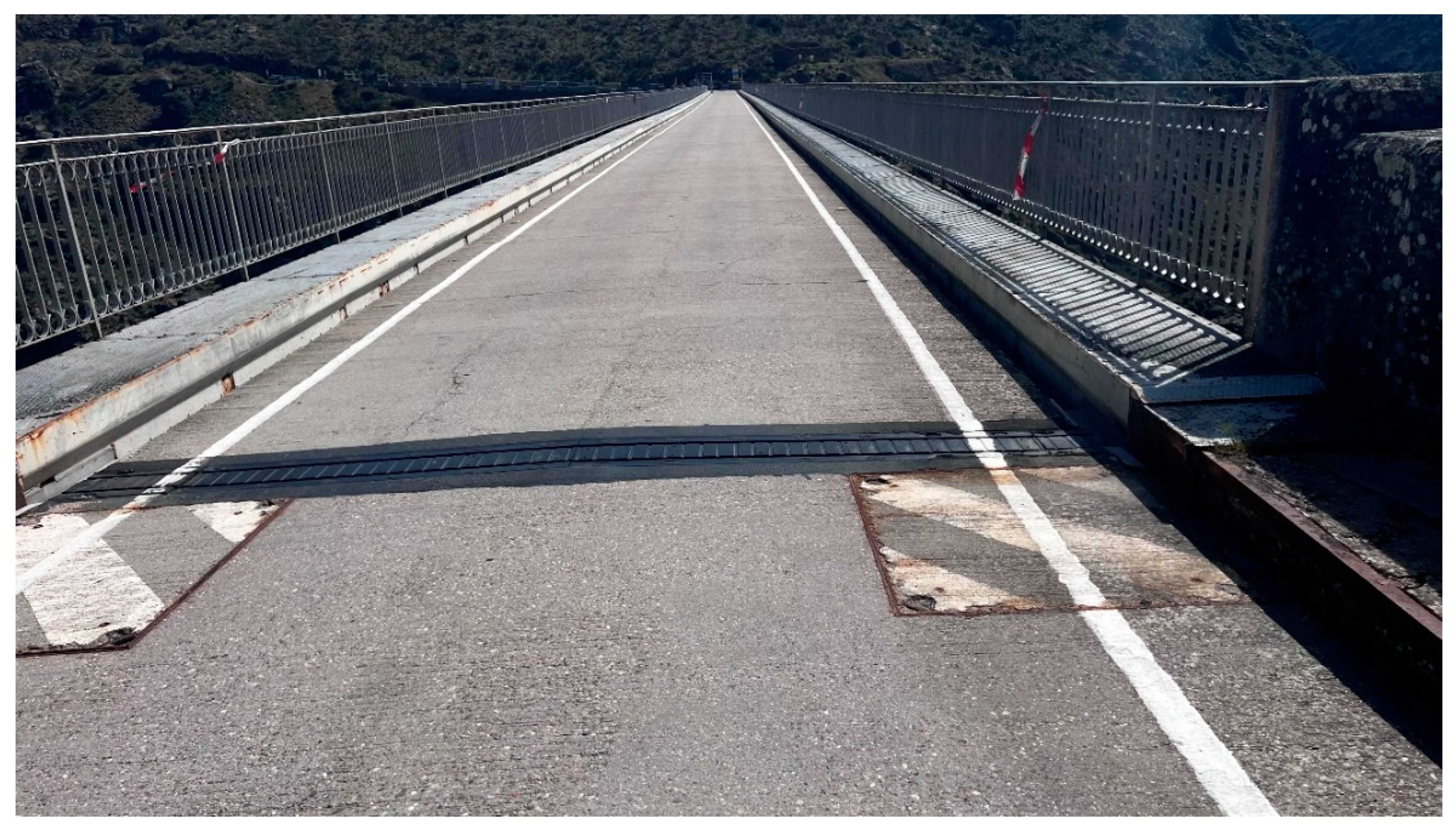
On the platform, corrosion was detected on the railings and walkways (Figure 24), along with localized deformation of the handrails on both railings, caused by the loss or theft of cylindrical stiffeners and, in some cases, the detachment of the crowning curb. Additionally, slight deterioration of the joints due to aging, as well as corrosion of the metal planters on the four access sidewalks to the structure, was observed (Figure 24).
5. Conclusions
The flight of a drone on two different days allowed for the visualization of all the bridge units in sufficient detail to determine the existence and extent of any damage. Thanks to the quality of the camera's zoom, areas of the structure susceptible to deterioration due to corrosion could be observed with high precision and clarity, enabling a detailed analysis of the structure’s condition.
It has already been mentioned that in 2013, an intervention was carried out on the structure, aimed at repairing the main girders of the deck and replacing the existing wearing course with a new, lighter slab. However, no repainting was performed; in fact, the structure had not undergone a complete repainting since 1991. At that time, a three-layer protection system was applied [13].
Considering these precedents, the overall state of conservation of the structure can be regarded as adequate, with no severe deterioration that could, in the short term, affect the bridge’s current functionality.
The bridge exhibits generalized deterioration of the entire anti-corrosion protection system due to aging, with localized corrosion in areas where moisture accumulates. These include the hidden faces of the crossbeams over the abutments, the support areas of the piers on their foundation supports, connections between stringers and crossbeams, and the metal decking of the slab. Corrosion has also been detected in the piers, particularly at the joints between L-shaped profiles and plates, where internal moisture has led to interstitial corrosion, causing profile deformation due to the expansion of corrosion.
Some of the observed corrosion may have originated from leaks in the deck before its repair and replacement in 2013, meaning such issues might not recur. An additional consequence of corrosion is the loss of the head of one of the four anchor bars of the last pier at its downstream end.
Overall, while corrosion is localized, it has not spread over more than 4% of the bridge’s total surface area. This is noteworthy given that the existing anti-corrosion protection system was applied in 1991, more than 30 years ago. This is significant because protective treatments for metallic elements, such as paint-based systems, typically do not exceed a service life of 30 years. Therefore, the inspection has confirmed that now is the appropriate time to renew the protective system.
Although the observed damage does not compromise the current functionality of the structure, the aging of the corrosion protection system and the localized corrosion that has already led to section loss and the failure of some components make it both appropriate and necessary to renew the protection system. This renewal should include repairing and sealing areas where section loss has occurred and replacing the anchor bar of the last pier.
The structure exhibits durability-related issues that are generally present but localized and do not endanger its structural safety under current traffic restrictions (maximum weight limit of 15 tons and a speed limit of 30 km/h).
Based on the observations, it is deemed appropriate to equip the structure with a new protection system that will offer corrosion resistance for at least another 25 years. Before this, localized repairs should be made to the observed defects and deterioration, with particular attention given to cleaning and preparing corroded areas. This will ensure that the new protection system has a proper base, preventing premature failure before reaching its full service life. In other words, both preventive actions to halt the progression of corrosion and remedial actions to repair some metallic elements are proposed. Examples include installing a new anchor bar in Pier 7 and replacing stiffeners in railings.
The inspection results confirm that drones are a highly effective tool for conducting detailed and comprehensive visual observations of both accessible and inaccessible components of large civil metal structures. In the case of the Requejo Bridge, using drones eliminated the need for complex and costly access methods that would have otherwise been essential. Additionally, this methodology aligns with sustainability principles by reducing resource consumption, minimizing material waste, and lowering the environmental impact of traditional inspection methods. By decreasing the use of heavy machinery and auxiliary structures, the carbon footprint of the operation is significantly reduced.
The safety improvements achieved through the use of drones are also noteworthy, as they contribute to workplace well-being and accident prevention—fundamental aspects of sustainable development. The reduced need for risky manual inspections helps safeguard workers’ physical integrity, reinforcing the principles of occupational health and safety.
From an economic perspective, the use of drones enhances cost efficiency by optimizing inspection processes, avoiding unnecessary expenditures on complex access equipment, and allowing for more precise, data-driven maintenance planning. This promotes long-term infrastructure sustainability by extending the lifespan of existing structures and reducing the frequency of major repairs.
The data collected through drones can be used to generate detailed technical reports and provide valuable information for integration into management and monitoring systems for structural conditions. This enables the identification of urgent intervention needs and the periodic monitoring of inspected elements through recurring drone flights. Furthermore, the experience gained from this inspection can be applied to similar tasks, expanding the potential applications of this technology in the field of structural conservation and maintenance.
This study focused exclusively on using drones to inspect a large metal structure of significant heritage value. The images and videos captured by drone cameras can serve multiple purposes beyond structural analysis, functioning as valuable visual documentation.
The integration of additional sensors, such as thermal cameras, could further enhance these inspections by detecting hidden damage or analyzing the origin of surface defects with greater accuracy. In this instance, weather conditions did not allow for thermographic inspections [17,23,24], but their future inclusion could significantly enrich the results.
Finally, it is important to explicitly highlight the relationship of this research with sustainability, occupational safety, and efficiency in infrastructure management. In particular, this work aligns with the following Sustainable Development Goals (SDGs):
- SDG 9 (Industry, Innovation, and Infrastructure): It promotes innovation in infrastructure inspection and maintenance through the use of drones, optimizing resources and extending the lifespan of structures.
- SDG 11 (Sustainable Cities and Communities): It contributes to the preservation of heritage infrastructure and enhances its maintenance in a sustainable manner.
- SDG 12 (Responsible Consumption and Production): It reduces material waste and the need for additional resources through more efficient inspections.
- SDG 13 (Climate Action): It minimizes the carbon footprint by avoiding more polluting traditional methods for infrastructure inspection and maintenance.
- SDG 8 (Decent Work and Economic Growth): It improves occupational safety by reducing the risks associated with manual inspections in hard-to-reach areas.
Funding
This research received no external funding.
Informed Consent Statement
Any research article describing a study involving humans should contain this statement. Please add “Informed consent was obtained from all subjects involved in the study.” OR “Patient consent was waived due to REASON (please provide a detailed justification).” OR “Not applicable.” for studies not involving humans. You might also choose to exclude this statement if the study did not involve humans. Written informed consent for publication must be obtained from participating patients who can be identified (including by the patients themselves). Please state “Written informed consent has been obtained from the patient(s) to publish this paper” if applicable.
Data Availability Statement
We encourage all authors of articles published in MDPI journals to share their research data. In this section, please provide details regarding where data supporting reported results can be found, including links to publicly archived datasets analyzed or generated during the study. Where no new data were created, or where data is unavailable due to privacy or ethical restrictions, a statement is still required. Suggested Data Availability Statements are available in section “MDPI Research Data Policies” at https://www.mdpi.com/ethics.
Acknowledgments
In this section, you can acknowledge any support given which is not covered by the author contribution or funding sections. This may include administrative and technical support, or donations in kind (e.g., materials used for experiments).
Conflicts of Interest
Declare conflicts of interest or state “The authors declare no conflicts of interest.” Authors must identify and declare any personal circumstances or interest that may be perceived as inappropriately influencing the representation or interpretation of reported research results. Any role of the funders in the design of the study; in the collection, analyses or interpretation of data; in the writing of the manuscript; or in the decision to publish the results must be declared in this section. If there is no role, please state “The funders had no role in the design of the study; in the collection, analyses, or interpretation of data; in the writing of the manuscript; or in the decision to publish the results”.
References
- S. Pérez – Fadón Martínez, J. E. Herrero Beneítez, D. Morillo Rocha, and D. Martínez Larrad, “El puente de Ricobayo. El retorno de los arcos,” Cauce 2000 Rev. la Ing. Civ., vol. 71, pp. 36–43, 1995.
- INE, “Alteraciones de los municipios en los Censos de Población desde 1842. Provincia: 49 Zamora, Municipio: 49071 Fonfría,” Instituto Nacional de Estadística (INE). [Online]. Available: https://www.ine.es/intercensal/intercensal.do?search=3&codigoProvincia=49&codigoMunicipio=071&btnBuscarCod=Consultar+selección.
- INE, “Alteraciones de los municipios en los Censos de Población desde 1842. Provincia: 49 Zamora, Municipio: 49065 Fermoselle,” Instituto Nacional de Estadística (INE). [Online]. Available: https://www.ine.es/intercensal/intercensal.do?search=3&codigoProvincia=49&codigoMunicipio=065&btnBuscarCod=Consultar+selección.
- L. A. Hortelano Mínguez, “Patrimonio territorial como activo turístico en la «Raya» de Castilla y León con Portugal,” Cuad. Tur., vol. 36, no. 36, p. 247, 2015. [CrossRef]
- J. I. Martín Benito, Barcas de paso en el Reino de León (De la Edad Med ia al siglo XX). Benavente, Zamora, Spain, 2015.
- P. C. Navarro and T. Abad Balboa, “La construcción del territorio: Caminos y puentes en Castilla y León,” Hist. las Obras Públicas en Castilla y León Ing. Territ. y Patrim., pp. 299–414, 2008.
- J. E. Ribera Dutaste, “Puente-viaducto de Requejo, sobre el Duero, en Pino (Zamora),” Rev. Obras Públicas, vol. LXII, no. 2035, pp. 471–475, 1914, [Online]. Available: https://web.archive.org/web/20110826092622/http://ropdigital.ciccp.es/pdf/publico/1914/1914_tomoI_2035_01.pdf.
- M. Fernández García, “Puente – Viaducto de Requejo,” Rev. Obras Públicas, vol. 62, no. 1, pp. 423–428, 1914, [Online]. Available: https://web.archive.org/web/20160304101422/http://ropdigital.ciccp.es/pdf/publico/1914/1914_tomoI_2031_01.pdf.
- J. R. Millán García, “Liderazgo nacional y caciquismo local: Sagasta y el liberalismo zamorano,” Ayer, pp. 233–259, 2000, [Online]. Available: https://www.jstor.org/stable/41324948.
- J. E. Ribera Dutaste, Estudio sobre los grandes viaductos. 1897. [Online]. Available: http://cataleg.upc.edu/record=b1013973~S1*cat.
- IGME, Mapa Geológico de España. Memoria de la hoja 368 Carbajales de Alba. 1982. [Online]. Available: https://info.igme.es/cartografiadigital/geologica/Magna50Hoja.aspx?intranet=false&id=368.
- Instituto Geológico y Minero de España, Mapa Geotécnico 200k - Hoja 28 (Alcañices). 1976. [Online]. Available: https://info.igme.es/cartografiadigital/tematica/Geotecnico200Hoja.aspx?Id=28&language=es.
- J. A. Llombart Jaques and D. Rodríguez Bragado, “Rehabilitación del puente-viaducto de Requejo (Puente de Pino).,” Rev. Obras Públicas, vol. 162, no. 3562, pp. 93–103, 2015, [Online]. Available: http://search.ebscohost.com/login.aspx?direct=true&db=a9h&AN=101597027&lang=es&site=ehost-live.
- V. García Ortells, “100 elementos del Patrimonio Industrial en España,” Revista de historia industrial. [Online]. Available: https://www.cultura.gob.es/planes-nacionales/planes-nacionales/patrimonio-industrial/actuaciones/elementos-patrimonio-industrial.html.
- C. Cuerno Rejado, “Origen y desarrollo de los Sistemas de Aeronaves Pilotadas por Control Remoto,” in Los Drones y sus aplicaciones a la ingeniería civil, 2015, pp. 15–32. [Online]. Available: https://www.fenercom.com/wp-content/uploads/2015/03/Los-Drones-y-sus-Aplicaciones-a-la-Ingenieria-Civil-fenercom-2015.pdf.
- Y. Li and C. Liu, “Applications of multirotor drone technologies in construction management,” Int. J. Constr. Manag., vol. 19, no. 5, pp. 401–412, 2019. [CrossRef]
- R. Rodríguez Elizalde, “Structural Inspection by RPAS (Drones): Quality Work with Preventive Guarantee,” J. Eng. Appl. Sci. Technol., pp. 1–11, 2022. [CrossRef]
- R. Rodríguez Elizalde, “Use of RPAS (DRONES) for Masonry Arch Bridges Inspection: Quality and Sustainable Work with Preventive Guarantee,” Rev. Gestão Soc. E Ambient., vol. 18, no. 12, 2024. [CrossRef]
- J. Seo, L. Duque, and J. Wacker, “Drone-enabled bridge inspection methodology and application,” Autom. Constr., vol. 94, pp. 112–126, 2018. [CrossRef]
- M. Oñate de Mora, “Tipología de aeronaves pilotadas por control remoto,” in Los drones y sus aplicaciones a la ingeniería, vol. 1, 2015, pp. 49–56. [Online]. Available: https://www.fenercom.com/wp-content/uploads/2015/03/Los-Drones-y-sus-Aplicaciones-a-la-Ingenieria-Civil-fenercom-2015.pdf.
- T. Elijah, R. S. Jamisola, Z. Tjiparuro, and M. Namoshe, “A review on control and maneuvering of cooperative fixed-wing drones,” Int. J. Dyn. Control, vol. 9, no. 3, pp. 1332–1349, 2021. [CrossRef]
- L. V. Nguyen, T. H. Le, I. Torres Herrera, N. M. Kwok, and Q. P. Ha, “Intelligent path planning for civil infrastructure inspection with multi-rotor aerial vehicles,” Constr. Robot., vol. 8, no. 2, 2024. [CrossRef]
- R. Rodríguez Elizalde, “Assessment of Architectural Heritage and Historic Structures Through Aerial Thermography,” Rev. Gestão Soc. E Ambient., vol. 18, no. 10, 2024. [CrossRef]
- R. Rodríguez Elizalde, “Comprehensive Technical Inspection of a Medieval Bridge (Ponte de Vilanova, in Allariz) Using Microtechnological Tools,” Eng, vol. 5, no. 4, pp. 3259–3283, 2024. [CrossRef]
Figure 1.
Location of the Requejo Bridge on the National Topographic Map published by the Spanish National Geographic Institute.
Figure 1.
Location of the Requejo Bridge on the National Topographic Map published by the Spanish National Geographic Institute.
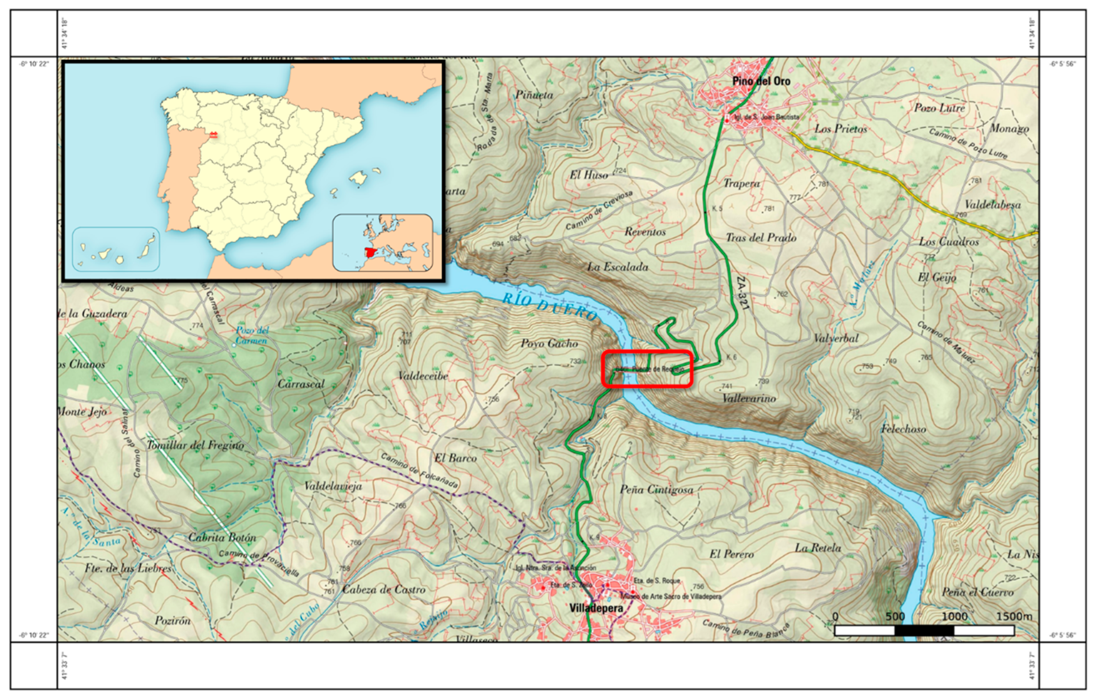
Figure 2.
General view of the Requejo Bridge, downstream elevation (photograph by the author).
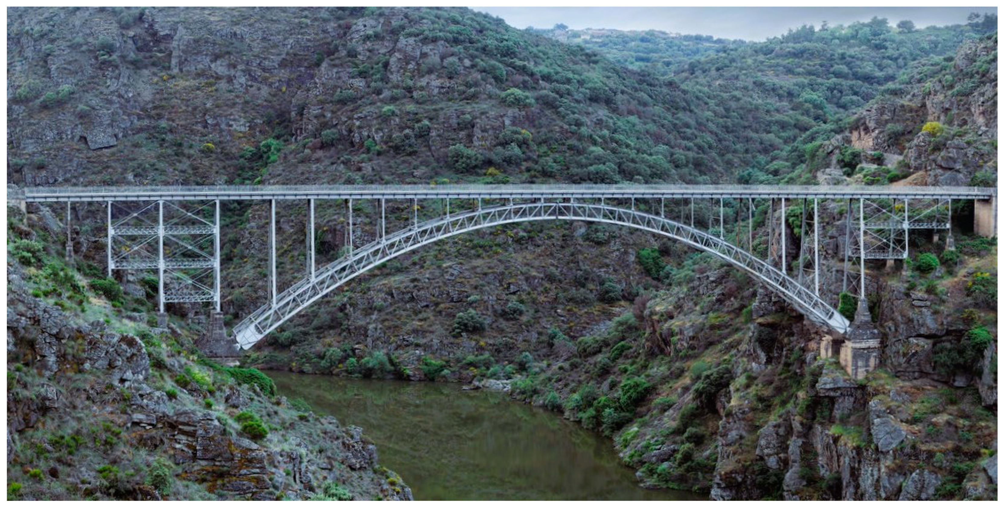
Figure 3.
Location of the Requejo Bridge on an aerial orthophotograph produced by the Spanish National Geographic Institute.
Figure 3.
Location of the Requejo Bridge on an aerial orthophotograph produced by the Spanish National Geographic Institute.
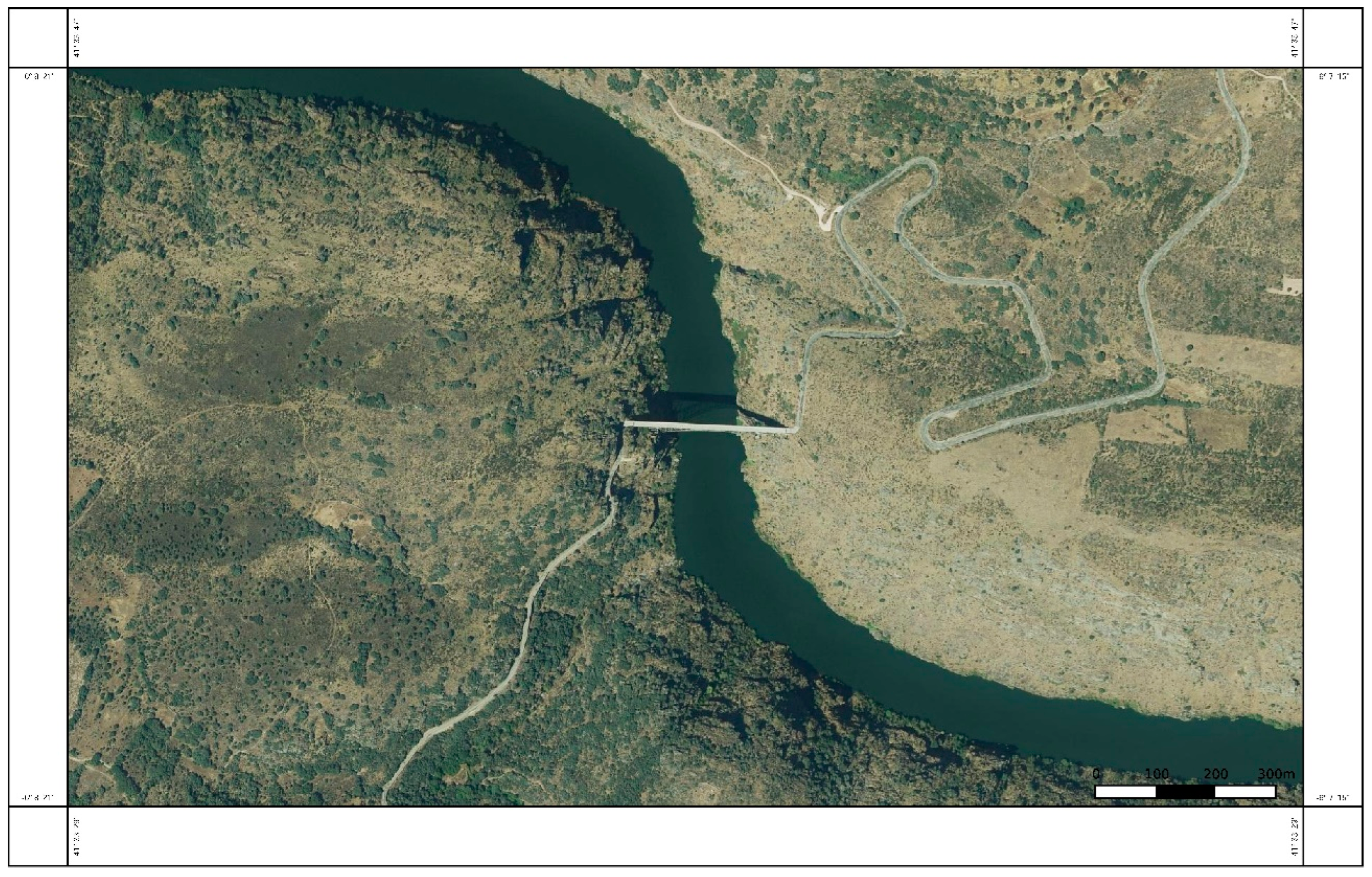
Figure 4.
Elevation of the Requejo Bridge, based on the project by engineer José Eugenio Ribera Dutaste [7].
Figure 4.
Elevation of the Requejo Bridge, based on the project by engineer José Eugenio Ribera Dutaste [7].
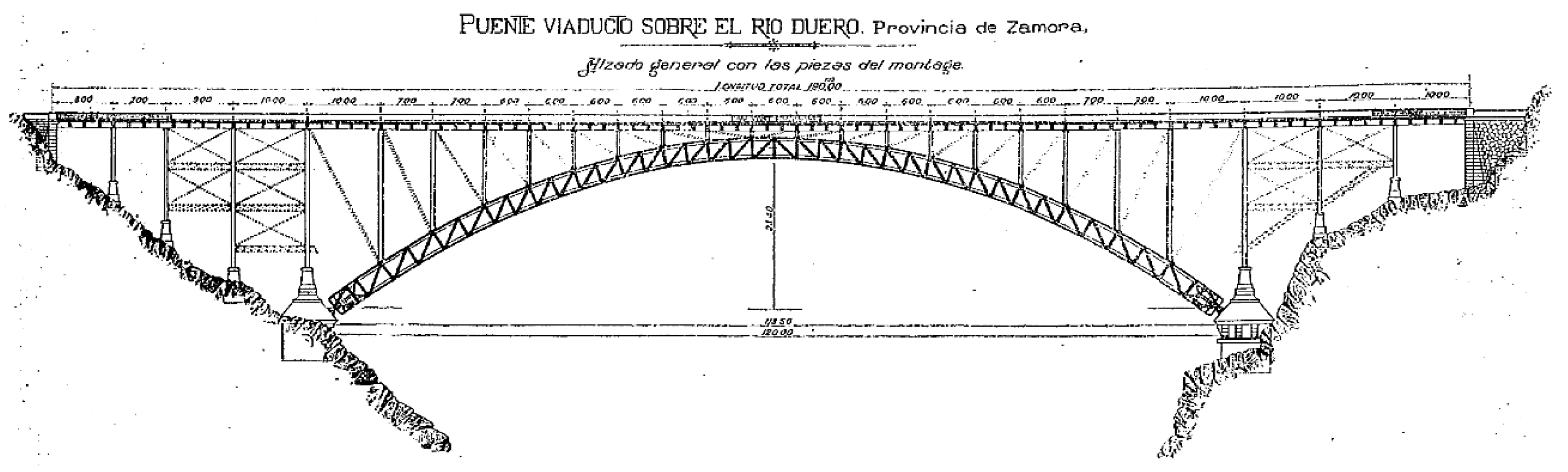
Figure 5.
Graphical calculation of the cantilever assembly of the Requejo Bridge [8].
Figure 5.
Graphical calculation of the cantilever assembly of the Requejo Bridge [8].
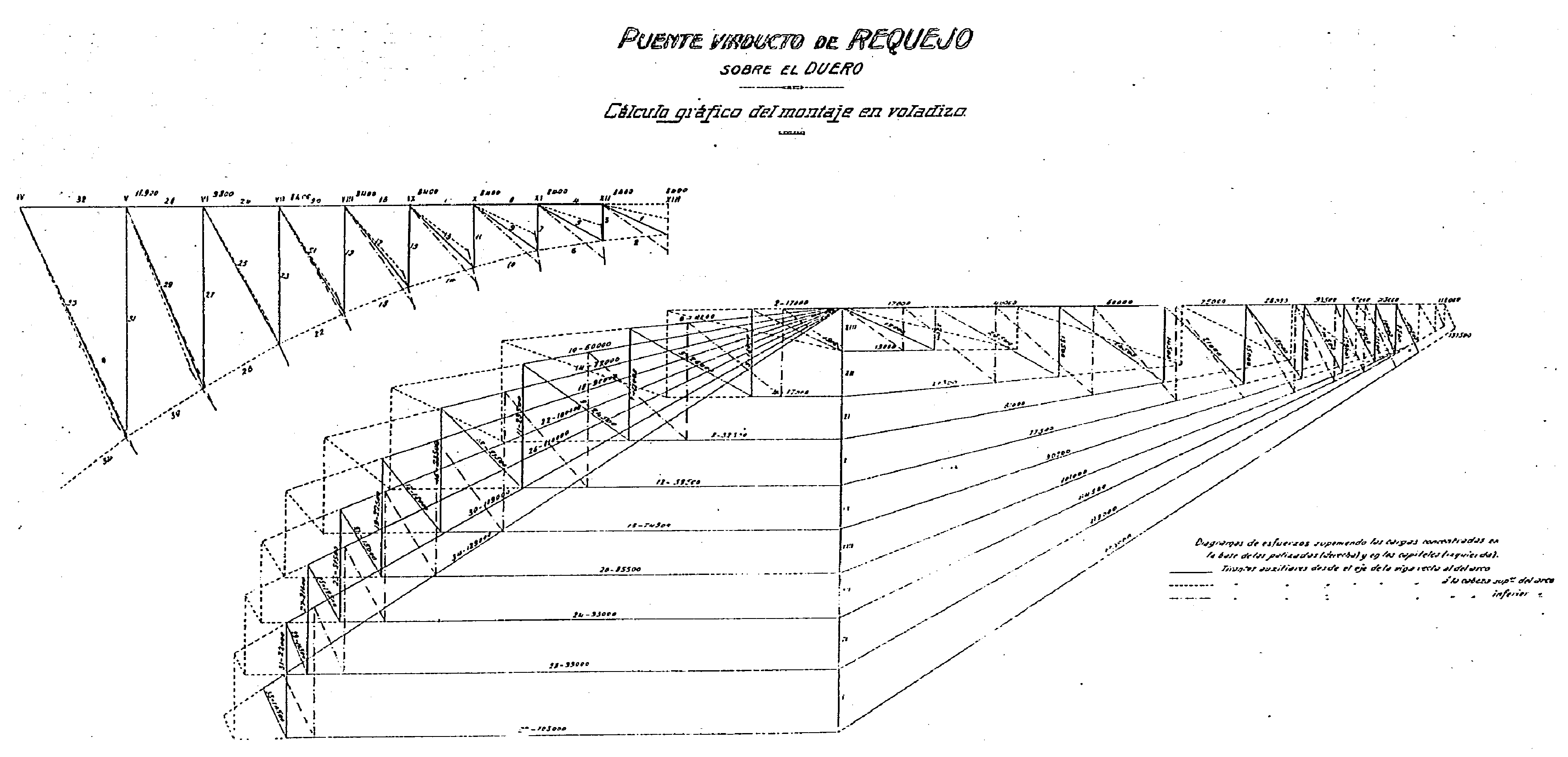
Figure 6.
Geological framework legend, geological map, and cross-section marking the bridge’s location (Source: Geological Sheet 343, 1:50,000 scale, [11]).
Figure 6.
Geological framework legend, geological map, and cross-section marking the bridge’s location (Source: Geological Sheet 343, 1:50,000 scale, [11]).
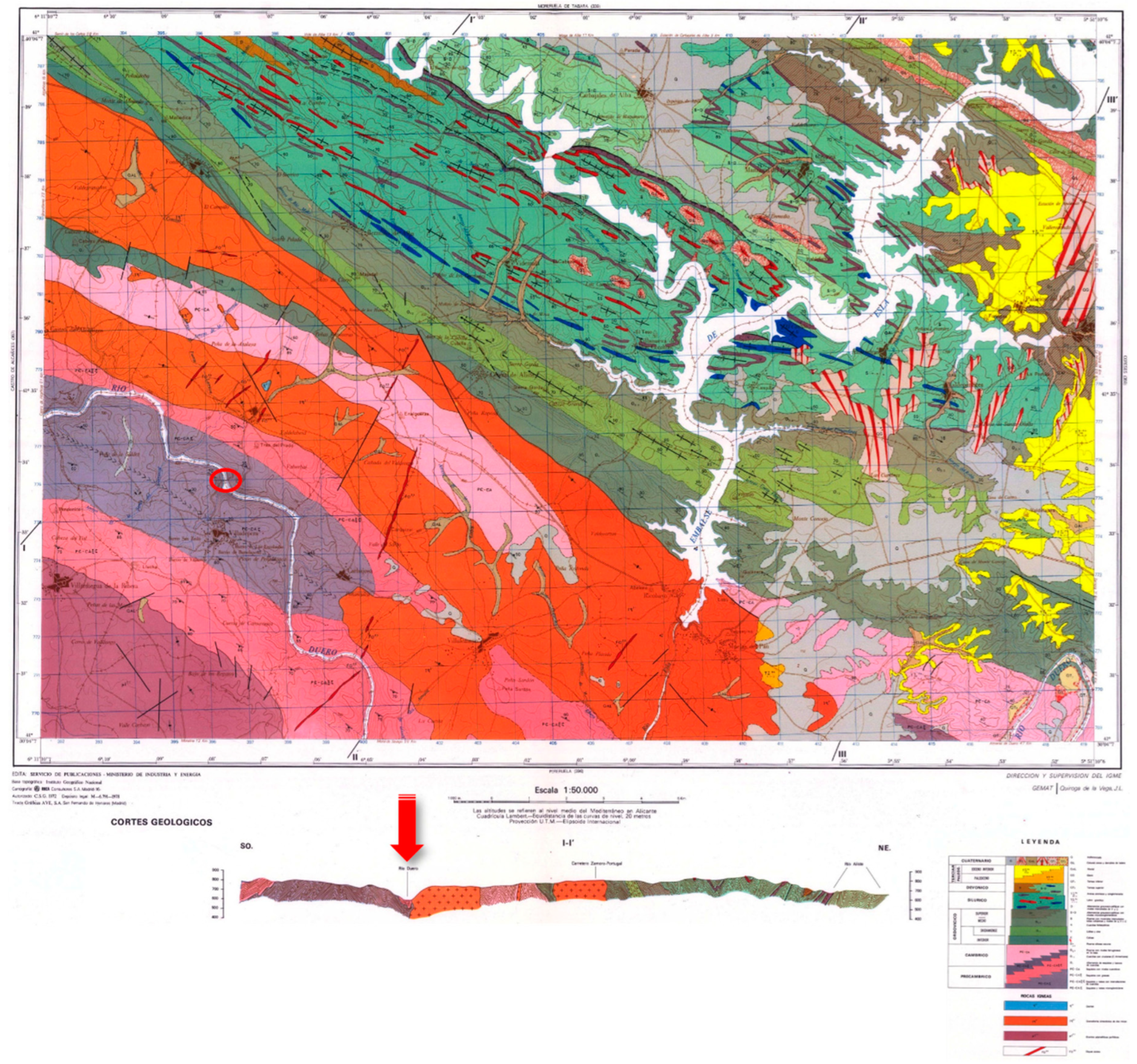
Figure 7.
Partial view of the bridge from the southern side (upstream side), showing the main arch and, in the background, the second abutment with its corresponding support trestles (photograph by the author, taken with a drone).
Figure 7.
Partial view of the bridge from the southern side (upstream side), showing the main arch and, in the background, the second abutment with its corresponding support trestles (photograph by the author, taken with a drone).
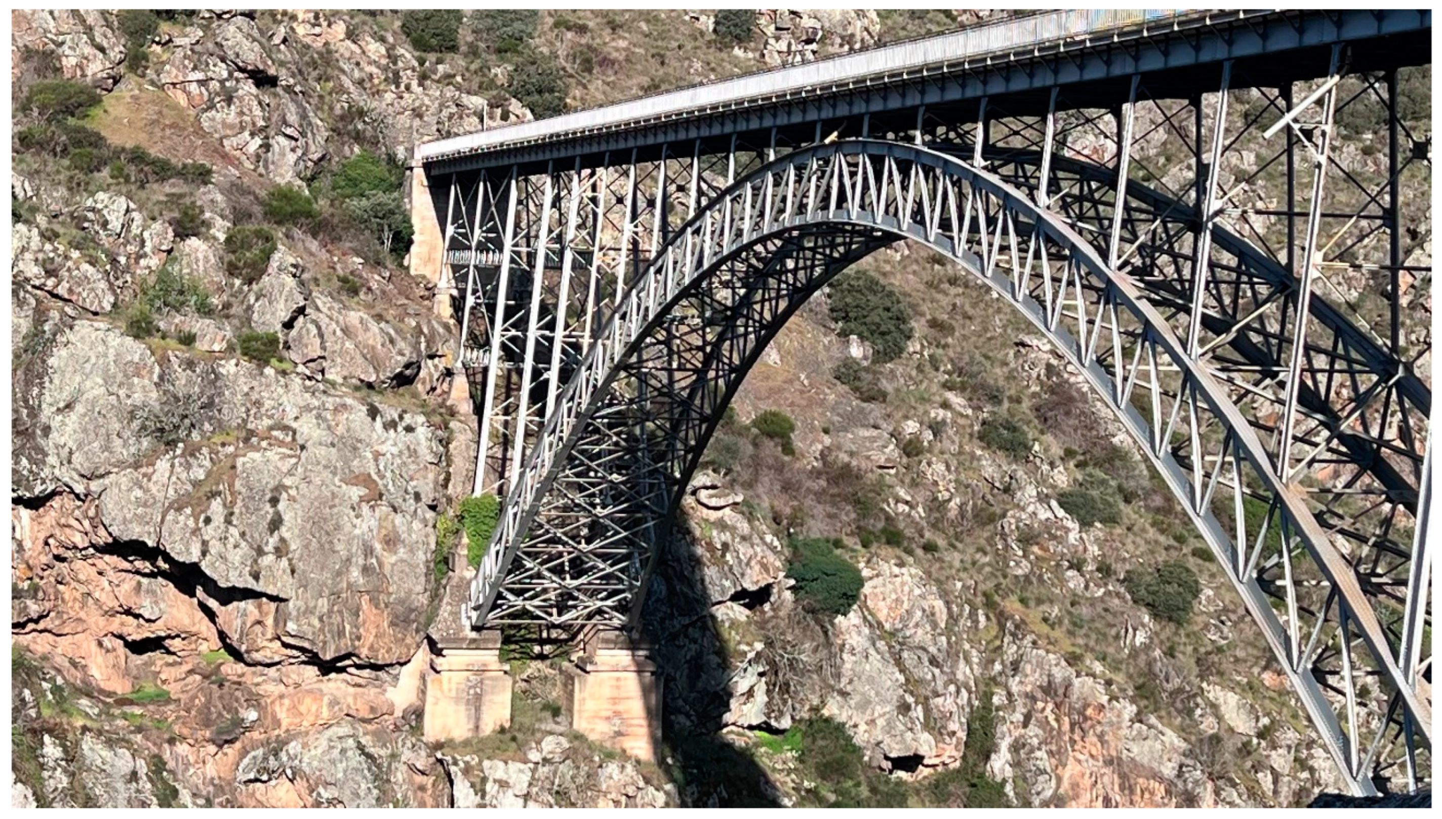
Figure 8.
Arch supports on direct concrete foundations near the second abutment (photograph by the author, taken with a drone).
Figure 8.
Arch supports on direct concrete foundations near the second abutment (photograph by the author, taken with a drone).
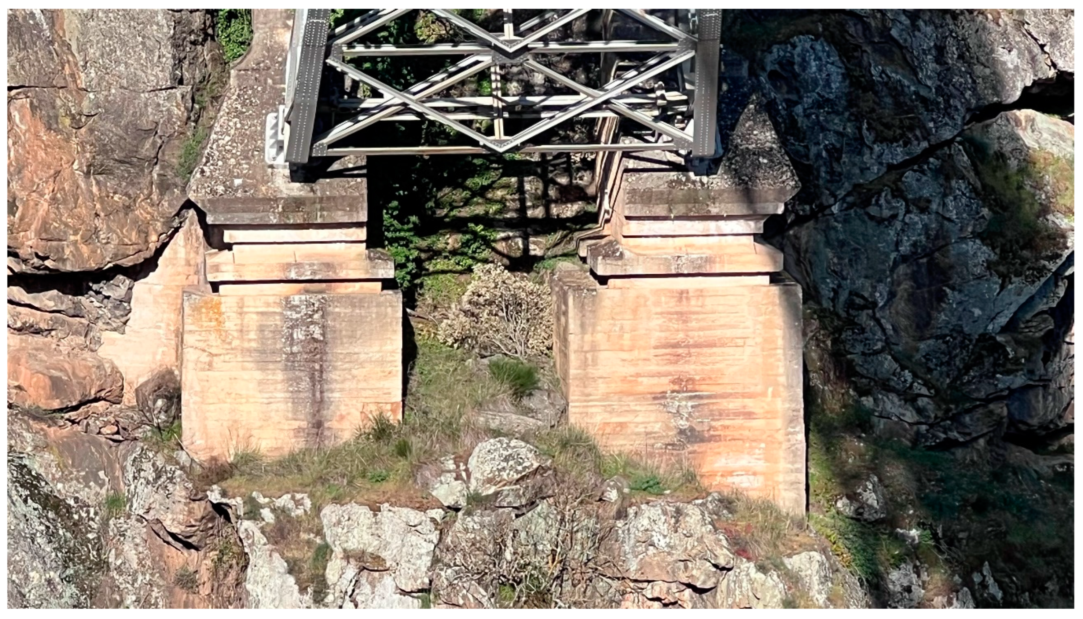
Figure 9.
Examples of upright supports on the arch, using gusset plates fastened with bolts, on the upstream side (photograph by the author, taken with a drone).
Figure 9.
Examples of upright supports on the arch, using gusset plates fastened with bolts, on the upstream side (photograph by the author, taken with a drone).
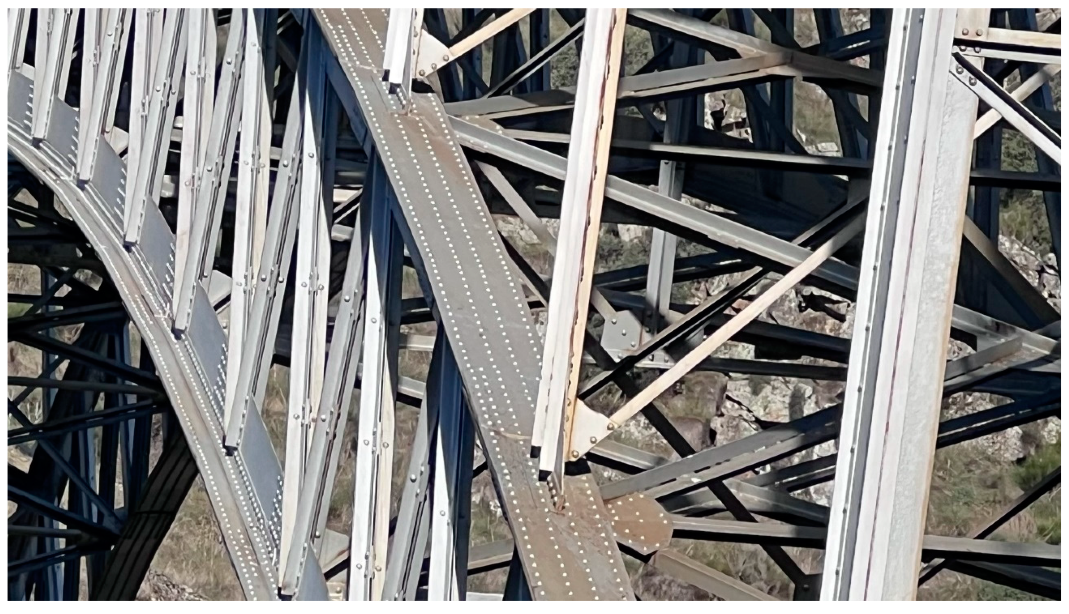
Figure 10.
Cross-section of the Requejo Bridge, corresponding to the design developed by engineer José Eugenio Ribera Dutaste (Ribera Dutaste, 1914).
Figure 10.
Cross-section of the Requejo Bridge, corresponding to the design developed by engineer José Eugenio Ribera Dutaste (Ribera Dutaste, 1914).
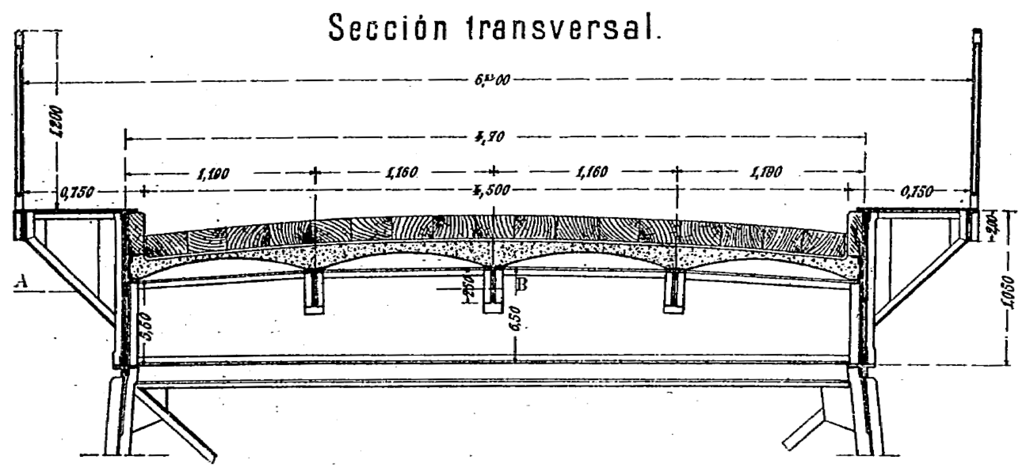
Figure 11.
Multirotor drone approaching the Requejo Bridge to inspect the trestles of the second abutment from the upstream side (photograph by the author).
Figure 11.
Multirotor drone approaching the Requejo Bridge to inspect the trestles of the second abutment from the upstream side (photograph by the author).
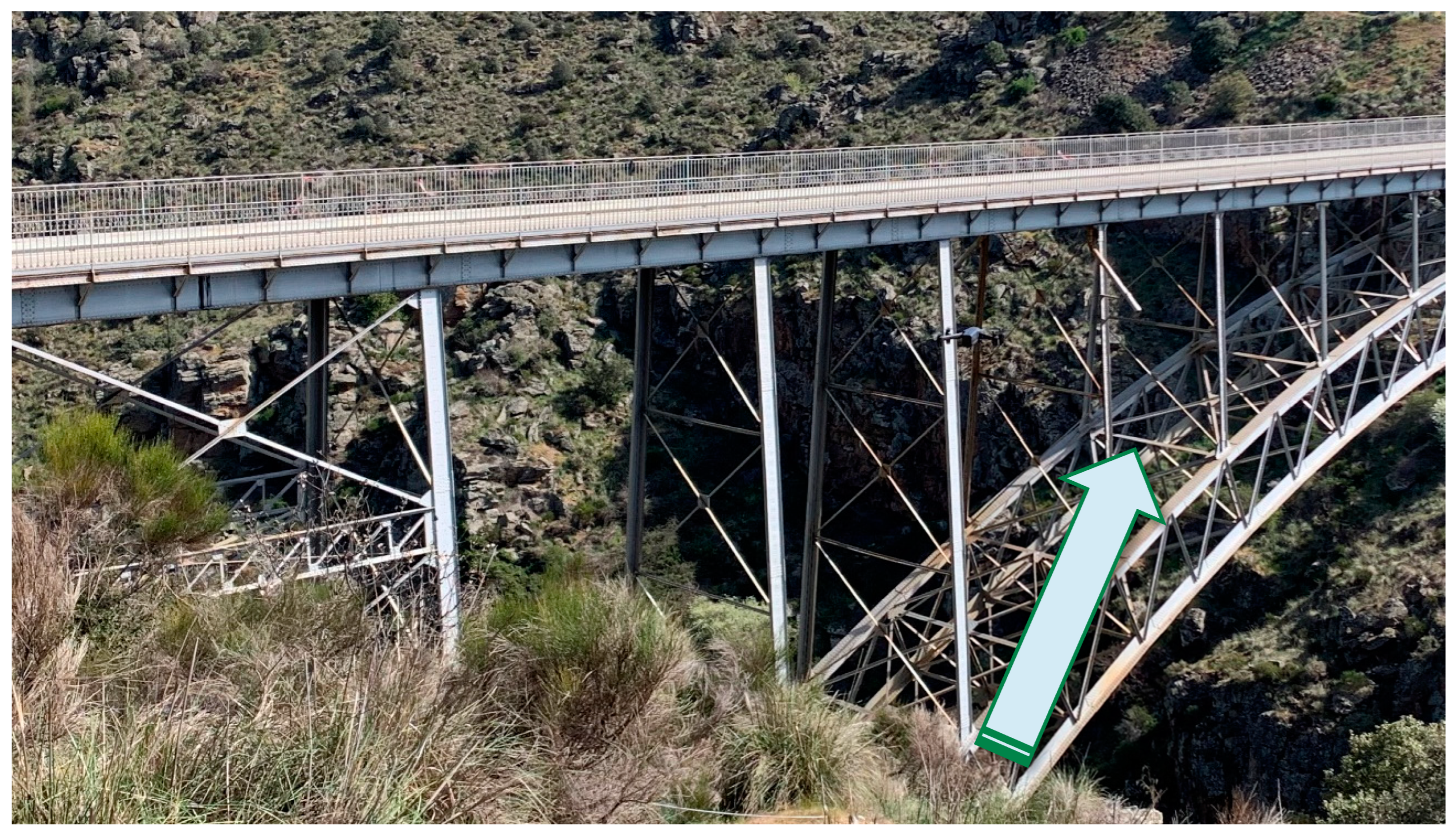
Figure 12.
Wall of the second abutment with runoff water traces (photograph by the author, taken with a drone).
Figure 12.
Wall of the second abutment with runoff water traces (photograph by the author, taken with a drone).
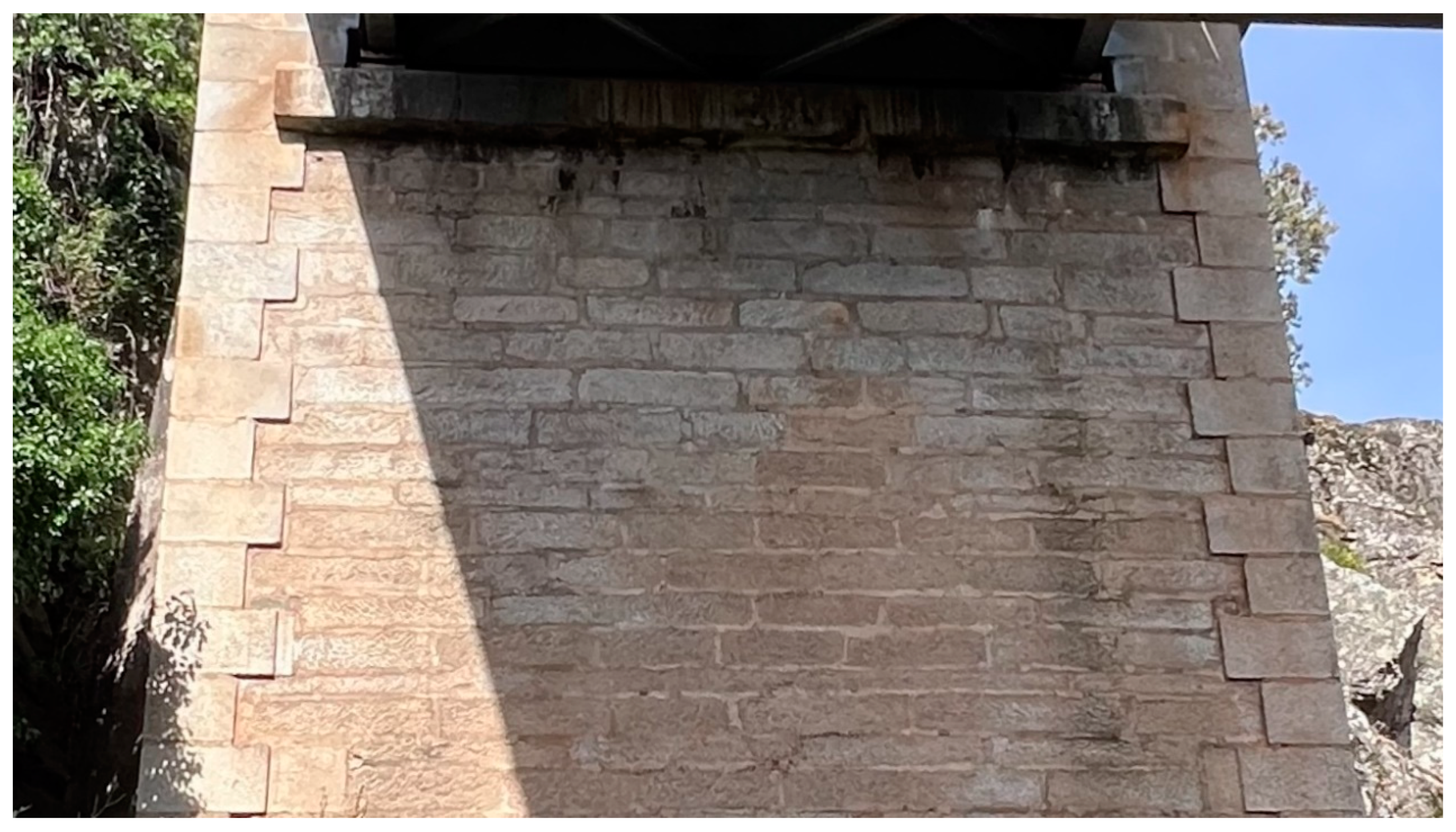
Figure 13.
Presence of organic matter and vegetation on the concrete footing of sheet pile wall 6, downstream side (photograph by the author, taken with a drone).
Figure 13.
Presence of organic matter and vegetation on the concrete footing of sheet pile wall 6, downstream side (photograph by the author, taken with a drone).
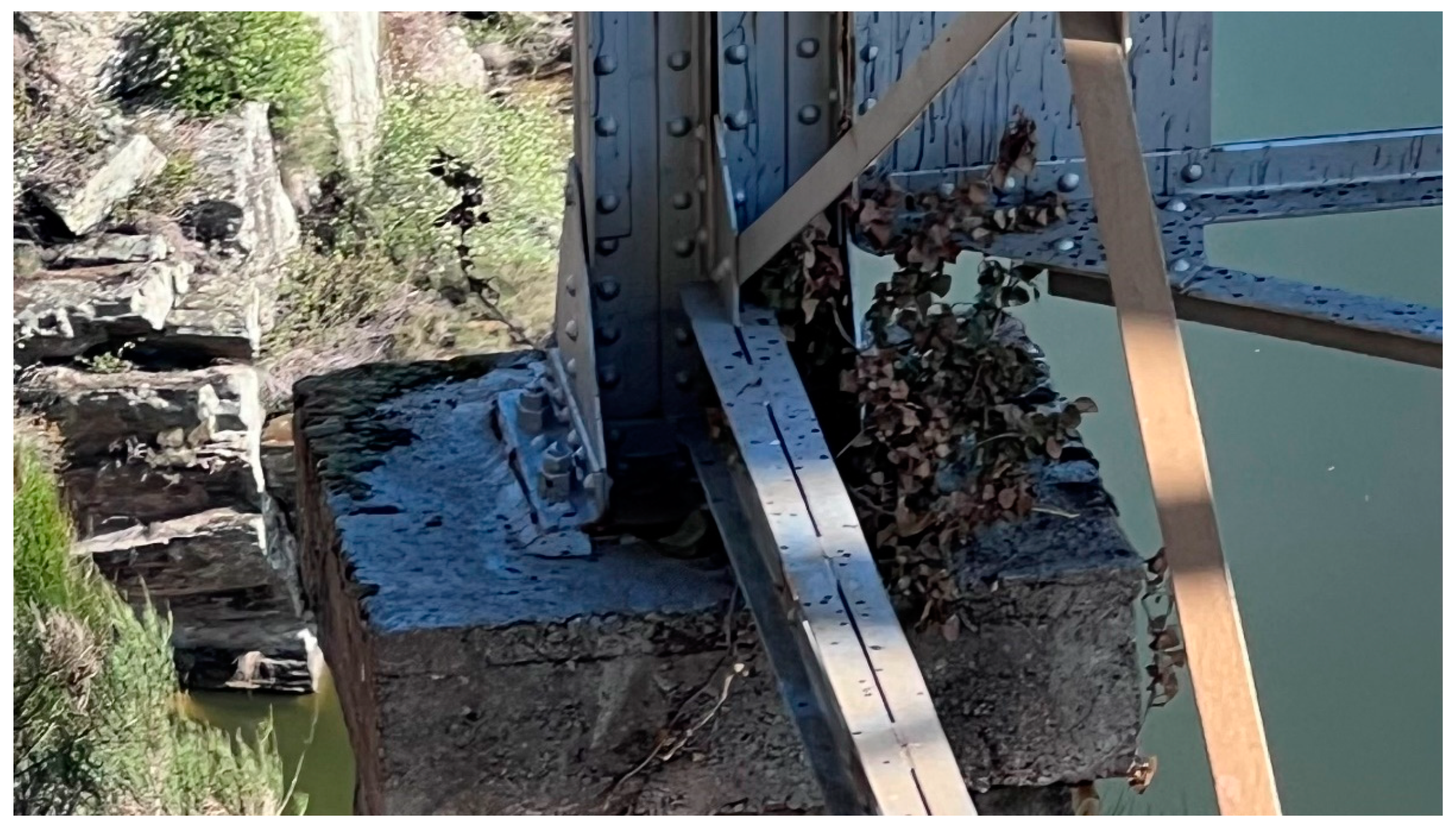
Figure 14.
Corrosion on sheet pile wall number 7, the one closest to the second abutment, downstream side (photograph by the author, taken with a drone).
Figure 14.
Corrosion on sheet pile wall number 7, the one closest to the second abutment, downstream side (photograph by the author, taken with a drone).
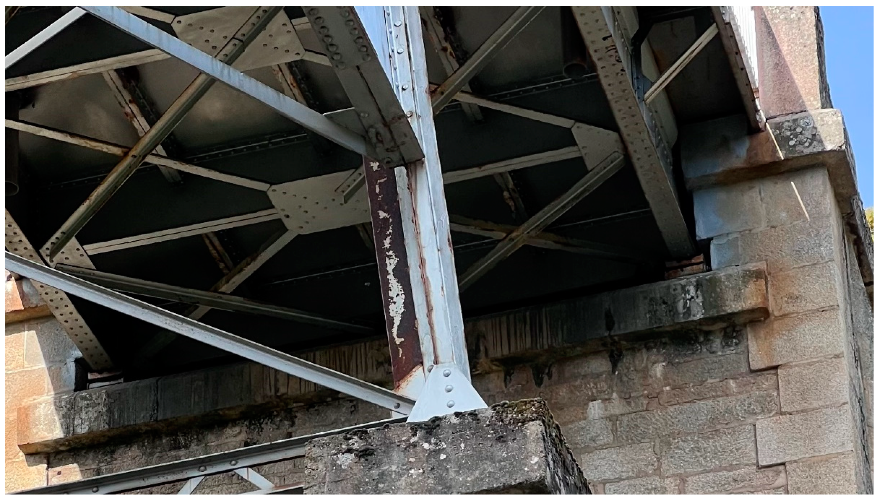
Figure 15.
Loss of an anchor head on sheet pile wall 7, downstream side (photograph by the author, taken with a drone).
Figure 15.
Loss of an anchor head on sheet pile wall 7, downstream side (photograph by the author, taken with a drone).
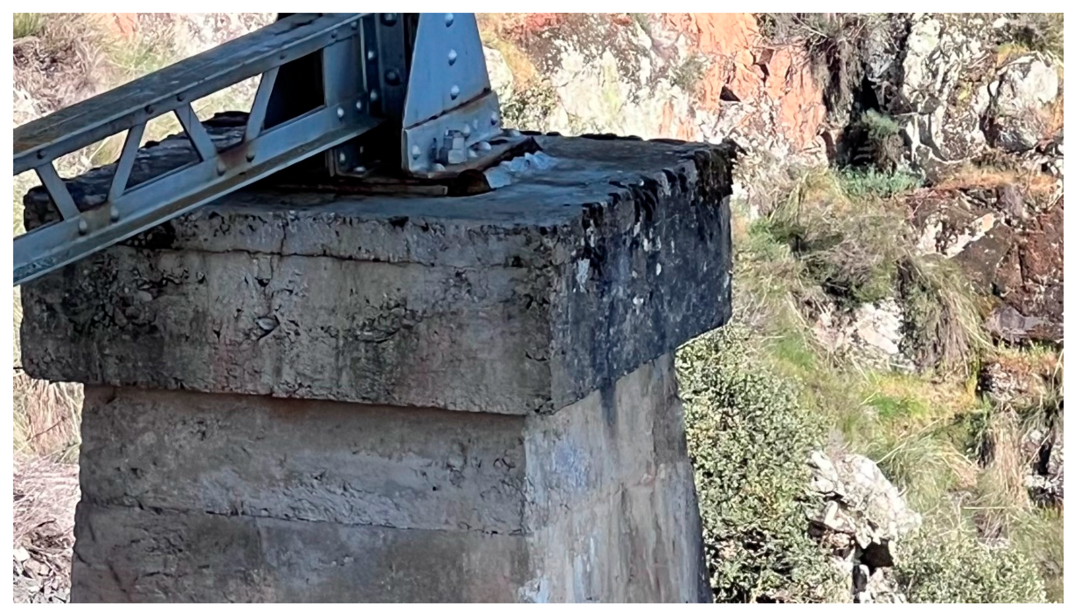
Figure 16.
Localized corrosion on one of the braces of the sheet pile walls at the western end of the bridge, upstream side (photograph by the author, taken with a drone).
Figure 16.
Localized corrosion on one of the braces of the sheet pile walls at the western end of the bridge, upstream side (photograph by the author, taken with a drone).
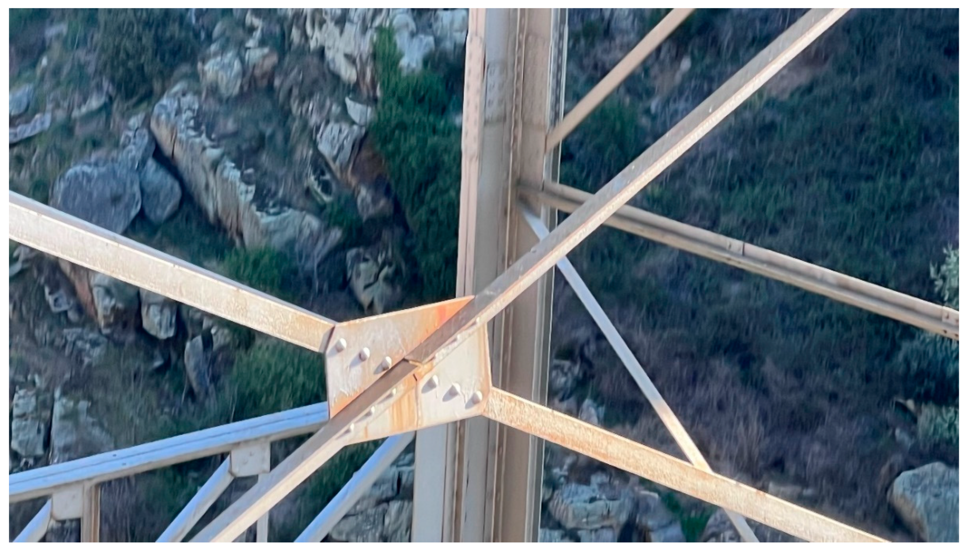
Figure 17.
Bottom view of the arch from the downstream side (photograph by the author, taken with a drone).
Figure 17.
Bottom view of the arch from the downstream side (photograph by the author, taken with a drone).
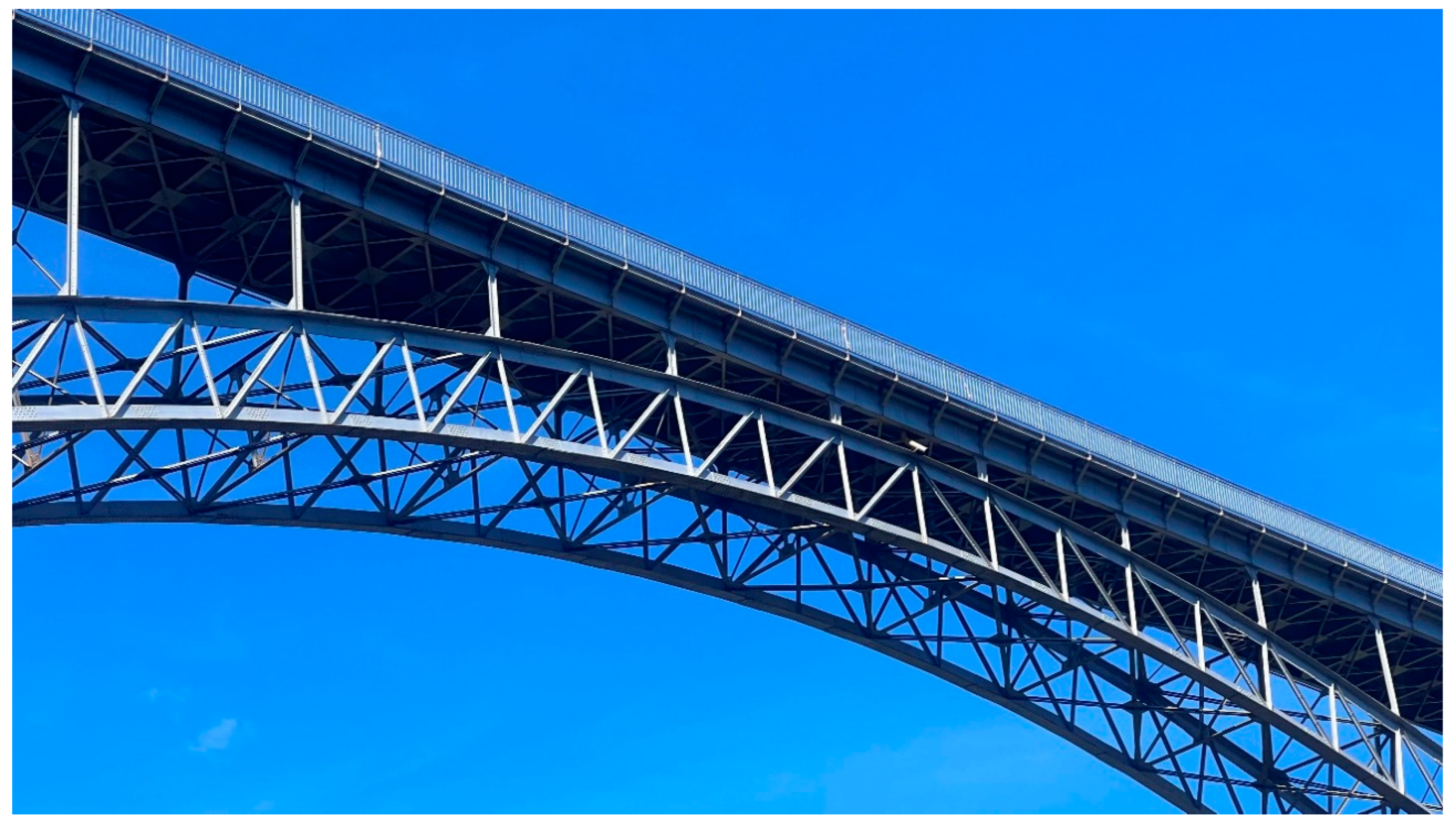
Figure 18.
General state of the arch, in a section between support uprights (photograph by the author, taken with a drone).
Figure 18.
General state of the arch, in a section between support uprights (photograph by the author, taken with a drone).
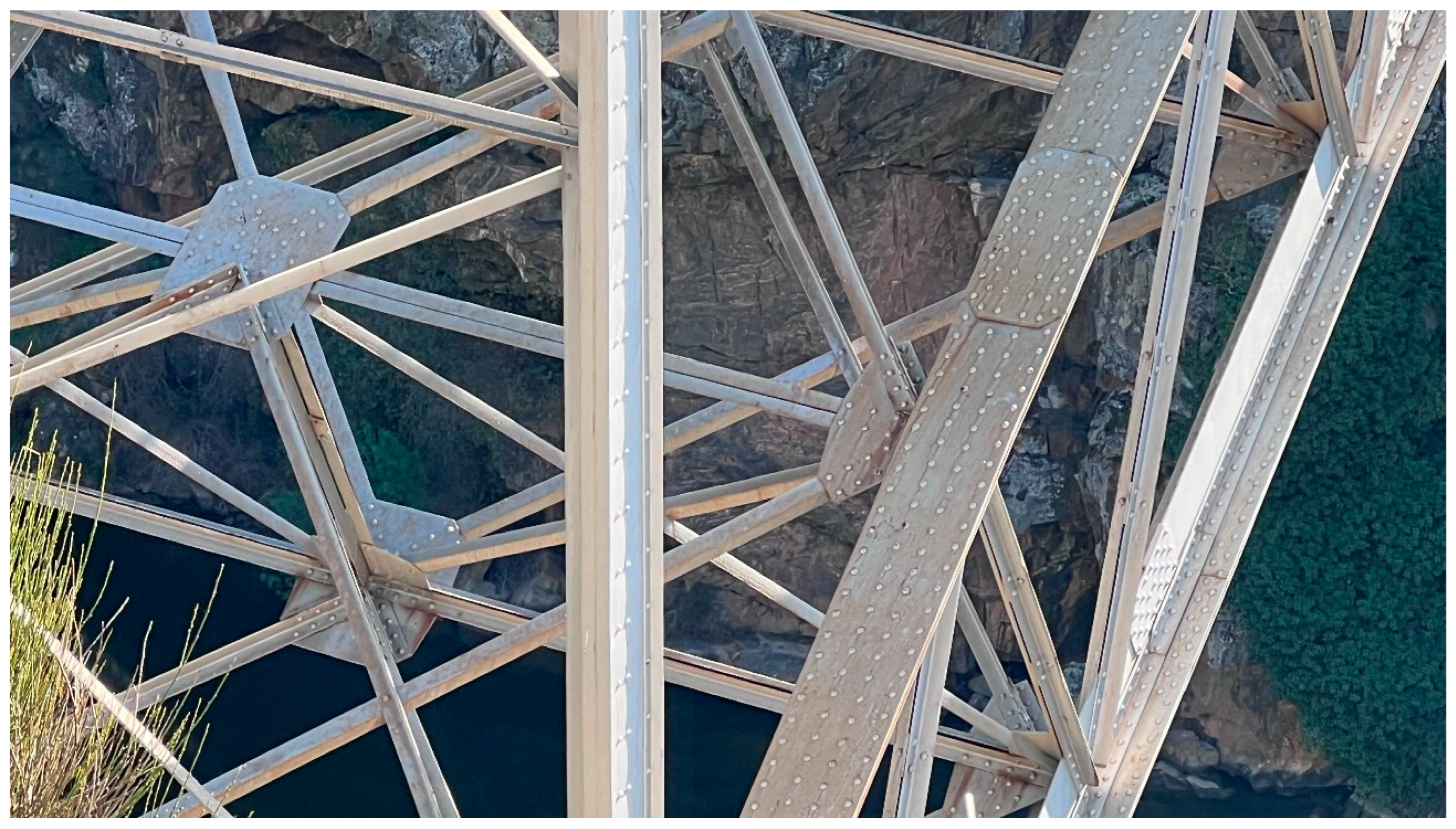
Figure 19.
Detailed view of an arch section with localized corrosion at connection points (photograph by the author, taken with a drone).
Figure 19.
Detailed view of an arch section with localized corrosion at connection points (photograph by the author, taken with a drone).
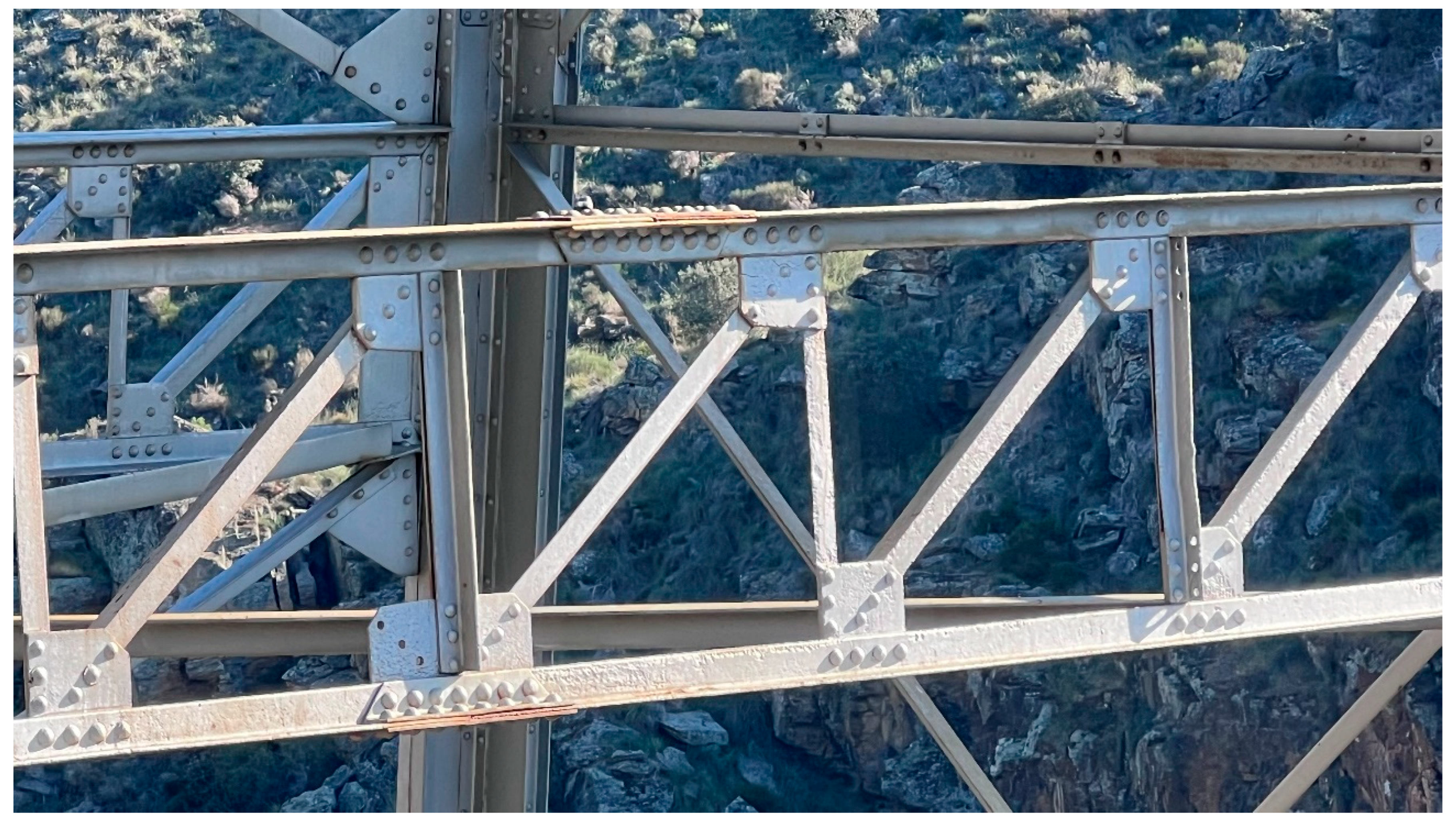
Figure 20.
Detail of corrosion on one of the uprights over the arch (photograph by the author, taken with a drone).
Figure 20.
Detail of corrosion on one of the uprights over the arch (photograph by the author, taken with a drone).
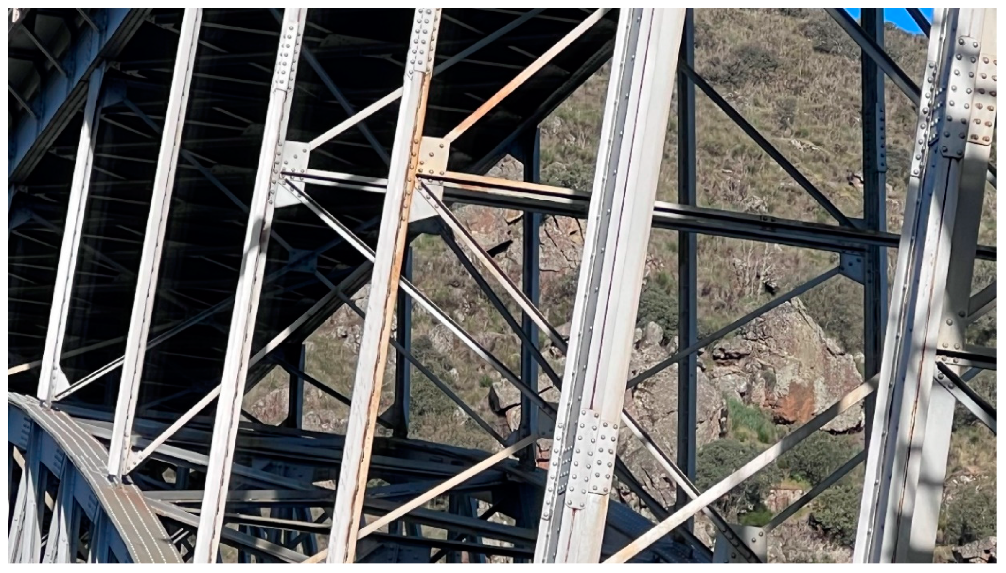
Figure 21.
Bottom view of a deck section, showing numerous elements with localized corrosion symptoms (photograph by the author, taken with a drone).
Figure 21.
Bottom view of a deck section, showing numerous elements with localized corrosion symptoms (photograph by the author, taken with a drone).
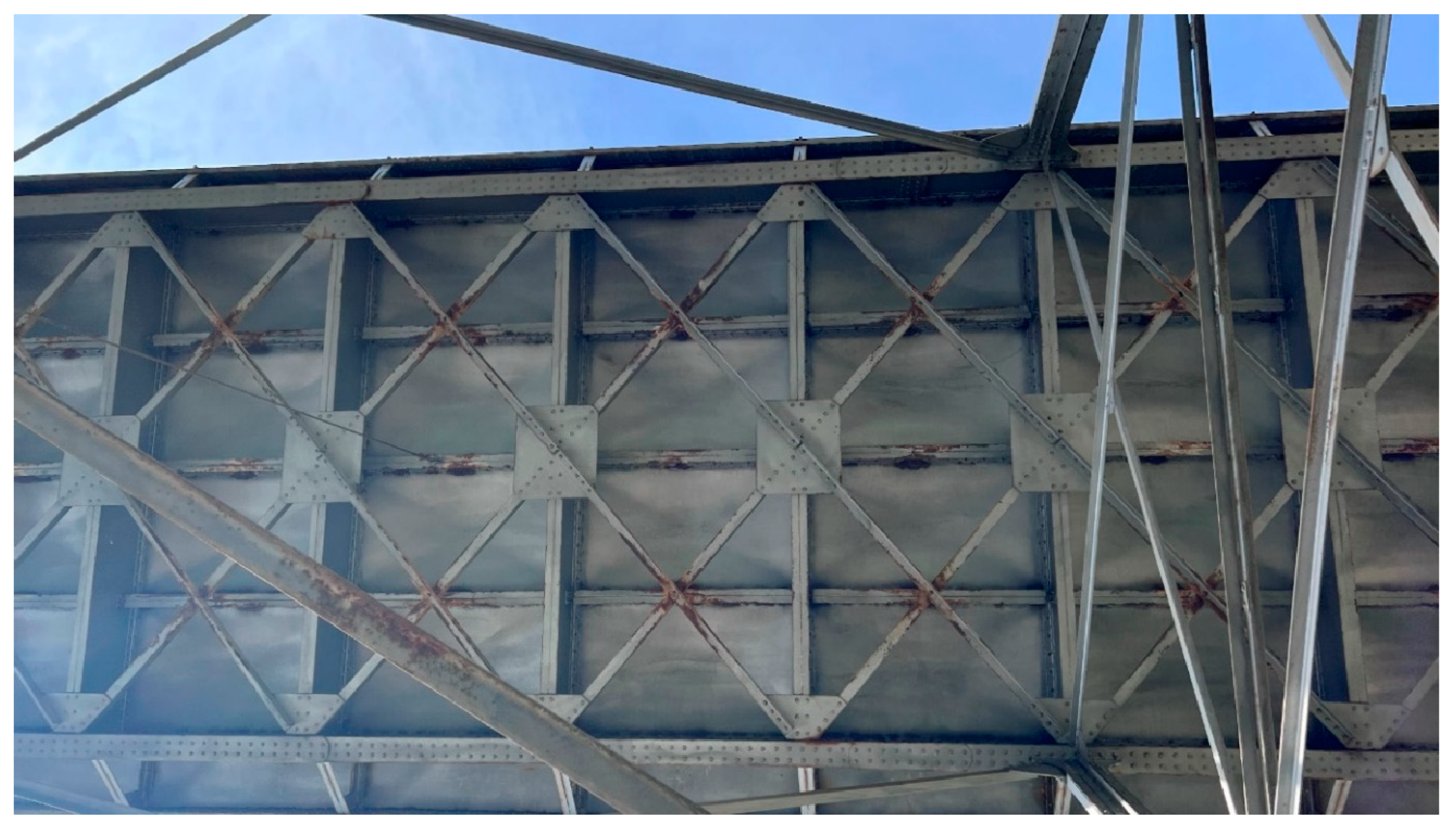
Figure 22.
Detailed view of a deck section with localized corrosion on several elements (photograph by the author, taken with a drone).
Figure 22.
Detailed view of a deck section with localized corrosion on several elements (photograph by the author, taken with a drone).
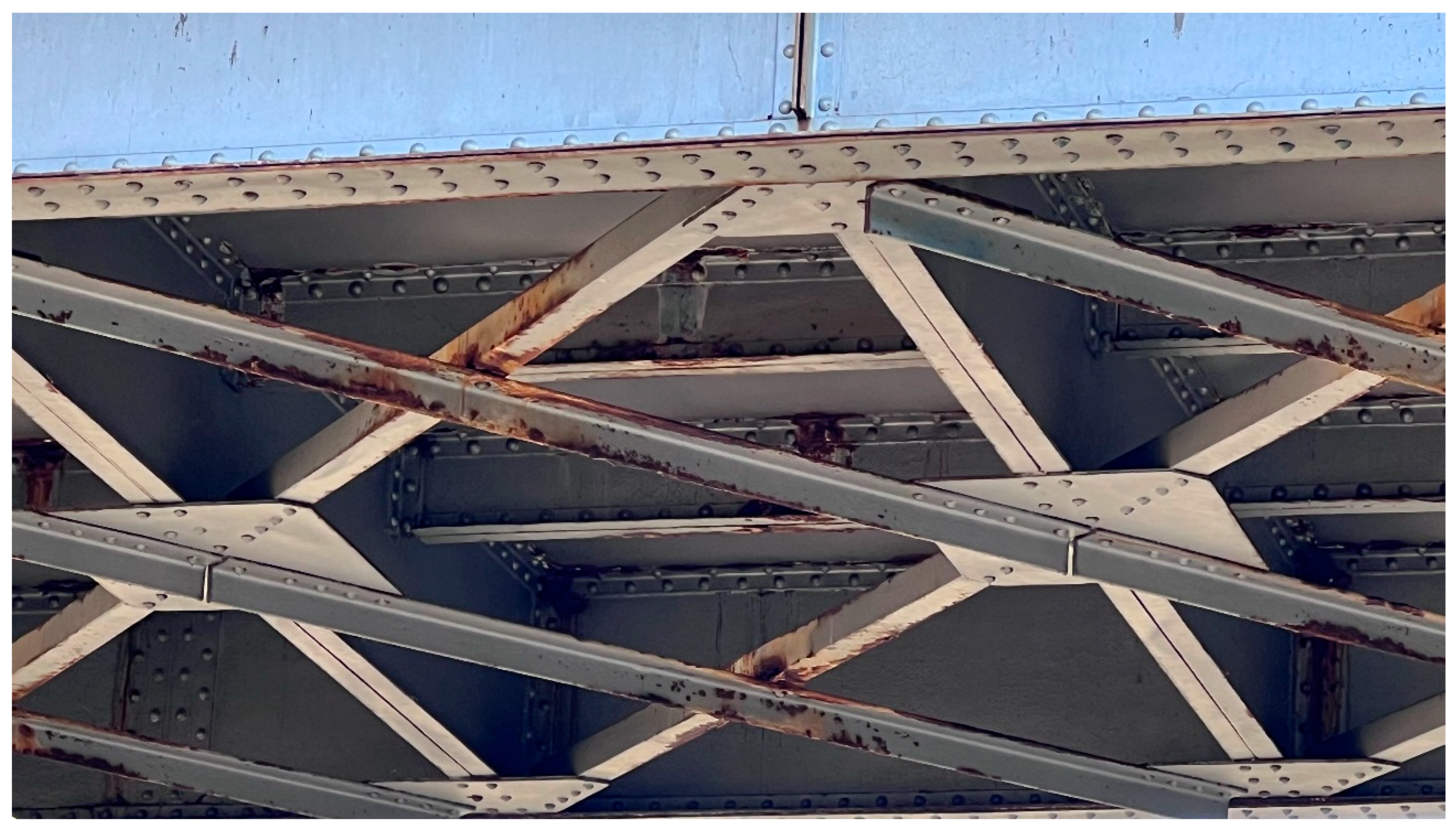
Figure 23.
View of the cornice and the underside of the perimeter protective railing (photograph by the author, taken with a drone).
Figure 23.
View of the cornice and the underside of the perimeter protective railing (photograph by the author, taken with a drone).
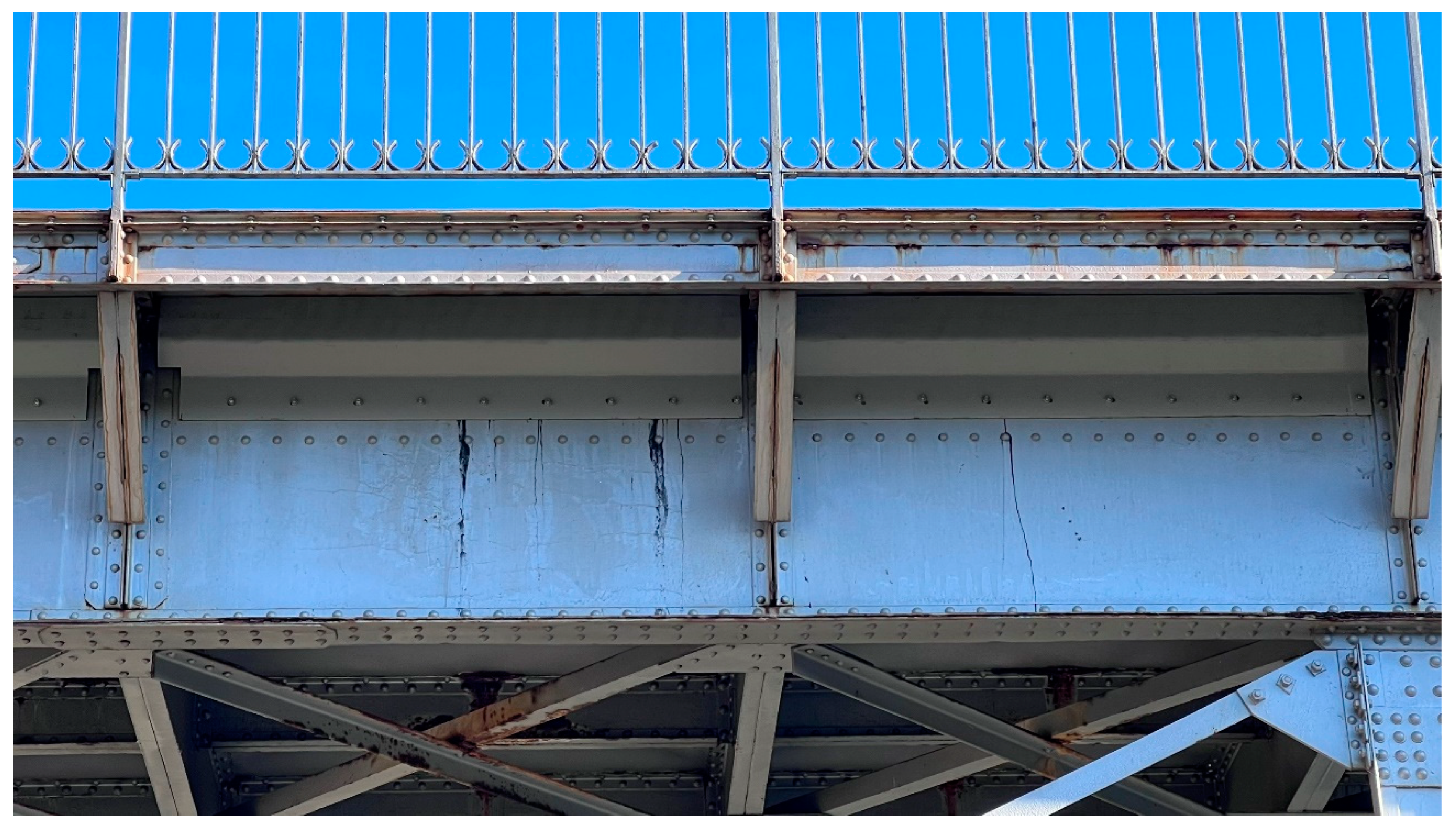
Figure 24.
View of the road platform above, taken from the second abutment (photograph by the author, taken with a drone).
Figure 24.
View of the road platform above, taken from the second abutment (photograph by the author, taken with a drone).
Disclaimer/Publisher’s Note: The statements, opinions and data contained in all publications are solely those of the individual author(s) and contributor(s) and not of MDPI and/or the editor(s). MDPI and/or the editor(s) disclaim responsibility for any injury to people or property resulting from any ideas, methods, instructions or products referred to in the content. |
© 2025 by the authors. Licensee MDPI, Basel, Switzerland. This article is an open access article distributed under the terms and conditions of the Creative Commons Attribution (CC BY) license (http://creativecommons.org/licenses/by/4.0/).
Copyright: This open access article is published under a Creative Commons CC BY 4.0 license, which permit the free download, distribution, and reuse, provided that the author and preprint are cited in any reuse.


