
Submitted:
02 March 2025
Posted:
03 March 2025
You are already at the latest version
Abstract
This study is intended to investigate the impact of adjusting wing dihedral on the aircraft's stability and maneuverability, drawing upon computational fluid dynamics (CFD) simulations and existing aerodynamic theory. We analyzе thе tradе-offs bеtwееn stability and agility at diffеrеnt opеrational rеgimеs, proposing optimal dihеdral for spеcific flight scеnarios. Our findings will open thе way for еnhancing thе K-8/JL-8's pеrformancе and adaptability in divеrsе opеrational еnvironmеnts.
Keywords:
Stability
; Dihedral
; CFD
; flight
1. Introduction
The K-8/JL-8, a mainstay in several air forces globally, thrives on its balanced blend of maneuverability and stability. These crucial flight characteristics are significantly influenced by the dihedral angle of the wings. While empirical data exists, a comprehensive understanding of the interplay between dihedral and its impact across different flight regimes remains elusive. Dihedral angle refers to the upward inclination of an aircraft’s wings relative to the horizontal plane. When wings have dihedral and they form a slight “V” shape. Positive dihedral (wings angled upwards) tends to create a more uniform lift distribution across the wingspan.
Asymmetric airflow due to roll or gusts causes one wing to experience higher lift than the other. Positive dihedral helps counteract this by inducing a rolling moment that tends to level the wings.This balanced lift distribution enhances overall stability during flight. Roll stability refers to an aircraft’s ability to return to level flight after a disturbance (such as a roll). Positive dihedral contributes to roll stability:When the aircraft rolls and the higher wing generates more lift and causing a restoring moment that tends to bring the wings back to level. Positive dihedral reduces the adverse effects of induced drag during turns. The upward angled wings help minimize the drag caused by wingtip vortices. Moderate dihedral angles improve the lift drag ratio and enhancing overall aerodynamic efficiency.
This paper will fills this gap by employing CFD simulations and established aerodynamic principles to explore the intricate changing of dihedral and stabilizer angle in the K-8/JL-8.
2. Motivation
K-8 Aircraft is a jet trainer aircraft, being extensively used in Pakistan Air Force. This study reflects the effect on stability and performance parameters with required suggestions for design optimization. The study is an initial step towards designing of an aircraft, hence this effort will be useful for predicting the stability of an aircraft and also preliminary designing of an aircraft. Our research can inform modifications to the K 8/JL 8 and leading to better handling characteristics for specific training maneuvers. This could translate to smoother flight experiences for student pilots and enhancing their learning and confidence. Our research can contribute to a more comprehensive understanding of the intricate relationship between dihedral angle and its impact on aircraft performance across various flight regimes. This can be valuable for both academic researchers and students interested in aircraft design and aerodynamics.
3. Literature Review
Among all the performance criteria, aeroplane having stability is the most important. If an aircraft meets specific requirements for stability and it is said to be stable. There are two more types of stability: dynamic and static.
The body’s initial reaction to any disturbance is known as static stability. Three types of static stability exist for aircraft: lateral,directional and longitudinal stability.
In the yawing axis, directional stability is defined as follows: [1]
The requirement states that the yawing moment plotted against the side slip angle must have a zero slope in order for the aircraft to remain stable in this specific axis. To minimise the side slip angle and return to the trim conditions and the aircraft would therefore follow the direction of the sidewind.
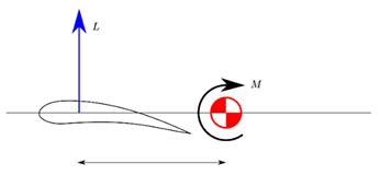
The stability that an aeroplane maintains along its lateral or rolling axis is known as longitudinal stability. Longitudinal stability is depends upon two factors.[1]
When the coefficient of moment is plotted against the angle of attack alpha and it indicates a negative slope when:
This means that in order to resist the disturbance an’ maintain stability and the aircraft must pitch down in response to each wind gust or other disturbance that forces it to pitch upward. Second and the reason for this condition is because our wings are typically positively cambered and meanin’ that even at zero angle of attack and they produce a finite amount of lift. The second requirement is:
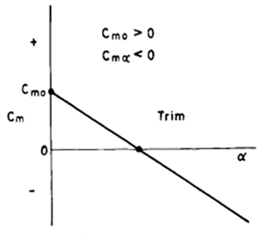
It indicates that even when the aeroplane is flying at zero alpha and it will still generate some moment.
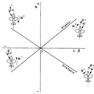
The aircraft’s capacity to maintain stability along its longitudinal axis is known as lateral stability.The prerequisite for lateral stability:[2]
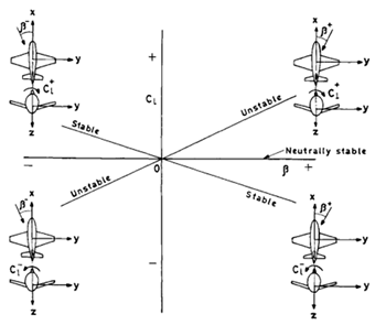
The requirement states that the rolling moment’s slope must be negative when plotted against the side slip angle Beta. All that would happen is that the plane would roll in the opposite direction from the disturbance or gust.
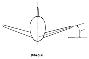
Dihedral
The dihedral angle is one of the primary elements that contributes to lateral stability. is the angle formed by the wind’s plane and the aircraft’s transverse or lateral axis; it is specified as dihedral. If the tips of the wings are pointing upward and it is considered positive; if they are pointing downward and it is considered negative.
On the basis of the dihedral angle allows, after a gust of wind that lowers one wing, this will be submitted to the action of air at a higher angle of attack, increasing its lift as the wing in place more have a high loss of support, generating a scrolling movement which enables the levelling of the wings and therefore its lateral stability [3].
The mentioned characteristics are more frequently observed in low wing aircraft with medium and positive dihedral settings. Negative dihedrals are not advised in particularly low wing aircraft and since these are inherently unstable and further jeopardise the flight and resulting in the aircraft’s lack of lateral stability. Conversely and with high wing aircraft and dihedral is typically not necessary; nevertheless and in the event that the aircraft is overly stable and the negative dihedral may serve to mitigate this occurrence.
With respect to the negative dihedral configuration states that when the arrangement of forces is inverted, and when the plane suffers a disturbance, the force generates a torque which increases the scrolling, making unstable plane, but rolls easily [4].
Initially people might not understand the reason for adding instability to an aeroplane project. But for instance,building an aircraft requiring quick response and good mobility such as that of warplanes or particular aircraft models is seen to have several beneficial applications.
Determining the dihedral angle should also be done carefully because the aircraft needs a certain amount of instability to be controlled and manoeuvred. A small dihedral angle might make it difficult for the aircraft to withstand shocks while in flight and prevent the wings from staying level. However and a very high angle of the wings increases the likelihood of remaining capped and which makes it more challenging for the pilot to execute manoeuvres required for this gap.
In short, “if the dihedral is little, there is not enough self-level, and much, steering effort increases too much, compromising manoeuvrability.” [1].
Dihedral Effect
Dihedral effect is the amount of roll moment produced per degree (or radian) of sideship. The magnitude of dihedral effect contributed by vertical position of the wing is large and may necessitate a noticeable dihedral angle for the low wing configuration [5].
Dihedral helps keep the aircraft stable during turns. It prevents excessive rolling and helps maintain level flight.
Pamadi [1] wrote that wing with dihedral angle has a stabilizing effect on the aircraft. The lower wing will encounter a relative airflow to a greater angle of attack, producing an increase in lift, while the wing has a higher reduction of its support generating a roll moment. This moment makes that the plane has its wings levelled to return to its original position.
Now, there is small discussion how diherdral angle of wing effect Lift to Drag ratio. Dihedral reduces the overall lift generated by the wing.The increased dihedral angle leads to additional drag.Moderate dihedral strikes a balance between stability and efficiency.
Very large dihedral (or anhedral) may waste lift, making the overall aircraft less efficient.
At extreme angles (e.g., 45 degrees from level), the wing would need to produce lift equal to 1.4 times the aircraft’s weight, affecting efficiency.
However, at low angles, the impact on efficiency is minimal compared to handling and stability benefits.
For a best Aerodynamic effeciency of an aircraft,there must be balance between stability and perfomance parameters.
4. Brainstorming
Reasons for choosing JL-8/K-8 as case study:
- It is a trainer Jet aircarft having less complexity than modern aircraft.
- Simple structure and Geometry of aircarft allows us to make simple changes.
- It is still in production.
- Not much study is done on this aircraft
- It will open a gateway for understanding stabiltiy and aerodynamic characteristics of much complex aircrafts.
5. METHODOLOGY
A concise methodology adopted for out findings is as under:
- We conduct an extensive review of existin’ literature on static stability in aircraft design.
- Investigation how wing dihedral affects both longitudinal and lateral stability.
- Exploration the connection between wing dihedral and aerodynamic efficiency.
- Developing a 3D body of the K 8/JL 8 aircraft using XFRL5 software.
- Performing stability simulations using XFRL5.
- We relate the stability analysis results to established theoretical concepts.
- Computing the lift coefficient (CL) and drag coefficient (CD) for various flight conditions.
- We create a detailed CAD model of the K 8/JL 8 based on 2D drawings.
- Simulating airflow around the CAD model using CFD software.
- Comparing CL/CD ratios obtained from stability analysis and CFD.
- Investigating how small variations in dihedral angle impact stability.
- Summarize the relationship between wing dihedral and stability.
- Acknowledge any limitations in the study and suggest areas for further research.
- Recap the main findings regarding dihedral and stability and emphasizing practical relevance for aircraft designers.

5.1. Aircraft Data
Data of K-8/JL-8 provided by the manufacturer is as under [7]:
Dimensions:
| Overall Length | 11.6 m |
| Overall height | 4.21 m |
| Wing area | 17.02 m2 |
| Wing span | 9.63 m |
| length Wheel track | 2.54 m |
| Wheel base | 4.442 m |
Weights:
| Normal take-off weight | 3700 kg |
| Useful load | 943 kg |
| Internal fuel capacity | 780 kg |
| Weight empty | 2757 kg |
| Maximum take-off weight | 4332 kg |
Flight Performance:
| Maximum level Speed | 800 km/hr |
| Rate of climb at sea level | 30 m/s |
| Service ceiling | 13600 m |
| Built-in Range | 1560 km |
| Ferry range (with drop tanks | 2140 km |
Airfoil data:
| Wing tip | NACA 64-A-114 |
| Wing root | NACA-64-A-212 |
| Vertical tail | NACA-64-A-012 |
5.2. Aircraft Data
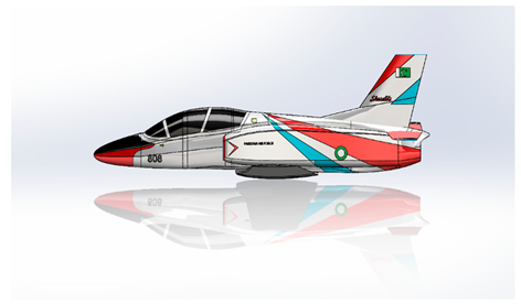
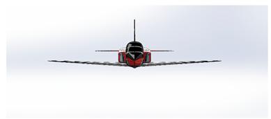
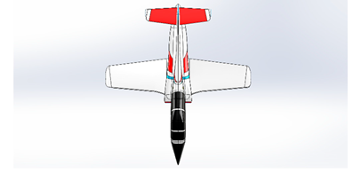
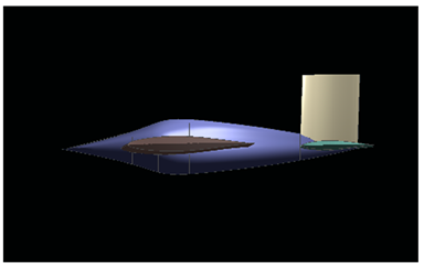
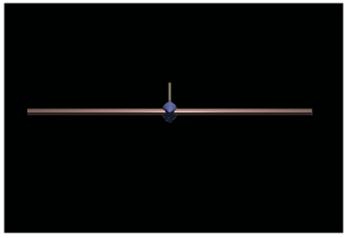
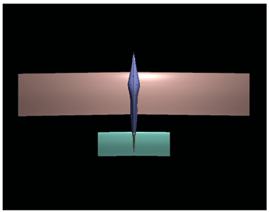
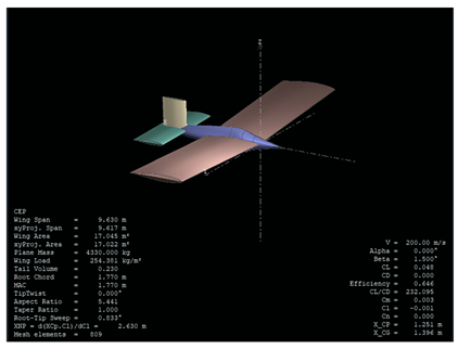
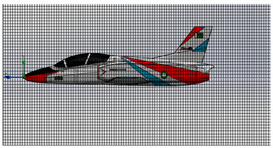
3-D Models of K-8/JL-8 are made on XFLR-5 and Solid Works based on above aircraft data.
Diffterent side views of models are as under:
Solidworks Model:
Side View:
Front View:
Top View:
XFLR-5 Model:
Side View:
Front View:
Top View:
5.3. Calculations and Graphs
Following are few assumpitions taken during the calculaions.
- Height of aircarft at which it flying is at 32000ft which is around 9.8km.
- Standard atmosphere is considered with density of 1.225 kg/m3
- Speed of aircarft is around 200 m/sec.
- Angle of Attack α in case of Longtitudinal Stabilty analysis range from -10 to 10 degree with increment of 1 degree.
- Side slip angle β in case of Lateral Stability ranging from 2 to -2 degree with increment of 0.1 degree.
- α and β remain constant in case of Lateral and Longtitudinal Stabiltiy Ananlysis.
XFLR-5:
XFLR-5, which is a software tool for the analysis of subsonic aerodynamics, is mainly used to in our research study to find effects of dihedral angle of wings on Longtitudinal and Lateral Stability of K-8/J8.However,Lift to Drag ratio CL/CD, measure of the aerodynamic efficiency of an aircraft, is also calculated to show a general effect on perofmance of aircraft by changing dihedral of wing.
Longtitudinal Stability Analsysis:
Angle of Attack in case of Longtitudinal Stabilty analysis range from -10 to 10 degree with increment of 1 degree.
| S.NO | DIHEDRAL ANGLE | Cm0 | Cma |
| 0 | -0.00377 | 0.013115 | |
| 3 | -0.04266 | 0.019135 | |
| 6 | -0.00190 | 0.02093 |
Following figure shows how the Cm related to Alpha in case of K-8/JL-8.
Figure 1 shows aircraft is unstable in longtitudinal direction.
Following figure shows relation relation of pitching Moment M to angle of attack alpha.
If an aircraft is longitudinally statically stable and a small increase in angle of attack will create a nose down pitching moment on the aircraft and so that the angle of attack decreases. Similarly and a small decrease in angle of attack will create a nose up pitching moment so that the angle of attack increases.But in this case it is vice-versa.
Lateral Stability Analsysis:
Side slip angle in case of Lateral Stability ranging from 2 to -2 degree with increment of 0.1 degree.
| S.NO | DIHEDRAL ANGLE | CLB |
| 1. | 0 | -0.00060 |
| 2. | 3 | -0.00062 |
| 3. | 6 | -0.01156 |
Figure 3 shows Aircraft K-8/JL-8 is stable in case of Lateral Stability.
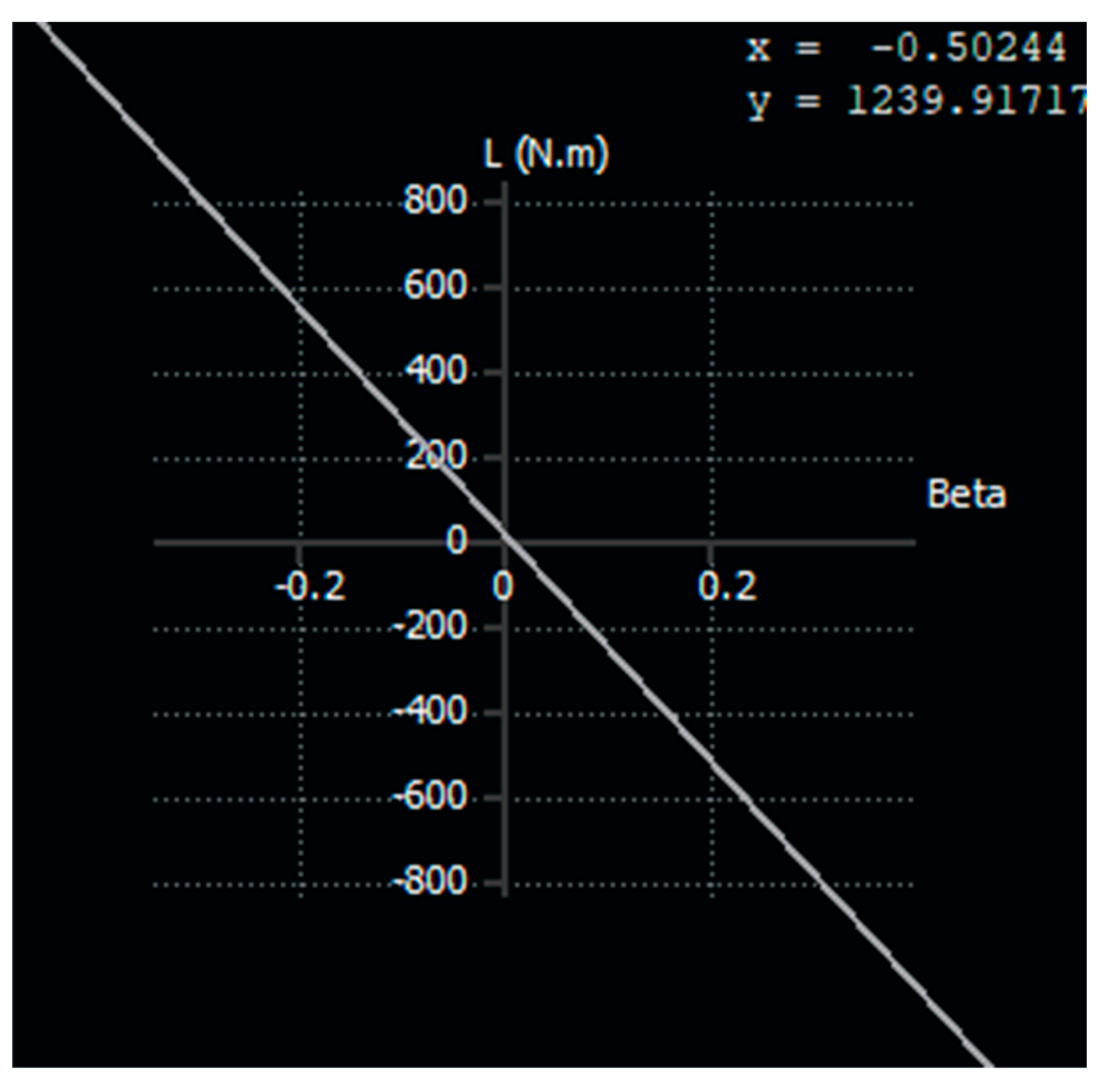
Following Figure shows relation between Rolling moment L and side slip angle β :
Figure 4 shows the how rolling moment L relates with side slip angle β.
A laterally stable aircraft responds to sideslip with a balanced combination of rolling and yawing moments and maintaining controlled flight.
Aerodynamic Effeciency: (CL/CD)
Aerodynamic Effeciency results given by XFLR-5 at zero degree side slip angle β and angle of attack is 2 dgree.
| S.NO | DIHEDRAL ANGLE | CL/CD |
| 1. | 0 | 288.375 |
| 2. | 3 | 1108.854 |
| 3. | 6 | 547.182 |
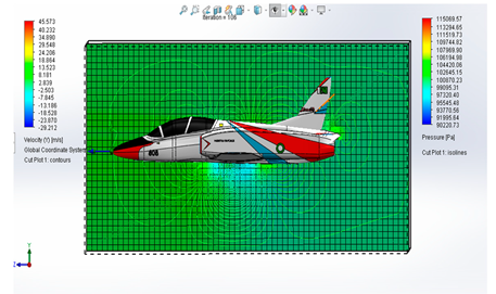
CFD Results:
Compututional Fluid analysis is done soilid works flow simulations Straight and level Flight is considered i.e at zero angle of attack.
CFD cuts the cost and time of aircraft design by simulating airflow around virtual models. It analyzes complex shapes better than traditional methods and giving engineers a deep understanding of lift and drag and how to optimize designs for better performance.
Here is the result of CL/CD on different dihedral angle of wing.
| S.NO | DIHEDRAL ANGLE | CL/CD |
| 1. | 0 | 7.084 |
| 2. | 3 | 5.4074 |
| 3. | 6 | 2.2667 |
Meshing:
Effects of Veloctiy and Pressure on Aircarft:
6. Analysis of Analytical Work
A comprehensive analysis of graphs and calculations obatined from XFLR-5 and CFD is as under:
Longtitudnal Stability:
- Initially,K-8/JL-8 is unstable in lateral axis as Cmo is negative and Cma is positive which is opposite to the definition of longtitudinal stabiltiy.
- Data of Cmo shows us that on increasing dihedral angle form 0 degree to 6 degree,its value tends towards positive value producing a stability effects.
- Data of Cma shows us that on increasing dihedral angle form 0 to 6 degree,its value tend towrads more positive value which producing a unstable effects
- So,overall effect is unstable in pitch for K-8/JL-8.
- Since aircarft is unstable, a small increase in angle of attack creates a nose up pitching moment and further increasing the angle of attack and pushing the aircraft away from its original position. This makes the aircraft difficult to control and potentially dangerous.
- Also it is worth note that Xac (1.14m) lies before Xcg (1.396m) which in view of literature means that Aircarft will be unstable in ptiching.
Lift is directly proportional to angle of attack and nose up moment is directly proportional to lift in case of Xac ahead of Xcg. If the AC is ahead of the CG, any disturbance will increase the angle of attack, leading to a further increase in lift and pitching moment, which amplifies the disturbance instead of correcting it.
Lateral Stability:
- Initially,K-8/JL-8 is stable in longtitudinal axis as Clb is negaitve which is opposite to the definition of longtitudinal stabiltiy.
- Data of Clb shows us that that on increasing dihedral angle form 0 degree to 6 degree,its value tends towards negative value which is produce more stability effects.
- So,overall increasing dihedral have stabilizing effects on rolling of aircarft.
Comaprison of CFD on XFLR-5 Vs Solidworks
Results of both XFLR-5 anf CFD shows us that aerodynamic effiiency CL/CD ratio suggests that dihedral angle 3 is optimal angle for high lift to drag ratio.
7. Comparison of Literaute Review and our Findings
Based on the findings from our analytical work and the literature review , here’s a comparison between them:
- Longitudinal Stability Literature suggests that longitudinal stability is crucial for an aircraft’s equilibrium an control. Our findings align with this and indicatin’ that the K 8/JL 8 is initially unstable longitudinally due to a negative Cmo and a positive Cma which contradicts the typical definition of longitudinal stability.
- Effect of Dihedral Angle increasing the dihedral angle tends to improve stability and as supported by literature that discusses the positive impact of dihedral on lateral stability. Our data reflects this trend , showing a move towards positive values for stability effects.
- Studies confirm that pitch instability can arise when the aerodynamic center (AC) is ahead of the center of gravity (CG) and as disturbances increase the angle of attack and leading to a nose up pitching moment.Our analysis indicates that the K 8/JL 8 exhibits this behavior and making it difficult to control.
- The literature review and our data both suggest that an increase in dihedral angle enhances lateral stability Clb which is consistent with the general understanding that a negative in the longitudinal axis indicates stability.
- Both our results and literature indicate that aerodynamic efficiency, measured by the CL/CD ratio, decreases with an increase in dihedral angle and which could be due to increased induced drag.
- Comparative studies between CFD and XFLR 5 show that while both can predict trends in aerodynamic performance and difference in absolute values can occur due to differences in the precision of the methods.
- The inherent stability of an aircraft and as discussed in literature and is determined by its configuration and including geometry and weight and and CG location. Our findings on the K 8/JL 8’s instability due to the AC being ahead of the CG corroborate this principle.
- These points provide a comprehensive comparison of my findings with established literature and highlighting the importance of dihedral angle of aircraft configuration on stability and control.
8. Results
Following is result of our finding keeping in view literature.
- The K 8/JL 8 exhibits initial instability in the lateral axis and with a negative Cmo and a positive Cma contrary to the expected behavior for stable longitudinal flight.
- Increasing the dihedral angle from 0 to 6 degrees influences Clb to approach a positive value and indicating a trend towards stability and while Cma becomes more positive and suggesting an increase in instability.
- The aircraft’s aerodynamic center (AC) located at 1.14m ahead of the center of gravity (CG) at 1.396m implies inherent pitching instability. Any disturbance increases the angle of attack and leading to a nose up moment and further instability.
- Lift is directly proportional to the angle of attack and the nose up pitching moment is directly proportional to lift when the AC is ahead of the CG. This configuration amplifies disturbances rather than dampening them.
- Initially and the K 8/JL 8 is laterally stable and as indicated by a negative rolling moment coefficient Clb and which aligns with the expected behavior for stable lateral flight.
- An increase in the dihedral angle enhances lateral stability by causing Clb >to become more negative and thus improving the aircraft’s ability to return to level flight after a disturbance.
- Considering both stability and aerodynamic performance and a dihedral angle of 3 degrees is optimal for the K 8/JL 8. It provides a balance between the positive stability effects and the minimal impact on aerodynamic efficiency and making it the most suitable choice for maintaining controlled flight.
These results reflect the relation between aircraft design parameters and stability characteristics and highlighting the critical balance required for stable flight dynamics.
10. Conclusions
Conclusion of this research study shows following critical points:
- The K 8/JL 8 shows initial pitch axis instability with a negative Cmo and a positive Cma and which shows aircraft is unstable in
- An increase in dihedral angle from 0 to 6 degrees shifts Cmo towards a positive value and suggesting a move towards stability and but also Cm1 increases positively and contributing to instability.
- The AC located at 1.14m ahead of the CG at 1.396m indicates a tendency for pitch instability and leading to control challenges if the aircraft is disturbed.
- The aircraft exhibits lateral stability and as shown by a negative Clb
- which is enhanced by increasing the dihedral angle and thus improving roll stability.
- A dihedral angle of 3 degrees is seemed optimal and balancing the need for stability in both the pitch and roll axes while maintaining good aerodynamic performance.
- This research Paper provide a good overview of how dihedral angle effects the Stability and aerodynamic effeciency of aircraft specially K-8/JL-8.
11. Further Research
This research paper will open a gate way for other researchers to investigate the relationship between dihedral angle of wing aircraft to enhance design of aircraft.
Future research should be based on optimizng control and stabilty of aircraft.
Acronyms
Some of the acronyms used in the paper are as follows:
| α | Angle of attack |
| β | Side slip angle |
| Q | Dynamic pressure |
| Λ | Sweep angle |
| Γ | Dihedral angle |
| Xcg | Centre of gravity location |
| Xac | Aerodynamic centre location |
| Xnp | Neutral point location |
| Ix | Moment of inertia about x |
| Iy | Moment of inertia about y AR Aspect ratio |
| b | Wing span |
| c | Mean aerodynamic chord |
| S | Planform area |
| M | Mach no |
| W | Weight of the aircraft |
| m | Mass of aircraft |
| Y | y-direction force |
| Z | z-direction force |
| L | rolling moment |
| M | pitching moment |
| N | yawing moment |
| ϕ | Bank angle |
| ψ | Yaw angle |
| CL | Co-eff of lift |
| CD | Co-eff of drag |
References
- “Performance, Stability, Dynamics & Control of Airplanes” by Bandu N. Pamadi, AIAA Education Series, 3rd Edition, 2015.
- Dr. R. C. Nelson “Flight Stability and Automatic Control”. 2nd ed., Tata McGraw Hill, Ed. NEW DELHI,2007, pp. 35-170.
- SAMPAIO, Ronivaldo Passos. Sistema de controle de atitude embarcado para voo autônomo de aviões em escala. 2006. 186 f. Dissertação (Mestrado em Mecatrônica). Escola Politécnica e instituto de matemática - Universidade Federal da Bahia, Salvador.
- DANTAS, André. “A inteligência das máquinas – terceira parte”, 2014.
- HURT JR, Hugh H. Aerodynamics for Naval Aviators, University of Southern California, Federal Aviation Administration, Regulation Policies, consulted in 2015.
- E. R. S. Teixeira, B. H. de F. Yokota, D. Ferreira Neto, P. A. M. Pimentel, S. P. S. dos Santos, L. B. dos Santos, and A. C. Kieling, “The Study and Analysis of Using Wing Dihedral on the Side of an Aircraft’s Static Stability,” presented at the International Conference on Mechanical Engineering, 2015.
- “K-8,” Pakistan Aeronautical Complex, Available: https://web.archive.org/web/20190426092731/https://www.pac.org.pk/k-8, Accessed: Mar. 10, 2024.
- R. R. G. a. M. D. White, “Analysis and prediction of longitudinal stability of airplanes,” NTRS, 1941.
Figure 1.
XX.
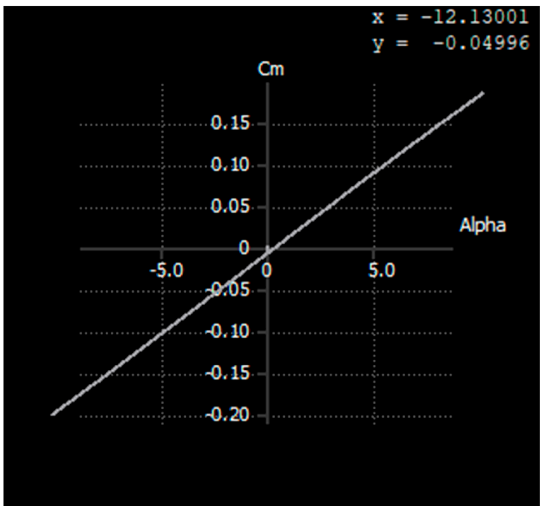
Figure 2.
XX.
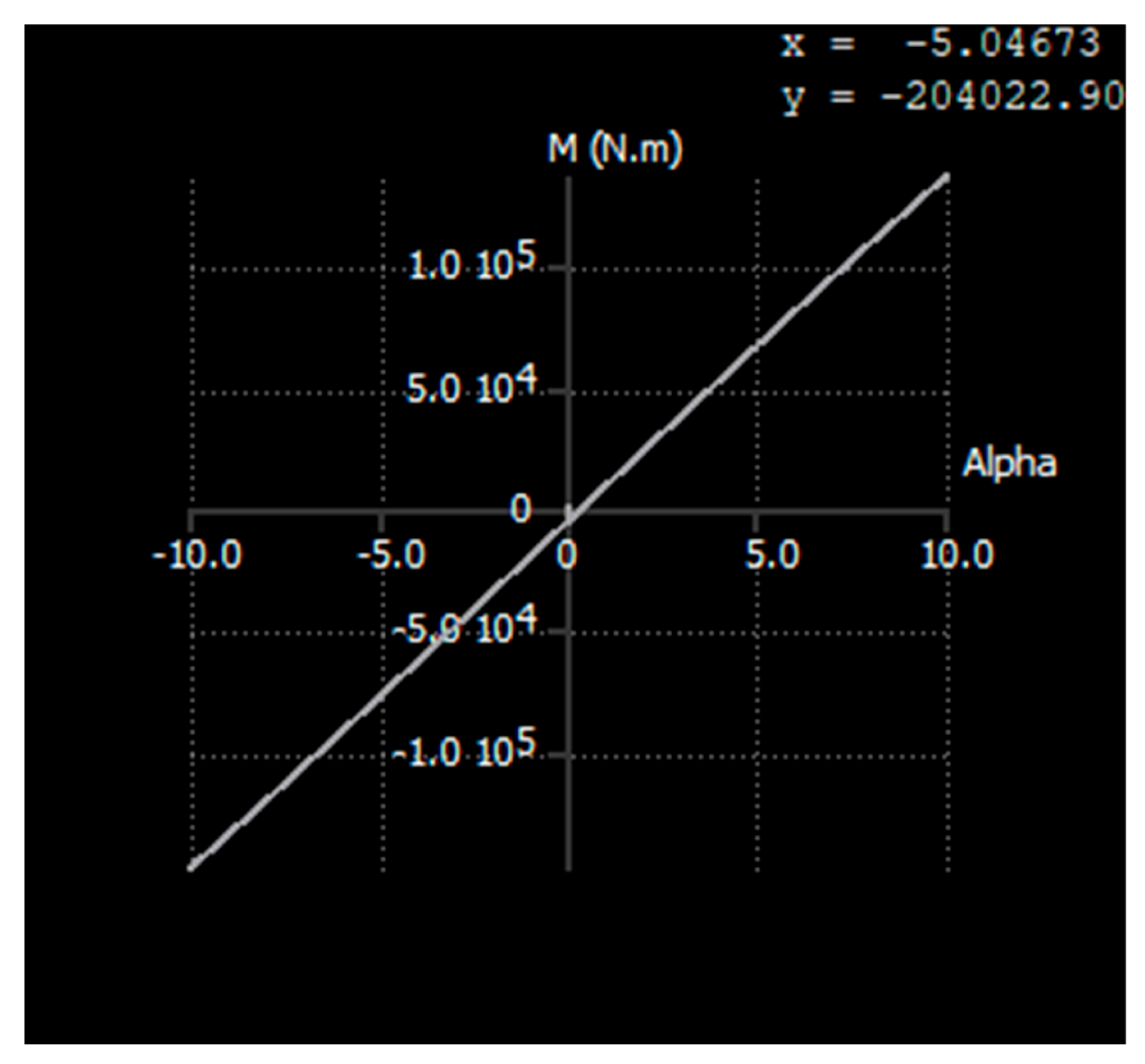
Figure 3.
XX.
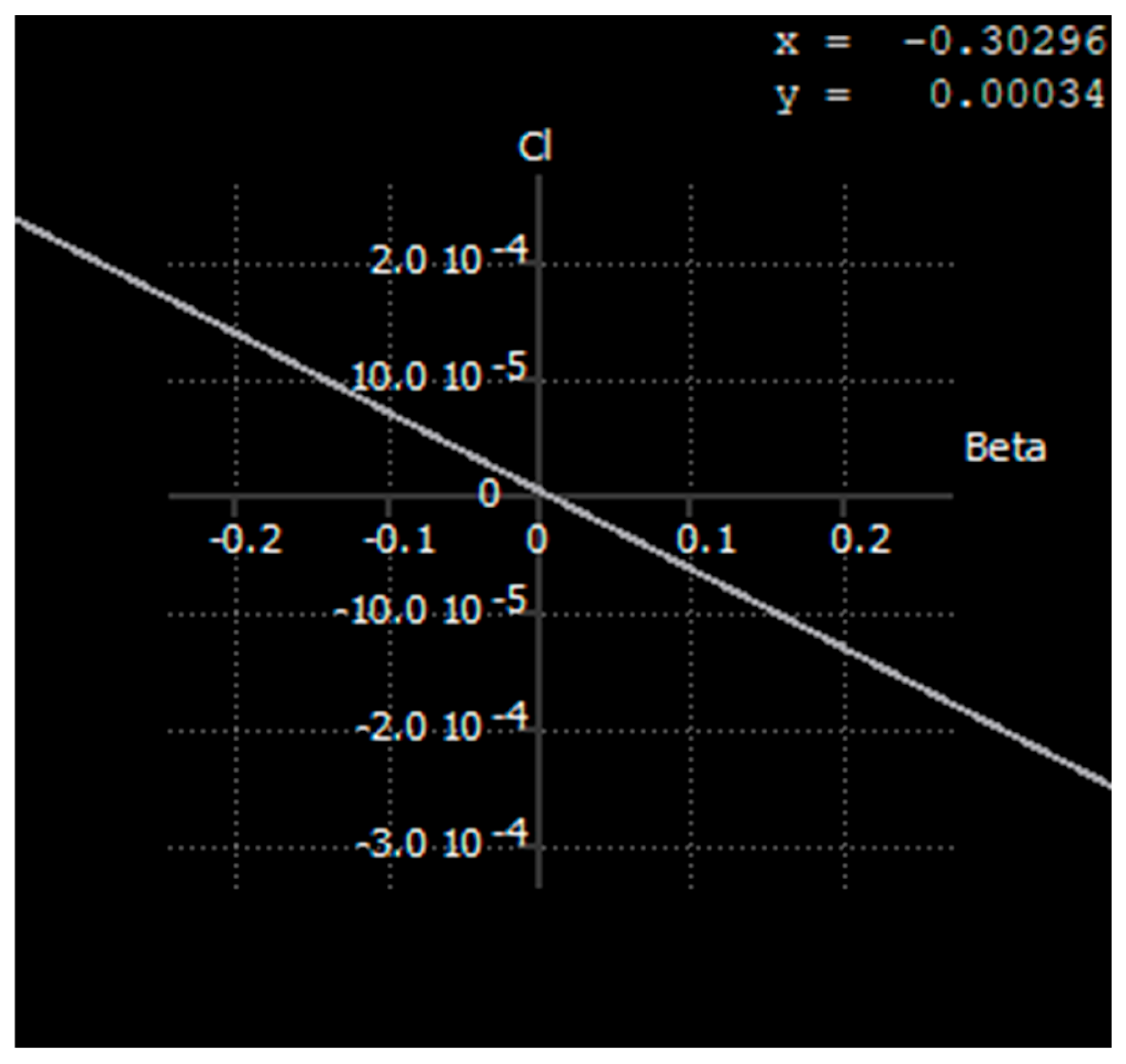
Figure 4.
XX.
Disclaimer/Publisher’s Note: The statements, opinions and data contained in all publications are solely those of the individual author(s) and contributor(s) and not of MDPI and/or the editor(s). MDPI and/or the editor(s) disclaim responsibility for any injury to people or property resulting from any ideas, methods, instructions or products referred to in the content. |
© 2025 by the authors. Licensee MDPI, Basel, Switzerland. This article is an open access article distributed under the terms and conditions of the Creative Commons Attribution (CC BY) license (http://creativecommons.org/licenses/by/4.0/).
Copyright: This open access article is published under a Creative Commons CC BY 4.0 license, which permit the free download, distribution, and reuse, provided that the author and preprint are cited in any reuse.


