Submitted:
28 February 2025
Posted:
03 March 2025
You are already at the latest version
Abstract
Addressing the limitations of restricted coding capacity and material dependency in acoustic identity tags for autonomous underwater vehicles (AUVs), this study intro-duces a novel passive acoustic identification tag (AID) design based on multilayered elastic cylindrical shells. By developing a Normal Mode Series (NMS) analytical model and validating it through finite element method (FEM) simulations, the work elucidates how material layering strategies regulate far-field target strength (TS) and establishes a time-domain multi-peak echo-based encoding framework. Results demonstrate that optimizing material impedance contrasts achieves 99% detection success at a 3dB sig-nal-to-noise ratio. Jaccard similarity analysis of 3,570 material combinations reveals a system-wide average recognition error rate of 0.41%, confirming robust encoding reli-ability. The solution enables combinatorial expansion of coding capacity with structural layers, yielding 210, 840, and 2,520 unique codes for 3-, 4-, and 5-layer configurations, respectively. These findings validate a scalable, hull-integrated acoustic identification system that overcomes material constraints while providing high-capacity encoding for compact AUVs, significantly advancing underwater acoustic tagging technologies through physics-driven design and systematic performance validation.
Keywords:
Autonomous Underwater Vehicles (AUVs)
; Passive acoustic identification tags
; Multi-layered elastic cylindrical shells
; Normal Mode Series (NMS)
; Finite Element Method (FEM)
; Target Strength (TS)
; Jaccard similarity analysis
; Encoding capacity scaling
1. Introduction
With the advancement of materials science and computational theory, the use of Autonomous Underwater Vehicles (AUVs) in marine industries has significantly increased. Compared to manned/remotely operated underwater vehicles, AUVs have demonstrated superior reliability and cost-effectiveness in executing underwater missions [1]. To efficiently and stably accomplish complex tasks—such as pipeline inspections for oil and gas industries, oceanographic observations, bathymetric surveys, military applications, high-resolution seabed inspections, mapping, commercial explorations, and neutralization of seabed mining areas—in unknown underwater environments, formation control of AUVs has emerged as a critical research focus [2]. Concurrently, theories related to radio frequency, optical, and acoustic communication have been continuously developed to enhance data transmission capabilities between AUVs in underwater environments [3]. Among these, active and passive positioning between AUVs is regarded as a fundamental prerequisite for mission execution [4].
For AUV identification and localization, traditional transponder-based methods face limitations in deployment/maintenance costs and device power constraints. Optical approaches are restricted by critical factors such as lighting conditions, turbidity, and feature richness [5], with localization accuracy varying by up to an order of magnitude across different vision-based algorithms [6]. Meanwhile, sonar-based simultaneous localization and mapping (SLAM) techniques incur high computational costs and exhibit significant uncertainties under complex environmental conditions [7].
To address these challenges, a series of novel AUV underwater identification and localization methods have been continuously proposed. These include the establishment of underwater artificial landmarks detectable by cameras or optical sensors [8], though vision-based solutions are limited to short-range applications. In response, Satish et al. [9,10] introduced the concept of a passive Acoustic Identification Tag (AID). This tag reflects unique acoustic characteristics when interrogated by sonar pulses, enabling it to function as a low-maintenance, cost-effective navigation aid. Inspired by passive surface acoustic wave RFID tags [11], AID tags modulate parameters such as acoustic material type, arrangement, and thickness to generate distinctive acoustic signatures. Building on this concept, Bhardwaj et al. [12] developed an AID tag capable of infinite ultrasonic wireless power transfer and backscatter-based localization.
Concurrently, leveraging SonarBell Corporation's research on polymer target acoustic scattering [13], Zhou et al. [14] experimentally validated the feasibility of passive acoustic markers utilizing Rayleigh wave resonance in biaxially oriented acrylic spheres. Satish et al. [15] further optimized the design of multi-layered hemispherical shell AID tags. Following this methodology, Somaan et al. [16] demonstrated the viability of concentric acrylic-based AID tags for AUV navigation and positioning through field trials. Ding Dong et al. [17] established the feasibility of time-domain echo coding using four-layer elastic spherical shells. Most recently, Zhou et al. [18] achieved a breakthrough by combining periodic rib-plate and helical groove structures with polymethyl methacrylate (PMMA) multi-sphere assemblies, successfully integrating time-frequency domain scattering features with geometric-elastic characteristics. This work verifies the practicality of acoustic coding and pioneers new approaches for intelligent underwater target recognition.
While the aforementioned studies on AID tags provide efficient and low-cost solutions, their limited information density and the size constraints of dual-sphere configurations (e.g., radius 0.05 m, spacing 0.25 m) [14] may render them unsuitable for AUVs. Furthermore, the multilayer shell design proposed by Satish et al. [15] necessitates precise control over layer thicknesses and material properties (e.g., impedance matching between acrylic and water). Nonuniform interlayer water gaps could lead to encoding distortions.
This paper proposes an AID tag design method for multilayer elastic cylindrical shell structures, integrable onto AUV hull surfaces, based on the Normal Mode Series (NMS) [19]. By developing an analytical model for acoustic scattering in multilayer shells and validating it via finite element method (FEM) simulations, we quantitatively analyze the impact of material stratification strategies on far-field Target Strength (TS). Additionally, a coding generation and recognition methodology is introduced, leveraging the specificity of time-domain echo characteristics.
2. Materials and Methods
2.1. Theoretical Foundation
In the cylindrical coordinate system, the elastodynamic behavior of an infinite multilayered elastic cylindrical shell under normally incident plane wave excitation is investigated using the displacement potential function method. Let the wave vector of the incident wave be . The -direction displacement in the elastic cylindrical structure can be fully characterized using two scalar potential functions (dilatational) and (shear), which satisfy the Navier-Cauchy equation:
Figure 1.
Plane wave incident on an infinitely long multi-layered elastic cylindrical shell.
The internal solutions within the elastic cylinder derived through the separation of variables method are expressed as:
where , , ,. Let and denote the Lamé constants of the -th elastic layer, where the subscript identifies the layer index in the multilayered cylindrical structure, , represent the Bessel function and the Neumann function. [19]
The displacements and stresses must satisfy the following continuity conditions:
The exterior and interior acoustic fields of the cylinder can be expressed as:
where denotes the Hankel function of the first kind.
By applying the continuity conditions for stress and displacement, we derive the system of equations for an infinitely long cylindrical shell with an exterior fluid medium and an interior air-filled cavity. The matrix dimensionality is dependent on the number of layers – for instance, a 2-layer shell corresponds to a 6×6 matrix, 3-layer to 10×10, 4-layer to 14×14, and so forth. The solution to the system is given by , with matrix elements detailed in Appendix A.
When a plane wave is incident normally on an infinitely long cylindrical shell, the scattered sound pressure can be expressed as:
Target Strength (TS) is defined as:
where denotes the scattered sound pressure, represents the incident sound pressure, and is the reference distance.
Similarly, the reflection coefficient and the average power reflection coefficient can be determined using the Normal Mode Series (NMS) method.
2.2. Numerical Verification
To validate the reliability of the NMS model, four representative material combinations from Table 1 (e.g., Al-AA, PMMA-PVC-PETG) were used to construct multilayer cylindrical shells with a radius of 0.25 m and a layer thickness gradient of 0.01 m (innermost structural steel layer: 0.002 m). A finite element model (FEM) was developed in COMSOL Multiphysics (mesh size: , where is the acoustic wavelength), as illustrated in Figure 2.
Computational results from both the Normal Mode Series (NMS) and Finite Element Method (FEM) for a cylindrical shell with radius , constructed using selected materials from Table 1, are shown in .
2.3. AlD Tag Generation Workflow
As shown in Figure 3, comparative analysis reveals that for multilayer shell structures of varying materials, the theoretical analytical solutions and numerical simulation results for far-field target strength (TS) exhibit remarkable consistency in spatial distribution characteristics across the reduced frequency range , where is the wavenumber and the shell radius.
Based on the frequency-domain indirect method [20], a Gaussian-windowed tone burst with a center frequency and fractional bandwidth was employed as the excitation signal. The frequency-domain backscattered sound pressure of the multilayer cylindrical shell was calculated, and the time-domain echo was obtained via inverse Fourier transform. The governing equations are as follows:
where represents the theoretical transfer function derived from the Normal Mode Series (NMS) scattering model.
Gaussian-windowed tone burst:
where governs the pulse duration, (time variable), (temporal center), and (center frequency).
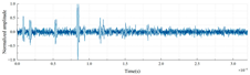
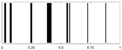
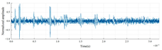
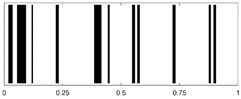
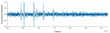
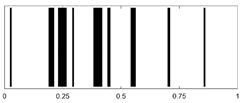
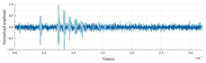
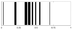
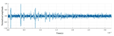
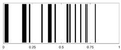
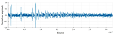
To extract the time-domain echo peak features from the acoustic backscatter signals of cylindrical shells under different stratification strategies, a matched filtering technique is employed by convolving the echo signal with the incident signal. Simultaneously, positional information of distinct peak points and peak interval sequence information are extracted, quantized, and encoded into a 1D barcode. The detailed workflow is illustrated in Figure 4.
For a three-layer cylindrical shell with an outermost radius of 0.25 m and a uniform shell thickness of 0.01 m per layer, optimized stratification strategies enable the generation of distinct time-domain echo characteristics. These features are encoded into corresponding AID tags, demonstrating unique acoustic fingerprints for material-layer configurations.
Wenz [21] systematically classified the ocean noise spectrum for the first time, delineating the frequency distributions of natural sources (wind, waves, marine life) and anthropogenic sources. High-frequency noise is predominantly thermal noise generated by molecular thermal motion (Brownian motion) in seawater, with noise level decreasing as frequency increases. To validate the effectiveness of AID tags, this study added Gaussian white noise (uniformly distributed across all frequencies, signal-to-noise ratio (SNR) = 3 dB) to the echo signals and performed the Shapiro-Wilk normality test [22]. The results confirmed that the added noise followed a normal distribution. The signal-to-noise ratio [23] (SNR) is defined as the ratio of signal power to noise power (in decibels, dB):
where denotes the signal power and represents the noise power.
3. Verifications and Results
3.1. Effectiveness of AID Tags
Time-domain echo signals and their corresponding AID tags for different material layer arrangements in a three-layer cylindrical shell (outer radius: 0.25 m, uniform layer thickness: 0.01 m) are shown in Table 2.
The barcodes in Table 2, when decoded, exist as 0-1 binary sequences at the host terminal. For binary existence-based set data, target recognition can be performed using the Mean Jaccard Index (MJI) [24], as defined in Equation (16). To enhance recognition accuracy, multiple sampling analyses were conducted, with the aggregated results presented in Table 3.
AUVs typically employ aluminum alloys or high-strength steel for structural frames and pressure hulls [25]. To further analyze the impact of metallic backplates on AID tag feature recognition, an additional thin metal layer (0.002 m) was introduced under the same conditions as Table 3 for MJI detection comparison. The results are presented in Table 4.
For cylindrical shells internally filled with air, the addition of rigid internal structures has minimal impact on target feature recognition, as demonstrated in Table 3, where the average recognition rate remains largely unchanged.
To further investigate the diversity and effectiveness of AID tags, seven materials from Table 1 (excluding water, structural steel, and aluminum) were selected. The study systematically controls material permutation sequences and layer counts, with the specific combinatorial configurations quantified in Table 5.
A Jaccard similarity coefficient comparison was conducted between a total of 3,570 datasets and their corresponding counterparts with added Gaussian noise, with the results illustrated in Figure 5.
As illustrated in the heatmap in Figure 5, the red points within the circled area represent recognition errors caused by the co-arrangement of materials with similar impedance. Statistical analysis reveals that these errors are most significantly influenced by the distinct layered combinations of Acrylic Acid (AA), PMMA, and PVC. The average power reflection coefficients for these three materials under varying combinations are shown in Figure 6.
As shown in Figure 7, when materials with low acoustic impedance differences are employed, the average power reflection coefficient remains below 0.05 at a thickness of 0.01 m. This diminishes the characteristic features of the target echo, necessitating the avoidance of layered configurations using materials with closely matched acoustic impedance.
As delineated in Figure 7, the intervals 1–210, 211–1050, and 1051–3570 correspond to 3-, 4-, and 5-layered media, respectively. A 95% confidence interval Bootstrap resampling analysis [26] was applied to calculate the Jaccard similarity coefficients between noise-containing and noise-free echo signals from identical materials in the diagonal regions of the heatmap. The analysis utilized a sample size matching the original dataset and 10,000 resamples, with results summarized in Table 6.
The global confidence interval for all combinations in Table 5 is [94.70%, 94.82%], confirming the statistical reliability of the system over a wide parameter range.
To further quantify the impact of the aforementioned material arrangements on the detection accuracy of AID tags, error rates with and without these arrangements were repeatedly calculated under a 3 dB signal-to-noise ratio (SNR). Higher error rates indicate stronger influence of material configurations on target recognition. The results are presented in Figure 8.
As shown in Figure 9, the detection error remains around 12% when using the aforementioned material combinations. In contrast, avoiding these materials significantly reduces the error rate, with an average detection error rate of merely 0.41%. Interfering material arrangements that disrupt target recognition are substantially minimized. Furthermore, systematic screening can exclude specific combinations to further reduce errors.
3.2. Target Recognition Methodology
Following the reduction in average detection error, the data stored in AID tags can be more effectively leveraged for target recognition. The proposed methodology for target recognition is described below, with its detailed workflow illustrated in Figure 9.
Upon acquiring the noise-containing time-domain echo signal, the corresponding AID tag can be generated. This tag is converted into its binarized form after host retrieval. The binarized data is then compared with its noise-free counterpart using the Jaccard similarity coefficient, yielding a column vector of Jaccard similarity coefficients. Subsequently, cosine similarity [27] is computed between this vector and the Jaccard matrix, as expressed in Equation (17). To further enhance recognition accuracy, the TOP-K query optimization method [28] is applied.
To validate recognition stability, a column vector of Jaccard similarity coefficients was compared with 20 additional Jaccard matrices under 3 dB SNR noise interference for similarity recognition trials. Validation shows that the computation time for the Jaccard column matrices referenced in Figure 9 is approximately 0.005 seconds. The full Jaccard matrix computation time remains below 0.5 seconds (matrices are precomputed and stored in the database, eliminating additional computational overhead). Finally, the processing time for column-to-matrix matching in target recognition is around 1.5 seconds, The calculation is carried out based on the matrix of the maximum dimension, which can be further reduced when matching with lower-dimensional matrices.
As demonstrated in Figure 10, the detection error rate exhibits a significant reduction with increasing matching dimensionality, with the overall detection success rate reaching 99%.
4. Conclusion
This study addresses the high-density identification requirements for autonomous underwater vehicles (AUVs) by proposing a passive acoustic identification tag (AID) design based on multilayered elastic cylindrical shell structures. Through theoretical modeling using the normal series method, finite element numerical validation, and large-scale material combination simulations, we elucidate the regulatory mechanisms of material layering strategies on far-field acoustic scattering characteristics and establish a time-frequency domain fusion encoding system with high robustness. The results demonstrate that the proposed scheme achieves competitive performance in encoding capacity and noise resistance, offering an innovative solution for underwater collaborative navigation. Key findings include:
By adjusting the material stacking sequence and impedance matching in multilayered elastic cylindrical shells, distinctive time-domain multi-peak echo features can be engineered. These features enable high-information-density encoding via peak interval sequences, while optimized impedance differences effectively suppress encoding distortion.
Under 3 dB SNR conditions, Jaccard similarity analysis and Bootstrap resampling quantify the influence of layering strategies on encoding uniqueness. Combined with rapid matching algorithms (single recognition cycle <1.5 s) and noise-resistant processing, the system achieves 99% recognition success rates in complex acoustic environments.
Increasing the number of material layers significantly expands encoding combinations: 3-, 4-, and 5-layer structures generate 210, 840, and 2,520 unique codes, respectively (Table 4). This represents a substantial improvement over traditional dual-sphere tags, which offer only a limited number of combinations.
Author Contributions
Conceptualization, Z.P.; methodology, Z.D., S.X., and Z.P.; software, Z.D.; validation, Z.D.; formal analysis, Z.D.; investigation, Z.D. and S.X.; resources, Z.D. and Z.P.; data curation, Z.D.; writing—original draft preparation, Z.D.; writing—review and editing, Z.D., Z.P., and S.X.; visualization, Z.D. and Z.P.; supervision, Z.P. and S.X.; project administration, Z.P. and S.X.; funding acquisition, Z.P. All authors have read and agreed to the published version of the manuscript.
Funding
National Natural Science Foundation of China (52201397); Laboratory of Science and technology on integrated Logistics Support, National University of Defense Technology (WDZC20235250311); Open Fund of Ship Vibration and Noise Key Laboratory (6142204230709, 6142204240202), Natural Science Foundation of Hunan Provincial (2023JJ60544).
Institutional Review Board Statement
Not applicable.
Informed Consent Statement
Not applicable.
Data Availability Statement
All evaluated data are presented in this paper in graphical form. Original data of this study are available upon request from the corresponding author.
Conflicts of Interest
The authors declare no conflicts of interest.
Appendix A
The distribution of matrix elements of multi-layer cylindrical shells follows certain rules. Taking the double-layer cylindrical shell as an example, the boundary conditions are introduced at the contact surface between the external fluid and the solid to solve for:
,,,,
,,,,
,
,
,
,
,
,
,
,
where correspond to the negatives of ,, respectively. Following this pattern, matrices for elastic media interactions in multi-layered shells can be extended by successively stacking and arranging according to the established rules. Taking a two-layered cylindrical shell as an example, the internal acoustic field is expressed as:
,
,
,
,,
,,,,
,
,
,
,
,
For , simply replace and with and , where:
,.
References
- Wernli R, L. AUV commercialization-who's leading the pack?[C]//Oceans 2000 Mts/ieee Conference and Exhibition. Conference Proceedings (cat. No. 00ch37158). IEEE 2000, 1, 391–395. [Google Scholar] [CrossRef]
- Yang Y, Xiao Y, Li T. A survey of autonomous underwater vehicle formation: Performance, formation control, and communication capability[J]. IEEE Communications Surveys & Tutorials 2021, 23, 815–841. [Google Scholar] [CrossRef]
- Gussen C M G, Diniz P S R, Campos M L R, et al. A survey of underwater wireless communication technologies[J]. J. Commun. Inf. Sys 2016, 31, 242–255. [Google Scholar]
- Maurelli F, Krupiński S, Xiang X, et al. AUV localisation: a review of passive and active techniques[J]. International Journal of Intelligent Robotics and Applications 2022, 6, 246–269. [Google Scholar] [CrossRef]
- González-García J, Gómez-Espinosa A, Cuan-Urquizo E, et al. Autonomous underwater vehicles: Localization, navigation, and communication for collaborative missions[J]. Applied sciences 2020, 10, 1256. [Google Scholar] [CrossRef]
- Qin J, Li M, Li D, et al. A survey on visual navigation and positioning for autonomous UUVs[J]. Remote Sensing 2022, 14, 3794. [Google Scholar] [CrossRef]
- Aulinas J, Petillot Y, Salvi J, et al. The SLAM problem: a survey[J]. Artificial Intelligence Research and Development 2008, 363, 371. [CrossRef]
- Jung J, Li J H, Choi H T, et al. Localization of AUVs using visual information of underwater structures and artificial landmarks[J]. Intelligent Service Robotics 2017, 10, 67–76. [Google Scholar] [CrossRef]
- Satish A, Nichols B, Trivett D, et al. Passive underwater acoustic tags using layered media[J]. The Journal of the Acoustical Society of America 2019, 145, EL81–EL89.
- Satish A, Trivett D, Sabra K G. Omnidirectional passive acoustic identification tags for underwater navigation[J]. The Journal of the Acoustical Society of America 2020, 147, EL517–EL522. [CrossRef]
- Jalal A S, A. Passive RFID Tags[J]. Wulfenia Journal 2015, 22, 415–435. [Google Scholar]
- Bhardwaj A, Allam A, Erturk A, et al. Ultrasound-Powered Wireless Underwater Acoustic Identification Tags for Backscatter Communication[J]. IEEE Transactions on Ultrasonics, Ferroelectrics, and Frequency Control. [CrossRef]
- Islas-Cital A, Atkins P, Gardner S, et al. Performance of an enhanced passive sonar reflector SonarBell: A practical technology for underwater positioning[J]. Underwater Technology 2013, 31, 113–122. [Google Scholar] [CrossRef]
- Zhou Y, Fan J, Huang J, et al. Passive underwater acoustic barcodes using Rayleigh wave resonance[J]. Journal of Applied Physics 2022, 131. [Google Scholar] [CrossRef]
- Satish A, Sabra K G. Passive underwater acoustic identification tags using multi-layered shells[J]. The Journal of the Acoustical Society of America 2021, 149, 3387–3405. [Google Scholar] [CrossRef]
- Somaan N, Bhardwaj A, Sabra K G. Passive acoustic identification tags for marking underwater docking stations[J]. JASA Express Letters 2024, 4.
- Ding D, Chen C X, Kong H M, et al. Acoustic encoding of high-frequency time-domain echoes from layered elastic spherical shells in water[J]. Applied Acoustics 2023, 42, 781–791. [Google Scholar]
- Zhou F, Fan J, Wang B, et al. Acoustic barcode based on the acoustic scattering characteristics of underwater targets[J]. Applied Acoustics 2022, 189, 108607. [Google Scholar] [CrossRef]
- Gaunaurd G, C. Sonar cross section of a coated hollow cylinder in water[J]. The Journal of the Acoustical Society of America 1977, 61, 360–368. [Google Scholar] [CrossRef]
- Martins, N. A Time Frequency Approach to Blind Deconvolution in Multipath Underwater Channels[D]. Universidade do Algarve (Portugal), 2001.
- Wenz G, M. Acoustic ambient noise in the ocean: spectra and sources[J]. The journal of the acoustical society of America 1962, 34, 1936–1956. [Google Scholar] [CrossRef]
- Royston, P. Approximating the Shapiro-Wilk W-test for non-normality[J]. Statistics and computing 1992, 2, 117–119. [Google Scholar] [CrossRef]
- Lucas E, Wang Z. Performance prediction of underwater acoustic communications based on channel impulse responses[J]. Applied Sciences 2022, 12, 1086. [Google Scholar] [CrossRef]
- Bag S, Kumar S K, Tiwari M K. An efficient recommendation generation using relevant Jaccard similarity[J]. Information Sciences 2019, 483, 53–64. [Google Scholar] [CrossRef]
- Zhu D, Li Q, He X, et al. Preparation of highly dewetted porous steel for shallow water AUV based on laser ablation method[J]. Applied Surface Science 2024, 652, 159261. [Google Scholar] [CrossRef]
- Martins, N. A Time Frequency Approach to Blind Deconvolution in Multipath Underwater Channels[D]. Universidade do Algarve (Portugal).
- Efron B, Tibshirani R J. An introduction to the bootstrap[M]. Chapman and Hall/CRC, 1994.
- Huang M, Chen D, Feng D. The Fruit Recognition and Evaluation Method Based on Multi-Model Collaboration[J]. Applied Sciences 2025, 15, 994. [Google Scholar] [CrossRef]
- Adomavicius G, Zhang J. Classification, ranking, and top-K stability of recommendation algorithms[J]. INFORMS Journal on Computing 2016, 28, 129–147. [Google Scholar] [CrossRef]
Figure 2.
Finite element model.
Figure 3.
Target Strength (TS) comparison: NMS analytical solutions vs. FEM results for multilayer shells (radius 0.25 m).
Figure 3.
Target Strength (TS) comparison: NMS analytical solutions vs. FEM results for multilayer shells (radius 0.25 m).
Figure 4.
Acoustic Barcode Generation Flowchart.
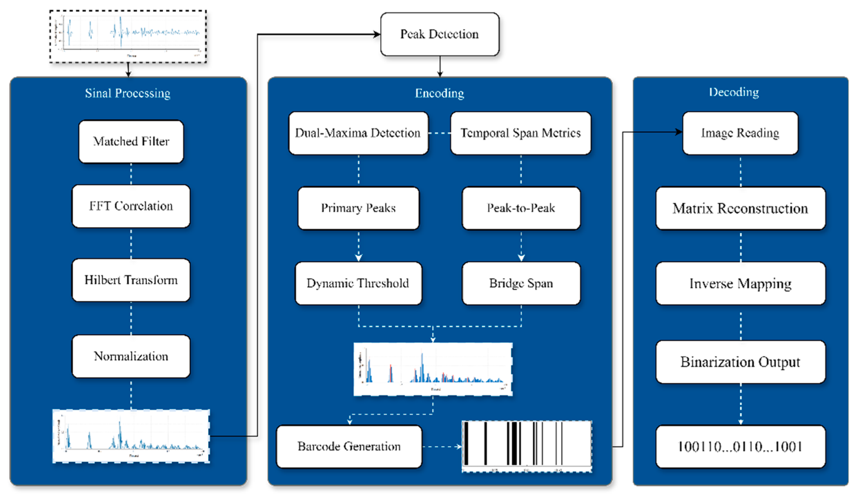
Figure 5.
Jaccard similarity coefficient heatmap with a sampling interval of 20 (including interfering material arrangements).
Figure 5.
Jaccard similarity coefficient heatmap with a sampling interval of 20 (including interfering material arrangements).
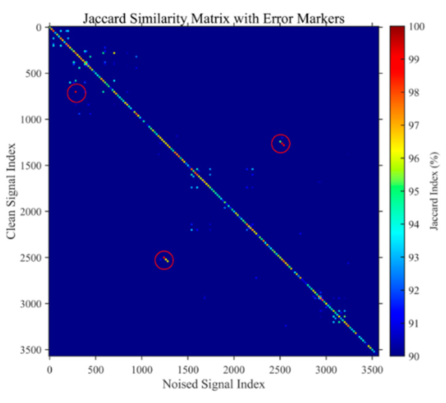
Figure 6.
Average broadband power reflection coefficients under different material arrangements.
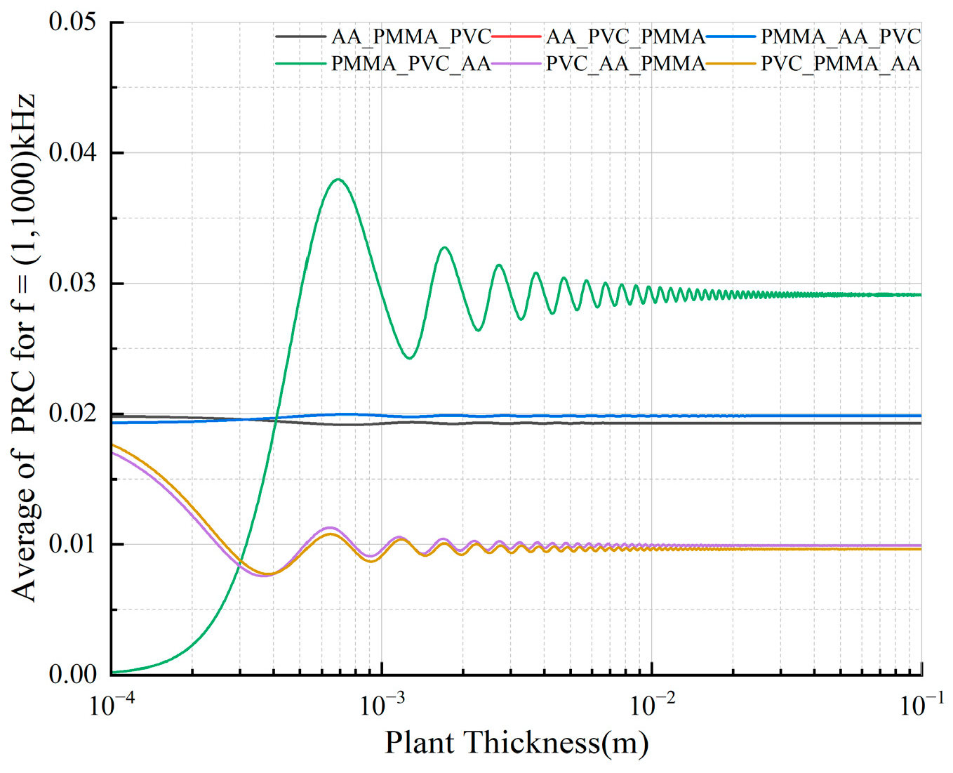
Figure 7.
Jaccard similarity coefficient heatmap with a sampling interval of 10 (excluding interfering material arrangements).
Figure 7.
Jaccard similarity coefficient heatmap with a sampling interval of 10 (excluding interfering material arrangements).
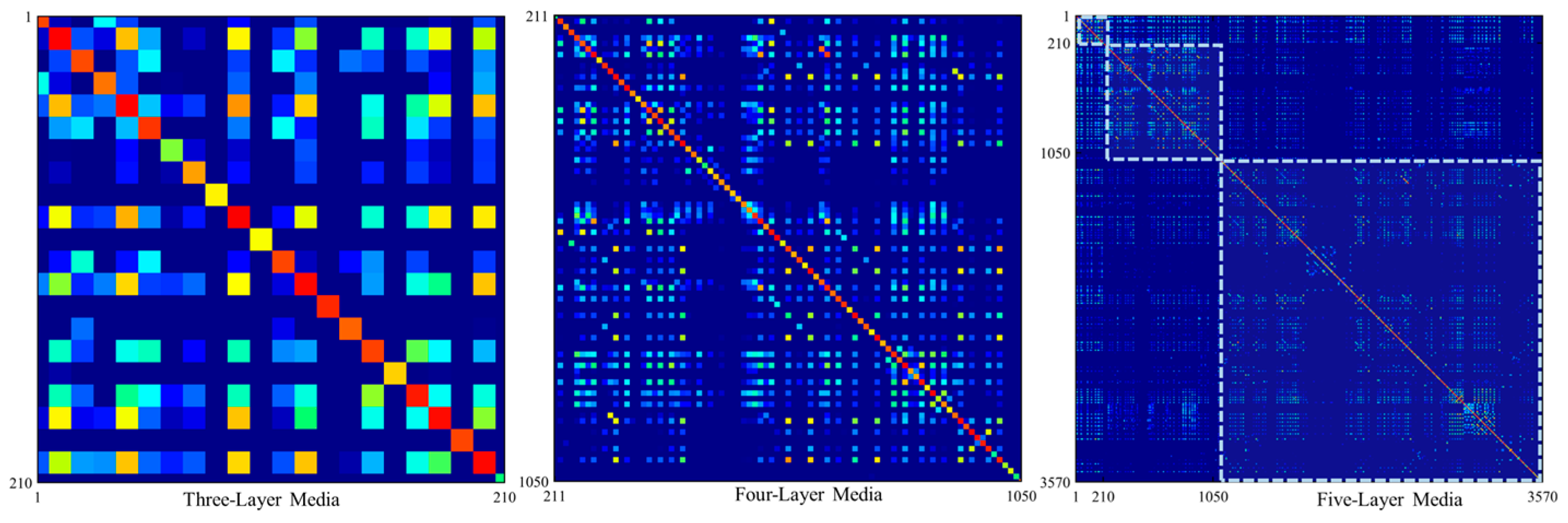
Figure 8.
Repeatedly calculated detection error values.
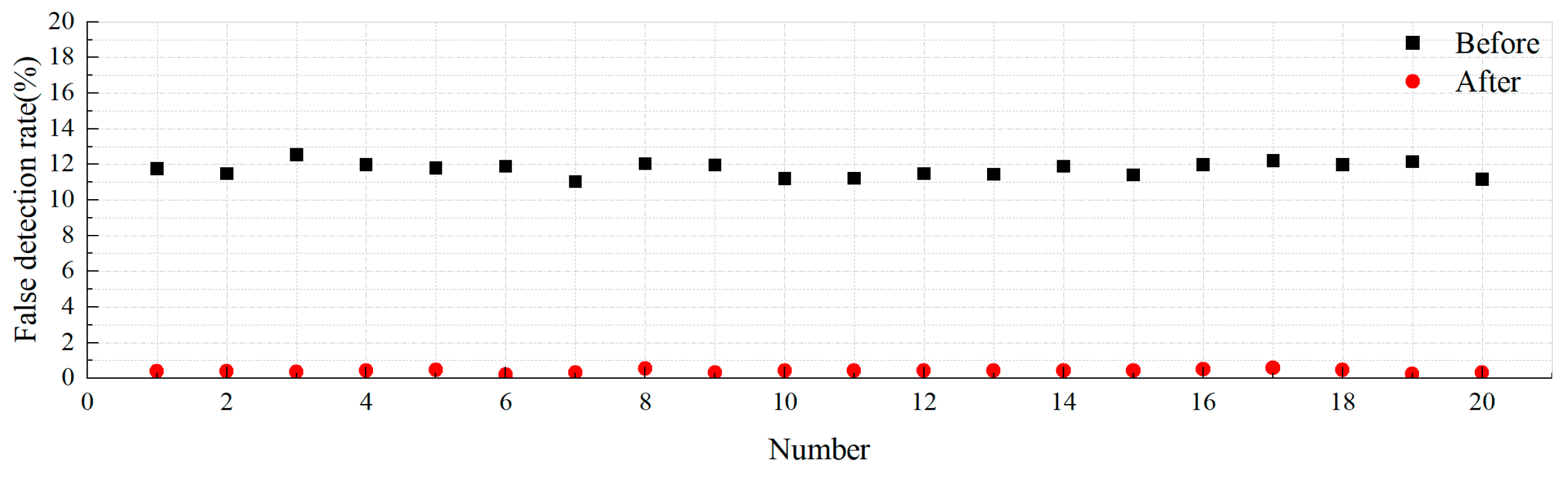
Figure 9.
Flowchart of the Target Recognition Methodology.
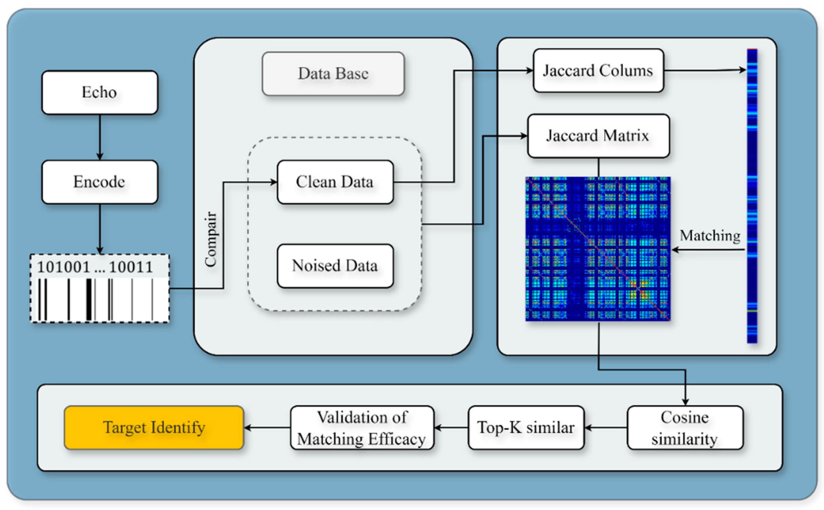
Figure 10.
Detection error rate variation with matrix dimensionality (boxplot)".
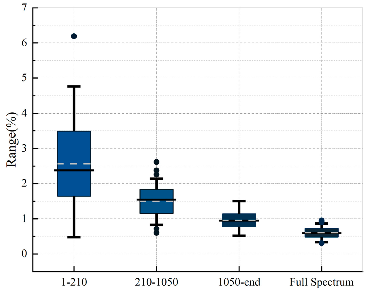

Table 1.
Properties of commonly used materials.
| Material names | Density |
Young's modulus |
Poisson's ratio |
Longitudinal
velocity |
Characteristic impedance )(megarayleighs) |
|---|---|---|---|---|---|
| Water | 1000 | / | / | 1480 | 1.48 |
| Air | 1.2 | / | / | 344 | 0.41e-3 |
| Polymethyl Methacrylate (PMMA) |
1180 | 2.8 | 0.38 | 2108 | 2.49 |
| Polyvinyl Chloride (PVC) | 1400 | 3 | 0.38 | 2003 | 2.80 |
| Polytetrafluoroethylene (PTFE) |
2200 | 0.4 | 0.37 | 567 | 1.25 |
| Polyethylene Terephthalate Glycol-modified (PETG) | 1270 | 2 | 0.37 | 1669 | 2.12 |
| High-Density Polyethylene (HDPE) | 970 | 1.5 | 0.4 | 1820 | 1.77 |
| Low-Density Polyethylene (LDPE) | 910 | 0.1 | 0.45 | 646 | 0.59 |
| Acrylic Acid (AA) | 1190 | 3.2 | 0.35 | 2078 | 2.47 |
| Aluminum (Al) | 2700 | 70 | 0.33 | 4032 | 10.89 |
| Structural steel | 7850 | 200 | 0.3 | 5856 | 45.97 |
Table 2.
Time-domain echo signals and their corresponding AID tags.
| PMMA-PTFE-LDPE | 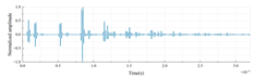 |
 |
 |
| PMMA-LDPE-PTFE | 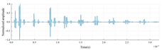 |
 |
 |
| PTFE-PMMA-LDPE | 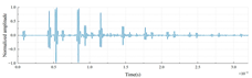 |
 |
 |
| PTFE-LDPE-PMMA | 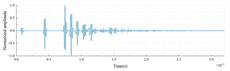 |
 |
 |
| LDPE-PMMA-PTFE | 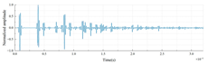 |
 |
 |
| LDPE-PTFE-PMMA | 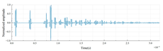 |
 |
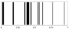 |
Table 3.
Mean Jaccard Index (MJI) Comparison: Noisy vs. Clean Data (SNR=3dB).
| Comparison Data | MJI (%) |
|---|---|
| PMMA-PTFE-LDPE | 99.02 |
| PMMA-LDPE-PTFE | 98.24 |
| PTFE-LDPE-PMMA | 98.71 |
| PTFE-PMMA-LDPE | 98.27 |
| LDPE-PMMA-PTFE | 97.58 |
| LDPE-PTFE-PMMA | 97.40 |
| Mean | 98.20 |
Table 4.
Mean Jaccard Index (MJI) Comparison: Noisy vs. Clean Data with Metal Backing Plate.
| Structural Steel MJI (%) | Aluminum MJI (%) |
|---|---|
| 98.54 | 98.76 |
| 98.31 | 98.24 |
| 98.97 | 98.60 |
| 98.64 | 98.73 |
| 97.17 | 96.98 |
| 97.61 | 97.92 |
| 98.21(mean) | 98.21(mean) |
Table 5.
Calculation content.
| Number of material layers | Cylinder radius | quantity |
|---|---|---|
| 3 | 0.25 | 210 |
| 4 | 0.26 | 840 |
| 5 | 0.27 | 2520 |
Table 6.
Bootstrap Resampling.
| Number of material layers | Lower Bound | Upper Bound |
|---|---|---|
| 3 | 95.67 | 96.11 |
| 4 | 95.03 | 95.28 |
| 5 | 94.46 | 94.60 |
| All | 94.70 | 94.82 |
Disclaimer/Publisher’s Note: The statements, opinions and data contained in all publications are solely those of the individual author(s) and contributor(s) and not of MDPI and/or the editor(s). MDPI and/or the editor(s) disclaim responsibility for any injury to people or property resulting from any ideas, methods, instructions or products referred to in the content. |
© 2025 by the authors. Licensee MDPI, Basel, Switzerland. This article is an open access article distributed under the terms and conditions of the Creative Commons Attribution (CC BY) license (http://creativecommons.org/licenses/by/4.0/).
Copyright: This open access article is published under a Creative Commons CC BY 4.0 license, which permit the free download, distribution, and reuse, provided that the author and preprint are cited in any reuse.


