
Submitted:
24 February 2025
Posted:
25 February 2025
You are already at the latest version
Abstract
Mitral valve regurgitation is among the most prevalent valvular heart diseases and increases with age. Percutaneous therapy has emerged for the management of mitral regurgitation in high surgical risk patients. However, long-term consequences of these interventions are still not fully understood due to their novelty and the difficulty to develop a strategy specific to the patient’s anatomy and/or pathology. To optimize these outcomes, an in vitro patient-specific approach could provide important insights for the most suitable strategy to use according to the patient profile. To ensure reliability of this in vitro approach, aim of this study was to reproduce the physiological behavior of the healthy native mitral valve for future applications. To do so, different silicon combinations reproducing physiological anatomy of healthy mitral valve were developed and tested under physiological hemodynamic conditions in a cardiac simulator. The hemodynamic and biomechanical behaviors of each mitral valve model were analyzed and compared to the physiological values provided in the literature. This study identified EcoFlex 00-50 and DragonSkin 10 (Smooth-On Inc, USA) as the optimal silicon combination resulting in physiological strain values and hemodynamic parameters. These findings could be useful for future patient-specific applications, helping in the optimization of percutaneous mitral valve therapy.
Keywords:
Mitral valve
; In vitro
; Biomechanics
; Silicon
; Modeling
; 3D printing
1. Introduction
Mitral valve regurgitation is one of the most common valvular diseases [1] affecting 2% of the population worldwide [2,3] and over 10% of the population aged over 70 years [4]. Characterized by a retrograde flow from the left ventricle to the left atrium during the ventricular systole, which is due to an insufficient coaptation of the mitral valve leaflet, mitral regurgitation can induce ventricular and auricular remodeling, high pulmonary arterial pressure and ultimately leads to heart failure and death [5,6]. Until now, no pharmacotherapy has been proven to be efficient to treat this condition and the only option is to repair or replace the failed mitral valve generally through an open-heart surgery [7,8]. However, due to high surgical risk, about half of patients with severe mitral regurgitations are denied from surgical therapy [9]. To address this issue, numerous percutaneous procedures using different devices have been developed over the past decade, enabling the repair or replacement of the mitral valve [10], such as Transcatheter Edge-to-Edge Repair (TEER) [11], Annuloplasty [12] or Transcatheter Mitral Valve Replacement (TMVR) [13]. Nevertheless, due to the novelty of these procedures, the long-term hemodynamics and biomechanical outcomes remain unknown. In vitro studies can help to overcome these issues by providing a better understanding of mechanical and hemodynamic outcomes in a controlled and reproducible environment allowing to collect a wide spectrum of patient-specific data and test different strategies that might be impossible to test in vivo. Indeed, previous in vitro studies have been able to report hemodynamic consequences of surgical or percutaneous treatments by using porcine or bovine physiologic or pathophysiologic mitral valve model [14,15,16]. Nevertheless, due to the heterogeneity of mitral valve pathologies, the strategy for treatment of mitral valve disease is shifting towards an individualized approach and could benefit from in vitro patient-specific applications. Realistic models mimicking patient-specific conditions have been created by successfully replicating the anatomical and hemodynamic properties of the patient's mitral valve in different studies [17,18,19]. However, the models that have been created are still attempting to reproduce correctly the physiological behavior of a healthy mitral valve. The goal of this study is to enhance the understanding of both healthy and pathological mitral valves by reproducing precisely their anatomical properties and testing them under controlled conditions. In the future, these results can be used to better understand the biomechanical and hemodynamic outcomes of percutaneous intervention in a patient-specific approach and therefore provide important insight on procedure planning and optimization and on its long-term durability.
2. Materials and Methods
The present study investigates the behavior induced by 12 different custom-made silicon mitral valves tested under normal hemodynamic conditions. The silicon mitral valves were fabricated using a 3D-printed mold filled with different layers of silicon. To determine the silicon combination that results in the most physiological behavior, anatomical, hemodynamic and biomechanic responses have been analyzed using a cardiac simulator.
2.1. Mitral Valve Mold
To ensure a physiological reproduction of the mitral valve anatomy, the mitral valve models were based on the anatomy of the Lifelike mitral valve (Lifelike BioTissue Inc., ON, CA). While the hydrogel mitral valve is typically used by surgeons for surgical training in repairing P2 prolapse, in this study a healthy mitral valve model previously developed by the company was used as reference. The Lifelike valve was imaged with desktop micro-CT scanner (NanoScan PET-CT, Mediso) and the high-resolution images were imported into 3D Slicer [20] for segmentation (Figure 1a). The finalized model was imported into MeshMixer (Autodesk Inc., CA, USA) to create a negative mold. The mold was then 3D printed (Figure 1b) with Lulzbot Taz Pro Dual Extruder printer (Lulzbot, ND, USA) using NinjaFlex material (NinjaTek 3D, PA, USA) which elasticity allowed for the easy extraction of dried silicon mitral valve models.
2.2. Silicon Mitral Valve
To guarantee a homogenous curing of the silicon combinations (Table 1), the 3D printed molds were covered with silicon layer by layer using a specific number of layers for each type of silicon to obtain a predefined leaflet thickness. Leaflet thickness of healthy native mitral valve ranges from 1 to 2 mm [21], therefore three custom-made mitral valve models were created with a leaflet thickness of 1, 1.5 and 2 mm. The chordae tendinae were replicated using six de-braided strings (100% polyester, Gütterman GmbH, Germany) per valve (Figure 1c) inserted within silicon’s layers, ensuring the tension during cardiac cycle. Each string was de-braided and divided into three, providing 18 points of tensile force applied on mitral valve’s leaflets. The silicon models were then left to dry for several hours before being removed from their molds (Figure 1d).
2.3. Materials Properties
In this study, four different silicon elastomers (i.e., EcoFlex 00-30 (EF30), EcoFlex 00-50 (EF50), DragonSkin 10 Very Fast (DS10), DragonSkin 20 (DS20) (Smooth-On Inc., Easton, PA, USA)) with different mechanical properties were used to create mitral valve models and were compared to identify which one most closely mimics the tissue of the healthy native mitral valve. Additionally, different combinations of theses elastomers were used to recreate the leaflet’s microstructure mimicking elastin and collagen fibers within the different layers of the leaflet as each layer contributes to ensure optimal hemodynamic and mechanical environment without any abnormal hemodynamic disturbance. The different combinations are referred in Table 1. The previously cited elastomers (EF30 and DS10) were chosen due to their previous use in literature for in vitro mitral implications. Indeed, EF30 has already been used for its cutting and resection feeling close to those experienced by surgeons in surgical procedures [22]. Ginty et al.,[17], made the mitral valve models using EcoFlex 00-30 due to its realistic leaflet flexibility and ultrasound imaging. However, in this study, gauzes needed to be placed between layers to improve tensile strength of the silicon leaflets. Another study by Premyodhin et al. [23] tested DragonSkin 10 for its flexibility and tearing behavior. According to the surgical consultant, the tearing behavior was suitable for reproducing cutting suturing while maintaining a realistic flexibility. For the purpose of this study, EcoFlex 00-50 and DragonSkin 20 were added to the tested elastomers as their provided different Shore-Hardness or other material properties useful for matching closely the mitral valve properties. Young’s Modulus of each elastomer was evaluated by equi-biaxial testing with a maximal force applied of 0.5N at a loading speed of 0.01mm/s. Material properties found in the literature [24,25,26,27,28,29] and obtained by equi-biaxial testing are summarized in Table 2.
2.4. In Vitro Testing
In vitro testing was performed using a double activation left heart duplicator system[30]. This system includes anatomically shaped and deformable silicons models of left ventricle and atrium supplied by four pulmonary veins. Both cavities are surrounded by liquid and are activated by piston-pumps (Vivitro Inc., Victoria, Canada) controlled using LabVIEW8.2 (National Instruments, Texas, USA). The duplicator system is designed to maintain its temperature at 37°C and is filled with a mixture of glycerin and water, which results in a fluid with the same viscosity as blood (3.8 - 4.0 cP). Transvalvular flow was measured with an electromagnetic flowmeter (Model 501, Carolina Medical Electronics Inc., East Bend, USA, accuracy ±1% maximum full scale) positioned immediately before the valve and averaged over 100 cycles. Pressures in the left atrium, left ventricle and the aortic root were recorded by micro-tip pressure catheters (Millar catheter and signal conditioning unit, Millar Instruments, Houston, TX, accuracy ± 0.5% maximum full scale). Doppler echocardiographic measurements were performed using Philips iE33 (Philips, Eindhoven, Netherlands). The transvalvular flow velocities, mean pressure gradient (MPG), Diastolic Filling Period (DFP) and mitral Velocity-Time Integral (VTI) were measured ten times per condition by continuous-wave Doppler. The mitral valve area (MVA) was estimated using Gorlin formula [31].
CO = Cardiac Output (mL/min)
HR = Heart Rate (bpm)
Each of the silicon mitral valves was tested under experimental conditions replicating the heart rate, the stroke volume (SV) and mean aortic pressure of a healthy individual (70 bpm, 70 ml and 100 mmHg respectively). To measure stress-strain repartition and leaflet displacement of the mitral valve models, a non- contact optical 3D Digital Image Correlation method (DIC) was conducted with commercial system VIC3D (Correlated Solutions, Inc). Two high-speed video cameras (1,000 img/sec) (FASTCAM SA3; Photron, Inc., San Diego, CA, USA), equipped with 105 mm lenses (EF 24 Reflex lenses; Sigma Corporation, Kanagawa, Japan) were used to record the leaflet motion. Finally, the mitral valve models were tattooed with black tissue dye (Killer Ink Tattoo., UK) in order to create a fine speckle patterned allowing the use of DIC. This method allows a direct assessment of local, displacements and deformations /strains of the mitral leaflet throughout one cardiac cycle for a better comparison of mechanical properties of the different mitral valves created in this study. Finally, evaluation of the geometric diastolic orifice area (GOA) was done using custom-coded Matlab program (The Mathworks Inc., MA, USA) coupled with the video of leaflet motion acquired by the high-speed cameras.
2.5. Statistical Analysis
Continuous variables were presented as mean values ± sd and were compared using Student t-test (p-value < 0.05 considered statistically significant).
3. Results
3.1. Anatomical Properties
The first step in evaluating the characteristics of reproduced mitral valves (Figure 2) was evaluating their anatomical characteristics. The custom-made mitral valves were composed of a mitral annulus with thickness of 4 mm, surrounding the leaflet area and replicating an elliptic shape with the antero-posterior diameter smaller than the commissural length (Figure 2a, p<0.001) as observed in in vivo studies [32]. The silicon mitral valves consisted of two leaflets, anterior and posterior, each divided into three leaflet segments: A1, A2, A3, P1, P2, P3 as illustrated in Figure 2. To ensure the physiological anatomy, the anterior leaflet was longer than the posterior (Figure 2b, p<0.001) with the P2 segment being longer than the P1 (p<0.001) and longer than P3 (p<0.001) [33]. Six de-braided strings were placed between two distinct layers of silicon, generating a simplified representation of chordae tendineae and therefore allowing the tensile applications on the free edge of leaflet, preventing them to flail into the left atrium during the systolic cardiac phase. Leaflet thickness was set firstly at 1.5 mm for each model, then only the valves that passed the hemodynamical properties test were replicated with 1 and 2 mm for evaluation of thickness impact on mitral valves' hemodynamics.
3.2. Hemodynamical Properties
Following validation of the physiological anatomical reproductions of native mitral valves, each silicon mitral valve model was tested under physiological conditions to study their hemodynamic behavior (Table 3). Continuous doppler acquisition demonstrated that every valve induced a physiological response, with E and A waves, which are characteristic of healthy native mitral flow. Only one model (DS10EF30 (=V9)) had a regurgitant orifice area of 0.20 cm², consistent with mild to moderate regurgitation in clinical guidelines [34]. All the other silicon mitral valves had none or trace mitral regurgitation. Based on clinical guidelines (Table 4) [35,36], three silicon models (EF30(=V1), EF30DS10(=V5) and EF50DS10(=V7)) were able to reproduce healthy physiological hemodynamic conditions with a MVA > 4 cm², a GOA > 4cm², MPG ≤ 2mmHg, Vmax < 1.5 cm/s, VTI < 31cm and a DVI <2.2 (Table 3).
3.3. Leaflet Thickness
Based on hemodynamic results, the silicon mitral valves V1, V5 and V7 were selected to study the influence of leaflet thickness on valve hemodynamic parameters. Three different thicknesses (1, 1.5 and 2 mm) of leaflets for each valve were tested under physiological conditions in the cardiac dual-activation cardiac simulator. MVA, GOA and MPG were analyzed for each silicon mitral valve (Figure 3, Table 4). All the silicon mitral valves induced a mitral flow profile characterized by physiological E and A flow waves except for the valve V1 at 1mm due to its high elastic composition. As shown in Figure 3 the largest GOA and MVA (p<0.005) for each combination of silicon mitral valve was obtained when the leaflet thickness was fixed at 1.5 mm. Similar results were found when analyzing the MPG, the leaflet thickness of 1.5mm was the only one inducing value under 2 mmHg.
3.4. Biomechanical Properties
To ensure the physiological reproduction of the native mitral valve the next step was to validate the biomechanical properties of the three selected silicon mitral valves (V1, V5 and V7). Leaflet displacement evaluation is necessary to ensure that prolapse behavior is not present, even though the regurgitant orifice area has been assessed for these valves before. The leaflet prolapse is defined as displacement of leaflet tissue into left atrium, more than 2 mm past the mitral annular plane during the systolic cardiac phase. After the visualization of the silicon mitral valves during the mid-systolic cardiac phase (Figure 4), it appeared that the V1 valve caused a consistent A3/P3 prolapse which prevented it from further analysis using the DIC process.
Even though V5 and V7 silicon mitral valves seemed to present a non-prolapsing behavior, the displacement past the mitral annular plane (Z displacement) of each leaflet segment was analyzed. As shown in Figure 5 the Z displacement of each leaflet segment was higher for the V5 valve compared to V7 valve or to the Lifelike mitral valve model (p<0.005). For both silicon mitral valves, the highest leaflet displacement was found in A2 segment. However, the Z displacement was significantly higher for the V5 valve which induced a slight leaflet prolapse (Figure 5, p<0.001).
The accuracy for the DIC was 0.013 pixels. The major (E1) and minor (E2) principal strains were analyzed during systolic cardiac phase. Positive signs in strain describe tension and negative signs the compression. The highest strains are mainly localized on A3/P3 segment for the Lifelike model and on the coaptation line for the V7 valve whereas the V5 seemed to provide a homogenous strain distribution throughout the entire leaflet surface (Figure 6). Besides the strain repartition, the strain intensity on each leaflet segment shown that highest values of major principal strains were indeed induced by the A3/P3 segment on Lifelike model (Figure 7) along with minor principal strain values (Figure 8). Regarding V5 and V7 silicon mitral valves, there weren’t any leaflet segment inducing prominent strain as suspected. Finally, average major principal strains were significantly lower on V7 silicon whole leaflet surface compared to strains induced by the V5 and Lifelike mitral valve (Anterior Leaflet (AL): 11.3%, Posterior Leaflet (PL):12.0%, Total: 12.0% vs AL: 26.0%, PL:25.0%, Total: 25.0% vs AL: 23.0%, PL:24.0%, Total: 24.0% respectively, p<0.001).
4. Discussion
In this study, we sought to create a silicon model that reproduces the physiological behavior of a healthy native mitral valve to fulfill the need for realistic models that could then be applied for testing the different types of mitral valve percutaneous procedures and devices. The hydrogel mitral valve featured great shape fidelity but would not allow a rapid patient-specific anatomy reproduction and therefore it might be an expensive alternative for testing percutaneous devices. Although previous studies have demonstrated the usefulness of silicon for mimicking the anatomy of the human mitral valve [18,39] or the sensation of suture feeling during mitral valve surgical training [23,40], only few studies examined their capabilities to reproduce the hemodynamic behavior of the native mitral valve. Previous studies investigated the hemodynamic outcomes of mitral valve interventions in pulsed duplicator system [17,19,41], but to our knowledge, the physiological behavior of a healthy mitral valve has not been successfully reproduced yet. Hence the goal of this study was to reproduce rheological and hemodynamic behavior of a healthy mitral valve by testing and comparing different silicones (and their combinations) used in previous literature[17,22,23] in order to provide a framework for future patient-specific studies reproducing the mitral valve behavior.
The main finding of this study is that silicon combination EF50DS10 (=V7) was able to replicate the anatomical features of a healthy mitral valve while inducing a normal physiological hemodynamic behavior. Indeed, the EF50DS10 silicon mitral valve with a thickness of 1.5mm achieved MVA > 4cm2, GOA > 4cm2, and MPG ≤ 2mmHg, characteristic of a physiological hemodynamic function. Regarding the biomechanical performance, this silicon combination was one of the few providing a GROA < 0.20 cm² and a prolapsus < 2mm, indicating a non-pathological behavior. Finally, its systolic leaflet strain (≈10%) was comparable to strains measured in vivo [42,43]. The systolic strain induced in the silicon mitral valve was slightly higher compared to in vivo study performed by El-Tallawi et al (AL: 11.3%, PL:12.0%, Total: 12.0% vs. AL: 7.6%, PL: 9.3%, Total: 8.5% respectively), but this could be explained by the non-saddle shape of the mitral annulus of the Lifelike mitral valve model and the simplified configuration of the chordae. Indeed, the complex form of the mitral annulus and the attachment of the chordae on each leaflet are known for reducing leaflet stress and strain [44,45]. While aim of this study was focused on comparing different leaflet silicon combinations, future studies could benefit from adding chordae to reduces leaflet strain. However, adding chordae or increasing their tension could lead to a new hemodynamic behavior. Indeed, the influence of chordae tension plays a key role in leaflet opening and closing behavior, as well as in hemodynamic and biomechanic response. While the reproducibility was achieved by these silicon models, rheological behavior can only be reproduced using identical tension on the chordae (Supplementary Data 1). Finally, reproducing the saddle-shaped annulus of the native mitral valve could also prevent leaflet prolapse and higher strain.
In summary, the purpose of the current study was to provide a physiological model of a native healthy mitral valve to respond to the deficiencies of the current mitral valve models used in in vitro experiments. This study offers a low-cost, simple, and customizable process to develop a healthy/pathological generic or patient-specific mitral valve. However, despite its material stability and 24-month shelf-life, the authors recommend using the silicon mitral valve within the year after its creation to assure the data reliability.
While this research focused on the development of healthy mitral valves, results from the different silicon combination tested in this study could be useful to develop and understand different mitral valve dysfunction. Indeed, even if every silicon combination was able to reproduce anatomical features of a healthy mitral valve, physiological hemodynamic function was induced only by three mitral valves (V1, V5 and V7) with a leaflet thickness of 1.5mm. Based on these results, stenotic behavior could be reproduced using the combination V10, V11 and/or V3. The silicone combination EF30 could reproduce the leaflet prolapsus resulting from an early fibroelastic deficiency and varying leaflet thickness could also be interesting for inducing different pathological behavior. Indeed, the V1 silicon combination with 1mm leaflet thickness induced a Barlow-type behavior, which represents a challenging clinical entity to manage.
This study provides evidence of the reproduction of physiological mitral valve behavior which could be helpful for future research focused on understanding the effects, outcomes, and long-term durability of percutaneous interventions and devices. Indeed, further investigation into the development of in vitro mitral valve could lead toward the reproduction of patient-specific interventions leading to optimization of the planning of the interventions. Defining the connection between hemodynamic and mechanical parameters could be crucial for optimizing the efficiency of the treatment by highlighting the most suitable device to use with regards of the size, number or type depending on the patient’s specific anatomy and disease etiology. The characterization of these optimized associations has the potential to enhance the quality of life for patients and the devices durability while reducing the risk of surgical reintervention.
5. Conclusions
In conclusion, the silicon combination of EcoFlex 00-50 and DragonSkin 10 with a thickness of 1.5mm enables the closest reproduction of a physiological anatomic, hemodynamic and biomechanical behavior of a healthy mitral valve. The results of this study provide important new insights on the optimal silicon combination for reproducing patient-specific physiological and pathological mitral valves undergoing percutaneous interventions, resulting in a higher level of reliability between in vitro and in vivo research. Further investigation into the behavior of silicon combination could improve the ability to reproduce pathophysiological behavior of native mitral valve. This progress may pave the way for a patient-specific approach leading toward an individualization of the percutaneous treatment of the mitral valve by tailoring the procedural strategy on the etiology and anatomy of the individual patient.
Author Contributions
Conceptualization, K.D. and V.S.; methodology, K.D and V.S.; software, K.D; validation, K.D., V.S., R.R, E.S and P.P.; formal analysis, K.D.; investigation, K.D.; resources, V.S and P.P.; data curation, K.D.; writing—original draft preparation, K.D.; writing—review and editing, K.D., V.S., R.R, E.S, N.C and P.P.; visualization, K.D.; supervision, V.S., R.R, E.S and P.P; project administration, V.S.; funding acquisition, V.S. and P.P. All authors have read and agreed to the published version of the manuscript.
Funding
This research received no external funding
Acknowledgments
The authors would like to thank the Laboratoire de Biomécanique Appliquée (France) and particularly Dr. Evin for performing all the equibiaxial test helping us understanding the mechanical properties of the silicones used.
Conflicts of Interest
Pr. Philippe Pibarot reports research grants from Edwards Lifesciences, Medtronic, and Pi-Cardia. The funders had no role in the design of the study; in the collection, analyses, or interpretation of data; in the writing of the manuscript; or in the decision to publish the results. All other authors have no conflict of interest to disclose.
Abbreviations
The following abbreviations are used in this manuscript:
| TEER | Transcatheter Edge-to-Edge-Repair |
| TMVR | Transcatheter Mitral Valve Replacement |
| EF30 | EcoFlex 00-30 |
| EF50 | EcoFlex 00-50 |
| DS10 | DragonSkin 10 |
| DS20 | DragonSkin 20 |
| MPG | Mean Pressure Gradient |
| DFP | Diastolic Filling Pressure |
| VTI | Velocity-Time Integral |
| Vmax | Maximal Velocity |
| DVI | Dimensionless Valve Index |
| MVA | Mitral Valve Area |
| CO | Cardiac Output |
| HR | Heart Rate |
| SV | Stroke Volume |
| DIC | Digital Image Correlation |
| GOA | Geometric Orifice Area |
| GROA | Geometric Regurgitant Orifice Area |
| AL | Anterior Leaflet |
| PL | Posterior Leaflet |
References
- Coffey, S.; Roberts-Thomson, R.; Brown, A.; Carapetis, J.; Chen, M.; Enriquez-Sarano, M.; Zühlke, L.; Prendergast, B.D. Global epidemiology of valvular heart disease. Nat. Rev. Cardiol. 2021, 18, 863–864. [Google Scholar] [CrossRef] [PubMed]
- Iung, B.; Baron, G.; Butchart, E.G.; Delahaye, F.; Gohlke-Barwolf, C.; Levang, O.W.; Tornos, P.; Vanoverschelde, J.-L.; Vermeer, F.; Boersma, E.; et al. A prospective survey of patients with valvular heart disease in Europe : The Euro Heart Survey on Valvular heart Disease. Eur. Heart J. 2003, 24, 1231–1243. [Google Scholar] [CrossRef] [PubMed]
- Freed, L.A.; Levy, D.; Levine, R.A.; Larson, M.G.; Evans, J.C.; Fuller, D.L.; Lehman, B.; Benjamin, E.J. Prevalence and clinical outcome of mitral-valve prolapse. N. Engl. J. Med. 1999, 341, 1–7. [Google Scholar] [CrossRef] [PubMed]
- Nkomo, V.T.; Gardin, J.M.; Skelton, T.N.; Gottdiener, J.S.; Scott, C.G.; Enriquez-Sarano, M. Burden of valvular heart diseases: A population-based study. Lancet 2006, 368, 1005–1011. [Google Scholar] [CrossRef]
- Delling, F.N.; Vasan, R.S. Epidemiology and pathophysiology of mitral valve prolapse: New insights into disease progression, genetics, and molecular basis. Circulation 2014, 129, 2158–2170. [Google Scholar] [CrossRef]
- El Sabbagh, A.; Reddy, Y.N.V.; Nishimura, R.A. Mitral valve regurgitation in the contemporary era: Insights into diagnosis, management, and future directions. JACC Cardiovasc. Imaging 2018, 11, 628–643. [Google Scholar] [CrossRef]
- Baumgartner, H.; Falk, V.; Bax, J.J.; De Bonis, M.; Hamm, C.; Holm, P.J.; Iung, B.; Lancellotti, P.; Lansac, E.; Muñoz, D.R.; et al. 2017 ESC/EACTS guidelines for the management of valvular heart disease: The Task Force for the management of valvular heart disease of the European Society of Cardiology (ESC) and the European Association for Cardio-Thoracic Surgery (EACTS). Eur. Heart J. 2017, 38, 2739–2791. [Google Scholar] [CrossRef]
- Kouris, N.; Ikonomidis, I.; Kontogianni, D.; Smith, P.; Nihoyannopoulos, P. Mitral valve repair versus replacement for isolated non-ischemic mitral regurgitation in patients with preoperative left ventricular dysfunction. A long-term follow-up echocardiography study. Eur. J. Echocardiogr. 2005, 6, 435–442. [Google Scholar] [CrossRef]
- Mirabel, M.; Iung, B.; Baron, G.; Messika-Zeitoun, D.; Detaint, D.; Vanoverschelde, J.L.; Butchart, E.G.; Ravaud, P.; Vahanian, A. What are the characteristics of patients with severe, symptomatic, mitral regurgitation who are denied surgery? Eur. Heart J. 2007, 28, 1358–1365. [Google Scholar] [CrossRef]
- Chan, N.; Dong, T.; Sabbak, N.; Xu, B.; Wang, T.K.M. Contemporary Review of Transcatheter Mitral Valve Interventions for Mitral Regurgitation. Life 2023, 13, 1511. [Google Scholar] [CrossRef]
- Khan, F.; Winkel, M.; Ong, G.; Brugger, N.; Pilgrim, T.; Windecker, S.; Praz, F.; Fam, N. Percutaneous Mitral Edge-to-Edge Repair: State of the Art and a Glimpse to the Future. Front. Cardiovasc. Med. 2019, 6, 122. [Google Scholar] [CrossRef] [PubMed]
- Yildiz, M.; Haude, M.; Sievert, H.; Fichtlscherer, S.; Lehmann, R.; Klein, N.; Witte, K.; Degen, H.; Pfeiffer, D.; Goldberg, S.L. The CINCH-FMR postmarket registry: Real-world long-term outcomes with percutaneous mitral valve repair with the Carillon Mitral Contour System®. Cardiovasc. Revasc. Med. 2024, 60, 35–40. [Google Scholar] [CrossRef] [PubMed]
- Hell, M.M.; Wild, M.G.; Baldus, S.; Rudolph, T.; Treede, H.; Petronio, A.S.; Modine, T.; Andreas, M.; Coisne, A.; Duncan, A.; et al. Transapical Mitral Valve Replacement: 1-Year Results of the Real-World Tendyne European Experience Registry. JACC Cardiovasc. Interv. 2024, 17, 648–661. [Google Scholar] [CrossRef] [PubMed]
- Zhan-Moodie, S.; Xu, D.; Suresh, K.S.; He, Q.; Onohara, D.; Kalra, K.; Guyton, R.A.; Sarin, E.L.; Padala, M. Papillary muscle approximation reduces systolic tethering forces and improves mitral valve closure in the repair of functional mitral regurgitation. JTCVS Open 2021, 7, 91–104. [Google Scholar] [CrossRef]
- Paulsen, M.J.; Cuartas, M.M.; Imbrie-Moore, A.; Wang, H.; Wilkerson, R.; Farry, J.; Zhu, Y.; Ma, M.; MacArthur, J.W.; Woo, Y.J. Biomechanical engineering comparison of four leaflet repair techniques for mitral regurgitation using a novel 3-dimensional-printed left heart simulator. JTCVS Tech. 2021, 10, 244–251. [Google Scholar] [CrossRef]
- Park, M.H.; van Kampen, A.; Melnitchouk, S.; Wilkerson, R.J.; Nagata, Y.; Zhu, Y.; Wang, H.; Pandya, P.K.; Morningstar, J.E.; Borger, M.A.; et al. Native and Post-Repair Residual Mitral Valve Prolapse Increases Forces Exerted on the Papillary Muscles: A Possible Mechanism for Localized Fibrosis? Circ. Cardiovasc. Interv. 2022, 15, e011928. [Google Scholar] [CrossRef]
- Ginty, O.; Moore, J.; Xia, W.; Bainbridge, D.; Peters, T. Patient-specific indirectly 3D printed mitral valves for pre-operative surgical modelling. Proceedings of Medical Imaging 2017: Image-Guided Procedures, Robotic Interventions, and Modeling; pp. 316–330.
- Ginty, O.K.; Moore, J.T.; Eskandari, M.; Carnahan, P.; Lasso, A.; Jolley, M.A.; Monaghan, M.; Peters, T.M. Dynamic, patient-specific mitral valve modelling for planning transcatheter repairs. Int. J. Comput. Assist. Radiol. Surg. 2019, 14, 1227–1235. [Google Scholar] [CrossRef]
- Mashari, A.; Knio, Z.; Jeganathan, J.; Montealegre-Gallegos, M.; Yeh, L.; Amador, Y.; Matyal, R.; Saraf, R.; Khabbaz, K.; Mahmood, F. Hemodynamic Testing of Patient-Specific Mitral Valves Using a Pulse Duplicator: A Clinical Application of Three-Dimensional Printing. J. Cardiothorac. Vasc. Anesth. 2016, 30, 1278–1285. [Google Scholar] [CrossRef]
- Fedorov, A.; Beichel, R.; Kalpathy-Cramer, J.; Finet, J.; Fillion-Robin, J.C.; Pujol, S.; Bauer, C.; Jennings, D.; Fennessy, F.; Sonka, M.; et al. 3D Slicer as an image computing platform for the Quantitative Imaging Network. Magn. Reson. Imaging 2012, 30, 1323–1341. [Google Scholar] [CrossRef]
- Grande-Allen, K.J.; Barber, J.E.; Klatka, K.M.; Houghtaling, P.L.; Vesely, I.; Moravec, C.S.; McCarthy, P.M. Mitral valve stiffening in end-stage heart failure: Evidence of an organic contribution to functional mitral regurgitation. J. Thorac. Cardiovasc. Surg. 2005, 130, 783–790. [Google Scholar] [CrossRef]
- Engelhardt, S.; Sauerzapf, S.; Preim, B.; Karck, M.; Wolf, I.; De Simone, R. Flexible and comprehensive patient-specific mitral valve silicone models with chordae tendineae made from 3D-printable molds. Int. J. Comput. Assist. Radiol. Surg. 2019, 14, 1177–1186. [Google Scholar] [CrossRef] [PubMed]
- Premyodhin, N.; Mandair, D.; Ferng, A.S.; Leach, T.S.; Palsma, R.P.; Albanna, M.Z.; Khalpey, Z.I. 3D printed mitral valve models: Affordable simulation for robotic mitral valve repair. Interact. Cardiovasc. Thorac. Surg. 2018, 26, 71–76. [Google Scholar] [CrossRef] [PubMed]
- Vaicekauskaite, J.; Mazurek, P.; Vudayagiri, S.; Skov, A.L. Mapping the mechanical and electrical properties of commercial silicone elastomer formulations for stretchable transducers. J. Mater. Chem. C 2020, 8, 1273–1279. [Google Scholar] [CrossRef]
- Korossis, S. Structure-Function Relationship of Heart Valves in Health and Disease.
- Kenry, Y.J.C.; Lim, C.T. Emerging flexible and wearable physical sensing platforms for healthcare and biomedical applications. Microsyst. Nanoeng. 2016, 2, 16043. [Google Scholar] [CrossRef]
- Lavazza, J.; Contino, M.; Marano, C. Strain rate, temperature and deformation state effect on Ecoflex 00-50 silicone mechanical behaviour. Mech. Mater. 2023, 178, 104560. [Google Scholar] [CrossRef]
- Marechal, L.; Balland, P.; Lindenroth, L.; Petrou, F.; Kontovounisios, C.; Bello, F. Toward a Common Framework and Database of Materials for Soft Robotics. Soft Robot. 2020, 8, 284–297. [Google Scholar] [CrossRef]
- Barber, J.E.; Kasper, F.K.; Ratliff, N.B.; Cosgrove, D.M.; Griffin, B.P.; Vesely, I. Mechanical properties of myxomatous mitral valves. J. Thorac. Cardiovasc. Surg. 2001, 122, 955–962. [Google Scholar] [CrossRef]
- Tanné, D.; Bertrand, E.; Kadem, L.; Pibarot, P.; Rieu, R. Assessment of left heart and pulmonary circulation flow dynamics by a new pulsed mock circulatory system. Exp. Fluids 2010, 48, 837–850. [Google Scholar] [CrossRef]
- Gorlin, R.; Dexter, L. Hydraulic formula for the calculation of the cross-sectional area of the mitral valve during regurgitation. Am. Heart J. 1952, 43, 188–205. [Google Scholar] [CrossRef]
- Robinson, S.; Ring, L.; Augustine, D.X.; Rekhraj, S.; Oxborough, D.; Harkness, A.; Lancellotti, P.; Rana, B. The assessment of mitral valve disease: A guideline from the British Society of Echocardiography. Echo Res. Pract. 2021, 8, G87–G136. [Google Scholar] [CrossRef] [PubMed]
- Oliveira, D.; Srinivasan, J.; Espino, D.; Buchan, K.; Dawson, D.; Shepherd, D. Geometric description for the anatomy of the mitral valve: A review. J. Anat. 2020, 237, 209–224. [Google Scholar] [CrossRef] [PubMed]
- Zoghbi, W.A.; Adams, D.; Bonow, R.O.; Enriquez-Sarano, M.; Foster, E.; Grayburn, P.A.; Hahn, R.T.; Han, Y.; Hung, J.; Lang, R.M.; et al. Recommendations for non invasive evaluation of native valvular regurgitation: A report from the American Society of Echocardiography developed in collaboration with the Society for Cardiovascular Magnetic Resonance. J. Am. Soc. Echocardiogr. 2017, 30, 303–371. [Google Scholar] [CrossRef] [PubMed]
- Zoghbi, W.A.; Jone, P.-N.; Chamsi-Pasha, M.A.; Chen, T.; Collins, K.A.; Desai, M.Y.; Grayburn, P.; Groves, D.W.; Hahn, R.T.; Little, S.H.; et al. Guidelines for the Evaluation of Prosthetic Valve Function With Cardiovascular Imaging: A Report From the American Society of Echocardiography Developed in Collaboration With the Society for Cardiovascular Magnetic Resonance and the Society of Cardiovascular Computed Tomography. J. Am. Soc. Echocardiogr. 2024, 37, 2–63. [Google Scholar] [CrossRef]
- Grayburn, P.A.; Weissman, N.J.; Zamorano, J.L. Quantitation of mitral regurgitation. Circulation 2012, 126, 2005–2017. [Google Scholar] [CrossRef]
- Jawad, I.A.; Ghali, M.; Brown, R.; Sohn, Y.H. Pressure-flow relations across the normal mitral valve. Am. J. Cardiol. 1987, 59, 915–918. [Google Scholar] [CrossRef]
- Singh, B.; Mohan, J.C. Atrioventricular valve orifice areas in normal subjects: Determination by cross-sectional and Doppler echocardiography. Int. J. Cardiol. 1994, 44, 85–91. [Google Scholar] [CrossRef]
- Yang, Y.; Wang, H.; Song, H.; Hu, Y.; Gong, Q.; Xiong, Y.; Liu, J.; Ren, W.; Zhou, Q. Morphological Evaluation of Mitral Valve Based on Three-dimensional Printing Models: Potential Implication for Mitral Valve Repair. BIO Integr. 2021, 2, 143–151. [Google Scholar] [CrossRef]
- Engelhardt, S.; Sauerzapf, S.; Al-Maisary, S.; Karck, M.; Preim, B.; Wolf, I.; Simone, R. Elastic Mitral Valve Silicone Replica Made from 3D-Printable Molds Offer Advanced Surgical Training; 2018. [Google Scholar]
- Yang, Y.; Wang, H.; Song, H.; Hu, X.; Hu, R.; Cao, S.; Guo, J.; Zhou, Q. A soft functional mitral valve model prepared by three-dimensional printing as an aid for an advanced mitral valve operation. Eur. J. Cardiothorac. Surg. 2022, 61, 877–885. [Google Scholar] [CrossRef]
- El-Tallawi, K.C.; Zhang, P.; Azencott, R.; He, J.; Herrera, E.L.; Xu, J.; Chamsi-Pasha, M.; Jacob, J.; Lawrie, G.M.; Zoghbi, W.A. Valve strain quantitation in normal mitral valves and mitral prolapse with variable degrees of regurgitation. JACC Cardiovasc. Imaging 2021, 14, 1099–1109. [Google Scholar] [CrossRef]
- Zekry, S.B., et al., Patient-Specific Quantitation of Mitral Valve Strain by Computer Analysis of Three-Dimensional Echocardiography. Circulation: Cardiovascular Imaging, 2016. 9(1): p. e003254.
- Jimenez, J.H.; Liou, S.W.; Padala, M.; He, Z.; Sacks, M.; Gorman, R.C.; Gorman, J.H., 3rd; Yoganathan, A.P. A saddle-shaped annulus reduces systolic strain on the central region of the mitral valve anterior leaflet. J. Thorac. Cardiovasc. Surg. 2007, 134, 1562–1568. [Google Scholar] [CrossRef] [PubMed]
- Chen, L.; May-Newman, K. Effect of strut chordae transection on mitral valve leaflet biomechanics. Ann. Biomed. Eng. 2006, 34, 917–926. [Google Scholar] [CrossRef] [PubMed]
Figure 1.
Development processus of silicon mitral valves; a) Lifelike 3D model, b) 3D printed mold, c) Chordae added between silicon layers, d) Final silicon mitral valve.
Figure 1.
Development processus of silicon mitral valves; a) Lifelike 3D model, b) 3D printed mold, c) Chordae added between silicon layers, d) Final silicon mitral valve.
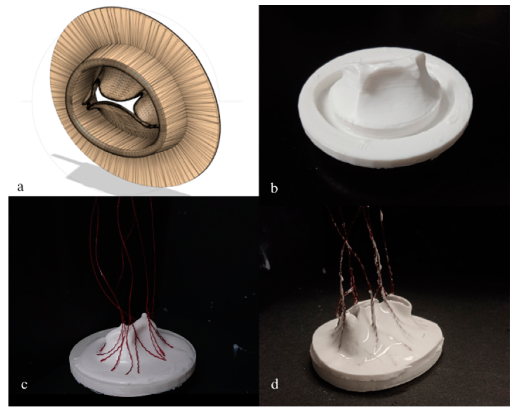
Figure 2.
Anatomical characteristics of silicon mitral valves on (a) surgical view, (b) ventricular view. Different segments of the mitral valve anatomy were measured on different view. Surgical view (a): long axis diameter (red line), short axis diameter (pink line), annulus thickness (green arrow). Ventricular view (b): Anterior leaflet length (beige arrow), P3 length (green arrow), P2 length (blue arrow), P3 length (grey arrow).
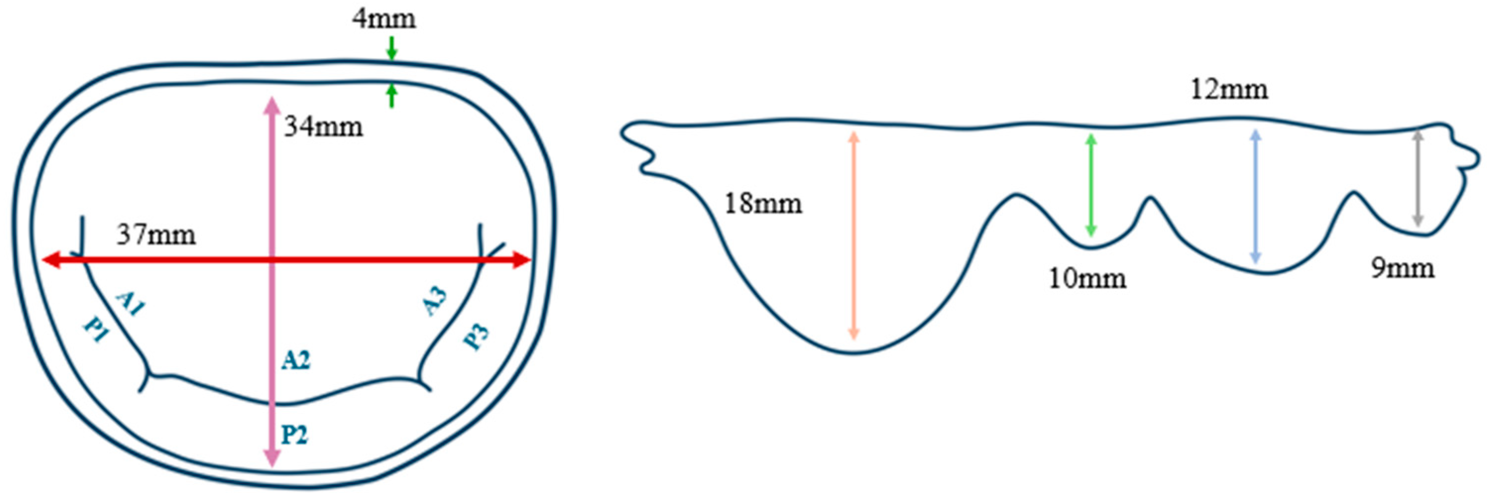
Figure 3.
Hemodynamical parameters depending on leaflet thickness (a) GOA, (b) MPG. Comparison of hemodynamical behavior induced by three chosen silicon mitral valves with three different leaflet thickness. (EF30 = V1, EF30DS10 = V5, EF50DS10 = V7). *: p<0.005, **: p<0.001.
Figure 3.
Hemodynamical parameters depending on leaflet thickness (a) GOA, (b) MPG. Comparison of hemodynamical behavior induced by three chosen silicon mitral valves with three different leaflet thickness. (EF30 = V1, EF30DS10 = V5, EF50DS10 = V7). *: p<0.005, **: p<0.001.
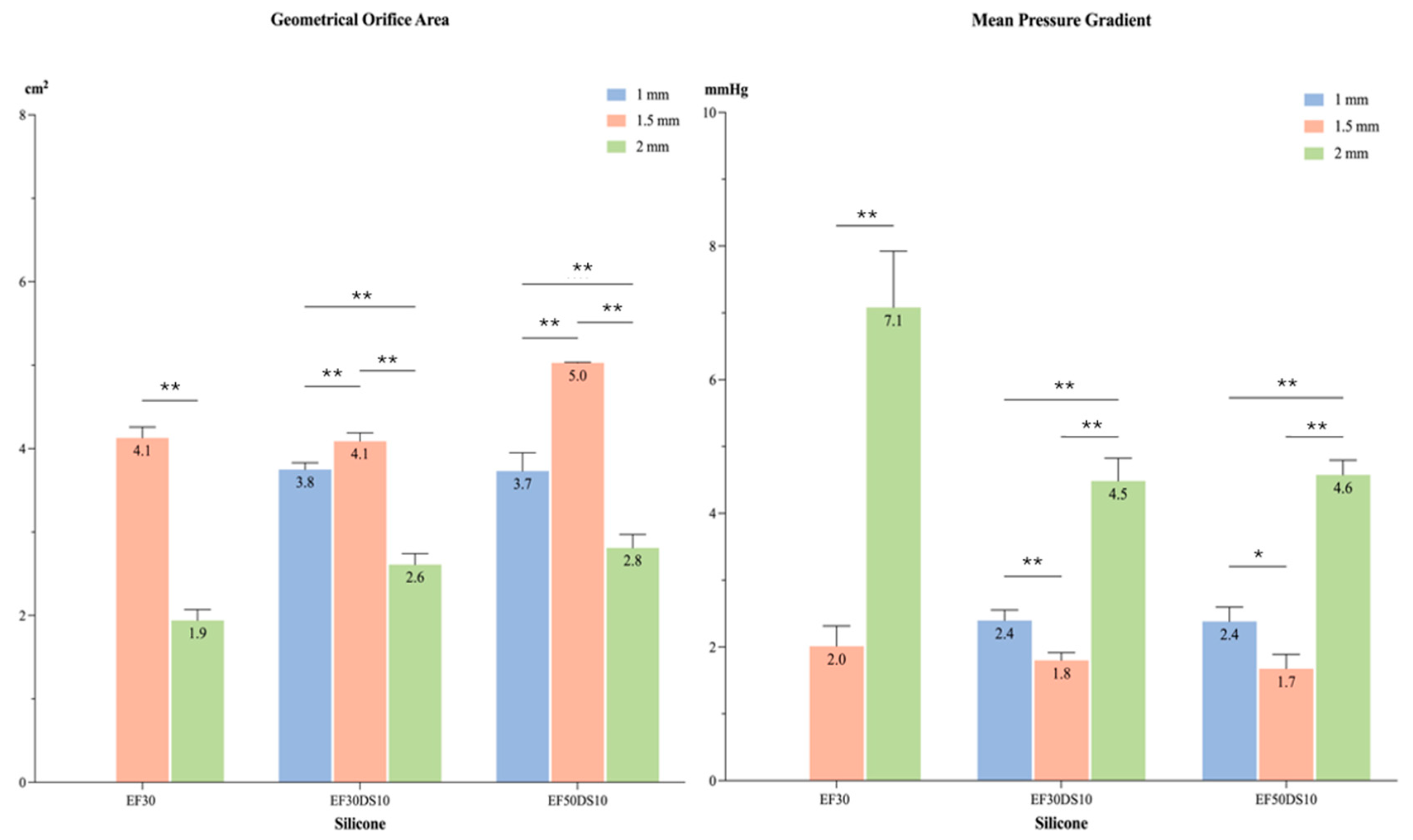
Figure 4.
Mid-systolic closing of silicon mitral valves (a) V1, (b) V5, (c) V7. Three silicons mitral valve inducing the most physiological behavior were analyzed using high-speed video cameras for comparing their rheological behavior during systolic cardiac phase. .
Figure 4.
Mid-systolic closing of silicon mitral valves (a) V1, (b) V5, (c) V7. Three silicons mitral valve inducing the most physiological behavior were analyzed using high-speed video cameras for comparing their rheological behavior during systolic cardiac phase. .
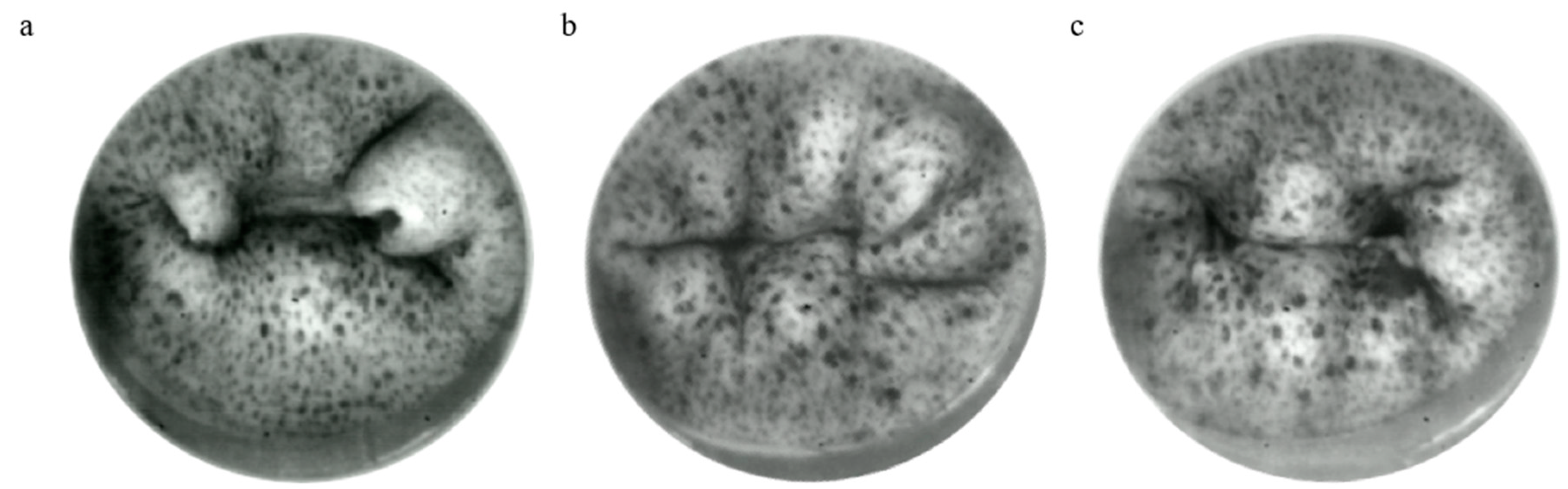
Figure 5.
Leaflet segment displacement (mm) during systolic phase. Leaflet Z displacement during systolic cardiac phase represented for different regions of mitral valve (A1, A2, A3, P1, P2, P3). (EF30DS10 = V5, EF50DS10 = V7). *: p<0.001.
Figure 5.
Leaflet segment displacement (mm) during systolic phase. Leaflet Z displacement during systolic cardiac phase represented for different regions of mitral valve (A1, A2, A3, P1, P2, P3). (EF30DS10 = V5, EF50DS10 = V7). *: p<0.001.
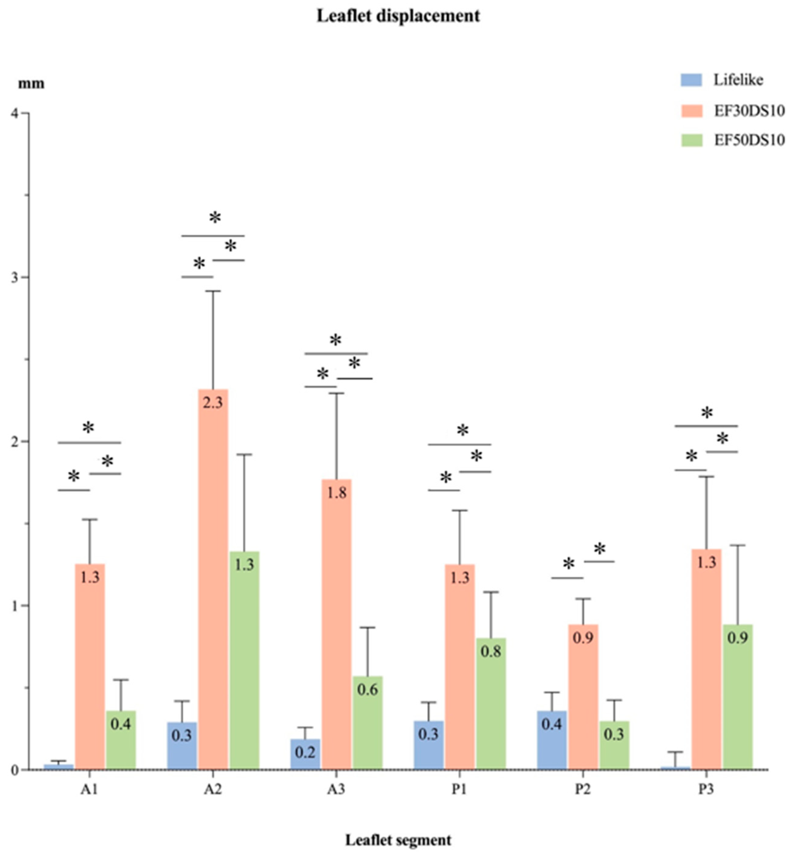
Figure 6.
Major (E1) and minor (E2) principal strain of silicon mitral valves during systolic phase (a) Lifelike E1, (b) V5 E1, (c) V7 E1, (d) Lifelike E2, (e) V5 E2, (f) V7 E2. Strain field on the leaflet surface of the two most physiological silicon mitral valves with comparison to the model hydrogel mitral valve. Major and minor strains were analyzed by using DIC technique during the systolic cardiac phase. (V5 = EF30DS10, V7 = EF50DS10).
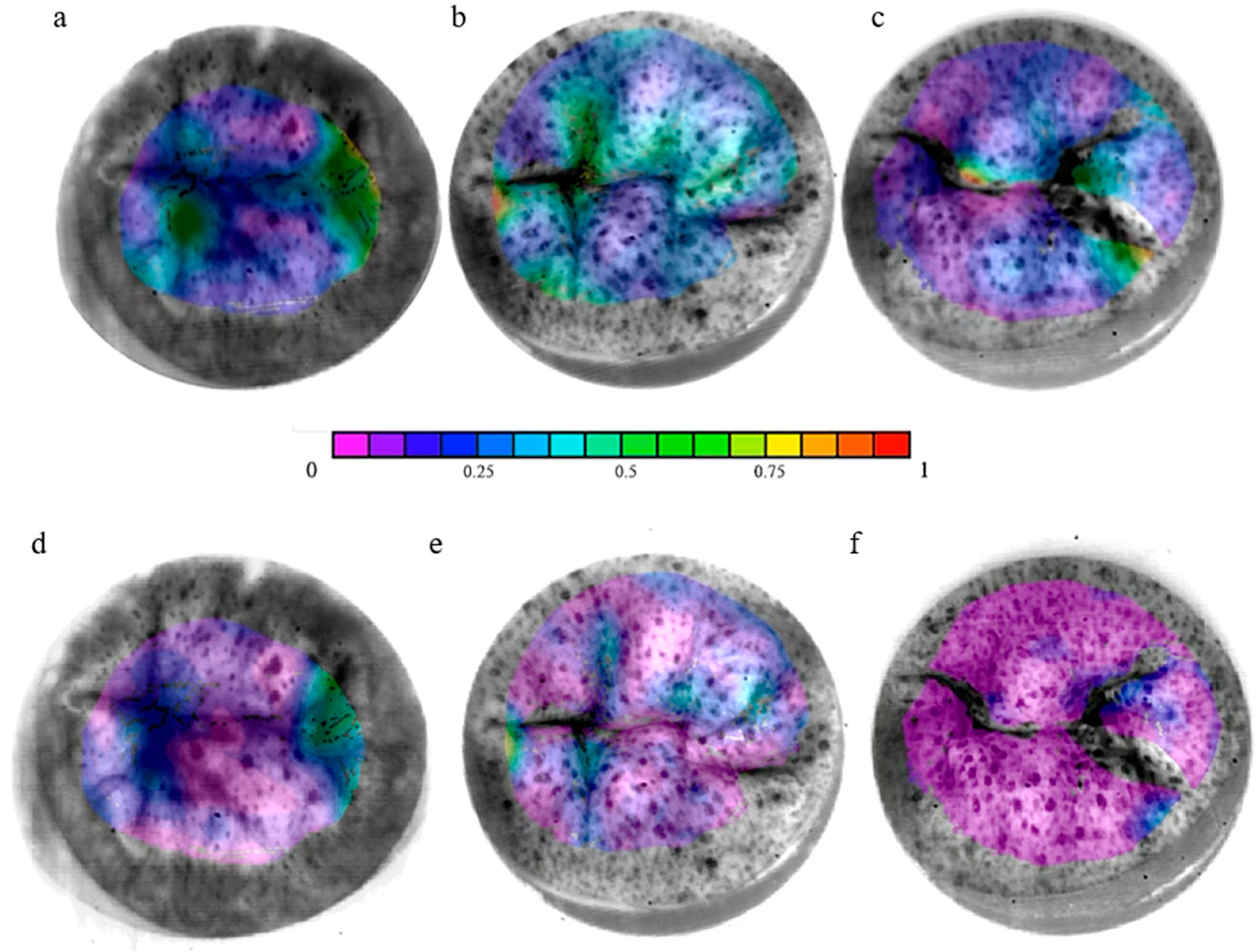
Figure 7.
Major principal strain (E1) of each leaflet segment of silicon mitral valves during systolic phase. Principal major strain (E1) during systolic cardiac phase represented for different regions of mitral valve (A1, A2, A3, P1, P2, P3). (EF30DS10 = V5, EF50DS10 = V7). *: p<0.005, **: p<0.001.
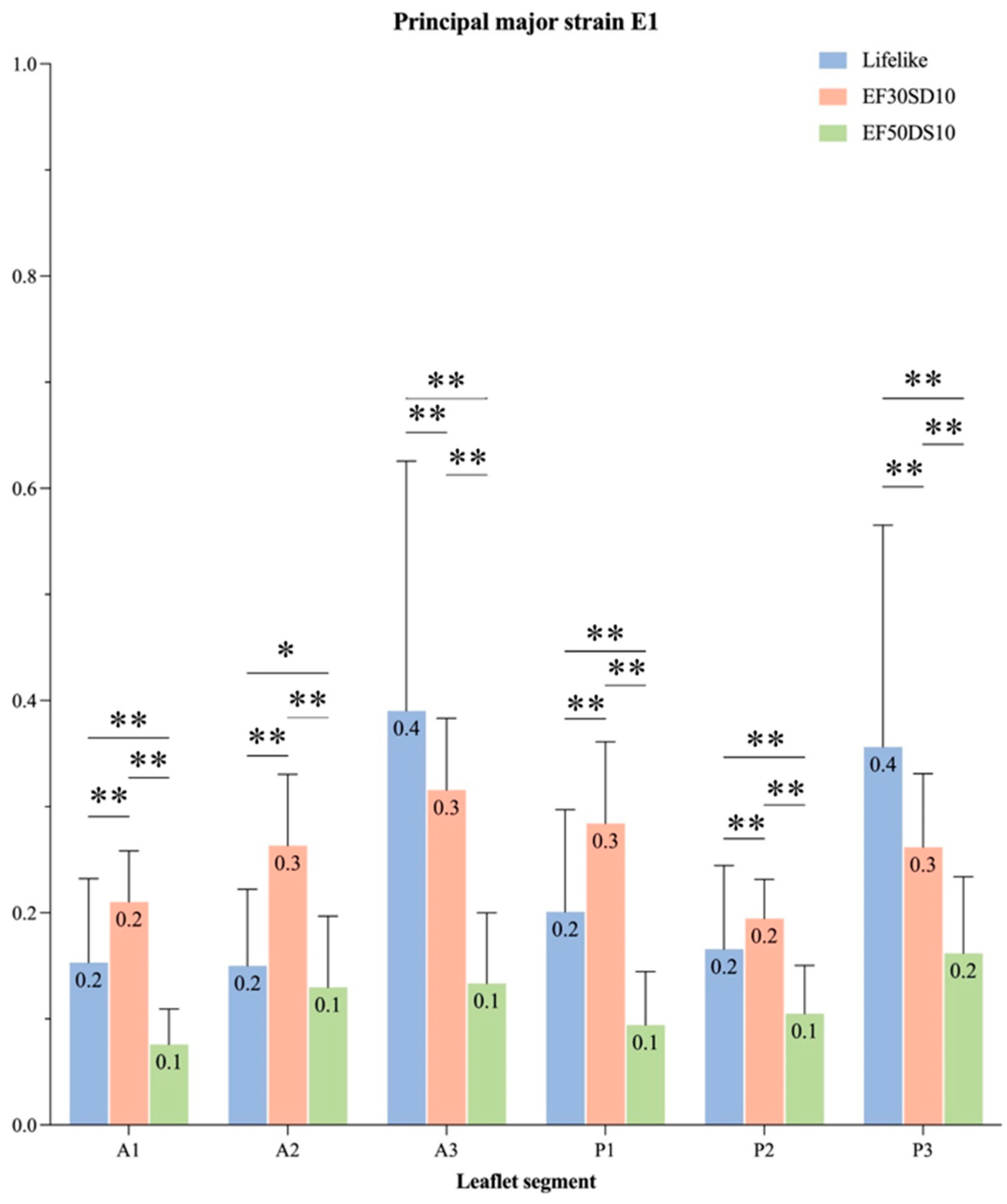
Figure 8.
Minor principal strain (E2) of each leaflet segment of silicon mitral valves during systolic phase. Principal minor strain (E2) during systolic cardiac phase represented for different regions of mitral valve (A1, A2, A3, P1, P2, P3). (EF30DS10 = V5, EF50DS10 = V7). *: p<0.005, **: p<0.001.
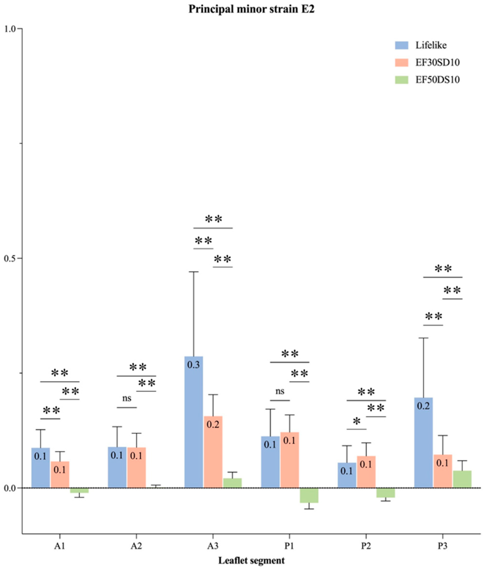

Table 1.
Silicon combinations used for the development of custom-made mitral valves.
| Valve | External Silicon Layers | Internal Silicon Layers |
|---|---|---|
| V1 | EcoFlex 00-30 | |
| V2 | EcoFlex 00-50 | |
| V3 | DragonSkin 10 Very Fast | |
| V4 | DragonSkin 20 | |
| V5 | EcoFlex 00-30 | DragonSkin 10 Very Fast |
| V6 | EcoFlex 00-30 | DragonSkin 20 |
| V7 | EcoFlex 00-50 | DragonSkin 10 Very Fast |
| V8 | EcoFlex 00-50 | DragonSkin 20 |
| V9 | DragonSkin 10 Very Fast | EcoFlex 00-30 |
| V10 | DragonSkin 10 Very Fast | EcoFlex 00-50 |
| V11 | DragonSkin 20 | EcoFlex 00-30 |
| V12 | DragonSkin 20 | EcoFlex 00-50 |
Table 2.
Material properties of tested silicones.
| Material | Young’s Modulus (MPa) | Ultimate Tensile Strength (MPa) | Elongation at Break (%) | Failure Strength (kN/m) | Shore Hardness (00-A) |
|---|---|---|---|---|---|
| EcoFlex 00-30 | 0.33 | 1.2 | 835 | 6.66 | 00-23 |
| EcoFlex 00-50 | 0.33 | 1.7 | 860 | 8.77 | 00-35 |
| DragonSkin 10 Very Fast | 1.04 | 3.28 | 1000 | 17.9 | 10A |
| DragonSkin 20 | 3.84 | 3.79 | 620 | 21 | 20A |
| Native Mitral Leaflet (circ.) | 0.02-10.2 | ______ | ______ | 0.981 | ______ |
| Native Mitral Leaflet (rad.) | 0.02-2.1 | ______ | ______ | 0.657 | ______ |
Table 3.
Hemodynamical parameters induced by the silicon mitral valve.
| Valve | MVA (cm²) | Peak GOA (cm²) | MPG (mmHg) | Vmax (cm/s) | VTI (cm) | DVI | GROA (cm²) |
|---|---|---|---|---|---|---|---|
| Lifelike | 4.0 ± 0.2 | 4.7 ± 0.1 | 2.7 ± 0.4 | 1.5 ± 0.1 | 35.2 ± 2.8 | 1.0 ± 0.1 | 0.00 ± 0.0 |
| V1 | 4.6 ± 0.3 | 4.1 ± 0.1 | 2.0 ± 0.3 | 1.3 ± 0.1 | 29.4 ± 2.6 | 0.8 ± 0.1 | 0.02 ± 0.0 |
| V2 | 3.6 ± 0.3 | 3.2 ± 0.2 | 3.4 ± 0.5 | 1.6 ± 0.1 | 33.7 ± 2.5 | 1.0 ± 0.1 | 0.02 ± 0.0 |
| V3 | 1.8 ± 0.1 | 1.4 ± 0.1 | 12.7 ± 0.8 | 3.2 ± 0.1 | 66.5 ± 3.0 | 1.9 ± 0.1 | 0.03 ± 0.0 |
| V4 | 3.8 ± 0.2 | 3.2 ± 0.1 | 2.9 ± 0.3 | 1.5 ± 0.1 | 30.7 ± 2.3 | 0.9 ± 0.1 | 0.03 ± 0.0 |
| V5 | 4.8 ± 0.1 | 4.0 ± 0.2 | 1.8 ± 0.1 | 1.2 ± 0.0 | 29.3 ± 0.8 | 0.8 ± 0.0 | 0.06 ± 0.0 |
| V6 | 3.3 ± 0.1 | 3.0 ± 0.1 | 4.1 ± 0.4 | 1.9 ± 0.1 | 37.2 ± 2.4 | 1.1 ± 0.1 | 0.00 ± 0.0 |
| V7 | 5.1 ± 0.4 | 5.0 ± 0.2 | 1.7 ± 0.2 | 1.2 ± 0.1 | 28.2 ± 2.1 | 0.8 ± 0.1 | 0.07± 0.0 |
| V8 | 4.2 ± 0.2 | 3.7 ± 0.1 | 2.5 ± 0.2 | 1.4 ± 0.1 | 30.4 ± 1.9 | 0.9 ± 0.1 | 0.06 ± 0.0 |
| V9 | 3.9 ± 0.2 | 4.3 ± 0.3 | 2.8 ± 0.3 | 1.7 ± 0.1 | 37.3 ± 2.1 | 1.1 ± 0.1 | 0.20 ± 0.0 |
| V10 | 2.3 ± 0.1 | 2.9 ± 0.1 | 8.0 ± 0.9 | 2.7 ± 0.1 | 53.1 ± 3.2 | 1.5 ± 0.1 | 0.00 ± 0.0 |
| V11 | 2.5 ± 0.1 | 2.6 ± 0.1 | 7.0 ± 0.5 | 2.5 ± 0.1 | 52.2 ± 2.9 | 1.5 ± 0.1 | 0.00 ± 0.0 |
| V12 | 3.7 ± 0.2 | 3.7 ± 0.1 | 3.2 ± 0.3 | 1.7 ± 0.1 | 32.9 ± 2.0 | 0.9 ± 0.1 | 0.04 ± 0.0 |
MVA: Mitral Valve Area; GOA: Geometric Orifice Area; MPG: Mean Pressure Gradient; VTI: Velocity-Time Integral; DVI: Doppler Velocity Index; GROA: Geometric Regurgitant Orifice Area.
| MPG (mmHg) | MVA (cm²) | GROA (cm²) | |
|---|---|---|---|
| Healthy | ≤ 3 | 4-6 | < 0.20 |
| Mild to moderate | < 5 | > 1.5 | 0.20 - 0.29 |
| Severe | 5-10 | <1.5 | 0.30 – 0.39 |
MVA: Mitral Valve Area; GROA: Geometric Regurgitant Orifice Area; MPG: Mean Pressure Gradient.
Table 5.
Hemodynamical parameters induced by different leaflet thickness of three silicon mitral valve.
Table 5.
Hemodynamical parameters induced by different leaflet thickness of three silicon mitral valve.
| Valve | Leaflet Thickness (mm) | MVA (cm²) | GOA (cm²) | MPG (mmHg) |
|---|---|---|---|---|
| V1 | 1 | N/A | ||
| 1.5 | 4.6 ± 0.3 | 4.1 ± 0.1 | 2.0 ± 0.3 | |
| 2 | 1.8 ± 0.1 | 1.9 ± 0.1 | 7.1 ± 0.8 | |
| V5 | 1 | 3.0 ± 0.2 | 3.8 ± 0.2 | 2.4 ± 0.2 |
| 1.5 | 4.8 ± 0.1 | 4.0 ± 0.2 | 1.8 ± 0.1 | |
| 2 | 2.2 ± 0.1 | 2.6 ± 0.1 | 4.5 ± 0.3 | |
| V7 | 1 | 3.7 ± 0.2 | 3.7 ± 0.2 | 2.4 ± 0.2 |
| 1.5 | 5.1 ± 0.4 | 5.0 ± 0.2 | 1.7 ± 0.2 | |
| 2 | 2.1 ± 0.1 | 2.8 ± 0.2 | 4.6 ± 0.2 | |
MVA: Mitral Valve Area; GOA: Geometric Orifice Area; MPG: Mean Pressure Gradient.
Disclaimer/Publisher’s Note: The statements, opinions and data contained in all publications are solely those of the individual author(s) and contributor(s) and not of MDPI and/or the editor(s). MDPI and/or the editor(s) disclaim responsibility for any injury to people or property resulting from any ideas, methods, instructions or products referred to in the content. |
© 2025 by the authors. Licensee MDPI, Basel, Switzerland. This article is an open access article distributed under the terms and conditions of the Creative Commons Attribution (CC BY) license (http://creativecommons.org/licenses/by/4.0/).
Copyright: This open access article is published under a Creative Commons CC BY 4.0 license, which permit the free download, distribution, and reuse, provided that the author and preprint are cited in any reuse.


