
Submitted:
23 February 2025
Posted:
24 February 2025
You are already at the latest version
Abstract
The study investigate control of the optical force and its modification with variation of the driving field’s strength in the system levels of the chiral medium for left and right circular polarized light. In addition to orbital and magnetic and spin quantum numbers of applied fields, significant vector field arrows of optical force in chiral media are examined using spatial coordinates, detuning , Rabi frequency and decay rates. The parameters of the probe and control fields’ detuning along with their decay rates and phases are provided to determine the optical force in chiral medium both for left and right circularly polarized fields. The optical force is a function of orbital, magnetic and spin quantum numbers. Using phase, detuning, and Rabi frequency of the control fields as variables, the minimum value of optical force measure is 0.003pN for probe detuning and spatial coordinate while the maximum value of optical force for normalized detuning and transverse radial coordinate is measured to be 0.2pN. Potential uses of optical force in fundamental optics, molecular physics, optomechanics, material science, nanoscience, quantum physics, radar, waveguide, antennas and optical tweezers technology are demonstrated by the results.
Keywords:
Optical force
; electromagnetically chiral medium
; Susceptibility
; Energy density
; Orbital quantum number
1. Introduction
Light-matter interaction is the source of optical forces [1]. Chirality is a Greek word ”χεlρ ”(kheir) which means hand that describes an asymmetry in which an object cannot be superposed on its mirror image by either translation, rotation or both [2]. Chirality is a geometrical characteristic of objects that is present in both macrostructures like human hands and microstructures like molecules [3]. This microscopic optical force is used in the studies of fundamental science such as atomic physics [4], biology [5,6], biochemistry [6,7], optical tweezers [8], materials engineering and nanofabrication [9], clinical medicine [1], photonic force microscopy [10] and to engineering applications optomechanics including quantum information processing [11], high precision sensing and measurement [12], radar [13], waveguide [14] and antennas [15]. On the basis of these wide range of applications, optical force has been studied by numerous researchers both theoretically and experimentally. In chiral media, the incidence of electromagnetic wave and its propagation were investigated by Bassiri et al [16]. Wang and Chan demonstrated that a chiral particle close to a substrate can experience a lateral optical force due to an electromagnetic plane wave [17]. According to the prediction of Hayat’s et al. [2], chiral particles experience lateral optical forces as a result of the evanescent waves’ transverse spin angular momentum (SAM) density using interference fields in order to study lateral optical forces by creating them on chiral particles. As stated by Zhang et al [18], chiral cholesteric beads of micron size confined in either stable or unstable trap potentials suffer a chiral optical force. Kucirka and Shekhtman’s [19] theoretical suggestion is the first demonstration of the feasibility of inducing a force through the coupling of matter’s chirality and light’s helicity. Zhao et al. [20] proposed a theory of effective media model in order to show several types of chiral structures in an effective medium. A significant optical chiral response with 700 nm wavelength has been achieved by Mark et al. [21] in two-pitched gold nanohelices. Using this technique Bai et al. [22] created silver nanohelices exhibiting optical chiral responses at a reduced wavelength. Chiral nanostructures have also been produced by Cathcart and Kitaev [23] using a self-assembly method. In the presence of chiral molecules, Lee et al. [24] produced gold nanoparticles and the chirality of the molecules was transferred to the nanoparticles. Zhu and colleagues [25] conducted theoretical and experimental investigations of a two-dimensional spiral structure on a metal film and subsequently compared the results with those of 3D helical and 2D extrinsic chiral structures. Decker et al. [26] noticed a minor optical chiral reaction by gently disrupting the symmetry in two layers of varying diameters. Plum et al. [27] introduced a slightly rotating misalignment which resulted in a comparatively stronger optical chirality. Significant optical chirality has been obtained by Menzel et al.[28] through the effective implementation of connection between bar and L-shaped nanostructures. Using multistep lithography, Zhao et al. [20] created a multilayer device and noted a significant broad band optical chiral response as the number of layers rose. Chiral molecules were detected by Gao et al. [29] and Li et al. [30] by altering the CD spectrum of chiral nanostructures in living cells. Currently, nanospirals showing strong optical chiral response and remarkable qualities were fabricated by Esposito et al. [31] in the visible regime by using multiple localized surface Plasmon resonances (LSPRs). A strong optical chirality structures have also been created by Karimullah et al.[32].
Optical force, including the force in chiral media, has been actively investigated as shown above and consequently a lot of work is available in the literature. However, to the best of our knowledge no research on the manipulation and control of optical force in chiral media by coherent driving fields has been published. In order to regulate and adjust the optical field in a chiral medium we present in this study a four-level atomic system driven by a probe and control fields. The optical force in chiral media can be significantly enhanced by varying the characteristics and strength of the control and probe fields.
2. Model and Equations
The proposed atomic system consists of a four levels driven by a probe field and two control fields as depicted in FIG1. The probe field Ep having Rabi frequency Ωp and detuning ∆p is coupled with the levels |2> and |4>. The control field Em, which is coupled to levels |1> and |3> has a Rabi frequency Ωm and detuning∆m.The levels |3> and |4> are coupled with another control field Ec of Rabi frequency Ωc and detuning ∆c. We denote the decay rates from state m to state n as γmn whereas the detunings are given by ∆p = ωp - ω24, ∆m = ωm - ω13, and ∆c = ωc - ω34. The non-interacting Hamiltonian H0 of the four level system is of the form;
,, and represent the atoms frequency of the sodium medium respectively. The interaction picture Hamiltonian Hint of the host four level atomic system is represented as;
Here, are the detuning of the system respectively. The complex Rabi frequencies Ωc, Ωm, and Ωp are written as Ωi=c,m,p = exp[iϕc]. The general master equation of density matrix is given by;
In the above equation, D is the system’s general density operator, Hint indicates the system’s interaction Hamiltonian, represent the spontaneous decay rates such as γ43, γ42, and γ31, implying the decay from the excited state |4> to the ground states j ( j= 1,2,3) respectively and δ and δ+ are the general lowering and raising operators associated with all of the transitions between the energy states |1> and |4> in our proposed four level atomic system as shown in Figure 1.
The parity of levels |1>, |2>, and |3> is the same as that of level |4>, but it is opposite. Transition from level |4> to levels |2> and |3> are permissible for electrical dipoles, whereas level |3> to level |1> is prohibited for electrical dipoles but permissible for magnetic dipoles. We consider that the states |1> and |2> are stable. The electric and magnetic components of a left and right circular polarization probe field, ωp and ωm, respectively, further link the states |2> and |4> with their electric dipole moment of σ42 and the states |1> and |3> with their magnetic dipole moment of µ31. We obtain sixteen density matrix equations by evaluating the master density matrix equation (3) after long algebraic calculation. The coupled rate equations of the four level system obtained from the sixteen density matrix equations under the condition, ∆p = ∆m = ∆, are given by;
where the terms A (1−4) in equations (4), (5), (6), and (7) are;
The dipole moments matrix elements for electromagnetically chiral medium are represented in the form as;
where, λ = 2πc/ω is the wavelength of light in free space. Here, ω is the angular frequency while c is the beam’s speed. We suggest that the probe field intensity is significantly lower than other laser fields present, i.e., Ωp, Ωm ≪ Ωc, γ43, γ42 and that the ground state | 1> is being populated by all the atoms, i.e., 11 =1 and 22=33 =44 = 0. Thus, it is sufficient to retain in equations (4) to (7) simply the linear terms of the Rabi frequencies Ωp and Ωm. In relation to the probing field’s Rabi frequencies, the matrix elements D11, D22, D12, and D21 are invariably needed to be the zero order. The steady state equations for the matrix element can be obtained from equations (4) to (7) by applying these approximations and they are as follows;
Chiral media refers to a medium composed of chiral molecules or particles. One amazing characteristic of such medium is the rotation of the polarization of electromagnetic waves that are passing through it. This rotation phenomenon is also known as optical activity [33]. Enantiomers, often known as left or right handed molecules, are chiral objects and their mirror images. Both types of objects are referred to as enantiomorphs. Since chirality is produced by symmetry breaking, so it is significant to fundamental physics [17]. The primary feature of chiral media is the cross coupling between the magnetic and electric fields during an electromagnetic wave propagation through the material. This phenomenon is explained by a dimensionless chirality parameter (χ). Chiral media reacts differently to left circularly polarized (LCP) and right circularly polarized (RCP) light due to its symmetry [16,34]. Since light lacks geometry so it cannot be chiral in the traditional sense; however, there are characteristics that can be used to characterize light’s chirality. Additionally, orbital angular momentum which forms a helical shape on the wave front can be carried by light. Chromatic light is defined by its chiroptical properties which include orbital and spin angular momenta (Lz and Sz), optical helicity fluxes (Φχ and Φh), and spin density fluxes (Le and Lm). Chiral light can be defined with these characteristics. Analogously, the chirality of an entity can be measured using the chiral polarizability tensor (αc) and chirality parameter (χ). In order to address this problem, Pendry [35] has developed a sophisticated solution in relation with a medium in which the magnetization M of an incident optical frequency electromagnetic waves is coupled to the electric field component E and the electric polarization P is coupled to the free space magnetic field component as given below;
where, ζEH and ζHE are the complex chirality coefficients and χe and χm are the electric and magnetic susceptibilities. The refractive indices of electromagnetic chirality media for left and right circular polarization probe fields are given by, respectively.
P = χeE + ζEH H
M = χmH + ζHEE
Originally the atom is prepared in the coherent superposition state, where Consequently, in equations (13) and (14), the matrix elements at the zero order approximation become, where is the angle of polarization. Using the formulas one may obtain the ensemble electric polarization P and magnetization M of the chiral medium at the probe field frequency as, P = Nσ24D42 and M = Nµ13D31 respectively. Here throughout the paper the bold face letters represent vector quantities whereas N is the density or number of atoms of the sodium medium. Substituting equations (13) and (14) into the formulae for the ensemble electric polarization and magnetization, we obtain the relations as follows;
where
P = αEBB + αEEE
and M = αBBB + αBEE
In equations (23) and (24), B is substituted by H in accordance with the relation, B = (H + M).
After calculation, we get the following result;
The chiral medium’s dielectric function is expressed as;
The electric susceptibility χe of the probe field for chiral medium is calculated from the term 24 as;
By substituting equation (28) in equation (27), we obtain that;
The relative permeability of the chiral medium is determined with the help of magnetic susceptibility as;
where,
After substituting equation (31) in equation (30), we get;
Here, the complex chirality coefficients can be expressed with the choice of as;
where ko = 2π/λ, is the wave number of light in free space. In the host electromagnetic chiral medium, the wave number for left and right circular polarized light are given respectively as;
where k0 = ω/c, is the wave number of light in free space. Using a spatial light modulator which has the ability to transform the spatial and phase distributions of optical fields and so develop an optical vortex beam is an effective technique of generating laser beams that carry orbital angular momentum (OAM) [36]. Considering a vortex Laguerre Gaussian (LG) beam that is azimuthally E-polarized with total electric field [37] is expressed as;
kL = k0nrL
kR = k0nrR
Here, is the amplitude of an azimuthally E-polarized vortex Laguerre Gaussian (LG) beam. The caret () represents unit vectors while unit vectors along the spatial coordinates x, y and z are defined by and respectively. Here, ρ, ϕ, and z are the cylindrical coordinates of the Laguerre Gaussian beam (LG) whereas the unit vectors of the first two coordinates are;
If we consider Maxwell’s third equation,, the magnetic field B [38] in cylindrical coordinates is determined as;
Here, the Laplacian of the Laguerre Gaussian beam is of the form;
By substituting equations (37) and Laplacian from equation (41) in to equation (40), we get the equation as;
The expression for the amplitude of an azimuthally E-polarized vortex beam with total electric field [39] is given by;
The longitudinal magnetic field Bz is calculated from equation (42) by using the values of amplitude of an azimuthally E-polarized vortex beam from equation (43) and this calculation yields;
where, is the Laguerre Gaussian (LG) beam’s width, is the Gaussian’s beam waist, is the probability density, is the Gouy phase, is the Rayleigh diffraction length or Rayleigh range of beam, and is the radius of curvature of Laguerre Gaussian (LG) beam’s wave fronts, whereas is the associated Laguerre polynomial which is expressed as;
Here, in equation (46) s is the spin angular momentum number or s-number, l is orbital angular momentum or l-number, m is magnetic quantum number or m-number, and ρ is the probability density. The orbital quantum number l commonly referred to as the “topological charge” is a property of light fields. It can have integer or half-integer values. In the case of an electromagnetic chiral medium, the optical force [40] for left and right circularly polarized vector fields is expressed by the following equations;
Equations (47) and (48) are the optical forces for left and right circular polarized light respectively, which originate from light-matter interaction. Here, αL and αR are the polarizibilities, W is the energy density, and PL and PR are the linear momentum for left and right circular polarized light respectively, whereas g is the g-factor. In atomic units, g-factor is g=1 and in Gaussian units, g = (8πω)−1. The angular and linear photon momentum of a light beam has been predicted by Maxwell’s equations41. Laguerre Gaussian (LG) beams that are circularly polarized can carry both spin angular momentum (SAM) and orbital angular momentum (OAM). Spin angular momentum (SAM) is transferred from light to internal electronic degrees of freedom when it impinges upon a chiral material through the interaction between the light and the substance. The interaction of light with material particles can cause a torque (force) when the incident light has orbital angular momentum (OAM) which can cause the particle to rotate along the beam’s axis [41]. The multiple interaction between the incident light field and the material’s electromagnetic modes explains the orbital angular momentum (OAM) transfer phenomenon [37,42,43]. The transfer of spin angular momentum (SAM) causes the particles to spin about their own axes and is dependent on the polarization of the beam. The OAM appears in Laguerre-Gaussian (LG) beams with helical phase distributions and its transfer causes the particles to orbit the incident beam’s optical axis. The polarizibilities αL and αR in the electromagnetically chiral medium for left and right polarized light are written as;
The energy density of LG beam 40 can be expressed in the form;
Light carries momentum as well as energy. The linear momentum and energy density are directly related to optical force in the chiral medium. The linear momenta [40] carried by the Laguerre Gaussian (LG) beam in electromagnetically chiral medium for left and right circular polarized vector fields are ;
As a matter of fact, PL and PR respectively indicate the liner momentum or radial mode number of the polarized light.
3. Results and Discussion
The results are presented for the vector field arrows of optical force in electromagnetically chiral medium. The plots represents the interaction behavior of the electromagnetic light fields with electromagnetically chiral medium which are denoted by the visual depiction and spatial distribution pattern of vector field arrows in 3D space. This study examines the interaction between left circular polarized (LCP) and right circular polarized (RCP) probe with an electromagnetically chiral medium, which produces optical forces in the form of vector field arrows that distributes in 3D space. The decay rate is considered as γ=1GHz and other frequencies parameters are scales to this decay rate γ. Further, ω = 1000γ, λ = 2πc/ω, ko = ω/c,, whereas = (1, 0, 0)x/λ, = (0, 1, 0)y/λ, and = (0, 0, 1)z/λ. Atomic units are used throughout the paper. The main parameters involved in this study include the orbital quantum number, also known as the topological charge (l), which defines the variation of optical field which is directly linked to the orbital angular momentum (OAM) of light. The OAM is expressed as L = lℏ, where ℏ represents the reduced Planck constant. The topological charge l is a key concept in both optics and physics that describes the characteristics of optical vortices. This charge is essential for determining various properties of optical vortices, including orbital angular momentum (OAM), the distribution of optical forces, and the stability and dynamics of vortices. Additionally, the sign of the topological charge (l) indicates the handedness of the helical structure: a positive (l) value results in a clockwise helical structure, while a negative (l) value produces a counter clockwise helical structure. The magnetic quantum number (m) defines how the orbital angular momentum (OAM) is projected along the direction of propagation. Specifically, when m=0, it means there is no magnetic moment linked to the optical vortex, leading to a balanced optical force distribution in the chiral medium. In contrast, when m=1, a non-zero magnetic moment is present, which causes an uneven optical force distribution. The spin quantum number (s) pertains to the intrinsic angular momentum and polarization of the photon. Collectively, these quantum numbers (l, m, s) play a crucial role in dictating how the optical force is distributed within the medium. As electromagnetic light interacts with the chiral medium, its chirality prompts a momentum transfer, creating an optical force F represented by left circular polarized (LCP) and right circular polarized (RCP) fields, aligned with the light field. The direction and magnitude of the force F are influenced by the values and signs of the quantum numbers l, m, and s. In a chiral medium, this optical force is depicted by vector field arrows that vary in orientation and intensity, illustrating the force's direction and magnitude at different points in 3D space. In our study, we use the topological charge (l), magnetic quantum number (m) and spin quantum number (s), to describe the optical vortices created by the interaction between electromagnetic light and the chiral medium. The orbital quantum number (topological charge) (l) ranges from ±2 to ±4, magntic quantum number from 0 to 1 while the spin quantum number remains constant at (s=1). The phase of the vector field arrows, which shows the orientation of the left circularly polarized (LCP) and right circularly polarized (RCP) distribution of the optical force at each point, is affected by both the topological charge (l) and the spin quantum number (s). The polarization of the probe fields, being either LCP or RCP, determines the handedness of the helical force distribution. Specifically, LCP probe fields create a counterclockwise helical force distribution, while RCP probe fields produce a clockwise helical force distribution. Therefore, the helicity of the light field (whether clockwise or counterclockwise) is dictated by the topological charge (l) and the spin quantum number (s). Additionally, the symmetry of the vector field arrows is shaped by the values of orbital quantum number (topological charge) l and magnetic quantum number (m), reflecting the fundamental physics of the interaction between light and the chiral medium. The distribution of the optical force (F) can be utilized to trap and manipulate particles. In this paper the blue vector distribution arrows represent left circular polarization field (LCP) whereas red vector distribution arrows are for right circular polarization field (RCP) lines.
In FIG 2(a-h), the plots are traced for the vector field arrows of optical force in electromagnetically chiral medium for left and right circular polarization probe fields versus spatial coordinates’ x/λ, y/λ, and z/λ in 3D space. The left and right circular polarization vector field arrows of optical force are strong variation function of the spatial coordinates’ x/λ, y/λ, and z/λ for orbital quantum number l, magnetic quantum number m as well as spin quantum number s. Also each left and right circular polarization vector field arrow represents magnitude and direction of the optical force in electromagnetically chiral medium. The distribution of optical forces is examined for left circularly polarized (LCP) fields (Figures 2(a-d), represented by blue arrows and right circularly polarized (RCP) fields (Figures 2(e-h), represented by red arrows along the normalized spatial coordinates x/λ, y/λ, and z/λ in a three-dimensional space. FIGs 2(a-d); represent left circularly polarized (LCP) field analysis and explanation of each plot for (l = ±2, ±4 m = 0, 1, s = 1). In FIG 2(a), the optical force distribution reveals a well-defined vortex-like field characterized by a chiral pattern due to the orbital quantum number, l = +2. The force vectors exhibit a counter clockwise rotation, indicating a positive helicity contribution from the LCP field and moderate optical force for manipulation of particles. The interaction between the optical field and the chiral medium results in localized force intensity, which affects particle trapping or manipulation. FIG 2(b) show that in contrast to FIG 2(a), the vortex structure is inverted due to the negative orbital quantum number l = -2 and negative OAM, resulting in an opposite rotational direction. The optical force vectors now display a clockwise distribution pattern, confirming the OAM-dependent optical force behavior in the chiral medium. The overall field intensity remains similar to FIG 2(a), but the directionality is reversed. FIG 2(c) shows that Increasing the orbital quantum number to l = +4 enhances the chiral nature of the force field, creating a more tightly vortex similar to FIG 2(a). The force vectors continue to rotate counter clockwise but with greater spatial complexity, leading to a stronger optical torque (force) effect. FIG 2(d) indicates the inversion of OAM at l = -4 results in a more pronounced clockwise vortex compared to FIG 2(b). The increase in the orbital quantum number (l), which corresponds to topological charge and OAM magnitude, intensifies the optical force distribution, showcasing significant variations in vector density and strength (magnitude) of optical force for particle trapping and manipulation. The explanation and analysis of each plot of the right circularly polarized (RCP) field for (l = ±2, ±4 m = 0, 1, s = 1), as shown in FIGs 2(e-h). FIG 2(e); In the case of right circular polarized (RCP) vector field arrows, unlike the left circular polarized (LCP) field vector arrows, a clockwise vortex is induced for the same orbital angular momentum (OAM) value (l = +2). The optical force vectors appear mirrored when compared to FIG 2(a), reflecting the fundamental handedness of the polarization shown in FIG 2(e). In FIG 2(f) with (l = -2), the optical force field structure is counter clockwise, which is the opposite of FIG 2(b). This observation confirms that RCP fields produce an opposite torque (force) effect compared to LCP fields in a chiral medium. At (l = +4), the optical force vectors exhibit a more pronounced clockwise vortex, contrasting with FIG 2(c), and show stronger spatial confinement. This indicates that higher OAM enhances the chiral-dependent optical force, while the handedness remains reversed compared to the LCP field, as illustrated in FIG 2(g). In FIG 2(h) for (l = -4), a counter clockwise vortex is observed, which is opposite to FIG 2(d). The increased magnitude of OAM results in more significant optical force effects, aligning with previous findings. The comparative analysis of LCP in FIGs 2(a-d) versus RCP in FIGs 2(e-h) reveals opposite rotation patterns of the optical force vector field arrows. LCP fields generate counter clockwise vortices for positive orbital quantum number and OAM and clockwise for negative orbital quantum number and OAM, while RCP fields display the opposite behavior. Additionally, comparing the figures shows that both LCP and RCP fields of optical force are dependent on orbital quantum number and corresponding OAM. Higher orbital quantum number values (l = ±4) lead to stronger optical forces and tighter vortex formations and OAM in both cases. The results confirm that the optical force in a chiral medium is influenced by both the handedness of polarization and OAM, resulting in opposite vector distributions for LCP and RCP fields with the same orbital quantum number values, highlighting the impact of the chiral medium. This study illustrates that chiral media significantly affect optical force distributions based on the handedness of circular polarization and orbital quantum numbers. These effects can be utilized for optical tapping and manipulation of microscopic particles, atoms, molecules and nanoparticles, torque applications and chiral-dependent optical manipulations in sophisticated photonic systems.
In Figure 3(a-h), the plots are traced for the vector field arrows of optical force in an electromagnetically chiral medium for left circular polarized (LCP) field and right circular polarized (RCP) field versus detunings of probe and control fields ∆c/γ, ∆m/γ, and ∆p/γ at the orbital, magnetic as well as spin quantum numbers in 3D space. The magnitude and direction of the optical force are represented by each vector arrow of left and right circular polarized vector field at that point with variation of probe detuning and control fields’ ∆c/γ, ∆m/γ, and ∆p/γ. This study explores how electromagnetic light interacts with an electromagnetically chiral medium, resulting in optical forces depicted as vector field arrows. The distributions of optical forces are analyzed based on the normalized detuning parameters ∆c/γ, ∆m/γ, and ∆p/γ, which affect the medium's optical response. A crucial part of this analysis show dependence of optical forces on the orbital quantum numbers l = ±2, ±4, influencing both the direction and intensity of the optical forces. FIGs 3(a-d); highlights each plot analysis and explanation of left circularly polarized (LCP) field for (l = ±2, ±4, m = 0, 1, s = 1). FIG 3(a); for (l = +2), shows that the optical force field has a counter clockwise vortex-like structure due to the positive orbital quantum number and its corresponding OAM. The force vectors exhibit stronger magnitudes in certain regions of ∆c/γ and ∆p/γ, where the interaction between the optical field and the chiral medium is resonant. This indicates the existence of stable trapping regions where optical forces can confine particles within specific areas. In FIG 3(b) at (l = -2), the optical force distribution pattern mirrors that of FIG 3(a), displaying a clockwise rotation, which reflects the reversal of vortex direction due to the negative quantum number and its corresponding topological charge and OAM. While the force magnitude remains similar, the direction of the optical force changes, illustrating that the sign of the orbital quantum number l influences the chirality of the optical force field. This reversal indicates that chiral optical forces can be adjusted using orbital quantum number and OAM to control the movement of microscopic particles within the medium. For (l = +4) in FIG 3(c); it is observed that increasing the orbital quantum number to l = +4 results in a more tightly twisting counter lock wise vortex, with a higher vector density. The magnitude of the optical force is greater than that shown in FIG 3(a), indicating a more robust interaction between the optical field and the chiral medium. The optical force vectors create a more complex pattern, suggesting enhanced optical force effects and stronger confinement areas. These vectors display a pronounced clockwise vortex, contrasting with FIG 3(c), due to the negative orbital quantum number and related OAM (l = -4) as illustrated in FIG 3(d) at (l = -4). The increase in orbital quantum number and OAM magnitude leads to more localized forces, indicating that the enhancement of optical force scales with higher values of topological charge (l). This supports the idea that both OAM and circular polarization affect the distribution of optical forces in a chiral medium. FIGs 3(e-h) provide analysis of the right circularly polarized (RCP) field for l=±2, ±4, m=0, 1 and s=1, in a chiral medium. In FIG 3(e); at (l = +2), the results contrast with those in FIG 3(a), where the optical force distribution shows a clockwise vortex, indicating a reversal in optical force direction due to the right circularly polarized (RCP) nature of the probe field. The magnitude and spatial structure of the optical force are similar to those in FIG 3(a), but the handedness of the force field is inverted. The optical force vectors exhibit a counter clockwise rotation, opposite to FIG 3(b), as shown in FIG 3(f) at (l = -2). This confirms the anticipated polarization-dependent inversion of optical force directions, where RCP and LCP fields produce opposite orientations of force vectors for the same orbital quantum number and OAM. In FIG 3(g) with (l = +4), a strongly twisting clockwise vortex is observed, contrasting with the LCP counterpart in FIG 3(c). The optical force vectors show increased confinement and intensity, confirming that higher orbital quantum number and OAM enhances the greatly magnitude of optical forces, regardless of polarization. FIG 3(h) at (l = -4) illustrates that the optical force vectors create a counter clockwise vortex, contrasting with FIG 3(d). The heightened orbital quantum number magnitude leads to stronger localization of optical forces, emphasizing the role of OAM in chiral force distributions. The comparative analysis reveals opposing rotational patterns or structures of LCP in FIGs 3(a-d) compared to RCP in FIGs 3(e-h). LCP fields generate counter clockwise vortices for l > 0 and clockwise vortices for l < 0, while RCP fields exhibit the opposite behavior, producing clockwise vortices for l > 0 and counter clockwise vortices for l < 0. This underscores the fundamental influence of polarization handedness on the distribution of optical forces. The analysis also indicates a dependence on OAM, where increasing orbital quantum number (l = ±4) amplifies the optical force magnitude, resulting in more compact and intense vortex structures. As the orbital quantum number or topological charge (l) increases, the optical force becomes more localized, allowing for enhanced precision in optical manipulation. The influence of the chiral medium modifies optical forces based on both the sign of orbital quantum number and the handedness of circular polarization. The distribution patterns of optical forces between LCP and RCP fields are mirrored, highlighting the chiral-dependent nature of these interactions. This study confirms that the distributions of optical forces in chiral media are influenced by polarization handedness and the sign of orbital quantum number l. The contrasting force orientations between LCP and RCP fields emphasize the polarization-induced inversion of optical forces. Furthermore, increasing the orbital quantum number l (topological charge) and OAM strengthens and localizes optical forces, making them more effective for applications like optical trapping, chiral separation, and torque-driven manipulation in photonics nanotechnology.
In the plots of Figure 4(a-h), vector fields of optical force for left circular polarized (LCP) field and right circular polarized (RCP) field in an electromagnetically chiral medium versus decay rates γ32/γ, γ42/γ, and spatial coordinate z/λ are traced in 3D space. The vector field arrows of optical force for LCP and RCP fields are small variation function of decay rates of control fields γ32/γ, γ42/γ, and spatial coordinate z/λ at the orbital, magnetic as well as spin quantum numbers. Each arrow of LCP and RCP fields represent magnitude and direction of optical force with variation of decay rates of control fields γ32/γ, γ42/γ, and spatial coordinate z/λ in chiral medium. This study examines how an electromagnetic field interacts with an electromagnetically chiral medium, resulting in the creation of optical forces depicted by vector field arrows. The analysis focuses on these optical forces for both LCP (FIGs 4(a-d), indicated by blue arrows and RCP (FIGs 4(e-h), indicated by red arrows probe fields, considering various parameters. Unlike earlier studies, the optical forces here are assessed as functions of the parameters γ32, γ42, and z/λ, which are associated with decay rates and the spatial distribution of the force vectors. The impact of orbital quantum numbers, l = ±2, ±4 is also explored, revealing insights into the rotational behavior and intensity of optical forces within the chiral medium. Each FIG corresponds to different orbital angular momentum (l) values while maintaining fixed spin (s = 1) and magnetic quantum number (m = 0, 1). Here, FIGs 4(a-d) for l=±2, ±4, m=0, 1 and s=1, provide the left circular polarized field (LCP) analysis and explanation in chiral medium. In FIG 4(a) where l = +2; the optical force vectors appear uniform in a single direction with no significant difference between the left-handed and right-handed vectors, showing no rotational asymmetry. Similarly, in FIG 4(b) at l = −2, the optical force vectors are also directed uniformly, indicating a symmetric optical force distribution devoid of handedness. This pattern continues for l = +4, as seen in FIG 4(c), where the optical force vectors again point uniformly without displaying chiral characteristics. In FIG 4(d) for l = −4, the optical forces remain consistent, showing a single-direction uniform field and an absence of observable asymmetry between left- and right-handed forces. Consequently, all LCP optical forces exhibit the same vector field distribution in one direction, indicating that under these conditions, LCP does not produce optical chirality effects in this medium and almost same strength or magnitude of optical force for particles trapping and manipulation in one direction in 3D space. FIGs 4(e-h); explore the analysis and explanation of right circular polarized field in chiral medium. In FIG 4(e) at l = +2; the optical force vectors clearly display left and right-handed asymmetry. The direction and strength of the optical force varies across the field instead of being uniform. For l = −2; the optical force distribution remains asymmetric but shows opposite handedness compared to FIG 4(e), as shown in FIG 4(f). The change in handedness is due to the negative value of orbital quantum number l. In FIG 4(g) with l = +4, the handedness pattern continues but exhibits a stronger force distribution and hence greater optical force magnitude for particle manipulation. The chiral asymmetry becomes more evident with the higher orbital quantum number and OAM value. FIG 4(h) displays an asymmetric optical force distribution and strength similar to FIG 4(f), but in the opposite handed configuration corresponding to l = −4. Once again, changing the value of orbital quantum number results in a swap of handedness. In contrast to LCP, RCP optical force distributions reveal marked left- and right-handedness. The optical force arrows do not follow a single uniform direction and strength. Higher orbital quantum number values (l = 4) amplify the asymmetry compared to lower values (l = 2) and greater strength of optical forces. The handedness reverses when transitioning from positive to negative l-values. The comparative analysis of FIG 4(a-d) and FIG 4(e-h) for LCP and RCP indicates that the chiral medium interacts differently with LCP and RCP due to its inherent chiral properties. LCP fields do not trigger a significant chiral interaction, leading to a force that remains uniform. The LCP plots (FIGs 4(a-d)) do not exhibit left or right handedness. This is because the LCP probe fields are sensitive to the orbital quantum number and angular momentum (OAM) of the optical vortex but not to its helicity. Consequently, the LCP plots demonstrate a symmetric distribution of optical force arrows. The RCP plots, shown in FIG 4(e-h), illustrate both left and right handedness. This variation occurs because the RCP probe fields are responsive to both the orbital quantum number and angular momentum (OAM) and the helicity of the optical vortex. The RCP plots display an uneven distribution of optical force arrows, which suggests the presence of helical structures. The orbital quantum number l and OAM plays a role in shaping the spatial structure of optical forces. In the case of RCP, the interplay between spin and orbital quantum number results in optical forces that are asymmetric with respect to handedness. Conversely, under these conditions, LCP does not generate handedness effects due to spin-orbit interaction. The chiral medium reacts differently to left and right circular polarization. For LCP, the interaction maintains symmetry, resulting in unidirectional forces. However, for RCP, a chiral asymmetry arises, causing forces that differentiate between left- and right-handed directions.
In Figure 5(a), the plots are traced for the magnitude of optical force in an electromagnetically chiral medium for left circular polarized vector field for probe detuning ∆p/γ and spatial coordinate z/λ in 2D space. Also the magnitude of left circular polarized vector field of optical force is a function of Rabi frequency of control field |Ωc|. Each plot illustrates the magnitude of optical forces as a function of normalized detuning (Δp/λ) and spatial coordinate (z/λ) for various levels of control field strength ∣Ωc∣. The control field plays a crucial role in determining the magnitude and behavior of the optical force within the chiral medium. This particular plot demonstrates how the magnitude of the optical force varies for a left circularly polarized (LCP) field in relation to Δp/λ and z/λ. Here, the curves correspond to different control field strengths ∣Ωc∣; specifically, for the orange peak, ∣Ωc∣=3γ; for the yellow peak, ∣Ωc∣=4γ; and for the green peak, ∣Ωc∣=5γ, respectively. In other words, the control field strengths |Ωc| varies from 3γ to 5γ for left circular polarized vector field of optical force. The optical force shows peaks and dips, illustrating the resonant interactions between the left-handed circularly polarized (LCP) field and the chiral medium. As the magnitude of ∣Ωc∣ grows from 3γ to 5γ, the magnitude of the optical force also increases, suggesting that stronger control fields result in more powerful optical forces. Additionally, the peak optical force slightly shifts along probe detuning Δp/λ, indicating that the resonance condition adjusts a bit with the increase in ∣Ωc∣. The changes along the spatial coordinate z/λ reveal an oscillatory trend, pointing to periodic modulation of the force in the direction of propagation. The magnitude of optical force in an electromagnetically chiral medium for left circular polarized field for probe detuning ∆p/γ and spatial coordinate z/λ varies from 0pN to 0.04pN as shown in FIG 5(a). In FIG 5(b), the plot also shows the same optical force distribution but for right circular polarized vector field in an electromagnetically chiral medium along the parameters ∆p/γ and z/λ in 2D space. Also the magnitude of right circular polarized vector field of optical force is a function of Rabi frequency of control field |Ωc|. In this case, the strength of control field |Ωc| also varies from 3γ to 5γ but the color scheme is reversed for right circular polarized vector field of optical force compared to FIG. 5(a). The strength of control field for Green peak is; ∣Ωc∣=3γ, for yellow peak is; ∣Ωc∣=4γ and for Orange peak is; ∣Ωc∣=5γ respectively. Similar to FIG. 5(a), the optical force shows resonant peaks and dips that depend on the detuning Δp/λ and the propagation spatial coordinate z/λ. As the magnitude of ∣Ωc∣ increases from 3γ to 5γ, the magnitude of the optical force interactions also rises, indicating that more intense control fields enhance these interactions. The oscillatory pattern of the force distribution along spatial coordinate z/λ is still evident. However, the overall shape of the force distribution varies slightly from that in FIG. 5(a) due to the differing handedness of the field polarization. The magnitude of optical force in an electromagnetically chiral medium for right circular polarized field for parameters of probe detuning ∆p/γ and spatial coordinate z/λ varies from 0pN to 0.003pN as shown in FIG 5(b). The comparative analysis of FIG. 5(a) and FIG. 5(b) illustrates the impact of circular polarization, specifically between LCP and RCP. The magnitude of the optical force varies between these two fields, indicating that the chiral medium reacts differently to each polarization state. This variation stems from how the chiral medium interacts with left- and right-handed circularly polarized light, following specific chirality-related selection rules. Both FIGs 5(a-b) show that as the control field strength ∣Ωc∣ increases, the optical force magnitude also increases. However, the distribution and peak positions shift slightly between the LCP and RCP fields, demonstrating the polarization-dependent nature of the medium's response. Additionally, both figures indicate a reversal in color mapping, where in FIG. 5(a) (LCP), stronger fields (∣Ωc∣=5γ) appear in green, whereas in FIG. 5(b) (RCP), they are represented in orange. This suggests that while the optical force patterns may exhibit similarities, there are essential differences in how the medium responds to left- and right-handed polarizations. A resonance shift is observed when comparing both figures, as the peak positions of optical force in FIG. 5(a) and FIG. 5(b) do not perfectly align. This suggests that the resonant conditions for generating optical force differ between LCP and RCP fields, likely due to the chiral-dependent interaction strength in the medium.
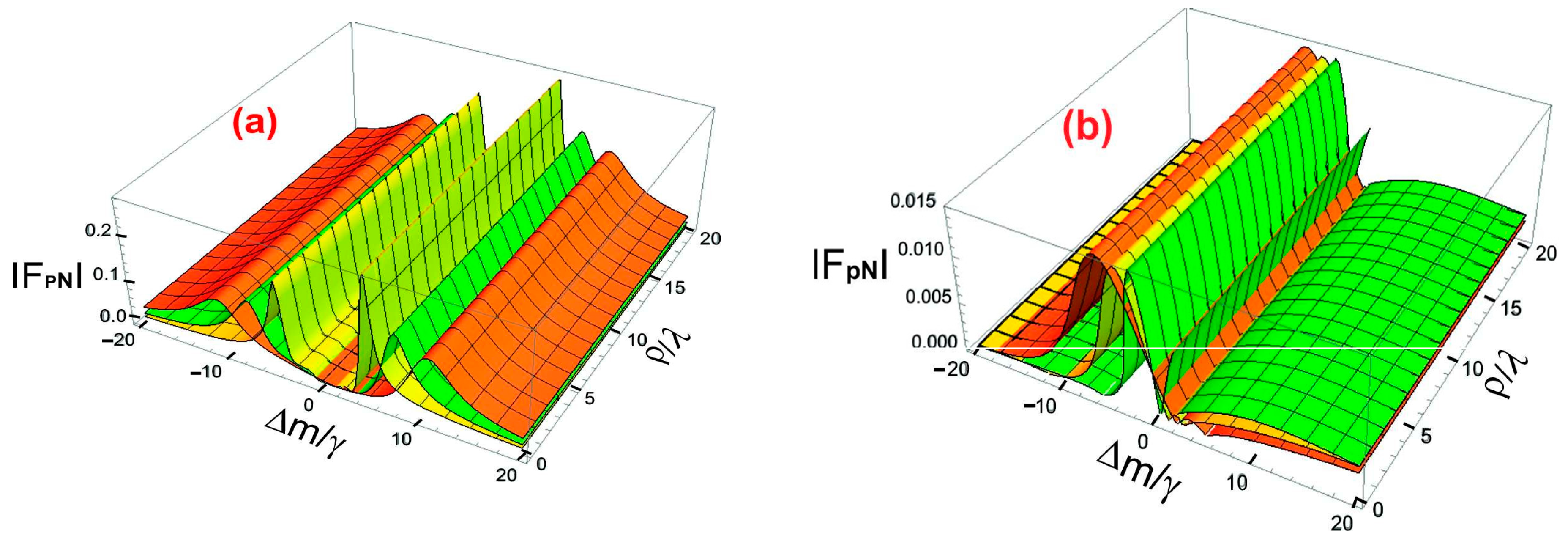
Figure 6(a) and 6(b) explore the strength of optical force resulting from various circular polarization states of the probe field. Figure 6(a) is dedicated to the left circularly polarized (LCP) field, while FIG 6(b) focuses on the right circularly polarized (RCP) field. Each graph illustrates the magnitude of optical force as a function of normalized detuning (Δm/λ) and transverse radial coordinate (ρ/λ) across different values of the control field strength ∣Ωc∣. The control field plays a crucial role in determining the magnitude of optical forces within the chiral medium. In FIG 6(a), the plots are traced for magnitude of optical force in an electromagnetically chiral medium for left circular polarized vector field along the detuning parameter ∆m/γ and transverse radial coordinate ρ/λ in 2D space. Also the magnitude of left circular polarized vector field of optical force is a function of Rabi frequency control field |Ωc|. The horizontal axis displays the detuning parameter Δm/λ, which affects the resonance conditions within the medium. The vertical axis shows the normalized radial coordinate ρ/λ, illustrating how the optical force changes radially from the beam axis. The color-coded optical force curves indicate different intensities of the control field |Ωc|. The peak of the orange curve corresponds to a control field strength of ∣Ωc∣=2γ, the yellow curve peak represents a control field strength of ∣Ωc∣=3γ, and the peak of the green curve corresponds to a control field strength of ∣Ωc∣=4γ, respectively. In this case, the strength of control field |Ωc| varies/increases from 2γ to 4γ for left circular polarized vector field of optical force. The optical force exhibits sharp peaks at specific values of Δm/λ, indicating resonance effects. These peaks shift slightly as ∣Ωc∣ increases, suggesting that the control field alters the resonance conditions. The optical force also varies with the distance from the beam axis, being strongest near the center (ρ/λ≈0) and gradually decreasing as normalized radial coordinate ρ/λ increases. This indicates that the optical force is more concentrated around the beam’s core, which is crucial for optical trapping applications. Increasing the strength of the control field ∣Ωc∣ results in an overall rise in force magnitude from 2γ to 4γ for the left circularly polarized vector field of optical force across all ρ/λ values. However, this effect is more significant near the resonance conditions in Δm/λ. The magnitude of optical force in an electromagnetically chiral medium for RCP field of detuning ∆m/γ and normalized radial coordinate ρ/λ varies from 0pN to 0.2pN as shown in FIG 6(a). In FIG 6(b), the plots are traced for magnitude of optical force in an electromagnetically chiral medium for RCP field along ∆m/γ and ρ/λ in 2D space. Also the magnitude of RCP field of optical force is a function of Rabi frequency control field |Ωc|. The axes and overall setup are the same as in FIG. 6(a), but here the probe field is RCP instead of LCP. In this scenario, the strength of the control field |Ωc| ranges from 2γ to 4γ, with the color code reversed for the right circular polarized vector field of optical force compared to FIG. 6(a). The peak of the optical force curve for |Ωc|=2γ is represented by the green color code, while the yellow color code peak curve indicates the strength of the control field. The orange color code peak curve corresponds to the control field strength at |Ωc|=3γ and |Ωc|=4γ, respectively. In this case, |Ωc| varies from 2γ to 4γ for RCP field of optical force. The optical force shows distinct peaks at certain values of Δm/λ, resembling the resonance behavior found with LCP. These peaks shift with an increase in ∣Ωc∣ from 2γ to 4γ for the RCP field of the optical force, indicating that the control field impacts the resonance conditions. The optical force is strongest near the center of the beam (ρ/λ≈0), with a gradual decrease outward, demonstrating radial symmetry. However, the force distribution is slightly different from what is seen in FIG. 6(a) due to polarization effects. As shown in FIG. 6(a), increasing the strength of the control field from ∣Ωc∣ 2γ to 4γ enhances the magnitude of the optical force. While the peak positions shift, the overall pattern of the force still differs from the LCP scenario. The magnitude of optical force in electromagnetically chiral medium for right circular polarized field detuning ∆m/γ and ρ/λ increases from 0pN to 0.015pN as shown in FIG 6(b). The comparison of FIG. 6(a) and FIG. 6(b) shows that the optical force's magnitude is influenced by polarization. The patterns of optical force in FIG. 6(a) (LCP) and FIG. 6(b) (RCP) are similar, yet not identical. The force magnitude varies slightly at certain Δm/λ values, indicating a polarization-dependent response from the chiral medium. This difference arises from the interactions between chiral light and matter, where the medium reacts distinctly to left- and right-handed circularly polarized light. Additionally, a reversed color mapping can be seen as the control field strength ∣Ωc∣ increases. In FIG. 6(a) (LCP case), stronger optical forces are represented by green (∣Ωc∣=4γ), while in FIG. 6(b) (RCP case), the strongest forces appear in orange (∣Ωc∣=4γ). This indicates that although the force profiles exhibit similarities, there remains an inherent asymmetry in how the chiral medium responds to the two types of polarization. The resonance peaks in Δm/λ do not align perfectly between the two figures, suggesting that the optical force behaves differently based on whether the probe field is LCP or RCP, thus highlighting the influence of chirality on force dynamics. In both scenarios, the optical force is stronger near the center of the beam and diminishes as normalized radial coordinate ρ/λ increases. However, the rate of decrease in force is slightly different between the LCP and RCP cases, implying that chirality also impacts the radial force profile.
4. Conclusion
In summary, the control and modification of the vector fields of optical force both for left and right circular polarized fields are achieved through variation and strength of control derived field applied at the level of an electromagnetically chiral media. The probe coherence term and associated susceptibility and polarizability for an electromagnetically chiral media are assessed using the density matrix approach. The polarizability is used to compute the energy and momenta densities. In an electromagnetically chiral medium, the left and right circularly polarized vector fields of the optical force are exactly connected to the energy and momenta densities. Using spatial coordinates, probe and control field detuning, and decay rates, the variation and dependence of the left and right circularly polarized optical force vector fields are examined and tracked. Optical force’s left and right circularly polarized vector fields are functions of magnetic, orbital as well as spin quantum numbers. The measured maximum magnitude of optical force for the left and right circular polarized vector fields with variation in the probe detuning of control field’s p/γ and normalized spatial coordinate z/λ is 0.04pN and 0.003pN respectively. For both left and right circular polarized vector fields, the maximum optical force magnitude varies according to the detuning of control field’s Δm/γ and normalized radial coordinate ρ/λ is respectively 0.2pN and 0.015pN. The direction and strength (magnitude) of the optical force increases with the sign and values of the orbital quantum number (topological charge) along with their corresponding orbital angular momentum (OAM) in chiral medium. The findings point to possible uses in the fields of high precision sensing, quantum information, fundamental optics, atomic physics, optomechanics, material science, nano science, quantum physics, radar, waveguide, antennas, and optical tweezers technology.
Author Contributions
Asghar Ali, Jeong Ryeol Choi and Nassir Saad Alarifi proposed and supervised the project; Iqbal Hussain,, Mostafa R. Abukhadra Designed and performed the experiments. Asghar Ali and Iqbal Hussain analyzed the data and wrote the manuscript. All authors participated in the discussions and provided input on the manuscript.
Funding
This work was supported by the National Research Foundation of Korea (NRF) grant funded by the Korea government (MSIT) (No.: NRF-2021R1F1A1062849). Researchers Supporting Project number (RSPD2024R804), King Saud University, Riyadh, Saudi Arabia, supported this research
Additional Information Competing Interests
The authors declare that they have no competing interests.
Data availability
The data supporting the findings of this study are available from Dr. Asghar Ali, Department of Physics, The University of Lahore. Requests for data should be directed to Dr. Asghar Ali at asghar246@gmail.com.
Acknowledgment
This manuscript is part of Ph.D thesis of the first author. This research was supported by Researchers Supporting Project number (RSPD2024R804), King Saud University, Riyadh, Saudi Arabia and National Research Foundation of Korea (NRF) by the Korea government (MSIT) (No.: NRF-2021R1F1A1062849).
References
- Jinsheng Lu, Hangbo Yang, Lina Zhou, Yuanqing Yang, Si Luo, Qiang Li, and Min Qiu, Physical review letters 118 (4), 043601 (2017).
- Amaury Hayat, JP Balthasar Mueller, and Federico Capasso, Proceedings of the National Academy of Sciences 112 (43), 13190 (2015).
- Albert Guijarro and Miguel Yus, The origin of chirality in the molecules of life: a revision from awareness to the current theories and perspectives of this unsolved problem. (Royal Society of Chemistry, 2008).
- TL Gustavson, AP Chikkatur, AE Leanhardt, A Görlitz, Subhadeep Gupta, DE Pritchard, and Wolfgang Ketterle, Physical Review Letters 88 (2), 020401 (2001).
- Johan Nilsson, Mikael Evander, Björn Hammarström, and Thomas Laurell, Analytica chimica acta 649 (2), 141 (2009).
- Jaydev P Desai, Anand Pillarisetti, and Ari D Brooks, Annu. Rev. Biomed. Eng. 9, 35 (2007).
- Jeffrey R Moffitt, Yann R Chemla, Steven B Smith, and Carlos Bustamante, Annu. Rev. Biochem. 77, 205 (2008).
- Giovanni Volpe, Onofrio M Maragò, Halina Rubinsztein-Dunlop, Giuseppe Pesce, Alexander B Stilgoe, Giorgio Volpe, Georgiy Tkachenko, Viet Giang Truong, Síle Nic Chormaic, and Fatemeh Kalantarifard, Journal of Physics: Photonics 5 (2), 022501 (2023).
- Maria Dienerowitz, Michael Mazilu, and Kishan Dholakia, Journal of nanophotonics 2 (1), 021875 (2008).
- Lucien P Ghislain and Watt W Webb, Optics Letters 18 (19), 1678 (1993).
- Chunhua Dong, Victor Fiore, Mark C Kuzyk, and Hailin Wang, Science 338 (6114), 1609 (2012).
- Tom P Purdy, Robert W Peterson, and CA Regal, Science 339 (6121), 801 (2013); Yi-Wen Hu, Yun-Feng Xiao, Yong-Chun Liu, and Qihuang Gong, Frontiers of Physics 8, 475 (2013); Wen Zhao, Sheng-Dian Zhang, Adam Miranowicz, and Hui Jing, Science China Physics, Mechanics & Astronomy 63 (2), 224211 (2020); Jun-Hao Liu, Guangqiang He, Qin Wu, Ya-Fei Yu, Jin-Dong Wang, and Zhi-Ming Zhang, Optics Letters 45 (18), 5169 (2020); Xueyue Zhang, Qi-Tao Cao, Zhuo Wang, Yu-xi Liu, Cheng-Wei Qiu, Lan Yang, Qihuang Gong, and Yun-Feng Xiao, Nature Photonics 13 (1), 21 (2019).
- Oǧuz Derın, Muharrem Karaaslan, Emın Ünal, Faruk Karadağ, Olcay Altintaş, and Oğuzhan Akgöl, Bulletin of Materials Science 42 (4), 191 (2019).
- Imran M Mirza and John C Schotland, JOSA B 35 (5), 1149 (2018).
- Yifei Mao, Yun Zheng, Can Li, Lin Guo, Yini Pan, Rui Zhu, Jun Xu, Weihua Zhang, and Wengang Wu, Advanced materials 29 (19), 1606482 (2017).
- Haroon Akhtar Qureshi, Muhammad Arshad Fiaz, and Muhammad Aqueel Ashraf, Advances in Materials Science and Engineering 2018 (2018).
- SB Wang and Che Ting Chan, Nature communications 5 (1), 3307 (2014).
- Tianhang Zhang, Mahdy Rahman Chowdhury Mahdy, Yongmin Liu, Jing Hua Teng, Chwee Teck Lim, Zheng Wang, and Cheng-Wei Qiu, ACS nano 11 (4), 4292 (2017).
- Gabriella Cipparrone, Alfredo Mazzulla, Alfredo Pane, Raul Josue Hernandez, and Roberto Bartolino, Advanced Materials 23 (48), 5773 (2011).
- Rongkuo Zhao, Thomas Koschny, and Costas M Soukoulis, Optics express 18 (14), 14553 (2010).
- Andrew G Mark, John G Gibbs, Tung-Chun Lee, and Peer Fischer, Nature materials 12 (9), 802 (2013).
- Fan Bai, Junhong Deng, Mengsu Yang, Junxue Fu, Jack Ng, and Zhifeng Huang, Nanotechnology 27 (11), 115703 (2016).
- Nicole Cathcart and Vladimir Kitaev, ACS nano 5 (9), 7411 (2011).
- Hye-Eun Lee, Hyo-Yong Ahn, Jungho Mun, Yoon Young Lee, Minkyung Kim, Nam Heon Cho, Kiseok Chang, Wook Sung Kim, Junsuk Rho, and Ki Tae Nam, Nature 556 (7701), 360 (2018).
- Alexander Y Zhu, Wei Ting Chen, Aun Zaidi, Yao-Wei Huang, Mohammadreza Khorasaninejad, Vyshakh Sanjeev, Cheng-Wei Qiu, and Federico Capasso, Light: Science & Applications 7 (2), 17158 (2018).
- M Decker, R Zhao, CM Soukoulis, Stefan Linden, and M Wegener, Optics letters 35 (10), 1593 (2010).
- E Plum, VA Fedotov, and NI Zheludev, Journal of Optics A: Pure and Applied Optics 11 (7), 074009 (2009).
- C Menzel, C Helgert, C Rockstuhl, E-B Kley, A Tünnermann, T Pertsch, and F Lederer, Physical review letters 104 (25), 253902 (2010).
- Fengli Gao, Maozhong Sun, Wei Ma, Xiaoling Wu, Liqiang Liu, Hua Kuang, and Chuanlai Xu, Advanced Materials 29 (18), 1606864 (2017).
- Si Li, Liguang Xu, Wei Ma, Xiaoling Wu, Maozhong Sun, Hua Kuang, Libing Wang, Nicholas A Kotov, and Chuanlai Xu, Journal of the American Chemical Society 138 (1), 306 (2016).
- Marco Esposito, Vittorianna Tasco, Massimo Cuscuna, Francesco Todisco, Alessio Benedetti, Iolena Tarantini, Milena De Giorgi, Daniele Sanvitto, and Adriana Passaseo, Acs Photonics 2 (1), 105 (2015); Marco Esposito, Vittorianna Tasco, Francesco Todisco, Massimo Cuscunà, Alessio Benedetti, Daniele Sanvitto, and Adriana Passaseo, Nature communications 6 (1), 6484 (2015).
- Affar S Karimullah, Calum Jack, Ryan Tullius, Vincent M Rotello, Graeme Cooke, Nikolaj Gadegaard, Laurence D Barron, and Malcolm Kadodwala, Advanced Materials 27 (37), 5610 (2015).
- Christophe Caloz and Ari Sihvola, IEEE Antennas and Propagation Magazine 62 (1), 58 (2020).
- Francisco J Rodríguez-Fortuño, Nader Engheta, Alejandro Martínez, and Anatoly V Zayats, Nature communications 6 (1), 8799 (2015); Farid Kalhor, Thomas Thundat, and Zubin Jacob, Applied Physics Letters 108 (6) (2016); Tun Cao, Libang Mao, Dongliang Gao, Weiqiang Ding, and Cheng-Wei Qiu, Nanoscale 8 (10), 5657 (2016).
- JB Pendry, Science 306 (5700), 1353 (2004).
- Meng Qiu, Lei Zhang, Zhixiang Tang, Wei Jin, Cheng-Wei Qiu, and Dang Yuan Lei, Advanced Functional Materials 28 (45), 1803147 (2018); Joel T Collins, Christian Kuppe, David C Hooper, Concita Sibilia, Marco Centini, and Ventsislav K Valev, Advanced Optical Materials 5 (16), 1700182 (2017); Si Li, Juan Liu, Naomi S Ramesar, Hendrik Heinz, Liguang Xu, Chuanlai Xu, and Nicholas A Kotov, Nature Communications 10 (1), 4826 (2019); Guixin Li, Shuang Zhang, and Thomas Zentgraf, Nature Reviews Materials 2 (5), 1 (2017); Changlong Hao, Rui Gao, Yue Li, Liguang Xu, Maozhong Sun, Chuanlai Xu, and Hua Kuang, Angewandte Chemie 131 (22), 7449 (2019).
- Innem VAK Reddy, Alexander Baev, Edward P Furlani, Paras N Prasad, and Joseph W Haus, Acs Photonics 5 (3), 734 (2018).
- Mehdi Veysi, Caner Guclu, and Filippo Capolino, JOSA B 32 (2), 345 (2015).
- Konstantin Y Bliokh and Franco Nori, Physics Reports 592, 1 (2015).
- N. Simpson, K. Dholakia, L. Allen, M.Padgett,(1997), Opt. Lett. 22, 52[Cross Reference]. .
- AT O'neil, I MacVicar, L Allen, and MJ Padgett, Physical review letters 88 (5), 053601 (2002).
- M Babiker, CR Bennett, DL Andrews, and LC Dávila Romero, Physical review letters 89 (14), 143601 (2002).
- Fumito Araoka, Thierry Verbiest, Koen Clays, and Andre Persoons, Physical Review A 71 (5), 055401 (2005).
Figure 1.
Four level atomic configuration for chiral medium.
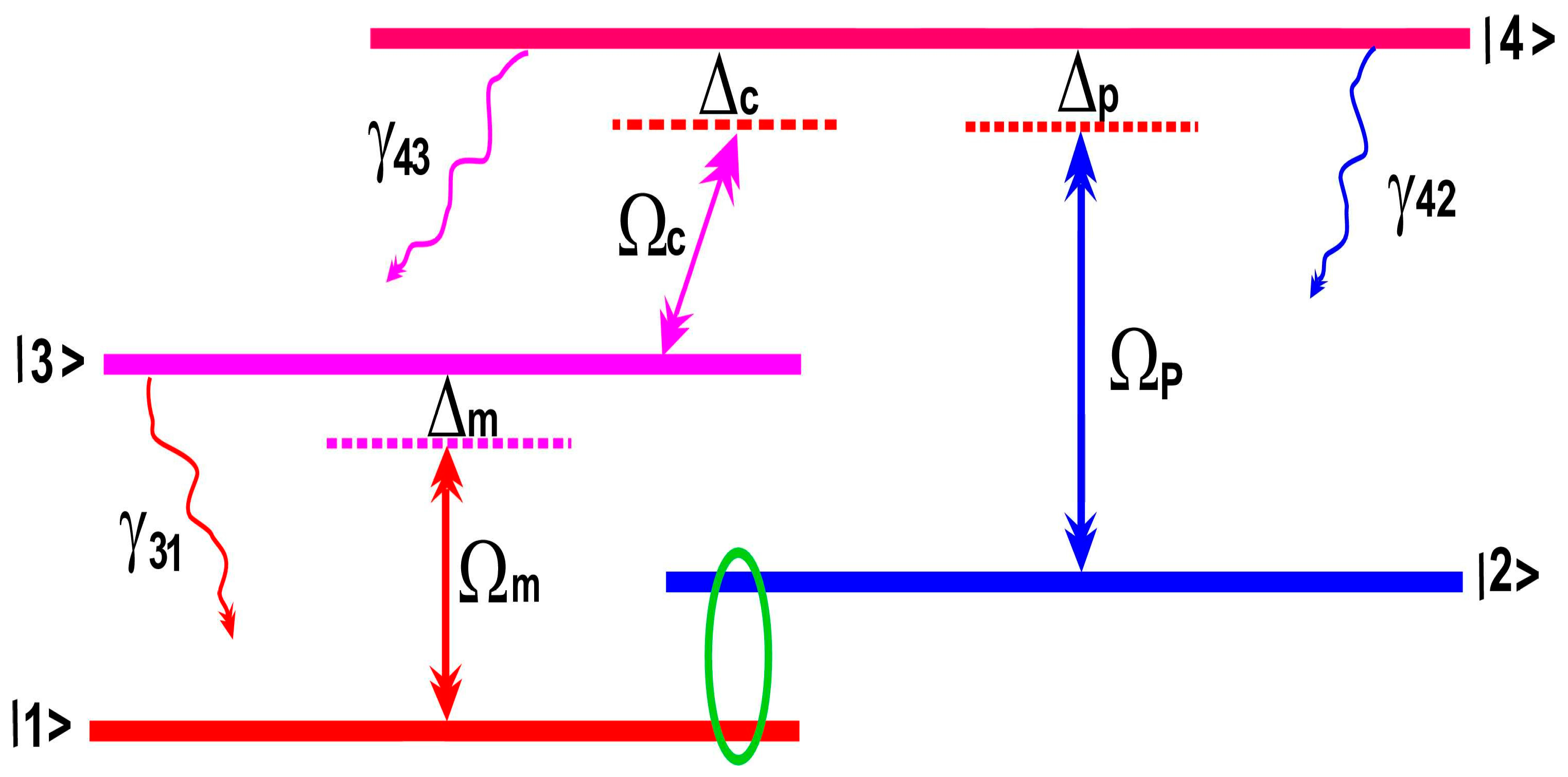
Figure 2.
a-h): Optical forces in electromagnetically chiral medium for left circular polarization probe fields (LCP) and right circular polarization probe fields (RCP). Optical forces vectors field arrows distribution function versus along spatial coordinate’s x/λ, y/λ, and z/λ for left circular polarization probe fields (LCP) as well as right circular polarization probe fields (RCP). The common parameters for optical forces LCP and RCP vector field arrows distribution are: γ43 = 1γ, γ42 = 1γ, γ32 = 1γ, γ31 = 1γ, ∆p = 0.2γ, ∆c = 0γ, ∆m = 0γ, and |Ωc| = 2γ. The chosen parameters for LCP and RCP figures (a-d) are: (a) l=+2, m=0,1, s=1, (b) l=−2, m=0,1, s=1, (c) l=+4, m=0,1, s=1 (d) l=−4, m=0,1, s=1.
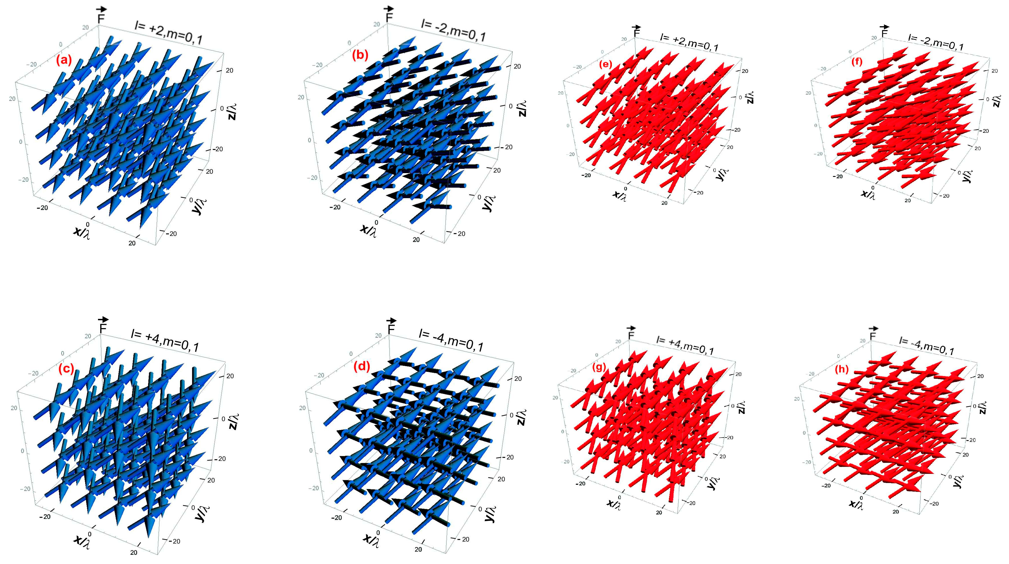
Figure 3.
a-h): Optical forces in electromagnetically chiral medium for left and right circular polarization probe fields. Optical forces versus vectors field of optical forces distribution function vectors arrow along three coordinates ∆c/γ, ∆m/γ, and ∆p/γ for left and right circular polarization probe fields. The common parameters for LCP and RCP optical forces and distribution of arrows are: γ43 = 1γ, γ42 = 1γ, γ32 = 1γ, γ31 = 1γ, , φ = 0, and |Ωc| = 2γ. The chosen parameters for figures (a-d) are: (a) l=+2, m=0,1, s=1, (b) l=−2, m=0,1, s=1, (c) l=+4, m=0,1, s=1, (d) l=−4, m=0,1, s=1.
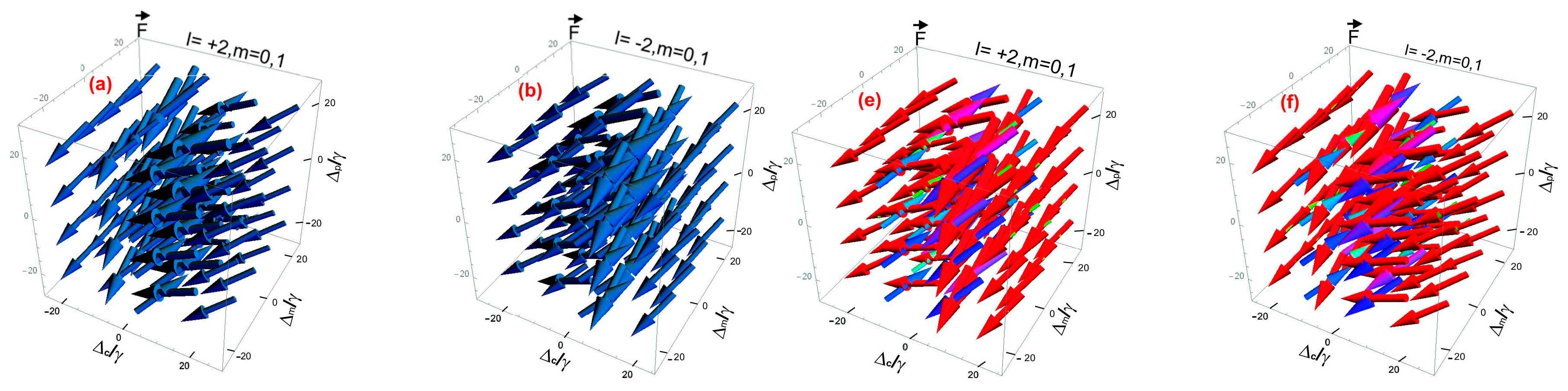
Figure 4.
(a-h): Optical forces in electromagnetically chiral medium for left circular polarization probe fields (blue arrows) and right circular polarization field (red arrows). Optical forces versus vectors field of optical forces distribution function vectors arrow along three coordinate’s γ32, γ42, and z/λ for left and right circular polarization probe fields. The common parameters for LCP and RCP optical forces distribution arrows are: γ43 = 1γ, γ31 = 1γ, ∆p = 0.2γ, ∆c = 0γ, ∆m = 0γ, φ = 0, and |Ωc| = 2γ. The chosen parameters for figures (a-d) are: (a) l=+2, m=0,1, s=1, (b) l=−2, m=0,1, s=1, (c) l=+4, m=0,1, s=1, (d) l=−4, m=0,1, s=1.
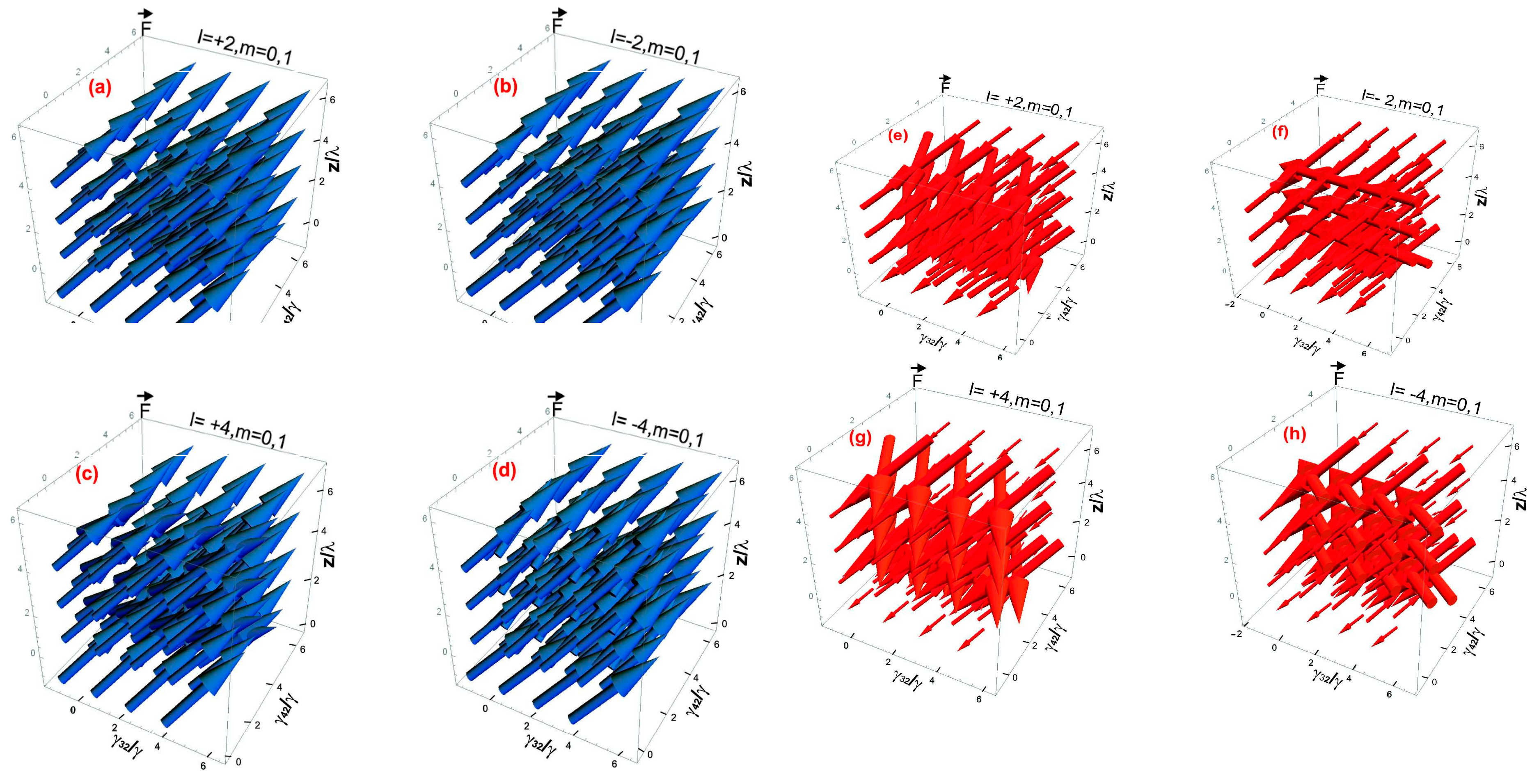
Figure 5.
a-b): Magnitude of optical forces in electromagnetically chiral medium, for (a) left and for (b) right circular polarization probe field versus ∆p/λ and z/λ. The chosen parameters for magnitude of optical forces for left circular polarization probe field are: |Ωc|=3γ (orange), |Ωc|=4γ (yellow), and |Ωc|=5γ (green). The chosen parameters for magnitude of optical forces for right circular polarization probe field are: |Ωc|=3γ (green), |Ωc|=4γ (yellow), |Ωc|=5γ (orange). The common parameters are: γ43 = γ42 = γ32 = γ31 = 1γ, ∆c = ∆m = 0γ, l=1, s=1, m=1, ρ=10, and ϕ=π/4.
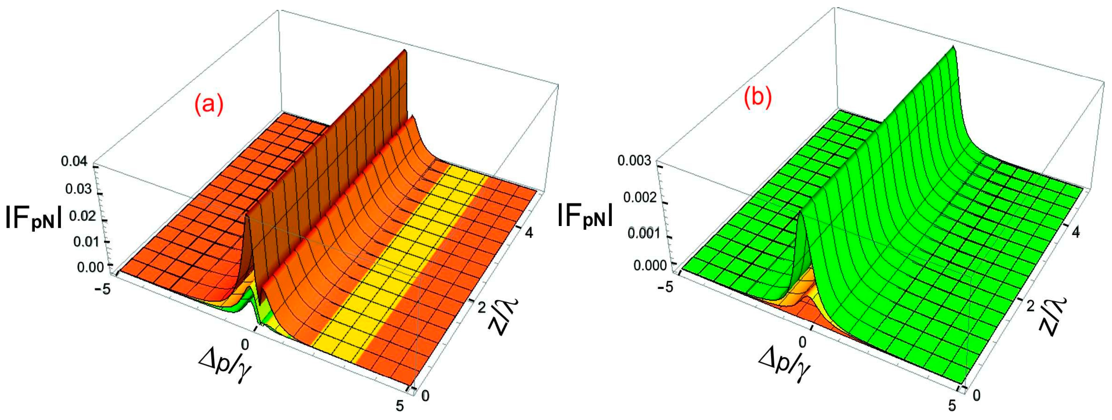
Figure 6.
a-b): Magnitude of optical forces in electromagnetically chiral medium, (a) for left and (b) for right circular polarization probe field versus ∆m/λ and ρ/λ. The chosen parameters for left circular polarization probe field are |Ωc|=2γ (orange), |Ωc|=3γ (yellow), and |Ωc|=4γ (green). (c) The chosen parameters for right circular polarization probe field are |Ωc|=2γ (green), |Ωc|=3γ (yellow), |Ωc|=4γ (orange). The common parameters are γ43 = γ42 = γ32 = γ31 =1γ, ∆c = 0, ∆p = 0.2γ, z=20, l=1, s=1, m=1, and ϕ=π/4.
Disclaimer/Publisher’s Note: The statements, opinions and data contained in all publications are solely those of the individual author(s) and contributor(s) and not of MDPI and/or the editor(s). MDPI and/or the editor(s) disclaim responsibility for any injury to people or property resulting from any ideas, methods, instructions or products referred to in the content. |
© 2025 by the authors. Licensee MDPI, Basel, Switzerland. This article is an open access article distributed under the terms and conditions of the Creative Commons Attribution (CC BY) license (https://creativecommons.org/licenses/by/4.0/).
Copyright: This open access article is published under a Creative Commons CC BY 4.0 license, which permit the free download, distribution, and reuse, provided that the author and preprint are cited in any reuse.


