
Submitted:
21 February 2025
Posted:
24 February 2025
You are already at the latest version
Abstract
Energy storage and conversion is a critical connection between the stages of energy generation and use. Conventional fossil fuels are a natural and unsustainable energy storage medium with finite reserves and infamous environmental concerns, necessitating a better alternative for storing and using green and renewable energies in the future. Fuel cells produce heat and electricity as a result of the electrochemical process that occurs when oxygen and hydrogen combine to make water. A possible method of supplying energy to rural regions without connection to the public grid or where the expense of wiring and transmitting power is prohibitive is through the use of fuel cells. Furthermore, it has grown in popularity because of the desire for clean energy, the scarcity of fossil fuel supplies, and the ability to generate electricity without the usage of any moving mechanical components. Furthermore, fuel cells can be used as an energy source in applications that require consistent electrical power, such as distributed systems, power generation facilities, and uninterruptible power supplies (UPS). The current study analyses the fundamental structure, function, and applications of the numerous fuel cell technologies that are now available. In this study, we focus on current breakthroughs in fuel cell technology.
Keywords:
Fuel Cell Technologies
; Polymer Electrolyte
; Membrane Fuel Cells (PEMFCs)
; Solid Oxide Fuel Cells (SOFCs)
; Direct Methanol Fuel Cells (DMFCs)
; Fuel Cell Applications
1. Introduction
Energy plays a pivotal role in shaping a country's economy, infrastructure, transportation, and overall standard of living. However, a critical issue faced globally is the imbalance between energy availability and consumption, which exacerbates environmental and economic challenges. Currently, all countries rely heavily on fossil fuels for energy generation—resources that are inherently finite and unsustainable. To meet the escalating energy demands of a growing global population, it is essential to transition towards alternative, sustainable energy sources that do not harm the environment [(Hosseini, Andwari, et al., 2013), (Granovskii et al., 2007)].
In recent decades, the United States has taken significant steps to reduce petroleum dependency and mitigate the environmental impacts of the transportation sector. One of the primary challenges associated with the current energy landscape is the depletion of non-renewable fossil fuels, which not only threatens the sustainability of the energy industry but also contributes to broader environmental issues such as the greenhouse effect [(Derbeli et al., 2018), (Hosseini, Wahid, et al., 2013)]. The use of fossil fuels remains substantial today, and projections indicate that by 2050, they will still account for approximately 75% of global energy production (Eriksson & Grey, 2017).
As depicted in Figure 1, the decline in gas reserves from 2010 to 2020 illustrates this trend, highlighting the steady increase in consumption over time while the remaining reserves continue to dwindle. Notably, the consumption growth rate remains consistent at 8% annually, underscoring the urgency of finding alternative solutions.
This steady depletion of fossil fuels poses a serious challenge, forcing many industries to scale back production due to limited gas supplies. In this case, fuel cells are emerging sources of energy that require special attention. A fuel cell is an electrochemical device which uses the chemical energy of a fuel and transforms it into electrical energy directly. Fuel cells are different from traditional combustion-based heat engines in that they have fewer processes and steps involved in energy production as fuel cells have a direct, more efficient, and sustainable conversion method.
The negative impact of using conventional sources for energy generation, especially those relying on combustion, is now clear. It contributes to some of the world’s biggest issues today which include climate change, depletion of ozone layer, acid rain, and continuously destroying plant ecosystems. Also, these methods are reliant on fossil fuels which are scarce, making the problem worse. This is done while using the fuel cells as they are cleaner and more efficient in converting energy. Also It is possible to integrate fuel cells with renewable sources such as hydrogen to further promote sustainability and energy security.
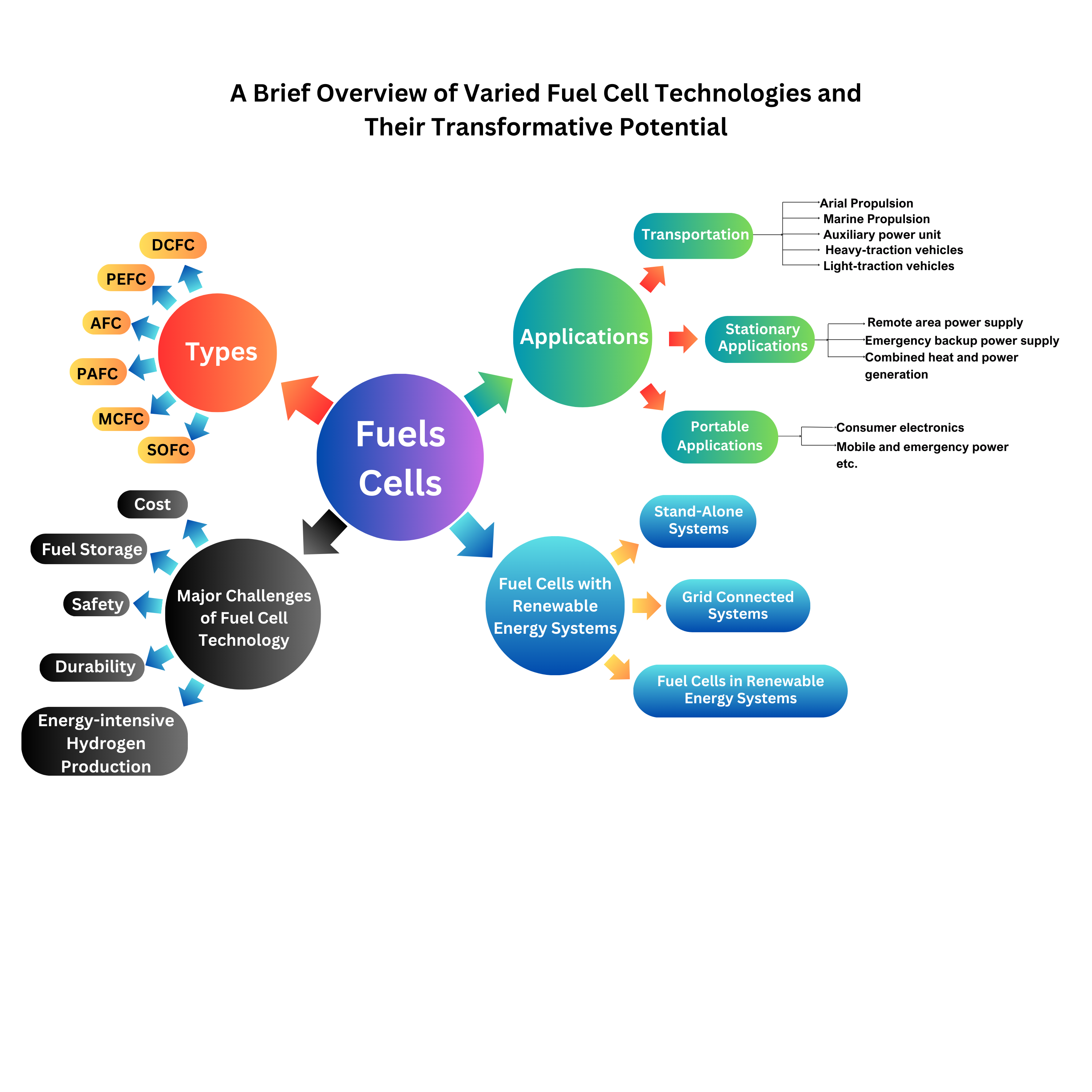
Due to their applicability, fuel cells are regarded as a fundamental component of the future energy systems. They can be employed across various applications, including portable, stationary, and transportation power generation. Their quiet operation, devoid of noise and vibration, further contributes to their appeal. In essence, fuel cells represent one of the most efficient, clean, and adaptable methods of converting chemical energy into electricity.
As seen in Table 1, while diesel engines boast the highest capacity, fuel cells are unparalleled in efficiency, achieving up to 85%. Furthermore, the capital cost per kilowatt for fuel cells is relatively low, making them a cost-effective solution in the long run. For these reasons, the use of fuel cells is on the rise, becoming an increasingly prominent topic in power generation discussions.
In this paper, we will explore the current state of fuel cell technology, examine the various types of fuel cells, and discuss their applications in different sectors of the energy market.
2. Energy Storage System
An Energy Storage System (ESS) is a device or a set of interconnected devices designed to store energy for later use. The storage capacities of ESS are typically measured in terms of energy (MWh) and power (MW), reflecting their ability to hold and release energy. There are various methods of storing energy, including thermal, mechanical, chemical, electrochemical, electrical, and magnetic fields. Additionally, energy can be stored in hybrid systems that combine two or more of these methods.
As shown in Figure 2, the classification of ESS encompasses a wide range of technologies, each with its unique mechanisms for energy storage. According to Table 2, these systems are categorized based on the specific form of energy they store, offering distinct advantages depending on their application. Before deployment, over 45 types of ESS are compared across 20 technical variables to determine the most suitable solution for a given energy storage need. This comprehensive comparison helps in understanding the strengths and limitations of each type, ensuring optimal selection and implementation.
3. Working Principle of Fuel Cell
Fuel cells are efficient devices that turn the inherent chemical energy of fuel (hydrogen) into electricity for a variety of applications. Fuel cells emit only heat and water vapour, making them a clean energy source. If the system is supplied with fuel and oxygen, energy can be generated continuously. Fuel cell efficiency is around 20-30% greater than typical combustion engines, and they operate extremely silently owing to the lack of moving parts. Fuel cells are of different types based on the selection of electrolyte. Apart from the electrolyte, the other main parts include cathode, anode and load, an external circuit. Hydrogen is supplied at the anode and is divided into positive ions and negative ions or electrons through oxidation. Whereas oxidants are supplied to the cathode from the air. The protons or positive ions traverse the electrolytic medium, separating anode and cathode plates, and the electrons from the anode come through the external circuit towards the cathode. Consequently, reduction reaction takes place at cathode and generates water from the interaction among cations, electrons and O2. This transfer of electron from anode to cathode results in the current output from fuel cell (Sazali et al., 2020).
Demonstrated by the Figure 3, the fuel cell converts hydrogen and oxygen into electricity, producing water and heat as byproducts. The whole process can be considered as a reversed electrolysis reaction and showed in following equations:
Anode: 2H2 → 4H+ + 4e−
Cathode: O2 + 4e− + 4H+ → 2H2O
Various types of fuel cells employ different materials, yet the fundamental reactions remain same between hydrogen and oxygen. The electrolytes play a pivotal role in preventing short circuits by establishing insulation and aversion of electron conductivity, only allowing ionic transportation between electrodes. (Guaitolini & Fardin, 2018) Despite its high theoretical efficiency at approximately 83%, further improvement can be attained by considering thinner electrolyte layers and electrodes with flat and porous surfaces (Mekhilef et al., 2012).
4. Types of Fuel Cells
Many geometries, such as planar, tubular, radial, and others, as well as a variety of fuels and electrolyte charge carriers, may be used in the construction of fuel cells, which can include single chamber, dual chamber, and other configurations (Turco et al., 2016). The charge carrier, operating temperature, and kind of electrolyte used in the cells are the initial elements that distinguish different types of fuel cells (Office, n.d). Fuel cells are currently being developed in a number of configurations, each with its own set of advantages, limitations, and potential applications. Figure 4 shows the types of fuel cells that have been researched and developed:
4.1. Direct Carbon Fuel Cell (DCFC)
Direct Carbon Fuel Cells (DCFCs) represent a pioneering approach to energy conversion, using solid carbon as fuel and directly transforming its chemical energy into electrical energy through electrochemical oxidation (Giddey et al., 2012). Unlike traditional heat engines, DCFCs achieve higher energy conversion efficiency, simplify system design, and reduce costs. A remarkable feature of these cells is their nearly 100% thermodynamic efficiency, positioning them as an attractive innovation due to both their high energy efficiency and the abundance of carbon as a fuel source. Among various types of DCFCs, the Direct Carbon Solid Oxide Fuel Cells (DC-SOFC) and Direct Carbon Molten Carbonate Fuel Cells (DC-MCFC) are particularly noteworthy. The performance and power densities of these fuel cells are significantly influenced by the carbon's quality and structure, which also affect electrode kinetics during the direct oxidation process.
The Figure 5 depicts the process in which DCFCs operate carbon sources are injected into the system for oxidation. The output of this process is high-purity CO2 along with electrons that can be utilized for electricity generation. Electricity is produced from the flow of electrons while the oxidation reactions depend on the contribution of air and oxygen, making the system efficient. This process of energy conversion is simplified and yields high efficiency, which enhances the promise of DCFC technology as a viable option for sustainable energy. Comprehensive summary analysis and experimental approaches regarding the performance of DCFCs are captured in Table 3. These analyses are aimed on the performance of variety of electrolytes and their contribution in efficiency of DCFC, which can help to optimize DCFC technologies for better performance.
Recent progress by Ozalp and colleagues in 2022 tackles anode-side currents and concentrations in novel anode interfaces for improved DCFC performance. Direct Fuel Cell (DFC) technology has come a long way since 1896 and makes use of existing technologies pouring transferrable knowledge from Molten Carbonate Fuel Cells (MCFC), Solid Oxide Fuel Cells (SOFC), and Alkaline Fuels Cells (AFC) into harnessing its full potential (Rady et al.,2012). Another area with active research is the use of carbon nanoparticles which, because of their large surface area and high reactivity, could greatly impact negatively or positively be very positive to the DCFC performance. Those like Wang et al. (2021) looked closely to analyze the electrochemical reactivity in molten salts and how it relates to the nanostructure of carbon. The disordered state of carbon atoms is shown to have a large impact on electron yield and the more disordered carbon atoms, the more reactive they become (Cui et al., 2021). These is more important than either surface area or purity of carbon as a contributor to Direct Fuel Cell performance.
Figure 6 illustrates the heat accumulated in the electrolyte material (NaOH) and the primary components of the Ni cell. The total heat stored in the cell is depicted by the inclined green line, emphasizing the energy management in the DCFC system. This detailed analysis contributes to the understanding of the factors that influence DCFC performance and highlights the significant progress made in the technology.
Figure 7 presents the temperature profile of a 25 kW fuel cell over time, which reveals how temperature dynamics are integral to fuel cell efficiency. As indicated by this data, DCFC development heavily depends on advancements in both the anode and anode chamber design. The reactor configuration, whether batch or flow, is influenced by the purity of the solid graphite particles (Rady et al., 2012). Extensive research on anode materials for Solid Oxide Fuel Cells (SOFCs) has shown that transition metal carbides such as tungsten, vanadium, zirconia, and titanium carbides, along with nickel and carbon, outperform traditional graphite anodes. Among these, vanadium carbide has proven to be especially effective in activating carbon solids.
The redox processes at the anode play a crucial role in carbon activation, but anode oxidation can hinder electrochemical reactions, especially in minerals like titanium carbide (TiC), which require oxygen for oxidation and do not show a direct relationship between CO evolution and current density. Wang et al. (2021) highlight several critical research needs for molten carbonate-type DCFCs to optimize their performance. These include understanding the wetting behavior of various carbon types in melts, which varies with basicity, cation composition, and temperature; characterizing molten carbonate in reducing solutions with carbon to identify stable versus semi-stable species; and employing molecular dynamics simulations to evaluate the stability of CO-CO2 and carbon-carbonate structures in the melt. Additionally, Monte Carlo modeling is essential for analyzing the interactions between carbon particle assemblies, carbonate melt, and gas bubbles (CO2, CO), as well as the electrochemical processes, buoyant forces, and interfacial interactions. This research underscores the importance of anode material and chamber design in enhancing DCFC efficiency. While significant progress has been made, ongoing innovation is critical to fully unlocking the potential of DCFCs, and continued research is key to advancing this technology toward a sustainable energy future.
4.2. Polymer Electrolyte Fuel Cell (PEFC)
Polymer Electrolyte Fuel Cells (PEFCs) utilize a polymer electrolyte membrane as the core electrolyte material, with an electrode and a gas diffusion layer positioned on either side. These Proton Exchange Membrane Fuel Cells (PEFCs) are regarded as one of the most promising clean energy technologies due to their high energy density, environmental friendliness, and efficiency. A bibliometric review of research trends in PEFCs between 2008 and 2018 underscores the significant advancements and growing interest in this innovative field.
As illustrated in Table 4, which outlines recent research on PEFCs, substantial progress has been made in enhancing cell performance and reducing manufacturing costs, both critical factors for the growth of the fuel cell industry (OTA et al., 2016). PEFCs typically operate at temperatures below 100°C, generally ranging between 60 and 80°C. Despite a theoretical open-circuit voltage (OCV) of 1.23 V, practical operation is limited to a maximum of 1.1 V due to electrode non-equilibrium (Espinoza-Andaluz et al., 2019). Their high current densities, rapid response to load variations, and high-power densities make them particularly suitable for various applications, including vehicle power systems. The use of hydrogen as fuel, combined with the advantage of low operating temperatures, allows for quick starts and efficient performance.
This review emphasizes the vast potential of PEFCs to transform clean energy systems, showcasing ongoing research efforts aimed at optimizing performance and reducing costs. As shown in Figure 8, the design and structure of PEFCs continue to evolve, driving these advancements in the field.
A significant challenge for PEFCs is the presence of carbon monoxide (CO) in the fuel stream, which can contaminate platinum catalyst sites. To solve the above, PEFCs have to run at temperatures higher than 120° C. At the moment, fully fluorinated Teflon-based membranes- Nafion, are widely used. This research aims at preventing CO poisoning along with achieving higher operating temperatures to improve the performance and lifetime of PEFCs membranes and multifunctional polymers for more effective fuel cell polymer.
Also, the performance of PEFCs is extremely dependent on the temperature and pressure operating. Nowadays, temperature of 80° C and pressure of 1.0 Mpa is the operational limit for modern PEFCs. However, there is much more scepticism about the use of higher pressure operations. This research is very important for the all-in-one PEFC development to boost the efficiency and performance. The following reaction equations prove the electrochemical reactions in PEFCs have, as in the case of other fuels cells, the original features:
Anode: H2 (g) → 2H+ + 2e−
Cathode: (1/2) O2 (g) + 2H+ + 2e− → H2O (l)
Overall reaction: H2 (g) + (1/2) O2 (g) → H2O (l)
To fully understand the performance characteristics of PEFCs, several graphs are provided below that demonstrate the system's behavior under various conditions:
The polarization curve (voltage versus current curve) for reference conditions in Polymer Electrolyte Membrane Fuel Cells is shown in Figure 9 (Ramírez-Cruzado et al., 2020). The current for the yellow curve at the bottom which represents increasing values is shown and the green curve has decreasing values for current. Each data point has error bars corresponding to three repetitions of the measurement.
Figure 10 displays the polarization curve for temperature tests, showing voltage vs. current density (Ramírez-Cruzado et al., 2020). This graph illustrates the forward curve (increasing current) at the bottom and the backward curve (decreasing current) at the top.
Figure 11 presents the performance curve, including efficiency, current density, and power output of the PEM fuel cells (Ramírez-Cruzado et al., 2020). This graph provides critical insight into the operational characteristics of PEFCs, which are essential for further enhancing their performance. Although PEFCs could be a game changer for clean energy technologies, further exploration in enhancing the efficiency, solving the CO contamination issue, and developing substitute materials is needed to realize their full promise.
4.3. Alkaline Fuel Cell (AFC)
Alkaline Fuel Cells (AFCs) use an alkaline electrolyte, commonly potassium hydroxide, to transform hydrogen and oxygen into heat, electricity, and water. For the transportation sector, AFCs provided remarkable power and definitely led the industry. However, in the last 25 years, AFC technology has struggled with carbonation. Use of air as an oxidant causes carbon dioxide from the air to react with potassium hydroxide electrolyte resulting in bad performance (Hamada et al, 2023). Notwithstanding, AFCs continue to compete with proton exchange membrane fuel cells for supremacy given their high power densities and long life spans. AFCs, according to Ariyanfar, Ghadamian, and Roshandel (2011), can achieve industry leading efficiency of 60%, but goes up to 87% when heat and power are combined.
AFCs also have growing attention in other fields due to these attributes, refrigeration, electronic devices, and particularly electric vehicle applications. New catalysts, alternative fuels like ammonia and even exploring these fields have made AFC performance and cost effectiveness advances that promises a competetive edge in the clean energy landscape. These changes make AFCs increasingly important in the remaking of sustainable energy systems.
This review emphasizes the substantial progress AFC technology has made, highlighting ongoing innovations aimed at overcoming key challenges and improving overall performance. The continued research efforts suggest that AFCs will play a vital role in the future of sustainable energy systems, furthering their potential to meet the demands of both industrial and consumer applications. Table 5 presents a summary of research studies on AFCs, specifically focusing on electrolyte investigations and catalyst advancements. These findings highlight the continued interest and progress in enhancing AFC efficiency and mitigating issues such as carbonation.
Figure 12 provides a detailed diagram of the electrochemical reactions occurring within an AFC. The oxidation reaction (2H2 + 4OH⁻ → 4H2O + 4e⁻) at the anode generates electrons, which travel through the external circuit to the cathode. At the cathode, these electrons participate in a reduction reaction with water molecules (O2 + 2H2O + 4e⁻ → 4OH⁻) to produce hydroxide ions, completing the fuel cell’s operation.
Figure 13 and Figure 14 illustrate the cell stability under varying anode/cathode dew points. Figure 13 depicts the stability under relatively high dew points of 55/60 °C, while Figure 14 shows optimized conditions of 53/55 °C. These tests, presented by Peng et al. (2020), involve measuring cell voltage and area-specific resistance (ASR), with data recorded from cells using a PtRu/C anode and Pt/C cathode. The tests assessed the performance of an AFC under specific operating conditions, such as a cell temperature of 60°C and H2/air flow rates of 1.0 L/min. This research helps inform the optimal environmental conditions for AFC performance.
The stability of the cells with respect to anode/cathode dew points is shown in figures 13 and 14. Figure 13 shows the stability at dew points of 55/60 °C and is relatively high, while figure 14 shows optimized conditions of 53/55 °C. These tests are presented in Peng et al. (2020), where the cell voltage and area specific resistance (ASR) were recorded from the cells having a PtRu/C anode and Pt/C cathode. The tests were performed to analyze the Allied Fuel Cell (AFC) performance at given operating parameters of cell temperature of 60 degrees Celsius and H2/air flow rate of 1.0 L/min. This work contributes to establish the optimal environmental conditions of AFC operation. The history of AFCs is long, and most notably in their use in space missions. Originally, they were developed to give reliable power to the Apollo spacecraft, today AFCs still find service in space missions such as supplying power to the Space Shuttle Orbiter (Wagner and Kohnke, 2020). These cells are known for their excellent performance, especially in terms of active oxygen electrode kinetics and their ability to work at elevated temperatures and high pressures.
The performance metrics in both H2/O2 and H2/Air reactions are illustrated in Figure 15 that presents the Anion-Exchange Membrane Fuel Cell (AMFC) with 8% PTFE catalyst at the anode and 20% PTFE gas diffusion layer at the cathode. The curves show performance with varying flow rates and operational parameters which yield valuable data for AFC system optimization.
Most attention in recent years has shifted towards the land-based application of the AFCs where these fuel cells are more attractive for remote power generation due to the inexpensive components that operate close to ambient pressure and temperature using air as an oxidizer. On the other hand, these components need to have cost-effective pricing to adequately compete in the consumer and industrial markets (Sokhi et al. 2022). The feasibility of the AFC in mass-market transportation is still unclear because of the never-ending problem of CO2 induced electrolyte poisoning that needs to be regulated and mitigated properly (Vidakovic-Koch, 2016).
The implementation of carbon-based porous electrodes is an example of an advanced AFC technology that has significantly reduced costs and improved performance. As the technology continues to develop, it is metamorphosing for new applications and economic needs. This transforms AFCs to be competitive for the future of clean energy solutions.
4.4. Phosphoric Acid Fuel Cell (PAFC)
Phosphoric Acid Fuel Cells (PAFCs) use liquid phosphoric acid (H3PO4) as an electrolyte, and have emerged as the leading techniques in fuel cell commercialization. These fuel cells were first commercialized due to the notable mosaic in performance, stability, and cost effectiveness achieved during the 1970s (Gallagher et al., 2008). These cells comprise carbon paper electrodes that are plated with platinum catalyst particles and are set in a silicon carbide matrix which is immersed in pure or highly concentrated phosphoric acid. PAFCs operate between temperatures of 150°C and 210°C, although they perform best between 150°C and 200°C.
The electrochemical reactions in PAFCs include the anode reaction:
and the cathode reaction:
2H2(g)→4H++4e−
O2+4H++4e−→2H2O
Despite being less efficient in energy generation compared to other fuel cell types, PAFCs have the advantage of being resistant to carbon monoxide poisoning, making them ideal for certain applications. Operating at approximately 180°C, these cells can achieve overall efficiencies exceeding 80% when used for cogeneration, where process heat is utilized. PAFCs are commonly deployed in large vehicles such as buses and in stationary power generators, with typical output ranges from 100 to 400 kW (N. H. Behling, 2013).
Leading producers of PAFC technology include Doosan Fuel Cell America Inc. (formerly Clear Edge Power & UTC Power) and Fuji Electric, which have been at the forefront of PAFC development and commercialization.
(Oxidation) 2H2→ 4H+ + 4e−
(Reduction) O2 + 4H+ + 4e− → 2H2O

Table 7.
Summary of Research on Phosphoric Acid and Solid Acid Fuel Cells.
| Author | Type of Investigation | Electrolyte | Findings |
|---|---|---|---|
| (Cr- et al., 1983) | New Applications for PAFCs | Phosphoric Acid | Explored potential applications of PAFCs, including their use in large diesel locomotives, highlighting the opportunity to displace significant petroleum usage. |
| (Tanni et al., 2013) | Dynamic Modeling of PAFC and Power Conditioning System | Phosphoric Acid | Developed a dynamic model of a 700W PAFC system using MATLAB/Simulink, analyzing cell output voltages, losses, and AC output via inverter simulation. |
| (Tanni et al., 2013) | Dynamic Modeling of PAFC and Power Conditioning System | Phosphoric Acid | Presented a dynamic model of a PAFC system with power electronics, simulating cell output voltages, losses, and AC output, facilitating performance analysis under varying inputs. |
| (Afroze et al., 2023) | Solid Acid Proton Conductors | CsH2PO4 | Demonstrated that solid acids like CsH2PO4 exhibit high proton conductivity at elevated temperatures, making them suitable for fuel cell applications. |
| (Z. Zhang et al., 2023) | Electrode Design for Enhanced Performance | Phosphoric Acid | Introduced an electrode architecture with fibrous networks to optimize phosphoric acid distribution, achieving a 28% increase in maximum power density compared to conventional designs. |
| Lohmann et al., 2017 | Advanced Electrodes for Solid Acid Fuel Cells | CsH2PO4 | Developed stable, high-performance electrodes with minimized catalyst loading for solid acid fuel cells, enhancing efficiency and durability. |
| (Papandrew et al., 2011) | Advanced Electrodes for Solid Acid Fuel Cells | CsH2PO4 | Investigated platinum deposition on CsH2PO4 for solid acid fuel cells, revealing short-range structure and interactions with the electrolyte. |
The phosphoric acid fuel cell operates through a series of electrochemical reactions as shown in Figure 16, with hydrogen gas being oxidized at the anode and oxygen being reduced at the cathode to produce water.
Although the basic cell design of PAFCs has seen limited changes, significant advancements have been made in terms of improving cell stability, lifespan, and reducing component costs. Companies like UTC Fuel Cells have made concerted efforts to enhance these attributes, although further innovations are still necessary to improve power density and cost efficiency for PAFCs to compete economically with alternative energy sources.
Historically, the introduction of carbon black and graphite as materials for cell construction in the late 1960s replaced the more expensive gold-plated tantalum hardware. These new materials provided greater stability, and the use of high-surface-area graphite allowed for a substantial reduction in platinum loading while maintaining electrode performance. Despite progress, there are still hurdles to overcome including platinum dissolution and carbon corrosion occurring at cell voltages over 0.8V.
The creation of PTFE bounded porous electrodes in combination with platinum black in the mid 1960s anchored PAFC design. Platinum loading was about 9mg Pt/cm² at the start, but efficiency advancements have been made over time and the requirement has been reduced dramatically. For instance, modern electrodes use about 0.10mg Pt/cm² at the anode and 0.50mg Pt/cm² at the cathode.
Conductivity of different acids such as HCl, HNO3, H2SO4 and H3PO4 affects the efficacy of PAFCs, as seen in Figure 17 which shows the way the conductivity of these acids changes with concentration. HCl and HNO3 have a conductivity maxima of roughly 0.8 S/cm at around 20-30wt%, while H3PO4 has a maximum of 0.2 S/cm at a concentration of 30%. In order to optimize the efficacy of PAFCs, this is essential because the conductivity of the electrolyte directly impacts the performance of the cell.
Current research targets the operating temperature and concentration of phosphoric acid to over 200°C (392°F) with 100% H3PO4 acid concentration. This approach was demonstrated by UTC Fuel Cells and serves to improve system efficiency while also increasing compatibility with hydrocarbon reformers.
4.5. Molten Carbonate Fuel Cell (MCFC)
A Molten Carbonate Fuel Cell (MCFC) has a molten carbonate salt mixture as an electrolyte that is stored in a beta-alumina solid electrolyte (BASE) ceramic matrix. This matrix is porous and chemically inert to MCFC. The fuel cell temperature currently ranges from 550–650°C but may reach up to 600–700°C in the near future (Venkataraman & Farooque, 2009). These high-temperature fuel cells were specifically designed for large-scale applications such as coal-, gas-, and biogas-fired power plants, as well as military, industrial, and utility sectors (Fuller & Gallagher, 2008). Figure 18 illustrates the structure of a typical molten carbonate fuel cell.
One of the key advantages of MCFCs is their resistance to carbon monoxide poisoning, making them highly effective when using fuels that contain carbon monoxide. Additionally, MCFCs can efficiently extract hydrogen from a variety of fuels, either via internal or external reformers. This capability makes them particularly attractive for use with coal-based fuels. The cells also benefit from the use of nickel catalysts, which are not only less expensive than platinum but are also more suitable for the operating conditions of MCFCs. As a result, these fuel cells have found widespread use in medium-capacity stationary power generating plants, including large combined heat and power (CHP) and combined cooling and power (CCP) systems, as well as in numerous megawatt-scale fuel cell power plants.
In recent years, research efforts have concentrated on enhancing the efficiency and cost-effectiveness of MCFCs by developing new catalysts and exploring alternative fuels such as biomass gasification (Ferguson & Tarrant, 2021). The high operating temperatures of MCFCs facilitate the electrochemical oxidation and reduction processes, eliminating the need for noble metal catalysts, which enhances fuel flexibility and overall system efficiency. However, this high-temperature operation also presents challenges, particularly regarding the longevity and corrosion resistance of the cell components, especially in the aggressive environment of the molten carbonate electrolyte.
Table 8 provides a summary of recent research findings on MCFCs, including key studies that highlight advancements in various aspects of fuel cell technology. As a case in point, Ferguson et al. (2021) performed a techno-economic evaluation of MCFCs for post-combustion CO2 capture and managed to achieve 92% CO2 capture accompanied with 42% additional electricity generation, albeit with a slight thermal efficiency loss of 2.6% relative to an Amine scrubber’s performance. In the same vein, Bove et al. (2021) remarked that MCFCs can obtain energy efficiencies up to 60%, as well as total fuel efficiencies above 80% in a cogeneration application.
The other significant area of MCFC research is the design of internal and external reforming processes. There are two types of MCFCs in regard to the position of the reforming catalyst: internal reforming (IR) and external reforming (ER). In internal reforming MCFCs, the reforming catalyst is positioned close to the anode, which helps in converting methane (CH4) and water (H2O) into hydrogen (H2) and carbon dioxide (CO2). Conversely, ER MCFCs utilize hydrogen and carbon monoxide that are produced outside the system. On the contrary, high-temperature Solid Oxide Fuel Cells (SOFCs) with or without a catalyst can do direct oxidation of carbon monoxide and methane, thus having greater freedom in fuel application (Ferguson & Tarrant, 2021).
Figure 19 illustrates the polarization curve of a molten carbonate fuel cell which is integrated with other components, showing the operational features of the cell (Ghorbani et al., 2022). The power output of MCFC stacks and single cells has increased remarkably over the years. The design power density of the cell has increased from 10mW/cm² to approximately 150mW/cm², and some MCFC stacks have cell areas up to 1 m² (Ferguson & Tarrant, 2021). These developments are of great importance towards the higher efficiency and scalability of MCFCs for wide-scale energy production.
4.6. Solid Oxide Fuel Cell (SOFC)
Solid oxide fuel cells (SOFCs) rely on a solid oxide material as the electrolyte and operate efficiently at high temperatures. As Ormerod (2002) explains, SOFCs typically function at temperatures ranging from 550 to 650°C, with some systems reaching temperatures close to 700°C. These fuel cells are particularly advantageous for coal-based fuels because they can extract hydrogen from a variety of fuels through both internal and external reforming processes. Additionally, SOFCs are less susceptible to carbon monoxide poisoning compared to low-temperature fuel cells, making them a promising solution for broader fuel applications. The use of nickel as a catalyst, instead of more expensive platinum, further enhances the cost-effectiveness of SOFCs while maintaining solid performance.
SOFCs have a diverse range of applications, including stationary power generation, which can range from 100 W to 2 MW, as well as auxiliary power units for vehicles. The U.S. Department of Energy's Office of Fossil Energy has dedicated efforts to the research, development, and deployment of SOFCs that run on gasified solid hydrocarbons (Ormerod, 2003). In their comprehensive review, Bhattacharyya and Raghunathan Rengaswamy (2009) identify several critical objectives for SOFC programs, such as reducing the cost of the stack to $225/kW and the overall system cost to $900/kW. They also emphasize the importance of demonstrating that SOFCs can maintain a performance degradation rate of less than 0.2% per 1,000 hours over an impressive 40,000-hour lifespan, while achieving efficiency levels exceeding 60%, excluding carbon capture and storage technologies. These goals underscore the tremendous potential of SOFCs to revolutionize energy systems.
Table 9 presents a summary of the advancements and investigations in the field of SOFCs, highlighting the diversity of approaches and findings from various researchers.
Notably, the Korea Institute of Energy Research (KIER) developed a catalyst coating process that significantly improves SOFC performance in just four minutes, a breakthrough with major implications for efficiency and scalability. Other advancements, such as the use of La₀.₆Sr₀.4CoO3 (LSC) as an electrolyte material, have demonstrated up to 10 times higher conductivity compared to traditional materials, enhancing catalytic activity in SOFC mode (Chemistry Europe). These findings are crucial as they point towards materials and technologies that could lead to both improved performance and cost-effectiveness.
Stambouli and Traversa (2002) emphasize the importance of developing novel catalysts and exploring alternative fuels like biomass gasification to enhance SOFC efficiency. They argue that SOFCs integrated with large Coal gasification facilities have the potential to attain remarkable efficiency with almost total capture of CO2 and decreased water usage. According to the study, the two main types of SOFCs, tubular and planar, have their respective benefits and drawbacks. Tubular SOFCs, which function at relatively higher temperatures ranging from 900-1000 degrees Celsius, are simpler to fabricate; however, they have higher resistive losses. Planar SOFCs, on the other hand, operate at lower temperatures, generally under 800 degrees Celsius, and can utilize less expensive and more conventional materials. Both types, however, are substantial contributors to the advancement of SOFC technologies.
As depicted in Figure 20, a solid oxide fuel cell (SOFC) operates fundamentally on the oxidation reaction at the anode, where oxygen molecules (O2) are oxidized to form oxygen ions (O²⁻) that gets reduced through a cathode reaction where hydrogen ions (H²) react with the oxygen ions formed to release water (H²O) at the cathode. This part of SOFC is critical for hydrogen electrochemical energy conversion.
In addition, SOFC performance characteristics with respect to internal resistance and thermal efficiency can be appreciated with the V-I polarization curve which is shown in Figure 21. The voltage (V) is plotted against the current (I) at different operating points of the SOFC. From this curve, one can understand the effect of internal resistance and temperature on efficiency and the operating conditions that give the optimum SOFC performance. The curve also indicates the available different load conditions on the SOFC and how they are best utilized in terms of design and operational parameters.
The SOFCs become economically efficient and performing well due to its planar design. The US DOE Solid-State Energy Conversion Alliance has made enhancements on this technology since 2000 which boosts its power density and lowers its anticipated price (Mahato et al. 2015). This allows for an attractive use of the planar SOFCs for stationary as well as mobile auxiliary power units. In addition, the versatility of SOFCs is illustrated with the emergence of the direct methane oxidation fuel cell which expands the potential uses of this technology.
5. Fuel Cells with Renewable Energy Systems
Fuel cells and renewable energy systems can be combined to enhance energy systems integration. This section discusses how fuel cells can work with other resources like biomass, solar, and wind energy. Hybrid systems aim to be environmentally friendly by taking advantage of the diverse and fluctuating nature of these resources. These systems are integrated to optimize efficiency and reduce non-renewable energy resource use.
A renewable energy system is usually configured as a hybrid energy system that integrates two or more sources of renewable energy to supply electric power. These systems may be classified into two types based on design and operation: stand-alone and grid-connected. Table 10 classifies the renewable energy systems according to their capacity for generation:
5.1. Stand-Alone Systems
A stand-alone system is also called an autonomous system. The system is in charge of meeting demand at all times and is isolated from the grid network. Because of the resources used, this kind of system is linked to reliability issues (Bukar et al., 2017). Because of this, Technically and financially, the technique is only feasible for off-grid applications when It is challenging to expand the grid to a specific location (Halabi & Mekhilef, 2018).
5.2. Grid Connected Systems
Grid-connected systems (GCS) are freestanding RE systems that are linked to sizable independent networks, usually the public utility grid (Y. Wang et al., 2018). Extra energy generated by the stand-alone renewable energy system is fed into the grid through GCS. Similarly, the grid is used to make up for any deficit in generation.
5.3. Fuel Cells in Renewable Energy Systems
The complexity of stand-alone renewable energy systems (RESs) has been the subject of extensive research focusing on integrating fuel cells.
Table 11.
Summary of Fuel Cell Systems and Findings from Various Studies.
| Author | Type of fuel cell | Findings | References |
|---|---|---|---|
| Ghenai et al. | Hydrogen fuel cell | Simulation results revealed the best hybrid design; it obtained 73% of the energy from solar PV, 3% from a DG, and 24% from FCs. | (Ghenai & Bettayeb, 2019) |
| Temiz et al. | Hydrogen fuel cell | The simulation showed a net present cost (NPC) of $581,733 and an energy (COE) cost of $0.612/kWh. | (Temiz & Javani, 2020) |
| Chang et al. | PEM fuel cell | The hybrid design utilizing the lithium-ion battery yielded an efficiency of 81.24% as opposed to the battery-free setup's 70.22% efficiency. | (Chang et al., 2019) |
| Duman et al. | Hydrogen fuel cell | A 10-kW wind turbine, 57.6 kW PV array, 3 kW DG, 20 kW FC, 25 kW electrolyzer, 72 kW converter, and a 20 kg hydrogen tank were the ideal energy system size. It had the lowest NPC and COE ($253,590 and 0.282 $/kWh, respectively) out of all the configurations examined. | (Duman & Güler, 2018) |
| Al-sharafi et al. | Hydrogen fuel cell | With an NPC of $100,486 and a COE of 1.608 $/kWh, their calculations revealed the ideal PV/FC energy system architecture, which consists of a 2 kW FC, 6 kW PV array, 7 kg hydrogen tank, 5 kW electrolyzer, and 2 kW converter. | (Al-Sharafi et al., 2017) |
| Gokçek et al. | Hydrogen fuel cell | An 8.78 kW PV array, a 1 kW FC, four batteries, a 2 kW electrolyzer, and a 0.4 kg hydrogen tank make up the optimal configuration. The energy system's COE and NPC were calculated to be $102,323 and 1.351 $/kWh, respectively. | (Gökçek & Kale, 2018) |
| Li | Hydrogen fuel cell | the best PV/battery/FC system had a total NPC of $7,815,223 and a COE of $1.553/kWh. | (C. Li, 2019) |
| Cozzolino et al. | Hydrogen fuel cell | The simulation resulted in a configuration with a COE of 0.522 €/kWh. | (Cozzolino et al., 2016) |
| Luta et al. | Hydrogen fuel cell | An ideal system configuration of a 400 kW electrolyzer, a 1351 kW PV generator, a 185-kW inverter, an 80 kW FC, an 80 kg hydrogen tank, and an array of 2048 strings of 16 supercapacitors was achieved. The system's net present cost (NPC) was $26,626,630, and its energy (COE) cost was 4.78 dollars per kWh. | (Luta & Raji, 2019) |
| Rezk et al. | Hydrogen fuel cell | The ideal setup included 96 batteries, a 40 kW FC, a 50 kg hydrogen tank, a 200 kW PV array, a 50-kW converter, a 110 kW electrolyzer and its NPC and COE were determined to be $500,823 and 0.126/kWh, respectively. | (Rezk et al., 2020) |
| Herdem et al. | Hydrogen fuel cell | Even with an increase in PV peak power capacity, the load fraction factor does not rise above a specific threshold. | (Herdem et al., 2020) |
| Baldi et al. | Solid oxide and PEM fuel cells | Pure H2 production from the fuel cell anode off-gas with a purification unit might address peak electricity demands. At the same time, solid oxide fuel cells could handle the system's baseload. With the help of batteries and H2, this hybrid energy storage system successfully lowered peak electricity needs. This method enhanced the average load of the solid oxide FCs and prolonged their lifespan. | (Baldi et al., 2019) |
| Mudaliyar et al. | PEM fuel cell | Microturbines were added to FCs to overcome constraints like poor lifespan and high capital expenditures. They could meet transient and steady-state load requirements on and off the grid. | (Mudaliyar et al., 2017) |
| Asghari et al. | Solid oxide fuel cell | The combination improved system efficiency by enabling the system to adjust to household dynamic loads and utilize solid oxide FC waste heat for further power generation or cooling. | (Asghari & Brouwer, 2019) |
| Agrawal et al. | PEM fuel cell | By regulating the temperature of the FC stack, the Fuzzy logic control increased FC energy generation and lifespan. At the same time, the ANNc assisted in achieving the maximum power point of solar PV modules. | (Agrawal et al., 2018) |
| Taleb et al. | Polymer exchange membrane surface FC | The study suggested a passive hybrid design to increase system performance and reliability with different load demands without extra power management devices. | (Ait Hammou Taleb et al., 2018) |
| Yang et al. | Solid oxide fuel cell | A time delay control device was implemented to enable solid oxide fuel cells to follow loads, resulting in better adaptability to changes in load without compromising fuel supply. | (J. Yang et al., 2017) |
| Wu et al. | Solid oxide fuel cell | An ideal fault-tolerant control strategy for solid oxide fuel cells was able to maximize cost and efficiency in typical and atypical scenarios. | (X. Wu & Gao, 2017) |
| Barakat et al. | Hydrogen fuel cell | The study quantified excess H2 production from the tidal generator and provided two control strategies for maximizing torque/ampere and minimizing losses. | (Barakat et al., 2020) |
| Han et al. | Hydrogen fuel cell | . In addition to coordinating the hybrid energy sources, the energy management system controlled the temperature of the FC stack to increase FC performance and longevity by applying fuzzy logic and artificial neural network control. | (Y. Han et al., 2019) |
These studies demonstrate the diversity of renewable energy sources and fuel cell systems, each tailored to meet specific load demands based on geographic and climatic conditions. The research emphasizes the importance of economic feasibility in developing sustainable energy solutions. Furthermore, the findings highlight key technological developments aimed at improving system efficiency, such as better load-following capacity and advancements in energy storage and control systems.
The integration of fuel cells into hybrid energy systems has also shown promising potential for improving the reliability and performance of RESs. A typical schematic diagram of a hybrid stand-alone PV-WT-BT integrated with a fuel cell is illustrated in Figure 22.
6. Applications
The flexibility, modularity, and variety of these devices is leading to widespread adoption of fuel cells throughout many verticals. These new energy systems are being employed more intensively throughout a diverse range of sectors from scooters to co-generation power plants. Attention is drawn to the increased scope fuel cells have in the transportation industry, electronics, and stationary power generation. The period between 2012 and 2018 saw a vigorously shipped 92% increase in fuel cells (Cigolotti et al., 2021) which signals a high rate of use in many sectors. This rapid expansion has driven many passtrough fuel cell developments in telecommunications backup power, material handling equipment, and airport ground support tools. The stationary fuel cell is expected within the context of competitive international service markets to exceed 5.08 billion dollars by 2030 (Cigolotti et al., 2021). Many nations within the realm of the United States, South Korea, Germany, Japan, and Canada are the ones dominating the development and commercialization of fuel cell technologies that enables further growth and constant change.
The main applications of fuel cells in transportation, stationary, and portable sectors are illustrated in Figure 23. This figure provides a comprehensive overview of the key areas where fuel cells are making a significant impact, emphasizing their increasing role across multiple industries.
6.1. Transportation
The transportation sector plays a significant role in global greenhouse gas emissions, contributing approximately 19% of the annual total. As a result, the development of clean energy technologies has become an urgent priority (Khalili et al., 2019). The industry is actively exploring alternatives to traditional combustion-based technologies, which rely on fossil fuels to power heat engines. This search for cleaner options is driven by the need to reduce emissions and enhance energy conversion efficiency.
Among the promising solutions, fuel cells stand out. These systems offer the potential for nearly emission-free mobility, without compromising the efficiency of propulsion systems. In fact, fuel cells demonstrate impressive efficiencies, ranging from 53% to 59%, which is nearly twice as high as conventional internal combustion engines (Wipke et al., 2010). As a result, fuel cells are increasingly viewed as an ideal alternative for light-duty passenger vehicles in the future.
Fuel cells offer several advantages, including low maintenance requirements, fuel flexibility, modularity, and the ability to operate statically, all of which contribute to their appeal. However, achieving success in this market requires overcoming several key challenges, such as meeting technological targets, establishing hydrogen infrastructure, and ensuring both durability and cost-effectiveness.
The adoption of fuel cell transportation is steadily gaining momentum. For instance, Japan aims to deploy two million fuel cell electric vehicles (FCEVs) and set up 1,000 hydrogen refueling stations by 2025. So far by September 2020, Japan was at 3,300 FCEVs and everywhere in the country there were only 25 hydrogen refueling stations (Hulvey et al., 2020). These moves indicate the remarkable progress in cell technologies and their ability to transform the world of automotive engineering.
The sector for fuel cells has expanded considerably in the past few years. The shipment of fuel cells has more than doubled between the year of 2016 and 2021. It went from 62,000 to over 130,000 units shipped with an output power of 2.3 gigawatts (GW). Proton exchange membrane (PEM) fuel cells, made from a polymer low and with an ionized membrane, have taken the lead in this industry (Visvanathan et al.,2023). Fuel cells are now being used in airplanes, ships, auxiliary power units (APUs), light traction vehicles (LTVs), and heavy duty fuel cell electric vehicles (H-FCEVs). The continual expansion of fuel cells into new markets demonstrates the innovation possible in fuel cells and the great need for sustainable solutions in transportation.
6.1.1. Aerial Propulsion
Developments in the fuel cell technology has shown immense promise for the aerospace and aviation sectors within the domain of aerial propulsion systems, specifically in regard to small unmanned aerial vehicles (UAVs). UAVs are considered economical from a dimension and spatial planning prospective and are helpful in a number of disciplines and operations that include tracking, reconnaissance and sometimes, even spying. In order to improve the efficiency of such UAVs, the development of advanced, durable and reliable propulsion systems is necessary. Out of many other technologies, fuel cells stand out in particular with Proton Exchange Membrane Fuel Cells (PEMFCs) and some variants of Solid Oxide Fuel Cells (SOFCs) being the most common.
Figure 24.
Integrated Jet Engine with SOFC Power System.
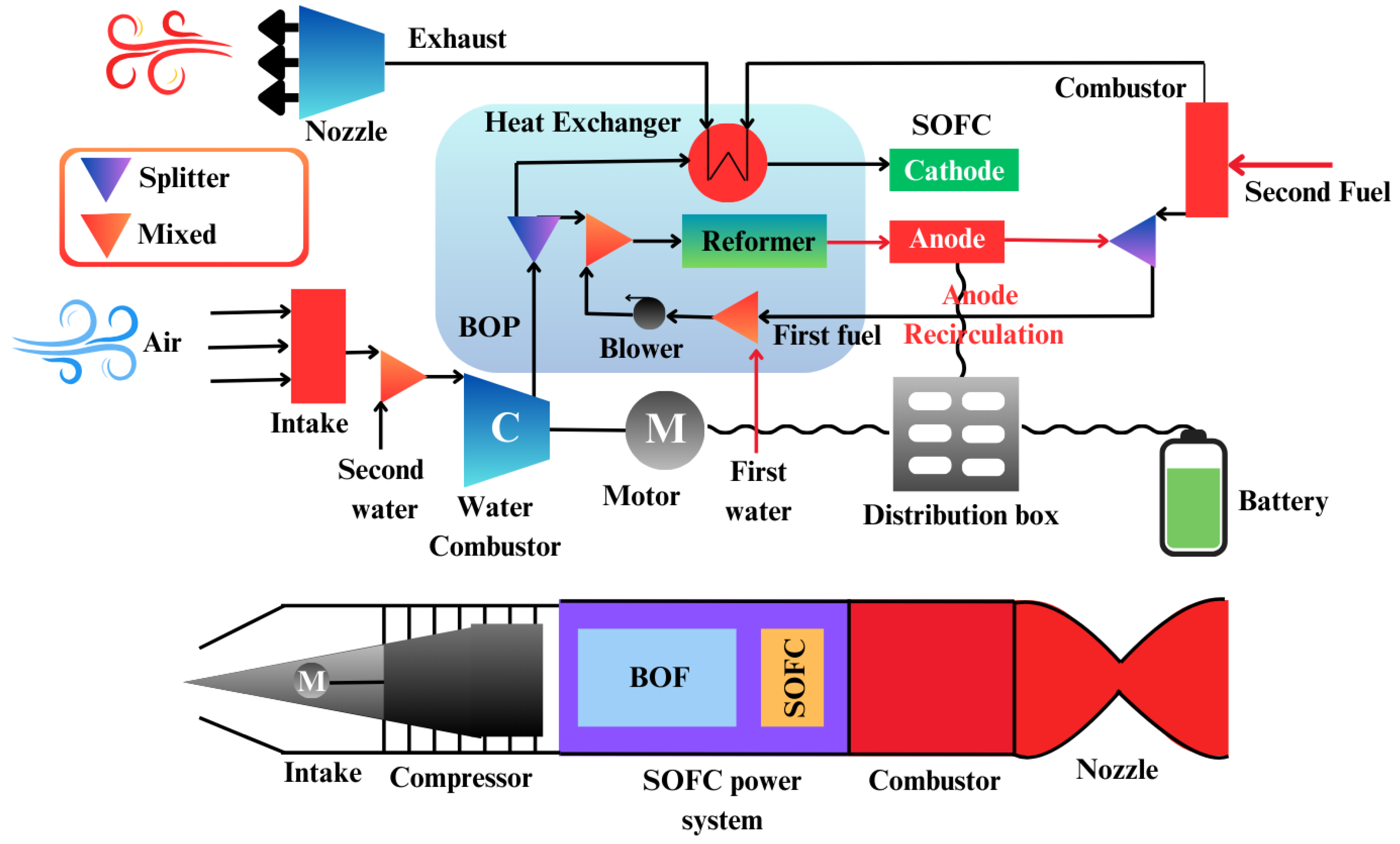
Fuel cells hold a significant advantage over traditional battery systems in terms of weight-to-energy ratio, allowing for decreased heat loss and more efficient static operation. While battery-powered UAVs have an endurance limit of about one hour, fuel cell-powered UAVs have significantly greater mission durations due to high energy density and lightweight construction. Compared to combustion engines, these fuel cells integrated into UAVs are easier to maintain and more efficient for small systems, particularly unmanned aerial vehicles where traditional engines are less optimal. For these reasons, fuel cells are perfect for smaller UAVs. Dicks (2012) claims that roughly twenty unmanned aerial vehicles powered by fuel cells have been developed to this point.
A comparative study by Bradley et al. (2009) evaluated various propulsion systems for small-scale UAVs and concluded that a PEMFC system using compressed gaseous hydrogen offered the best potential for both range and endurance. In comparison, other propulsion systems considered included small internal combustion engines, lithium polymer batteries, zinc-air batteries, and propane-based SOFCs.
One innovative development in UAV design is the hybrid fuel cell/battery system, which incorporates onboard hydrogen production. For example, Kim et al. (2011) demonstrated a sodium borohydride-based system that showed superior efficiency in long-endurance flights compared to traditional battery-powered and combustion-based UAVs. For extended high-altitude flights, NASA’s Helios UAV utilized a hybrid propulsion system that combined solar cells, a regenerative fuel cell, and backup batteries. While fuel cells currently cannot meet the high energy and power density requirements of manned military or commercial aircraft, several small-scale manned aircraft experiments have explored the use of hybrid hydrogen PEMFC systems.
Fuel cells have also found applications in high-altitude balloons, with NASA utilizing AFCs and PEMFCs in space missions for decades, particularly in manned space programs. The water produced as a byproduct of these fuel cells provides an additional advantage, as it can be utilized for drinking water and other mission-critical needs. With growing interest in space exploration, fuel cells are again being considered for future space missions, offering the potential for sustainable energy production in the challenging conditions of space (Burke, 2003).
6.1.2. Marine Propulsion
The adoption of fuel cells in the marine sector is rapidly expanding, particularly in auxiliary power units (APUs) on yachts and boats. However, the application of fuel cells for marine propulsion is poised to extend beyond recreational vessels to include cargo ships, ferries, submarines, and various other watercraft. Fuel cells offer several advantages, including efficient static operation, high energy conversion efficiency, and low emissions. Despite these benefits, challenges related to longevity, shock resistance, and the ability to withstand salt air remain obstacles to widespread adoption.
Presently, the marine fuel cell industry is concentrating on three prime technologies: Proton Exchange Membrane Fuel Cells (PEMFCs), Solid Oxide Fuel Cells (SOFCs), and Molten Carbonate Fuel Cells (MCFCs). Perhaps the most significant event in this industry was the first yacht demonstration in Germany in 2003, equipped with a hybrid PEM fuel cell/lead-gel battery system for propulsion, which also served as an auxiliary power source. This milestone was followed by the 2008 debut of the first commercial passenger ship equipped with a hybrid PEM fuel cell/lead-gel battery propulsion system, which was noted for its astonishing doubling of efficiency relative to traditional diesel ships. In 2009, Austria showcased an autonomous hydrogen fuel cell boat that ran on hydrogen created by solar energy and managed to travel longer distances compared to typical battery-operated boats. That was followed by Germany's introduction of the first hydrogen fuel cell-operated ferry in 2011 (Sharaf & Orhan, 2014).
The issue of hydrogen’s low volumetric density has been partially addressed by proposals such as those by Alkaner et al. (2006), who suggested onboard reformation of traditional marine fuels for hydrogen production, making fuel cells a viable option for commercial ships.
As seen in Figure 25, which illustrates the proposed system layout of a Solid Oxide Fuel Cell (SOFC) integrated with an internal combustion engine (ICE) for maritime applications, exergy efficiencies in marine fuel cell systems have been found to be comparable to those of other power arrangements. The system layout incorporates key components such as the preheater (P.H.), cooler (C.O.), superheater (S.H.), evaporator (Evap), and economizer (Eco), all contributing to optimizing performance in marine contexts.
Successful deployments of oxygen/hydrogen fuel cell-powered submarines have demonstrated significant benefits, including enhanced underwater endurance, high efficiency, reduced heat and magnetic signatures, and lower noise levels. These attributes make fuel cell-powered submarines ideal candidates for modern military operations, where undetectability is crucial. As a result, several naval forces—particularly the Italian, Greek, and South Korean fleets—have shown considerable interest in investing in these innovative vessels (Sharaf & Orhan, 2014).
6.1.3. Auxiliary Power Units (APUs)
An Auxiliary Power Unit (APU) generates non-propulsive power for a vehicle, serving a crucial role in providing energy for various onboard systems. Unlike portable generators commonly used in boats and recreational vehicles (RVs), APUs are integrated directly into the vehicle. These units are especially important for large commercial airplanes, where power demands can reach up to 500 kW, requiring a wide range of operational capacity (Sharaf & Orhan, 2014). By decoupling the APU from the primary propulsion system, vehicles can optimize their overall energy efficiency. This strategy is widely adopted across various modes of transport, including cars, boats, ships, locomotives, airplanes, buses, military vehicles, and more.
APUs are responsible for powering a variety of vehicle functions, such as electrical appliances, air conditioning, refrigeration, entertainment systems, lighting, heating, and communications. Given their significant electrical energy demands, certain vehicles like recreational boats, airplanes, large trucks, service vehicles, and law enforcement vehicles present particularly promising markets for APUs. Furthermore, refrigeration vehicles also require reliable auxiliary power systems to maintain temperature control.
The demand for APUs is expected to rise as automobiles incorporate more electrical appliances and comfort features. While APUs are widely used, fuel cells present a cleaner alternative, offering shorter startup times, reduced noise, fewer pollutants, and higher efficiency. For example, Figure 26 illustrates the integration of Solid Oxide Fuel Cells (SOFCs) into hybrid APU systems for internal combustion engine (ICE) hybrid systems. These hybrid systems can significantly improve vehicle efficiency while reducing environmental impact.
Studies have shown that using fuel cell APUs in heavy-duty trucks, in place of traditional APUs, can lead to substantial reductions in emissions. It is possible to decrease particulate matter-10 emissions by as much as 65%, NOx emissions by up to 95%, and CO2 emissions by over 60% (Henne & Friedrich, 2009). Heavy-duty trucks, which often operate at idle for extended periods, waste fuel, increase pollutant emissions, and suffer from inefficient engineering. The development of fuel cells for APU applications, including Proton Exchange Membrane Fuel Cells (PEMFCs), Direct Methanol Fuel Cells (DMFCs), and SOFCs, is gaining momentum. These fuel cells can operate on a variety of fuels such as hydrogen, petrol, natural gas, LPG, methanol, and diesel.
6.1.4. Light Traction Vehicles (LTVs)
Light traction vehicles (LTVs) encompass a variety of transportation and material-handling machines, including personal wheelchairs, golf carts, motorbikes, electric-assisted bicycles, airport tugs, and various types of equipment such as pallet trucks, forklifts, and tow trucks. These vehicles, particularly forklifts, have gained notable attention for showcasing the application of fuel cell technology in the transportation sector. In North America alone, approximately 2.5 million forklifts and similar material-handling vehicles play a crucial role in the warehouse and distribution industries (Qi, 2009).
Historically, these vehicles have been powered by combustion engines fueled by diesel, petrol, LPG, compressed natural gas, or propane, along with rechargeable lead-acid batteries. However, the adoption of fuel cells is increasingly gaining traction due to their numerous benefits. These advantages include extended operational hours (ranging from 2 to 5 minutes), adaptability to temperature fluctuations, minimal self-degradation during charge/discharge cycles, and the ability to operate both indoors and outdoors. Moreover, fuel cells offer space-efficient refueling stations, lower harmful emissions, high efficiency, exceptional load-following dynamics, and reduced maintenance needs. With these qualities, fuel cells have the potential to revolutionize traditional forklifts and similar vehicles over time.
While onboard hydrogen generation systems remain less feasible for this purpose, refueling stations utilizing liquid hydrogen or fuel-feeding systems are becoming more viable alternatives. Currently, the U.S. market has around 1,300 fuel cell-powered forklifts, which are typically integrated with ultracapacitors for quick power delivery and 5-20 kW Proton Exchange Membrane Fuel Cells (PEMFCs) (Dicks, 2012).
Additionally, fuel cell-powered electric-assisted bicycles and scooters are in development, offering an environmentally friendly alternative for short to medium-distance travel. These vehicles present a promising solution to reducing traffic congestion while avoiding the use of expensive hydrocarbon fuels (Hwang, 2012). The success of fuel cell-powered personal wheelchairs and light carts further highlights the expanding potential of LTVs across various sectors (Sharaf & Orhan, 2014).
6.1.5. Heavy-Duty Fuel Cell Electric Vehicles (H-FCEVs)
As the transportation sector continues to explore environmentally sustainable solutions, Heavy-duty Fuel Cell Electric Vehicles (H-FCEVs) have emerged as a promising option. These vehicles, which include buses, heavy-duty trucks, locomotives, vans, and utility trucks, utilize fuel cells for electric power, offering several advantages over conventional diesel-powered alternatives.
One prominent example of an H-FCEV is the XCIENT Fuel Cell Truck, developed by Hyundai. Figure 27 illustrates this state-of-the-art heavy-duty truck, which is powered by hydrogen fuel cells. The XCIENT Fuel Cell Truck from Hyundai is an example of a product which illustrates prospect of fuel cell technology in the heavy-duty vehicle segment. FCEBs are regarded as cleaner options for public transport because the buses are less noisy, less polluting, and have lower emissions compared to other vehicles, like traditional diesel ones (Hyundai, 2021).
The FCEB’s benefits, such as noiseless operation and lower emission, are especially important for environmentally sensitive urban areas. Because of their fixed routes and the possibility to accommodate design flexibility, buses are good candidates for hydrogen fuel cell technology which offers better hydrogen storage and transport infrastructure. Initiatives to promote the adoption of FCEBs for public transportation have been launched by governments and the private sector in many parts of the world for example Australia, Europe, Canada, China, Brazil, and the United States (Saxe et al., 2008). Theses projects are geared towards the development of public transport systems that are sustainable and friendly to the environment, which objectives are in harmony with global targets.
FCEBs, on the other hand, have issues with economic efficiency when compared to conventional diesel powered buses. The primary barrier is the lack of development of fuel cell technology and the absence of economies of scale which make these vehicles costlier. Nevertheless, achievement, especially in the aspects of durability and cost-efficiency, has been noted due to developers like Ballard, Hydrogenics, and Daimler AG (Sharaf & Orhan, 2014). The improvements are vital in ensuring that fuel cell buses can be produced at affordable prices.
Other industries are also progressing in developing H-FCEVs. For instance, Vision has developed a hydrogen fuel cell class 8 truck which works at different ambient temperatures and possesses high power, good range, and fast refueling capabilities. In addition, Heliocentris in Germany has been building a fuel cell hybrid refuse collection vehicle which uses diesel engines in addition to fuel cells, demonstrating the adaptability of fuel cell technology. Interest in the implementation of fuel cells in locomotives has also been growing, with some investigations suggesting good efficiency and dependable power output (Sharaf & Orhan, 2014).
6.1.6. Light-Duty Fuel Cell Electric Vehicles (L-FCEVs)
Light-duty fuel cell electric vehicles (L-FCEVs) offer several significant advantages over traditional internal combustion engine vehicles. These benefits include quieter operation, enhanced energy efficiency, reduced greenhouse gas emissions, and greater flexibility in design. As depicted in Figure 28, which provides an overview of the hydrogen-powered drivetrain in Fuel Cell Electric Vehicles (FCEVs), the system operates with key components that contribute to its environmentally friendly performance. Hydrogen is stored in high-pressure tanks, which are then supplied into the fuel cell stack. Inside the fuel cell, hydrogen combusts with oxygen to produce electricity. The fuel cell boost converter raises the voltage level, and the electricity is employed by the power control unit. The vehicle is then powered by a motor, and the additional energy depleted from the battery will be supplied when needed. Importantly, water vapor (H2O) emission is the only byproduct released from this process, showcasing the environmentally friendly benefit of FCEVs. Unlike other vehicles, L-FCEVs L-FCEVs have higher efficiency during cold weather and longer driving range compared to light-duty battery electric vehicles (L-BEVs), and faster re-fueling usually takes less than two minutes. Moreover, their weight is comparatively lower than battery-powered ones. However, due to the challenges surrounding stack durability and lifecycle costs, L-FCEVs still has limited commercial availability. Various technical difficulties still need to be solved like system size and mass optimization, cold weather start-heating, air compression system enhancement, heat dissipation improvement, catalyst tolerance increase, and membrane humidification, start-stop cycle endurance, and hydrogen safety issues. Furthermore, compliance with hydrogen storage regulations poses additional challenges. L-FCEVs predominantly utilize proton exchange membrane fuel cells (PEMFCs), a technology that is being increasingly adopted by leading automakers such as Nissan, Hyundai, Daimler AG, Volvo, Volkswagen, Honda, and General Motors. A notable milestone was achieved when Hyundai’s L-FCEV, the ix35, entered mass production in 2013, with plans for deployment in Europe ("First Hyundai Ix35 FCEV Rolls off Assembly Line in Korea," 2013). The competition between L-FCEVs and L-BEVs primarily centers around the choice of energy source, energy conversion chain, and design specifications. Until one of these technologies proves superior, light-duty hybrid electric vehicles (L-HEVs) that combine fuel cells and batteries may serve as a transitional solution. In terms of driving range, simulations by Thomas (2009) show that L-FCEVs can achieve ranges greater than 160 km when using natural gas or biomass as the primary energy source. The study considers critical parameters such as vehicle mass, storage space, cost, emissions, refueling time, and energy efficiency. For L-FCEVs, hydrogen is generally produced off-board and supplied through designated fueling stations. Ongoing research is investigating alternative storage methods to improve the long-term viability of L-FCEVs. While current hydrogen storage techniques have limitations, technologies such as cryo-compressed hydrogen storage, ammonia borane chemical storage, and alkane metal hydrides show promise (Sharaf & Orhan, 2014). Onboard hydrogen generation, while not feasible at present due to constraints in size, weight, startup time, and safety, could potentially become viable with future advancements in reformation and hydrogen generation technologies.
6.2. Stationary Applications
Power generation for home, commercial, and industrial uses heavily rely on stationary fuel cells. They meet the needs for grid-assisted and grid-independent power supplies. These include Remote-area power supplies (RAPS), emergency backup power supplies (EPS), and combined heat and power (CHP) generation. Almost 70% of yearly fuel cell shipments at the MW level are accounted for by the stationary fuel cell sector 24.
6.2.1. Remote-Area Power Supply (RAPS)
Figure 28 illustrates the schematic of a simulated solar-hydrogen-fuel cell system designed for a Remote-Area Power Supply (RAPS) application, offering a clear visualization of how renewable energy sources, like solar power, can be combined with hydrogen and fuel cells to provide a reliable electricity solution for off-grid areas. This system is especially important for providing electricity in remote locations that lack access to the main power grid.
Fuel cells are crucial for powering isolated areas, where conventional grid infrastructure is not available. RAPS systems present a cost-effective solution for electrifying rural and urban off-grid zones, particularly in challenging terrains such as forests and mountainous regions, where extending traditional power lines is impractical or too expensive. The cost of extending the grid is high due to issues such as significant transmission losses, low population density, and the need for extensive infrastructure. In these regions, RAPS technologies hold great promise, especially in developing countries.
Currently, a combination of hydrocarbon-based, renewable-based, or hybrid systems are used in RAPS solutions (Sharaf & Orhan, 2014). An important aspect of RAPS development is the use of Combined Heat and Power (CHP) systems, which improve performance by generating additional power, particularly in urban off-grid areas. While diesel engines have traditionally been used for RAPS, they are becoming less favorable due to their high carbon emissions and noise pollution. Fuel cells offer a cleaner alternative, as they can utilize light hydrocarbon reforming or natural gas. However, the challenge of transporting these fuels to remote areas remains a significant hurdle.
To offer a more sustainable and independent energy solution, hybrid and integrated energy systems are being explored. These systems combine renewable energy sources, such as solar photovoltaics (PV), with energy storage technologies like batteries, to provide reliable power. In fact, PV-based RAPS systems are expected to generate up to 130 GW by 2030, serving residential, commercial, and industrial users (Perrin & Lemaire-Potteau, 2009).
One of the main challenges with renewable energy is its intermittency, which can be effectively addressed by integrating hydrogen systems. As depicted in Figure 28, these systems typically include a water electrolyzer, fuel cells, and hydrogen storage, creating a more dependable and sustainable energy system. Despite the advantages of hydrogen systems, they face competition from PV and battery-based systems, which are more commonly used in RAPS applications. Research has shown that while hydrogen systems hold promise, they are not yet as cost-effective as conventional batteries. To become more competitive, the cost of fuel cell systems needs to be reduced by approximately €300/kW, while hydrogen storage tanks and water electrolyzers should see a 40% and 50% cost reduction, respectively (Sharaf & Orhan, 2014).
If the cost, efficiency, and durability challenges can be overcome, hydrogen fuel cell systems could provide a critical solution for the nearly two billion people worldwide who lack access to reliable grid electricity.
6.2.2. Emergency Backup Power Supply (EPS)
In the telecom industry, fuel cells are gaining traction as a critical alternative to traditional batteries in the emergency backup power supply (EPS) market. The growing popularity of fuel cells can be attributed to their exceptional power densities, high energy output, adaptability to diverse environments, compact size, long operational lifetimes (typically two to ten times longer than conventional lead-acid batteries), and modular design. These characteristics make them an ideal solution for industries that require reliable backup power, such as telecommunications, hospitals, data centers, banks, and government institutions. Among the various fuel cell technologies, Proton Exchange Membrane Fuel Cells (PEMFCs) and Direct Methanol Fuel Cells (DMFCs) are particularly favored in EPS applications, given their efficiency and performance (Varkaraki et al., 2003). High dependability is paramount in these sectors, where continuous, reliable power is necessary, particularly when grid electricity is unavailable. EPS systems typically need to provide power in the range of 2 to 8 kW to ensure smooth operations during power outages. The long-lasting nature of fuel cells makes them an attractive choice in this context, where uptime is critical. As shown in Figure 29, the integration of fuel cells into emergency power supply systems offers a promising solution, providing a reliable, sustainable energy source when conventional power fails (Varkaraki et al., 2022).
6.2.3. Combined Heat and Power (CHP) Generation
Decentralized, distributed power generation could be increasingly replaced by fuel cells due to their high efficiency, minimal emissions, excellent load-following capabilities, and stationary design. These advantages make fuel cells ideal for use in both large residential blocks and individual households for the distributed generation of Combined Heat and Power (CHP) or domestic electricity. In fact, Japan is a global leader in residential CHP fuel cell systems, with thousands of homes relying on them for both heating and electricity (Staffell et al., 2019). Fuel cell systems used for residential CHP can vary in size, offering capacities ranging from a few kilowatts to several megawatts to meet diverse load demands.
Figure 30 illustrates the schematic diagram for fuel cell micro-CHP systems, showcasing their typical configuration for residential applications (Hawkes et al., 2009).
To enhance their functionality, residential CHP fuel cells can be integrated into Combined Cooling, Heating, and Power (CCHP) systems. These systems not only provide electricity but also support space heating, household water heating, and cooling. The efficiency of CHP and CCHP systems can reach up to 80%, making them highly efficient energy solutions (Ma et al., 2011). However, further research is needed to address technical challenges and reduce capital costs associated with these systems. Larger residential complexes are generally more suited to high-temperature fuel cells (HTFCs), while Proton Exchange Membrane Fuel Cells (PEMFCs) and Phosphoric Acid Fuel Cells (PAFCs) are particularly appropriate for household-level CHP generation.
Designing CHP systems to either assist the grid or operate independently offers various operational options. Grid-independent systems face complexities due to dynamic load fluctuations, which can be mitigated by increasing the fuel cell capacity or integrating energy storage solutions, such as battery banks or ultracapacitors. In contrast, grid-assisted systems export excess power to the grid when demand is low and import electricity when load demands rise. Thermal energy storage is also critical for the effective operation of CHP systems. In terms of emissions, fuel cells powered by natural gas, such as Molten Carbonate Fuel Cells (MCFCs) and PAFCs, produce significantly fewer harmful pollutants (NOx, PM-10, and CO) compared to combustion-based distributed generation systems (M. Wang et al., 2010).
In addition to residential applications, the development of combined fuel cell cycles is being explored for use in industrial activities to simultaneously produce chemicals and energy. However, the primary technological challenge for stationary CHP fuel cells remains extending their lifespan to approximately 80,000 hours, a goal that is essential for their commercial viability (Sharaf & Orhan, 2014).
6.3. Portable Applications
There are two main markets for portable fuel cells:
6.3.1. Consumer Electronics
Research is underway to investigate the use of fuel cells in computers, cell phones, radios, camcorders, and other battery-powered gadgets. Typically, they provide 5 to 500 W power ranges, while some more sophisticated types can provide power up to the kW level (Sharaf & Orhan, 2014). Unlike stationary fuel cells, which are bulky and limited in their uses, portable fuel cells are lightweight and portable. They could be used in future personal devices as a result of their high energy density and adaptability, five to ten times higher than traditional rechargeable batteries. Because of its silent operation, energy density, low weight and high power in comparison to conventional battery-based equipment, portable fuel cells—specifically PEMFCs, direct methanol fuel cells (DMFCs) and reformed methanol fuel cells (RMFCs), —are also being used by the military industry.
6.3.2. Mobile and Emergency Power
These fuel cells are intended for individual usage during outdoor pursuits such as hiking and camping. They also supply emergency power for minor commercial uses like surveillance and transportable signs.
Even though portable fuel cells have benefits, including reduced weight, increased energy density, and no requirement for electrical recharging, they have not yet reached cost and durability goals. Toys, kits, gadgets, and miniature remote-control cars are among the rapidly expanding markets in the portable sector, as are portable battery chargers. Significant advancements in the mobile fuel cell industry depend on addressing several technical issues, including heat dissipation, noise reduction, emissions control, fuel storage and distribution, shock resilience, responsiveness to demand fluctuations, varied operating conditions, air pollution tolerance, and the capacity for fuel containers to be reused and recycled.
7. Major Challenges of Fuel Cell Technology
Fuel cell technology has the capability to address the current and future energy demands of the earth with a clean and efficient energy system. However, the current scenario in fuel cell technology consists of several challenges that need to be addressed for its widespread adoption. High manufacturing cost, durability and safety in transport are two of the most prominent concerns in employing fuel cell technologies on a commercial basis. As illustrated in Figure 31, these issues collectively shape the barriers to fuel cell deployment, with manufacturing costs remaining a primary obstacle. Moreover, enhancing the durability of fuel cells to withstand operational stress over time and ensuring the safety of fuel cell systems, especially in transport, are critical areas for ongoing research and development.
7.1. Cost
Primarily, Fuel cell technology is lagging the current energy technologies available in the market in terms of cost in manufacturing (J. Wang et al., 2018b). For example, fuel cell systems for automotive propulsion systems cost around 800% more than the usual internal combustion engines (Dubey et al., 2022). The current challenge in fuel cell application lies in developing cost-effective materials for membrane assemblies in the fuel cell. Membranes, catalysts, and diffusion layer account for approximately half of the cost associated with the fuel cell while Pt, used as the most common catalyst so far, contributes about a third of the overall stack expense. Current fuel cell research is motivated towards an affordable replacement of expensive Nafion membranes and Pt metal as a catalyst (Wilberforce et al., 2016).
7.2. Fuel Storage
The limitations of hydrogen fuel storage in fuel cells consist due to inadequate methods of purification, high-pressure requirements, and sensitivity to CO. Significant research is necessary for purification of hydrogen beyond existing technologies. PEMFCs require to eliminate CO to achieve pure hydrogen (Soltani & Benchouia, 2019). The special storage need of gaseous hydrogen requires up to 10,000 psi of pressure and liquid hydrogen is to be stockpiled at cryogenic temperatures as low as -253oC (Ahmed et al., 2023). Due to the risks in high pressure hydrogen storage, it has also been necessary to develop an economical storage technology to achieve higher density in storage (Liu, 2018). The constraint of energy storage size has also hindered the solutions to limited load following problem in fuel cells (Hu et al., 2019).
7.3. Safety
While fuel cells are relatively safer in terms of any potential explosion and related hazards, the fuel, hydrogen, may pose challenges to the safe operation of them. Catalyst degradation over the use and electrolytic poisoning are significant challenges of fuel cells which ultimately reduce the efficiency and performance of the fuel cell. (4) In addition, characteristically hydrogen is prone to leakage coupled with its low-energy ignition phenomenon increases the risk of explosion, if not properly managed (He, 2017). Future challenge lies in developing effective hydrogen sensors to sense and monitor in case of any leak (Foorginezhad et al., 2021).
7.4. Durability
The durability of a fuel cell largely relies on the mechanical resilience of the electrodes, which are susceptible to tensile load due to hygrothermal buckling of membrane resulting in mechanical damage (Pyo, 2022). Other factors that require attention for the durability of fuel cells include electrochemical and fluidic instabilities, fuel stack voltage range, support corrosion, various physical and chemical interactions among components and electrolytes. [all except 1] Increase in durability can help abating the cost and increasing commercialization and industrial utilization of fuel cells. An efficient ‘Fuel Cell Management System’ needs further development and research (Dubey et al., 2022). Further research is also necessary in studying nanostructure modifications to achieve desired mechanical properties (J. Wang et al., 2018b).
7.5. Energy-Intensive Hydrogen Production
To date, hydrogen production is largely dependent on fossil fuels. Reshaping hydrogen production procedure to renewable sources still is a matter of concern regarding cost and efficiency (Garland et al., 2012). Hydrogen generation with fossil fuels is obviously energy-intensive and produces a large carbon impact., impeding the transition to clean energy source. Moreover, hydrogen production becomes expensive and complex if it employs CCS (carbon capture and storage) system to reduce CO2 emission from fossil fuel use (Sazali, 2020). To implement a sustainable and green hydrogen economy, it has become imperative to use sustainable energy sources for the fabrication of hydrogen.
8. Future Prospects of Fuel Cell as Energy Storage System
There are ample opportunities for fuel cells as an energy storage system as it can efficiently convert chemical energy into electricity. Fuel cell system’s designs and materials require further study to make it a cost-effective and more efficient option than internal combustion engines for industrial use. Unlike other power devices, fuel cells are not constrained by Carnot principles which make them a viable alternative for future energy storage systems (Wilberforce et al., 2016). For future energy storage solutions Solid Oxide Fuel Cells (SOFCs) and Proton exchange membrane fuel cells (PEMFCs) are most prospective as well as competitive.
It has been pivotal to recycle Pt electrocatalysts after their life span and at the same time reduce excessive loading of them. Possible research trends can be motivated to find nanostructured oxides and carbides which show high conductivity and can support catalysts for PEMFCs. Though there are significant efforts in developing electrocatalysts for PEMFCs which do not derive from precious metals such as Pt, they usually perform suitably for anion-exchange-membrane fuel cells (AEMFCs). High temperature PEMFCs offer alternative fuel options as hydrogen carrier. To reduce the related cost of hydrogen infrastructure, the high energy density of methanol makes it a potential substitute source of hydrogen and reforming temperature of 240-260oC. Methanol Steam Reformers (MSRs) with FCs can be useful in applications for unmanned aerial vehicles and man-portable power which find bulky hydrogen storage tanks as an impractical solution. Also, HT-PEMFCs can be instrumental in developing Direct Alcohol Fuel Cells (DAFCs). Further research can be motivated in introducing various hybrid membranes to accelerate the development of HT-PEMFCs.
On the other hand, SOFCs have got attention due to their anti-corrosion characteristics and no requirement of precious metal electrocatalysts. It also can use a wide array of fuels, especially alcohol-based liquids. SOFCs have scope of further improvement in activity and stability of electrode materials as the durability of fuel cell depends highly on them. Advanced SOFCs use Ni–YSZ cermet anodes, Y2O3–ZrO2 (YSZ) electrolytes and (La,Sr)MnO3-based perovskite cathodes. Ongoing developments in SOFCs include the impact of polarization-induced interface on stability and microstructure. Another research development is to obtain Intermediate-Temperature SOFCs (IT-SOFCs), at 500-600oC) along with its benefits of lower cost and higher thermal stability. It requires nanostructured electrode development to address the associated challenges of reduced ionic conductivity and high loss in polarization.
In addition, research in coming days can also emphasize finding more suitable electrolytes. Considering the cost, scarcity and applicability, non-metal catalysts can change the landscape of fuel cell applications. Doped ceria and bismuth are promising electrolyte options but require improvement in the case of thermal and chemical stability, ionic conductivity for commercial use. (He, 2017)
For vehicle operations, fuel cells are an option for future energy storage systems. Though fuel cells have lower energy density than the conventional battery, their environmental benefits and virtually negligible greenhouse emission outweigh the disadvantages. However, emission of particulate matters needs to be controlled by employing filters. For future use in vehicles, Proton-Exchange Membrane Fuel Cells (PEMFCs) are usually preferable ascribed to their larger energy density, desired weight and size and less chance of corrosion. But their benefits are overshadowed by their high cost, thus, interrupting large-scale production of hydrogen fuel-based vehicles. To avail the opportunity of using ethanol as fuel, Nissan is working in Solid Oxide Fuel Cells to be competitive with other EVs (Hu et al., 2019).
Fuel cells can be used in both mobile and stationary applications. Fuel cell applications for residential and industrial energy storage systems can be promising for dependable and eco-friendly source of power. It can be also considered as auxiliary and backup power source for telecommunication companies, installed in remote areas. (J. Wang et al., 2018a)
9. Conclusion
This comprehensive review analyzes Fuel Cell (FC) technologies, exploring their application metrics to compare technical details and future development prospects for stationary purposes. We can distinguish between low-temperature systems by examining various FC types, including hydrogen, Polymeric Electrolyte Membrane, alkaline, phosphoric acid, direct methanol, molten carbonate, and solid oxide FCs.
The paper offers an in-depth evaluation of characteristics using economic criterions such as efficiency, operating temperature, power levels and specific energy, energy density and cost metrics, as well as lifespan. Notably, proton exchange membrane FCs outperform systems in terms of power. Additionally, solid oxide FCs demonstrate efficiency levels ranging from 50% to 70% higher than direct methanol FCs, which operate at around 35%.
A comparative analysis of energy level cost factors (including power cost), power density, and energy density across FC types highlights their unique features and trade-offs. While proton exchange membrane FCs may have a power cost of up to $10,200/kW compared to other types, the diverse range of costs and efficiency metrics observed among the different FC types indicate their suitability for various applications and commercial readiness.
This study highlights the level of advancement in fuel cells, predicting when they will become available for use. It is important to highlight that phosphoric acid fuel cells are considered the generation that is already prepared for commercialization. Conversely, though, solid oxide fuel cells are classified as third-generation systems. They are expected to be further developed and ready for commercial use within 5 to 10 years.
Regarding the upcoming five to ten years, there are both prospects and challenges when it comes to integrating fuel cells (FCs) into electrical power systems. To ensure market penetration of FCs, it is crucial to focus on cost-effectiveness, longevity, simplified operations, and safety considerations. This entails handling intricate fuel processing and system functioning issues as well as assuring user safety with regard to hydrogen volatility.
One area that requires intensified research attention is the application of FCs in microgrid systems. These systems have the potential to provide continuous power sources, which can significantly benefit existing power grids and help alleviate energy scarcity in regions. Further investigation into FC technologies is necessary to enhance the energy generation of microgrid systems.
In summary, this review highlights FC technologies' nature and ability to reshape energy landscapes. Continuous development and study are important in optimizing the performance, cost efficiency, and safety of FCs for adoption across various applications – including microgrid systems.
Abbreviations
°C – Celsius
AEMFCs – Anion-Exchange-Membrane Fuel Cells
AFC – Alkaline Fuel Cell
AMFC – Alkaline Membrane Fuel Cell
ANN – Artificial Neural Network
APU – Auxiliary Power Unit
BES – Battery Energy Storage
BES – Battery Energy Storage
BT – Battery
CAES – Compressed Air Energy Storage
CCHP – Combined Cooling, Heating, and Power
CCP – Combined Cooling and Power
CH4 – Methane
CHP – Combined Heat and Power
CO – Carbon Monoxide
CO2 – Carbon Dioxide
COE – Cost of Energy
CsH2PO4 – Cesium Dihydrogen Phosphate (solid acid proton conductor)
CsHSO4 – Cesium Hydrogen Sulfate (solid acid)
DAFCs – Direct Alcohol Fuel Cells
DCFC – Direct Carbon Fuel Cell
DC-MCFC – Direct Carbon Molten Carbonate Fuel Cell
DC-SOFC – Direct Carbon Solid Oxide Fuel Cell
DG – Diesel Generator
DMFC – Direct Methanol Fuel Cell
EPS – Emergency Backup Power Supply
ER – External Reforming
ESS – Energy Storage System
EVs – Electric Vehicles
FC – Fuel Cell
FCEBs – Fuel Cell Electric Buses
FCEV – Fuel Cell Electric Vehicle
FES – Flywheel Energy Storage
FES – Fuel Energy Storage
FIB-SEM – Focused Ion Beam Scanning Electron Microscopy
GCS – Grid-Connected Systems
GES – Gravity Energy Storage
GW – Gigawatt
H2 – Hydrogen
H2O – Water
H2SO4 – Sulfuric Acid
H3PO4 – Phosphoric Acid
HCl – Hydrochloric Acid
H-FCEV – Heavy-Duty Fuel Cell Electric Vehicle
HNO3 – Nitric Acid
HOR – Hydrogen Oxidation Reaction
HTFCs – High-Temperature Fuel Cells
ICE – Internal Combustion Engine
i-Power Density – Current-Power Density (curves)
IR – Internal Reforming
IT-SOFCs – Intermediate-Temperature Solid Oxide Fuel Cells
i-V – Current-Voltage (curves)
K – Kelvin
KOH – Potassium Hydroxide
kW – Kilowatt
kWh – Kilowatt-hour
La,Sr – Lanthanum Strontium
L-BEVs – Light-duty Battery Electric Vehicles
L-FCEVs – Light-duty Fuel Cell Electric Vehicles
L-HEVs – Light-duty Hybrid Electric Vehicles
LHS – Latent Heat Storage
Li – Lithium (batteries)
LSC – La₀.₆Sr₀.4CoO3
LTV – Light Traction Vehicle
MATLAB/Simulink – MATLAB and Simulink (simulation tools)
MCFC – Molten Carbonate Fuel Cell
MOFs – Metal–Organic Frameworks
MPa – Megapascal
MSRs – Methanol Steam Reformers
MW – Megawatt
MWh – Megawatt-hour
NaS – Sodium-Sulfur (batteries)
NiCd – Nickel-Cadmium (batteries)
Ni–YSZ – Nickel–Yttria-Stabilized Zirconia
NPC – Net Present Cost
O2 – Oxygen
OCV – Open-Circuit Voltage
ORR – Oxygen Reduction Reaction
PAFCs – Phosphoric Acid Fuel Cells
PCM – Phase Change Materials
PEFC – Polymer Electrolyte Fuel Cell
PEM – Polymer Electrolyte Membrane
PEMFC – Proton Exchange Membrane Fuel Cell
PHES – Pumped Hydro Energy Storage
Pt/C – Platinum/Carbon (cathode material)
PTES – Pumped Thermal Energy Storage
PtRu/C – Platinum Ruthenium/Carbon (anode material)
PV – Photovoltaic
RAPS – Remote-Area Power Supply
RE – Renewable Energy
RES – Renewable Energy Systems
SHS – Sensible Heat Storage
SMES – Superconducting Magnetic Energy Storage
SOFCs – Solid Oxide Fuel Cells
T – Temperature
TCES – Thermochemical Energy Storage
U.S. – United States
UAV – Unmanned Aerial Vehicle
V-I – Voltage-Current
W – Watt
YSZ – Yttria-stabilized Zirconia
References
- Afroze, S. , Reza, M. S., Somalu, M. R., & Azad, A. K. (2023). Super–protonic conductors for solid acid fuel cells (SAFCs): a review. Eurasian Journal of Physics and Functional Materials. [CrossRef]
- Agrawal, S. , Chorsiya, S., & Palwalia, D. K. (2018). Hybrid energy management system design with renewable energy sources (fuel cells, PV cells and wind energy): a review. IJSET.
- Ahmed, H. , Adebayo, P., Ahmed, M., & Arbab, A. I. (2023). Hydrogen Fuel Cell Technology: Benefits, Challenges, and Future Potential. Journal of Energy Technologies and Policy. [CrossRef]
- Ahn, C.-Y. , Ahn, J., Kang, S. Y., Kim, O.-H., Lee, D. W., Lee, J. H., Shim, J. G., Lee, C. H., Cho, Y.-H., & Sung, Y.-E. (2020). Enhancement of service life of polymer electrolyte fuel cells through application of nanodispersed ionomer. Science Advances. [CrossRef]
- Ait Hammou Taleb, S. , Brown, D., Dillet, J., Guillemet, P., Mainka, J., Crosnier, O., Douard, C., Athouël, L., Brousse, T., & Lottin, O. (2018). Direct Hybridization of Polymer Exchange Membrane Surface Fuel Cell with Small Aqueous Supercapacitors. ( 18(3), 299–305. [CrossRef]
- Al-Sharafi, A. , Sahin, A. Z., Ayar, T., & Yilbas, B. S. (2017). Techno-economic analysis and optimization of solar and wind energy systems for power generation and hydrogen production in Saudi Arabia. Renewable and Sustainable Energy Reviews. [CrossRef]
- Arani, A. A. K. , Karami, H., Gharehpetian, G. B., & Hejazi, M. S. A. (2017). Review of Flywheel Energy Storage Systems structures and applications in power systems and microgrids. Renewable and Sustainable Energy Reviews. [CrossRef]
- Asghari, M. , & Brouwer, J. (2019). Integration of a Solid Oxide Fuel Cell with an Organic Rankine Cycle and Absorption Chiller for Dynamic Generation of Power and Cooling for a Residential Application. ( 19(4), 361–373. [CrossRef]
- Baldi, F. , Wang, L., Pérez-Fortes, M., & Maréchal, F. (2019). A Cogeneration System Based on Solid Oxide and Proton Exchange Membrane Fuel Cells With Hybrid Storage for Off-Grid Applications. In Frontiers in Energy Research (Vol. 6).
- Barakat, M. , Tala-Ighil, B., Chaoui, H., Gualous, H., & Hissel, D. (2020). Energy Management of a Hybrid Tidal Turbine-Hydrogen Micro-Grid: Losses Minimization Strategy. Fuel Cells. [CrossRef]
- Berg, P. , & Findlay, J. (2009). Mass Transport Phenomena in a MCFC Cathode, 0909. [Google Scholar]
- Brushett, F. R. , Naughton, M. S., Ng, J. W. D., Yin, L., & Kenis, P. J. A. (2012). Analysis of Pt/C electrode performance in a flowing-electrolyte alkaline fuel cell. International Journal of Hydrogen Energy, 2570. [Google Scholar] [CrossRef]
- Bukar, A. L. , Modu, B., Gwoma, Z. M., Mustapha, M., Buji, A. B., Lawan, M. B., Tijjani, I., Benisheik, U. A., Bukar, A., & Mai, K. B. (2017). Economic assessment of a pv/diesel/battery hybrid energy system for a non-electrified remote village in Nigeria. European Journal of Engineering and Technology Research.
- Campanari, S. , Gazzani, M., & Romano, M. C. (2013). Analysis of Direct Carbon Fuel Cell Based Coal Fired Power Cycles With CO2 Capture. Journal of Engineering for Gas Turbines and Power. [CrossRef]
- Cao, D. , Sun, Y., & Wang, G. (2007). Direct carbon fuel cell: Fundamentals and recent developments. Journal of Power Sources. [CrossRef]
- Chang, H. , Xu, X., Shen, J., Shu, S., & Tu, Z. (2019). Performance analysis of a micro-combined heating and power system with PEM fuel cell as a prime mover for a typical household in North China. International Journal of Hydrogen Energy, 4965. [Google Scholar] [CrossRef]
- Chen, J. J. , Gao, X. H., Yan, L. F., & Xu, D. G. (2015). Progress and Challenges in the Direct Carbon Fuel Cell Technology. G. ( 49, 109–129. [CrossRef]
- Chen, K. (2022). Types, applications and future developments of gravity energy storage. Highlights in Science, Engineering and Technology. [CrossRef]
- Contreras, R. R. , Almarza, J., & Rincón, L. (2021). Molten carbonate fuel cells: a technological perspective and review. Energy Sources, Part A: Recovery, Utilization, and Environmental Effects. [CrossRef]
- Corigliano, O. , Pagnotta, L., & Fragiacomo, P. (2022). On the Technology of Solid Oxide Fuel Cell (SOFC) Energy Systems for Stationary Power Generation: A Review. Sustainability, 5276. [Google Scholar] [CrossRef]
- Cozzolino, R. , Tribioli, L., & Bella, G. (2016). Power management of a hybrid renewable system for artificial islands: A case study. Energy. [CrossRef]
- Cr-, N. , Stickles, R. P., Breuer, C. T., & Little, A. D. (1983). New Applications for Phosphoric Acid Fuel Cells.
- Cui, C. , Li, S., Gong, J., Wei, K., Hou, X., Jiang, C., Yao, Y., & Ma, J. (2021). Review of molten carbonate-based direct carbon fuel cells. Materials for Renewable and Sustainable Energy. [CrossRef]
- Desai, F. , Sunku Prasad, J., Muthukumar, P., & Rahman, M. M. (2021). Thermochemical energy storage system for cooling and process heating applications: A review. Energy Conversion and Management. [CrossRef]
- Desmaele, E. , Sator, N., Vuilleumier, R., & Guillot, B. (2019). Atomistic simulations of molten carbonates: Thermodynamic and transport properties of the Li 2 CO 3 - Na 2 CO 3 - K 2 CO 3 system. Journal of Chemical Physics. [CrossRef]
- Duan, Y. , Pang, Y., Liu, B., Wu, L., Hu, X., Li, Q., & Zhao, C. (2023). Synergistic Utilization of a CeO 2 -Anchored Bifunctionalized Metal–Organic Framework in a Polymer Nanocomposite toward Achieving High Power Density and Durability of PEMFC. ACS Sustainable Chemistry & Engineering, 5283. [Google Scholar] [CrossRef]
- Dubey, P. K. , Singh, B., & Kumar, V. (2022). 59 6037.
- Duman, A. C. , & Güler, Ö. (2018). Techno-economic analysis of off-grid PV/wind/fuel cell hybrid system combinations with a comparison of regularly and seasonally occupied households. Sustainable Cities and Society. [CrossRef]
- Eberle, U. , Felderhoff, M., & Schüth, F. (2009). Chemical and Physical Solutions for Hydrogen Storage. ( 48(36), 6608–6630. [CrossRef]
- Fendt, S. , Buttler, A., Gaderer, M., & Spliethoff, H. (2019). Comparison of Synthetic Natural Gas Production Pathways for the Storage of Renewable Energy. In Advances in Energy Systems (pp. 279–302). Wiley. [CrossRef]
- Ferguson, S. , & Tarrant, A. (2021). Molten Carbonate Fuel Cells for 90% Post Combustion CO2 Capture From a New Build CCGT. Frontiers in Energy Research. [CrossRef]
- Ferriday, T. B. , & Middleton, P. H. (2021). Alkaline fuel cell technology - A review. International Journal of Hydrogen Energy, 8489. [Google Scholar] [CrossRef]
- Foorginezhad, S. , Mohseni-Dargah, M., Falahati, Z., Abbassi, R., Razmjou, A., & Asadnia, M. (2021). Sensing advancement towards safety assessment of hydrogen fuel cell vehicles. Journal of Power Sources.
- Garland, N. L. , Papageorgopoulos, D. C., & Stanford, J. M. (2012). Hydrogen and fuel cell technology: Progress, challenges, and future directions. Energy Procedia. [CrossRef]
- Ghaebi, H. , & Soleymani, E. (2025). Investigating the effect of parameters in the thermodynamic analysis of the solid oxide fuel cell cycle using response surface methodology. ( 15(1), 181. [CrossRef] [PubMed]
- Ghenai, C. , & Bettayeb, M. (2019). Modelling and performance analysis of a stand-alone hybrid solar PV/Fuel Cell/Diesel Generator power system for university building. Energy. [CrossRef]
- Gökçek, M. , & Kale, C. (2018). Techno-economical evaluation of a hydrogen refuelling station powered by Wind-PV hybrid power system: A case study for İzmir-Çeşme. International Journal of Hydrogen Energy, 0615. [Google Scholar] [CrossRef]
- Guaitolini, S. V. M. , & Fardin, J. F. (2018). Fuel cells: History (short remind), principles of operation, main features, and applications. In Advances in Renewable Energies and Power Technologies (pp. 123–150). Elsevier.
- Halabi, L. M. , & Mekhilef, S. (2018). Flexible hybrid renewable energy system design for a typical remote village located in tropical climate. ( 177, 908–924. [CrossRef]
- Han, T. , Xie, Y., Li, L., Wu, Y., Yu, F., Wang, M., Zhang, J., Li, G., & Yang, N. (2024). Enhanced electrochemical performance of direct carbon solid oxide fuel cells by MgO-catalyzed carbon gasification: Experimental and DFT simulation studies. Ceramics International, 1644. [Google Scholar] [CrossRef]
- Han, Y. , Zhang, G., Li, Q., You, Z., Chen, W., & Liu, H. (2019). Hierarchical energy management for PV/hydrogen/battery island DC microgrid. International Journal of Hydrogen Energy, 5516. [Google Scholar] [CrossRef]
- Hawkes, A. , Staffell, I., Brett, D., & Brandon, N. (2009). Fuel cells for micro-combined heat and power generation. Energy & Environmental Science. [CrossRef]
- He, J. (2017). Safety Study Related to Hydrogen Leakage from Fuel Cell Systems.
- Herdem, M. S. , Mazzeo, D., Matera, N., Wen, J. Z., Nathwani, J., & Hong, Z. (2020). Simulation and modeling of a combined biomass gasification-solar photovoltaic hydrogen production system for methanol synthesis via carbon dioxide hydrogenation. Energy Conversion and Management. [CrossRef]
- Hu, X. , Li, P., Wang, K., Sun, Y., Zeng, D., Wang, X., & Guo, S. (2019). Joint Workload Scheduling and Energy Management for Green Data Centers Powered by Fuel Cells. ( 3(2), 397–406. [CrossRef]
- Hyundai. (2024). XCIENT Fuel Cell Truck | Hydrogen Truck | Hyundai Motor Company, /: Electrified Commercial Vehicles. https.
- Jayaprabakar, J. , Kumar, J. A., Parthipan, J., Karthikeyan, A., Anish, M., & Joy, N. (2023). Review on hybrid electro chemical energy storage techniques for electrical vehicles: Technical insights on design, performance, energy management, operating issues & challenges. Journal of Energy Storage. [CrossRef]
- Jeangros, Q. , Bugnet, M., Epicier, T., Frantz, C., Diethelm, S., Montinaro, D., Tyukalova, E., Pivak, Y., Van herle, J., Hessler-Wyser, A., & Duchamp, M. (2023). Operando analysis of a solid oxide fuel cell by environmental transmission electron microscopy. ( 14(1), 1–20. [CrossRef]
- Jeon, K. , Lee, S., Kim, J. M., Um, S., Cho, E., & Jung, Y. S. (2023). Customized Patterning of Deep Nanowell Structures in Polymer Electrolyte Membranes for Highly Enhanced Fuel Cell Performances. S. ( 6(5), 3052–3060. [CrossRef]
- Kinjo, T. , Senjyu, T., Urasaki, N., & Fujita, H. (2006). Output Levelling of Renewable Energy by Electric Double-Layer Capacitor Applied for Energy Storage System. IEEE Transactions on Energy Conversion. [CrossRef]
- Kirubakaran, A. , Jain, S., & Nema, R. K. (2009). A review on fuel cell technologies and power electronic interface. K. ( 13(9), 2430–2440. [CrossRef]
- Kouchachvili, L. , & Ikura, M. (2011). Performance of direct carbon fuel cell. ( 36(16), 10263–10268. [CrossRef]
- Kovtunenko, V. A. , & Karpenko-Jereb, L. (2021). Study of voltage cycling conditions on Pt oxidation and dissolution in polymer electrolyte fuel cells. ( 493, 229693. [CrossRef]
- Larminie, J. (2003). Fuel Cell Systems Explained. John Wiley &Son, Inc Google Schola.
- Lee, C. , Wang, X., Peng, J.-K., Katzenberg, A., Ahluwalia, R. K., Kusoglu, A., Komini Babu, S., Spendelow, J. S., Mukundan, R., & Borup, R. L. (2022). Toward a Comprehensive Understanding of Cation Effects in Proton Exchange Membrane Fuel Cells. ACS Applied Materials & Interfaces, 3556. [Google Scholar] [CrossRef]
- Lemian, D. , & Bode, F. (2022). Battery-Supercapacitor Energy Storage Systems for Electrical Vehicles: A Review. Energies. [CrossRef]
- Li, C. (2019). Techno-economic study of off-grid hybrid photovoltaic/battery and photovoltaic/battery/fuel cell power systems in Kunming, China. Energy Sources, Part A: Recovery, Utilization, and Environmental Effects, 1588. [Google Scholar] [CrossRef]
- Li, J. , Cheng, J., Zhang, Y., Chen, Z., Nasr, M., Farghali, M., Rooney, D. W., Yap, P., & Osman, A. I. (2024). Advancements in Solid Oxide Fuel Cell Technology: Bridging Performance Gaps for Enhanced Environmental Sustainability. Advanced Energy and Sustainability Research. [CrossRef]
- Li, Y. , Yu, H., Tang, D., Li, Y., Zhang, G., & Liu, Y. (2022). A comparison of compressed carbon dioxide energy storage and compressed air energy storage in aquifers using numerical methods. ( 187, 1130–1153. [CrossRef]
- Liu, D.-J. (2018). Hydrogen storage and fuel cells. AIP Conference Proceedings.
- Lu, C. , Zhang, R., Yang, G., Huang, H., Cheng, J., & Xu, S. (2021). Study and performance test of 10 kW molten carbonate fuel cell power generation system. International Journal of Coal Science & Technology. [CrossRef]
- Luta, D. N. , & Raji, A. K. (2019). Optimal sizing of hybrid fuel cell-supercapacitor storage system for off-grid renewable applications. Energy. [CrossRef]
- Machado, M. , Baiutti, F., Bernadet, L., Morata, A., Nuñez, M., Ouweltjes, J. P., Fonseca, F. C., Torrell, M., & Tarancón, A. (2022). Functional thin films as cathode/electrolyte interlayers: a strategy to enhance the performance and durability of solid oxide fuel cells. Journal of Materials Chemistry A, 7317. [Google Scholar] [CrossRef]
- Marcantonio, V. , & Scopel, L. (2024). Thermodynamic Models of Solid Oxide Fuel Cells (SOFCs): A Review. Sustainability, 0773. [Google Scholar] [CrossRef]
- McLean, G. (2002). An assessment of alkaline fuel cell technology. International Journal of Hydrogen Energy. [CrossRef]
- Mekhilef, S. , Saidur, R., & Safari, A. (2012). Comparative study of different fuel cell technologies. ( 16(1), 981–989.
- Mudaliyar, S. R. , Mishra, S., & Sharma, R. K. (2017). Load following capability of fuel cell-microturbine based hybrid energy system for microgrid operation. 2017 6th International Conference on Computer Applications In Electrical Engineering-Recent Advances (CERA). [CrossRef]
- Nahar, G. , & Kendall, K. (2011). Biodiesel formulations as fuel for internally reforming solid oxide fuel cell. ( 92(7), 1345–1354. [CrossRef]
- Nam, S. , Kim, J., Kim, H., Ahn, S., Jeon, S., Choi, Y., Park, B., & Jung, W. (2024). Revitalizing Oxygen Reduction Reactivity of Composite Oxide Electrodes via Electrochemically Deposited PrO x Nanocatalysts. Advanced Materials. [CrossRef]
- Nsour, W. , Taa’mneh, T., Ayadi, O., & AlAsfar, J. (2019). Design of Stand-Alone Proton Exchange Membrane Fuel Cell Hybrid System under Amman Climate. Journal of Ecological Engineering. [CrossRef]
- Overton, P. , Konovalova, A., Fraser, K., & Holdcroft, S. (2023). The First Example of a Poly(arylimidazole) by Polycondensation of AB-type Monomers: Control of Molecular Mass by End-Capping, and Functionalization to Poly(arylimidazolium)s. Macromolecules, 2808. [Google Scholar] [CrossRef]
- Pang, N. , Meng, Q., & Nan, M. (2021). Multi-Criteria Evaluation and Selection of Renewable Energy Battery Energy Storage System-A Case Study of Tibet, China. IEEE Access, 1198. [Google Scholar] [CrossRef]
- Papandrew, A. B. , Chisholm, C. R. I., Elgammal, R. A., Özer, M. M., & Zecevic, S. K. (2011). Advanced Electrodes for Solid Acid Fuel Cells by Platinum Deposition on CsH 2 PO 4. K. ( 23(7), 1659–1667. [CrossRef]
- Peng, X. , Kulkarni, D., Huang, Y., Omasta, T. J., Ng, B., Zheng, Y., Wang, L., LaManna, J. M., Hussey, D. S., Varcoe, J. R., Zenyuk, I. V., & Mustain, W. E. (2020). Using operando techniques to understand and design high performance and stable alkaline membrane fuel cells. E. ( 11(1), 3561. [CrossRef]
- Pyo, J.-B. (2022). Improvement of mechanical durability of brittle electrode for hydrogen fuel cell. Impact.
- Rehman, S. , Al-Hadhrami, L. M., & Alam, M. M. (2015). Pumped hydro energy storage system: A technological review. Renewable and Sustainable Energy Reviews. [CrossRef]
- Rezk, H. , Kanagaraj, N., & Al-Dhaifallah, M. (2020). Design and Sensitivity Analysis of Hybrid Photovoltaic-Fuel-Cell-Battery System to Supply a Small Community at Saudi NEOM City. In Sustainability (Vol. 12, Issue 8). [CrossRef]
- Ruse, C. M. , Hume, L. A., Wang, Y., Pesacreta, T. C., & Zhou, X. D. (2024). Quantifying Microstructure Features for High-Performance Solid Oxide Cells. Materials. [CrossRef]
- Saddawi, A. , & Virginia, W. (2005). Carbon fuels for the direct carbon fuel cell Carbon Fuels for the Direct Carbon Fuel Cell Abha Saddawi Master of Science in Department of Chemical Engineering.
- Salunkhe, P. B. , & D., J. K. (2017). Investigations on latent heat storage materials for solar water and space heating applications. K. ( 12, 243–260. [CrossRef]
- Sazali, N. (2020). Emerging technologies by hydrogen: A review. International Journal of Hydrogen Energy, 1875. [Google Scholar]
- Sazali, N. , Wan Salleh, W. N., Jamaludin, A. S., & Mhd Razali, M. N. (2020). New perspectives on fuel cell technology: A brief review. Membranes.
- Schüth, F. (2011). Chemical Compounds for Energy Storage. Chemie Ingenieur Technik, 1984. [Google Scholar] [CrossRef]
- Sharaf, O. Z. , & Orhan, M. F. (2014). An overview of fuel cell technology: Fundamentals and applications. Renewable and Sustainable Energy Reviews. [CrossRef]
- Sharma, S. , & Mortazavi, M. (2023). Pumped thermal energy storage: A review. International Journal of Heat and Mass Transfer. [CrossRef]
- Shen, Y. , He, Z., Liu, D., & Xu, B. (2016). Optimization of Fuel Consumption and Emissions for Auxiliary Power Unit Based on Multi-Objective Optimization Model. Energies. [CrossRef]
- Shikhar, U. , Hemmes, K., & Woudstra, T. (2021). Exploring the Possibility of Using Molten Carbonate Fuel Cell for the Flexible Coproduction of Hydrogen and Power. ( 2021). Exploring the Possibility of Using Molten Carbonate Fuel Cell for the Flexible Coproduction of Hydrogen and Power. Frontiers in Energy Research, 9. [CrossRef]
- Skyllas-Kazacos, M. (2010). Electro-chemical energy storage technologies for wind energy systems. In Stand-Alone and Hybrid Wind Energy Systems (pp. 323–365). Elsevier. [CrossRef]
- Soltani, B. , & Benchouia, N.-E. (2019). Fuel Cells and Hydrogen Storage: Challenges Facing Vehicle Manufacturers. 10.
- Suresh, C. , & Saini, R. P. (2020). Thermal performance of sensible and latent heat thermal energy storage systems. P. ( 44(6), 4743–4758. [CrossRef]
- Talukdar, A. , Chakrovorty, A., Sarmah, P., Paramasivam, P., Kumar, V., Yadav, S. K., & Manickkam, S. (2024). A Review on Solid Oxide Fuel Cell Technology: An Efficient Energy Conversion System. International Journal of Energy Research. [CrossRef]
- Tanni, M. A. , Arifujjaman, M., & Iqbal, M. T. (2013). Dynamic Modeling a of Phosphoric Acid Fuel Cell (PAFC) and Its Power Conditioning System. T. ( 2013). Dynamic Modeling a of Phosphoric Acid Fuel Cell (PAFC) and Its Power Conditioning System. Journal of Clean Energy Technologies, 178–183. [CrossRef]
- Temiz, M. , & Javani, N. (2020). Design and analysis of a combined floating photovoltaic system for electricity and hydrogen production. ( 45(5), 3457–3469. [CrossRef]
- Tran, H. , Shen, K.-H., Shukla, S., Kwon, H.-K., & Ramprasad, R. (2023). Informatics-Driven Selection of Polymers for Fuel-Cell Applications. The Journal of Physical Chemistry C. [CrossRef]
- Turco, M. , Ausiello, A., Micoli, L., Turco, M., Ausiello, A., & Micoli, L. (2016). Fuel cells operating and structural features of MCFCs and SOFCs. Treatment of Biogas for Feeding High Temperature Fuel Cells: Removal of Harmful Compounds by Adsorption Processes.
- Uddin, M. M. , Faysal, A., Raihan, M. R., & Jahangir, K. M. (2018). Present energy scenario, necessity and future prospect of renewable energy in Bangladesh. M. ( 7, 45–51.
- U.S. Department of Energy. (2020). Alternative Fuels Data Center: Fuel Cell Electric Vehicles, /: https.
- Vulusala G, V. S. , & Madichetty, S. (2018). Application of superconducting magnetic energy storage in electrical power and energy systems: a review. International Journal of Energy Research. [CrossRef]
- Wang, J. , Wang, H., & Fan, Y. (2018a). Techno-economic challenges of fuel cell commercialization. Engineering.
- Wang, J. , Wang, H., & Fan, Y. (2018b). Techno-Economic Challenges of Fuel Cell Commercialization. Engineering. [CrossRef]
- Wang, Y. , Yan, W., Zhuang, S., & Li, J. (2018). Does grid-connected clean power promote regional energy efficiency? An empirical analysis based on the upgrading grid infrastructure across China. Journal of Cleaner Production. [CrossRef]
- Wehrle, L. , Wang, Y., Boldrin, P., Brandon, N. P., Deutschmann, O., & Banerjee, A. (2022). Optimizing Solid Oxide Fuel Cell Performance to Re-evaluate Its Role in the Mobility Sector. ACS Environmental Au. [CrossRef]
- Wells, M. P. , Lovett, A. J., Chalklen, T., Baiutti, F., Tarancón, A., Wang, X., Ding, J., Wang, H., Kar-Narayan, S., Acosta, M., & Macmanus-Driscoll, J. L. (2021). Route to High-Performance Micro-solid Oxide Fuel Cells on Metallic Substrates. ACS Applied Materials and Interfaces, 4125. [Google Scholar] [CrossRef]
- Wilberforce, T. , Alaswad, A., Palumbo, A., Dassisti, M., & Olabi, A. G. (2016). Advances in stationary and portable fuel cell applications. G. ( 41(37), 16509–16522. [CrossRef]
- Winter, M. , & Brodd, R. J. (2004). What Are Batteries, Fuel Cells, and Supercapacitors? Chemical Reviews, 4245. [Google Scholar] [CrossRef]
- Wu, W. , Ding, D., Fan, M., & He, T. (2017). A High Performance Low Temperature Direct Carbon Fuel Cell. ECS Meeting Abstracts. [CrossRef]
- Wu, W. , Zhang, Y., Ding, D., & He, T. (2018). A High-Performing Direct Carbon Fuel Cell with a 3D Architectured Anode Operated Below 600 °C. Advanced Materials. [CrossRef]
- Wu, X. , & Gao, D. (2017). Optimal fault-tolerant control strategy of a solid oxide fuel cell system. Journal of Power Sources. [CrossRef]
- Yang, J. (2006). No 主観的健康感を中心とした在宅高齢者における 健康関連指標に関する共分散構造分析Title. Global Shadows: Africa in the Neoliberal World Order.
- Yang, J. , Qin, S., Zhang, W., Ding, T., Zhou, B., Li, X., & Jian, L. (2017). Improving the load-following capability of a solid oxide fuel cell system through the use of time delay control. International Journal of Hydrogen Energy, 1236. [Google Scholar] [CrossRef]
- Yang, Y. , Lei, J., Huang, X., Liao, Z., Liu, Y., & Tu, Z. (2024). Recent Development in Reversible Solid Oxide Fuel Cells: Theory, Integration and Prospective. ChemElectroChem. [CrossRef]
- Zhang, S. , Wei, Y., Guo, X., Li, Z., Song, X., & Blaabjerg, F. (2023). Overview of US patents for energy management of renewable energy systems with hydrogen. ( 48(26), 9574–9591. [CrossRef]
- Zhang, X.-L. , Hu, S.-J., Wang, Y.-H., Shi, L., Yang, Y., & Gao, M.-R. (2023). Plasma-Assisted Synthesis of Metal Nitrides for an Efficient Platinum-Group-Metal-Free Anion-Exchange-Membrane Fuel Cell. Nano Letters. [CrossRef]
- Zhang, Z. , Xia, Z., Huang, J., Jing, F., Zhang, X., Li, H., Wang, S., & Sun, G. (2023). Uneven phosphoric acid interfaces with enhanced electrochemical performance for high-temperature polymer electrolyte fuel cells. Science Advances. [CrossRef]
- Zheng, B. , Liu, X., Zhu, J., Zhao, J., Zhong, G., Xiang, Y., Wang, H., Zhao, W., Umeshbabu, E., Wu, Q.-H., Huang, J., & Yang, Y. (2020). Unraveling (electro)-chemical stability and interfacial reactions of Li10SnP2S12 in all-solid-state Li batteries. Nano Energy. [CrossRef]
Figure 1.
Gas consumption and remaining reserve of natural gas (Uddin et al., 2018).
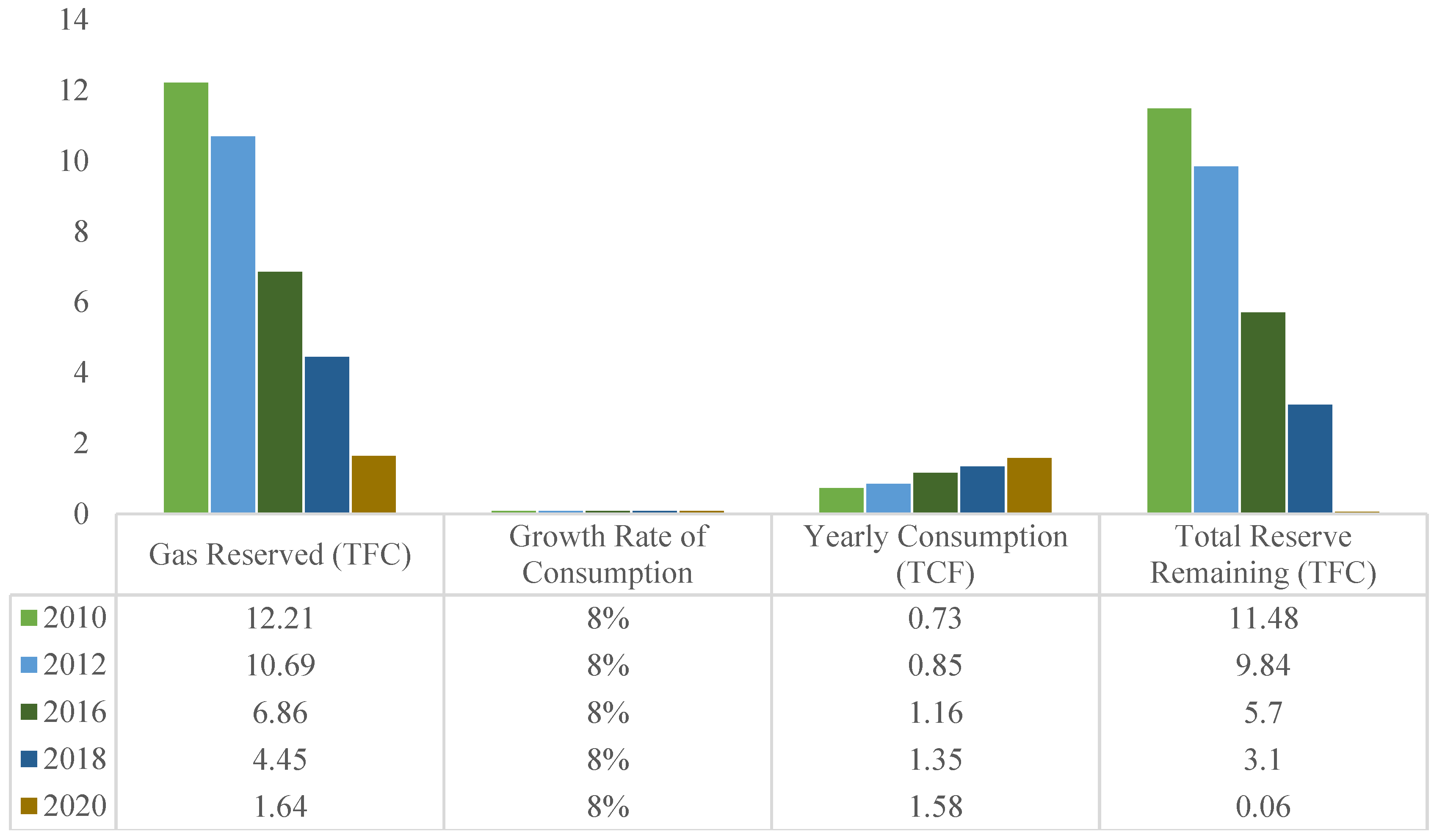
Figure 2.
Classification of Energy Storage System.
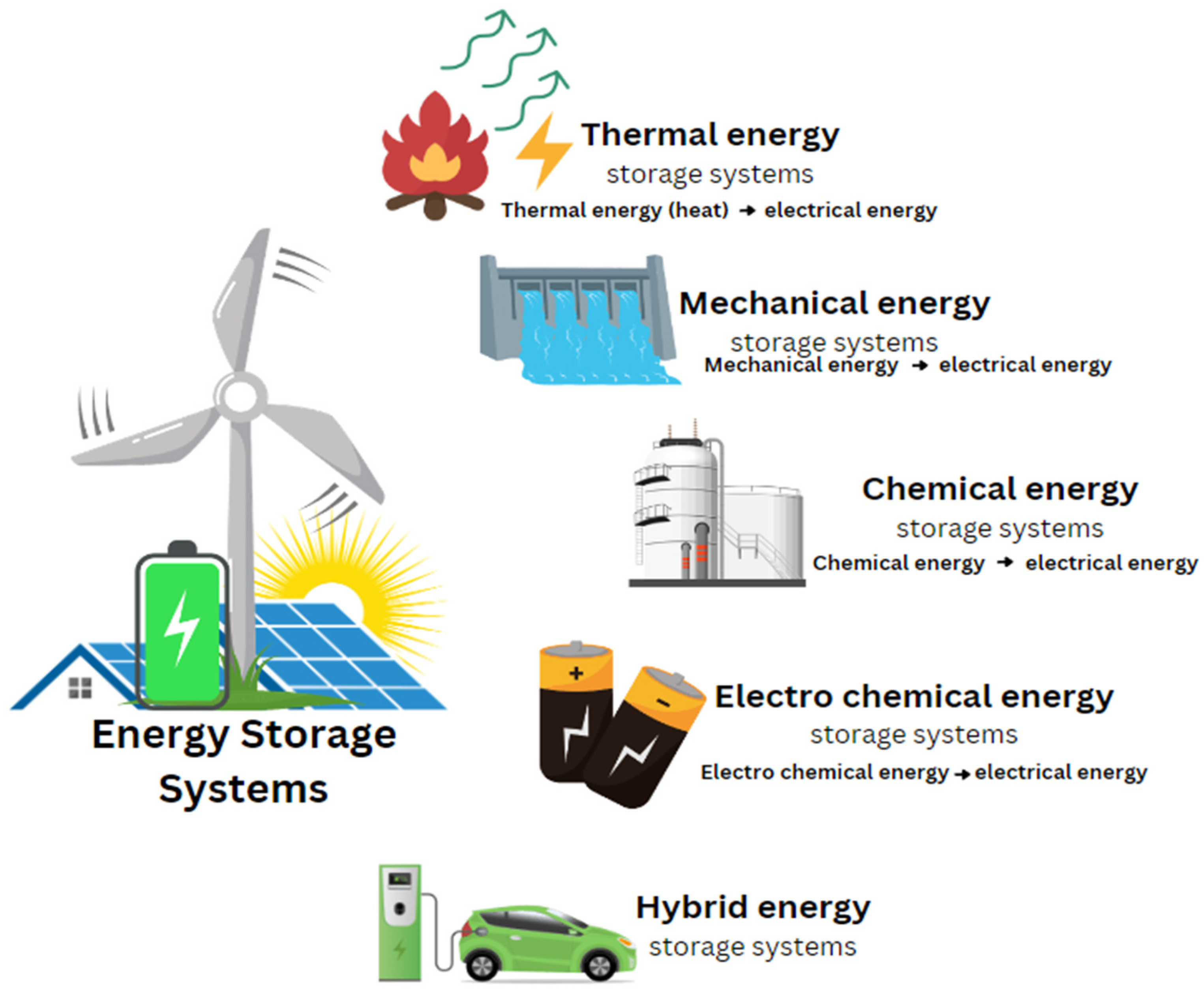
Figure 3.
Schematic of basic fuel cell construction.
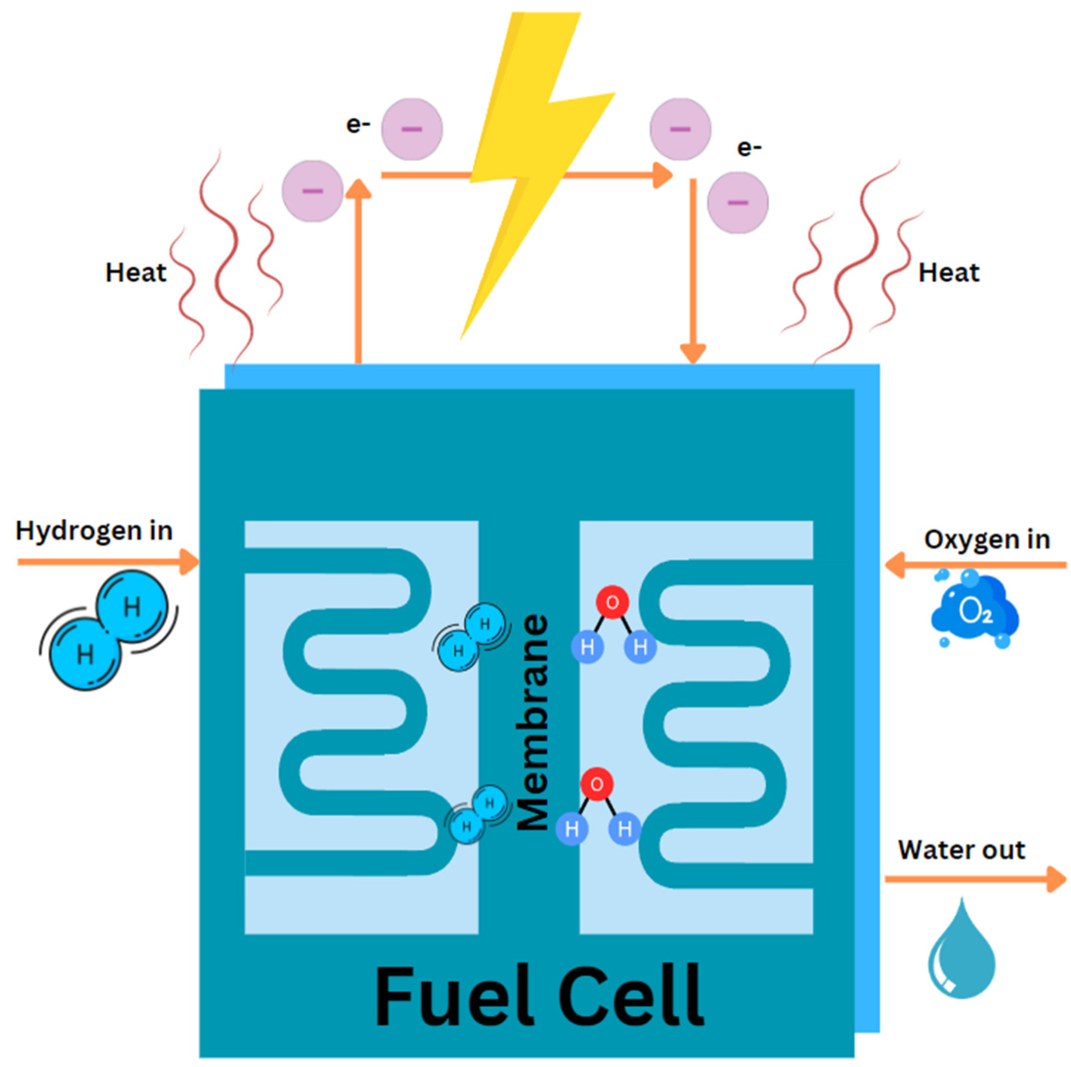
Figure 4.
Types of fuel cell.
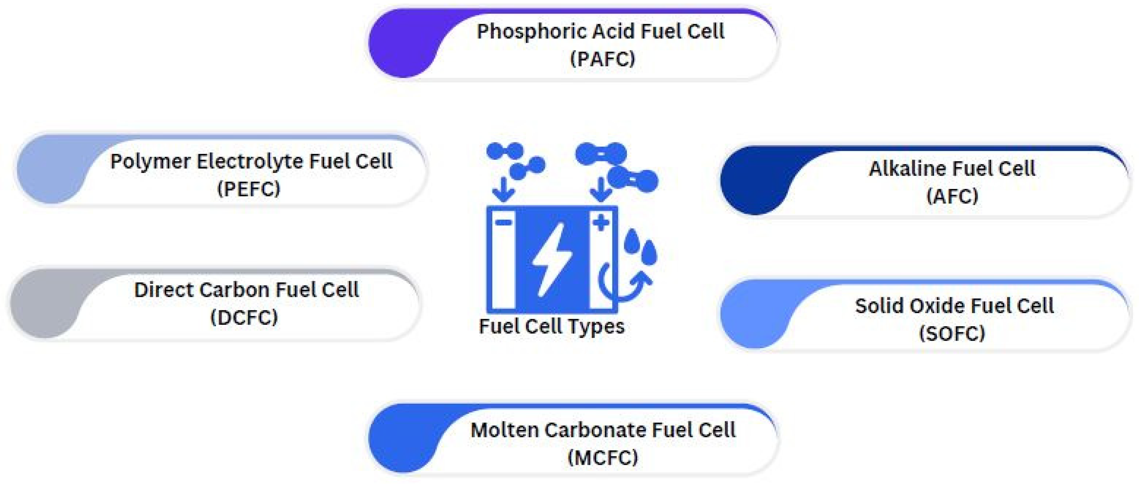
Figure 5.
Direct Carbon Fuel Cell (DCFC).
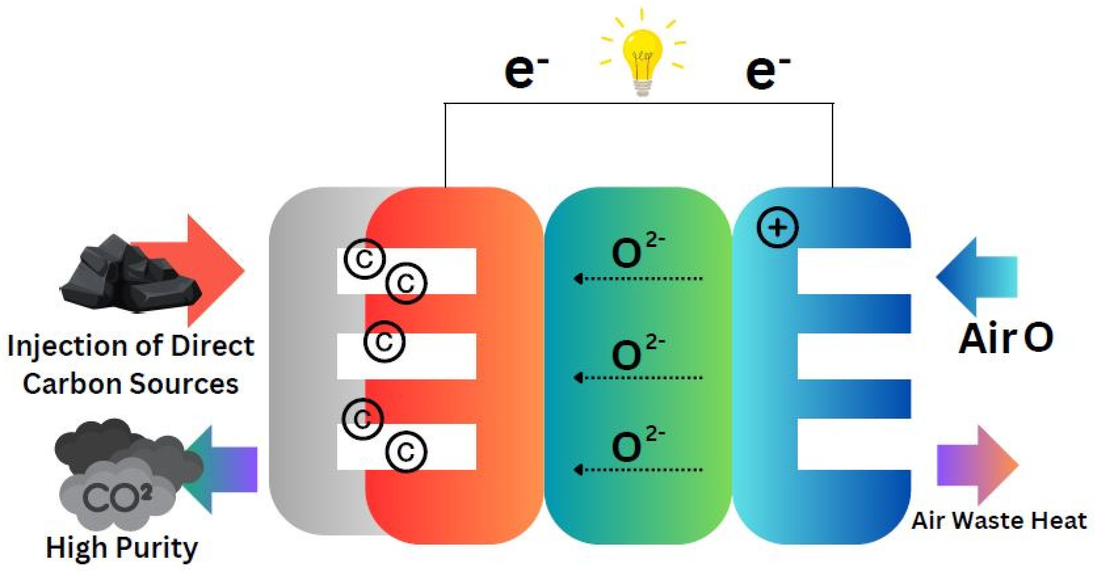
Figure 6.
Heat collected in the electrolyte QNaOH, structural components of the cell QNi, and total heat stored in the cell QNaOH + QNi.
Figure 6.
Heat collected in the electrolyte QNaOH, structural components of the cell QNi, and total heat stored in the cell QNaOH + QNi.
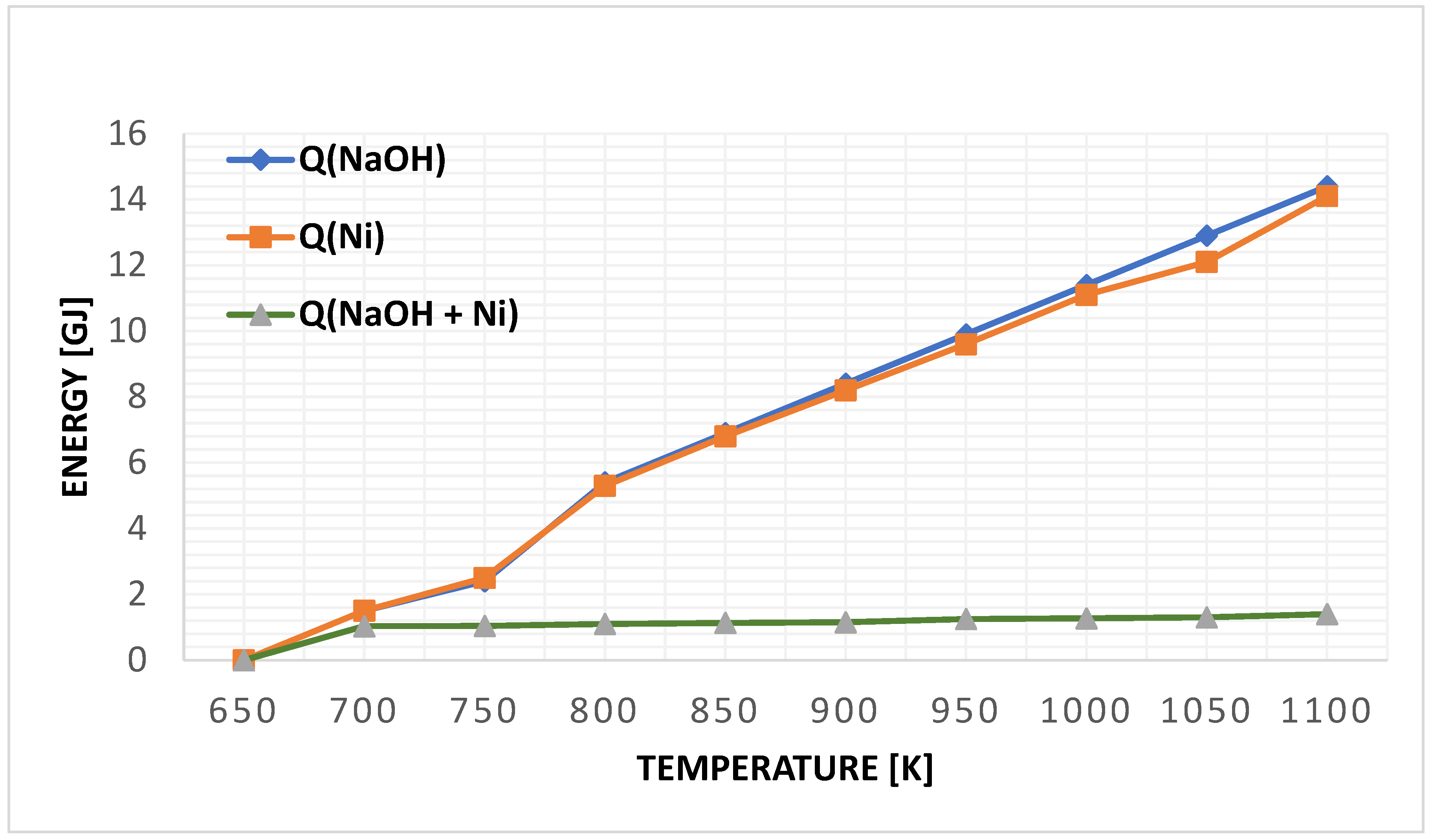
Figure 7.
Fuel cell temperatures vs time (hour) of electrical power of fuel cell of 25KW.
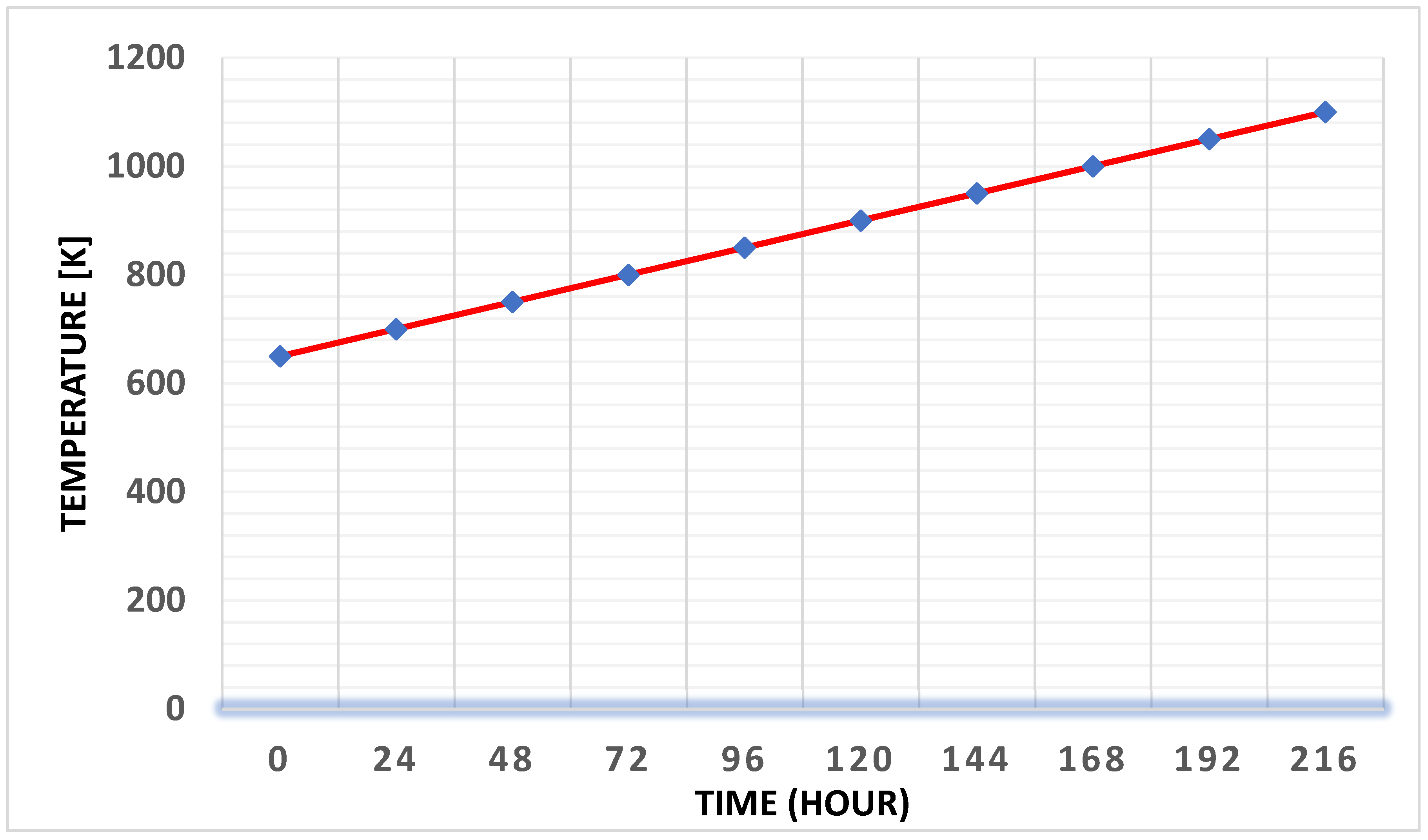
Figure 8.
Polymer Electrolyte Fuel Cell (PEFC).
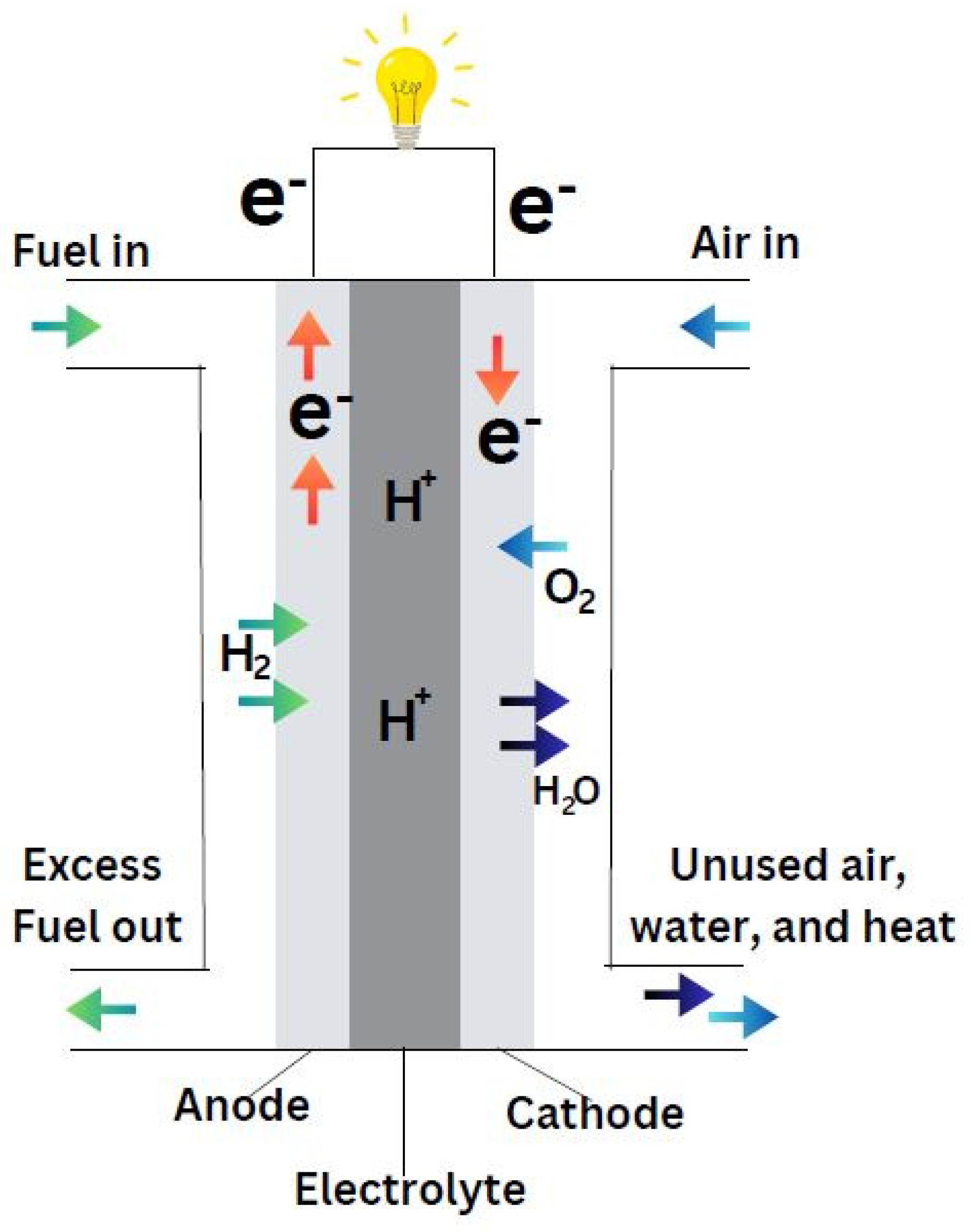
Figure 9.
Polarization curve (Voltage vs. Current Curve) for reference conditions for the Polymer Electron Membrane Fuel Cells (Ramírez-Cruzado et al., 2020).
Figure 9.
Polarization curve (Voltage vs. Current Curve) for reference conditions for the Polymer Electron Membrane Fuel Cells (Ramírez-Cruzado et al., 2020).
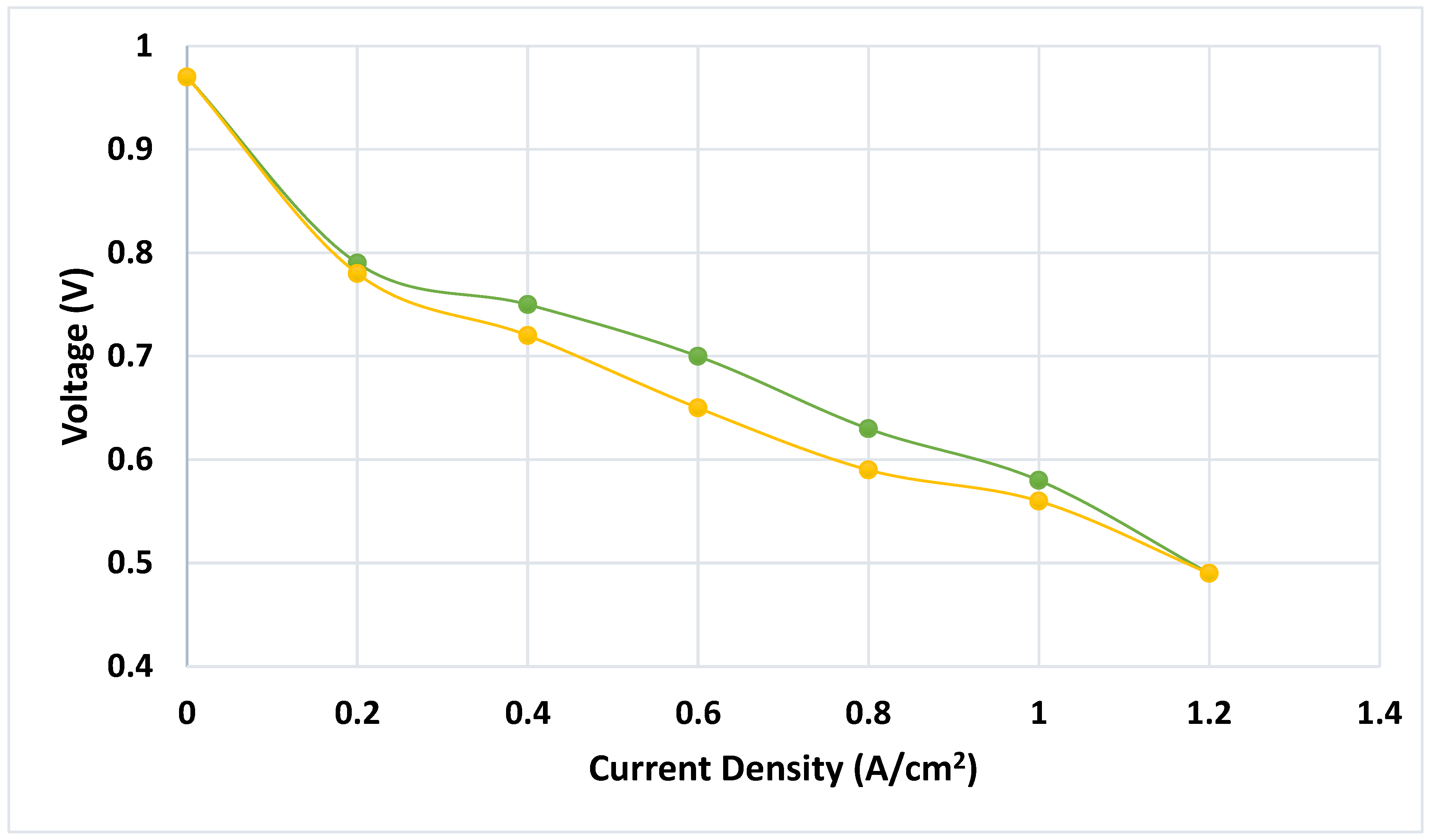
Figure 10.
Polarization curve for temperature tests (Voltage vs. Current Density) (Ramírez-Cruzado et al., 2020).
Figure 10.
Polarization curve for temperature tests (Voltage vs. Current Density) (Ramírez-Cruzado et al., 2020).
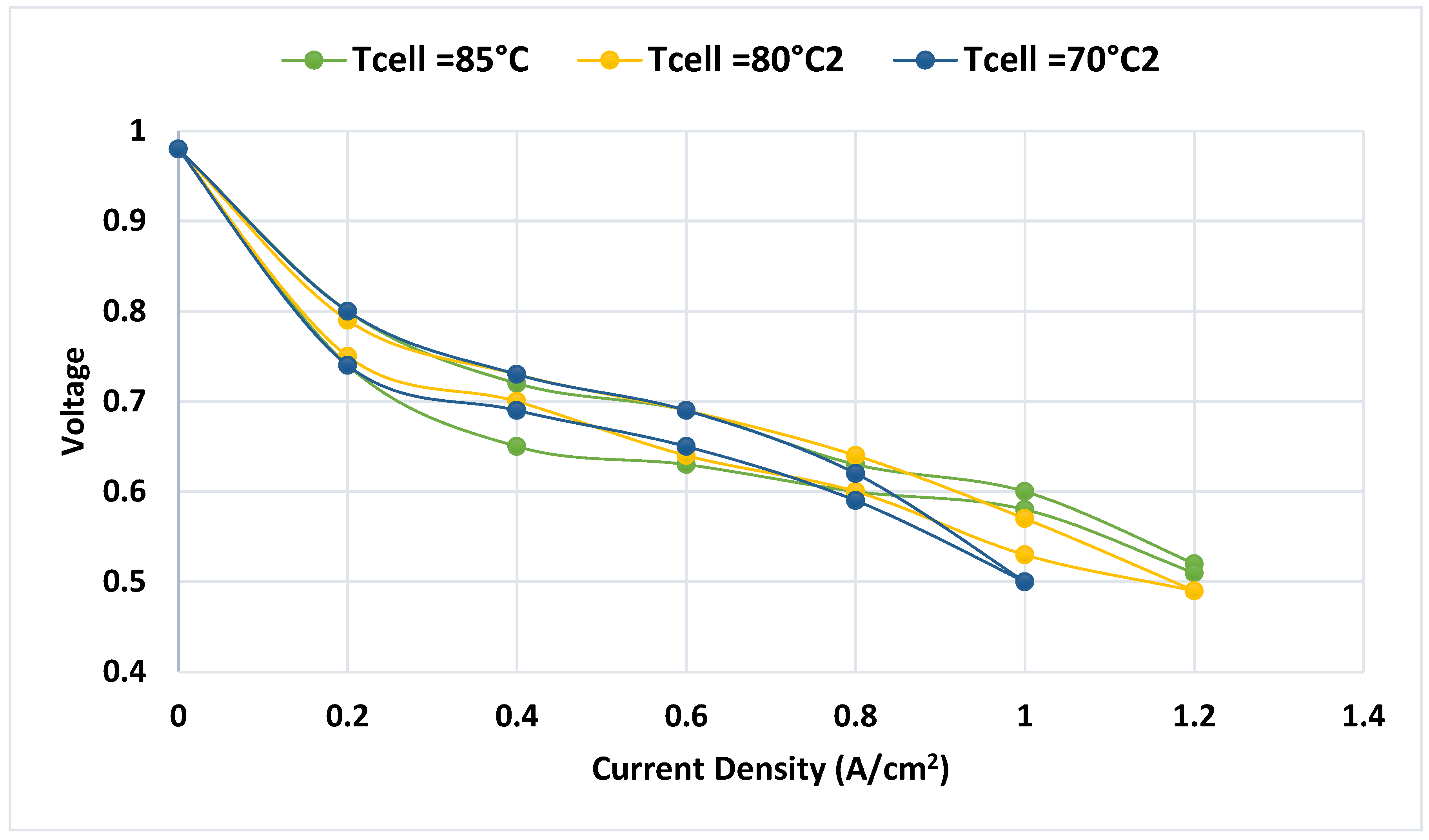
Figure 11.
The following performance curve exhibits he efficiency, current density, and the power output curve of the PEM fuel cells (Ramírez-Cruzado et al., 2020).
Figure 11.
The following performance curve exhibits he efficiency, current density, and the power output curve of the PEM fuel cells (Ramírez-Cruzado et al., 2020).
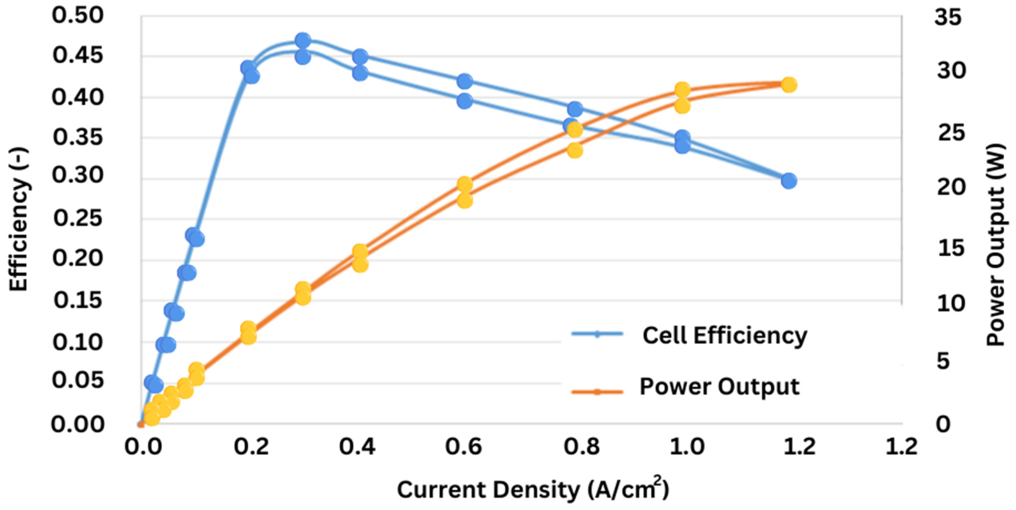
Figure 12.
Alkaline Fuel Cell (AFC).
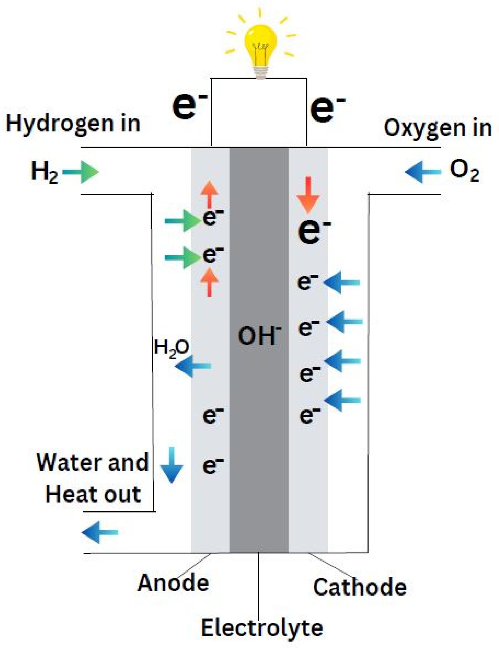
Figure 13.
Cell stability under relatively high anode/cathode dew points of 55/60 °C(Peng et al., 2020).
Figure 13.
Cell stability under relatively high anode/cathode dew points of 55/60 °C(Peng et al., 2020).
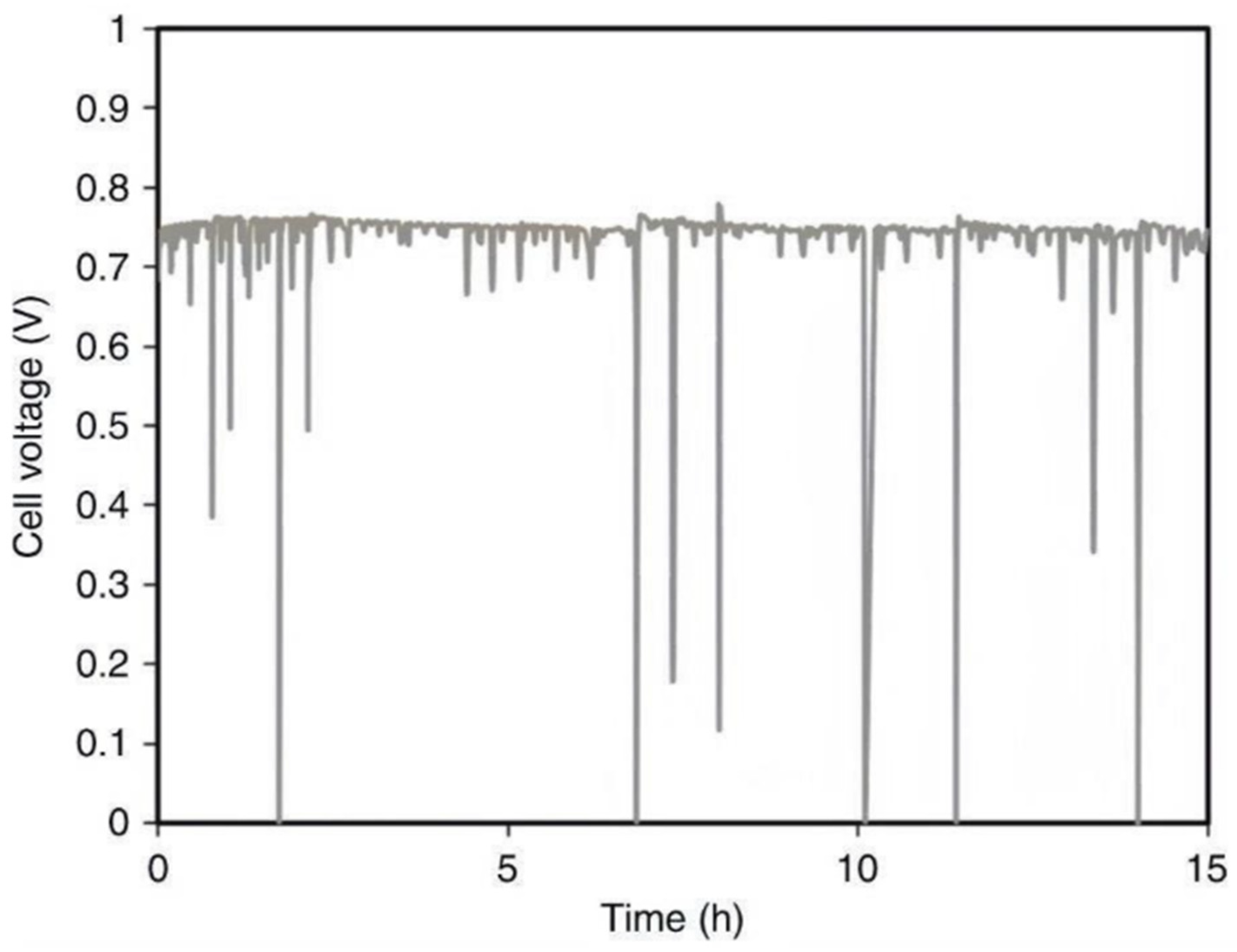
Figure 14.
Cell stability under optimized anode/cathode dew points of 53/55 °C(Peng et al., 2020).
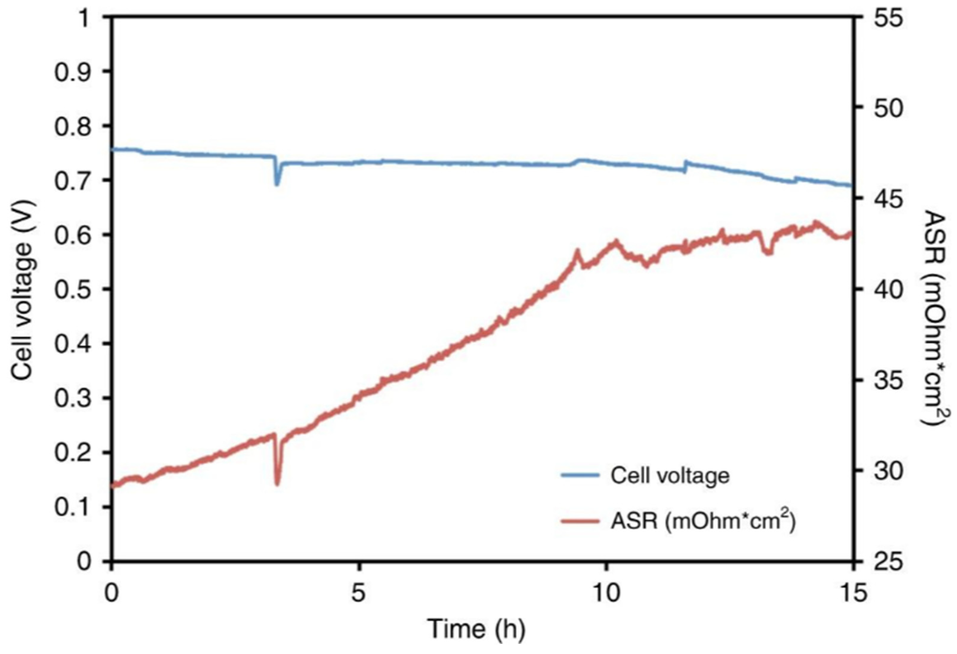
Figure 15.
i-V and i-Power Density Curves for an AMFC with 8% PTFE in the catalyst layer and 20% PTFE in the gas diffusion layer at H2/O2 and H2/Air (CO2-Free) conditions (Peng et al., 2020).
Figure 15.
i-V and i-Power Density Curves for an AMFC with 8% PTFE in the catalyst layer and 20% PTFE in the gas diffusion layer at H2/O2 and H2/Air (CO2-Free) conditions (Peng et al., 2020).
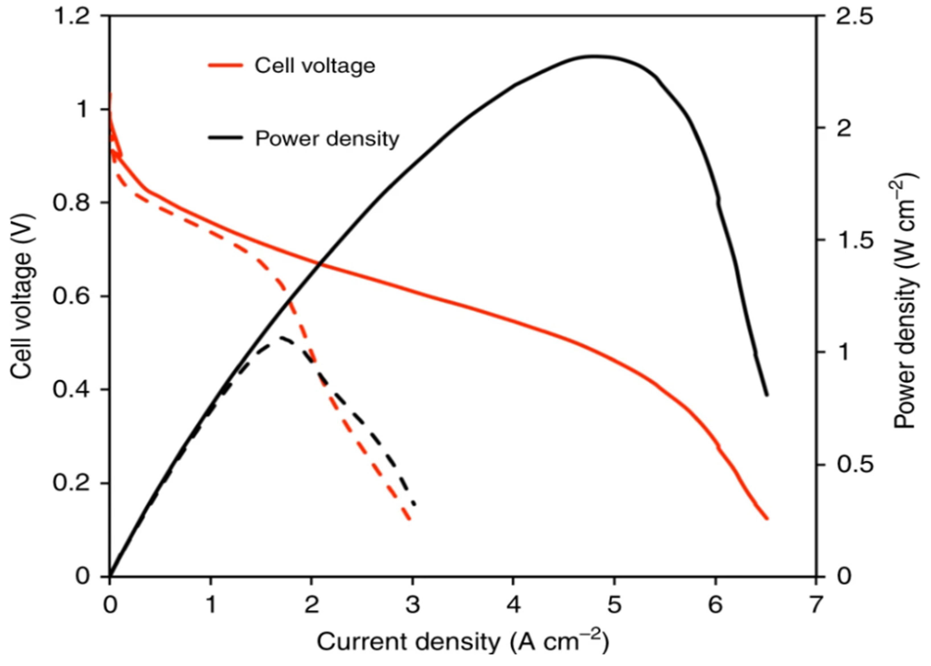
Figure 16.
Phosphoric Acid Fuel Cell (PAFC).
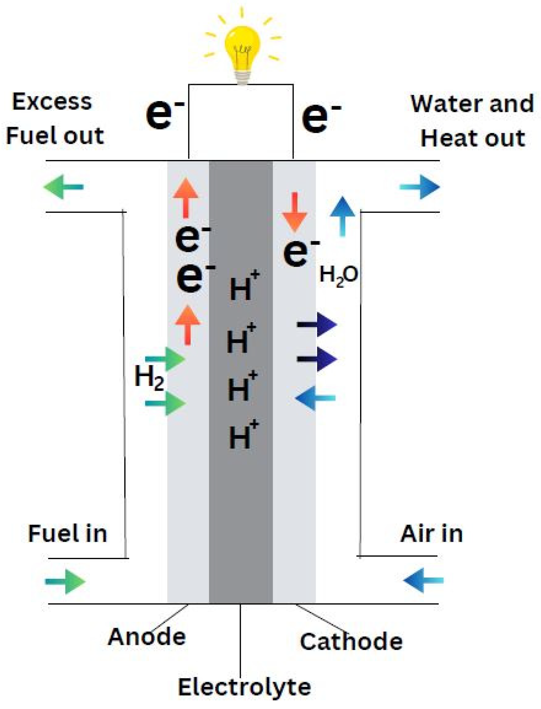
Figure 17.
Conductivity of HCl, HNO3, H2SO4, and H3PO4 as a Function of Concentration for PAFC.
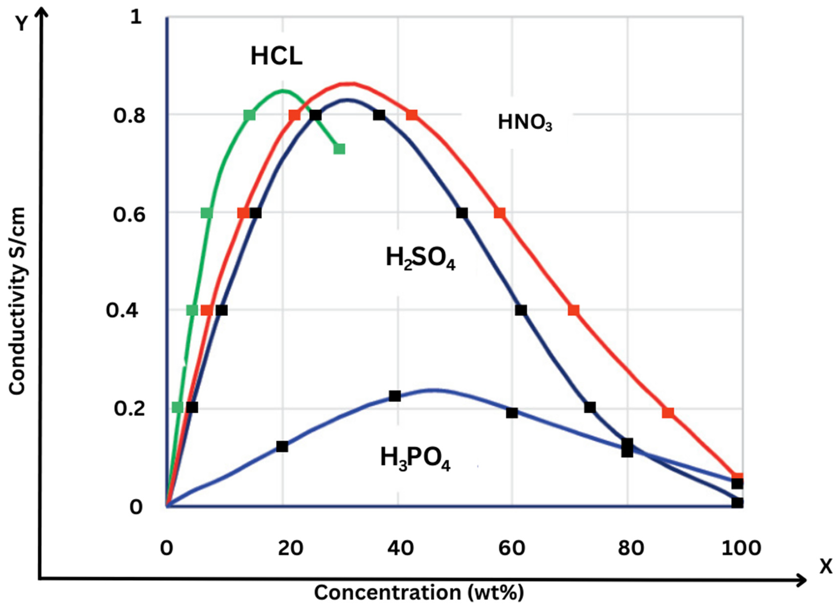
Figure 18.
Molten Carbonate fuel cell.
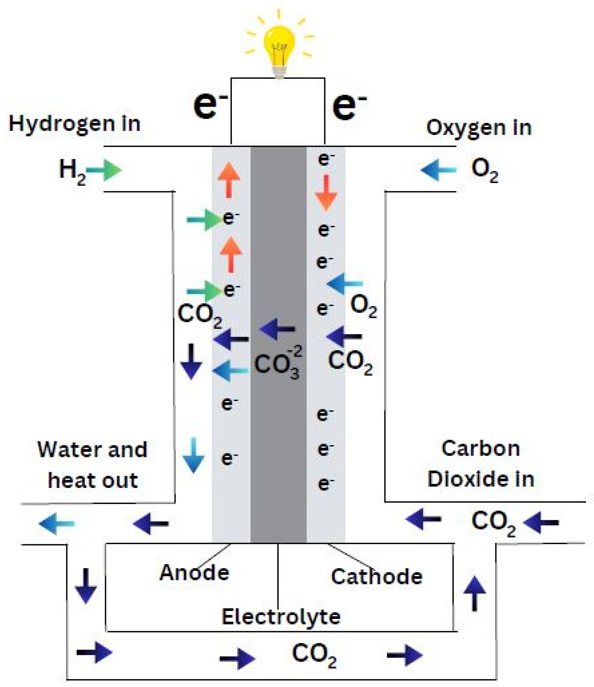
Figure 19.
Molten carbonate fuel cell polarization curve in the integrated structure (Ghorbani et al., 2022).
Figure 19.
Molten carbonate fuel cell polarization curve in the integrated structure (Ghorbani et al., 2022).
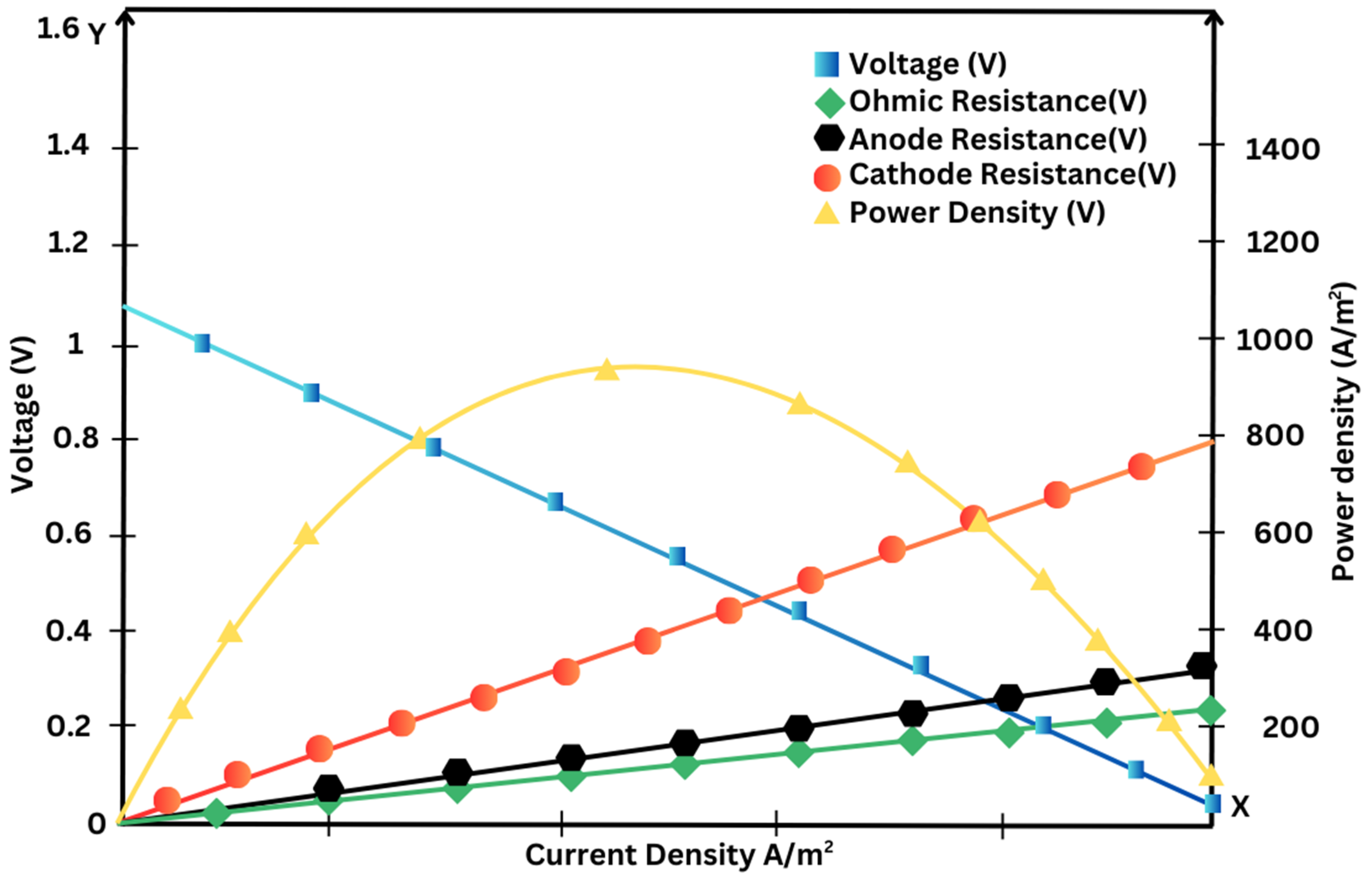
Figure 20.
Solid oxide fuel cell (SOFC).
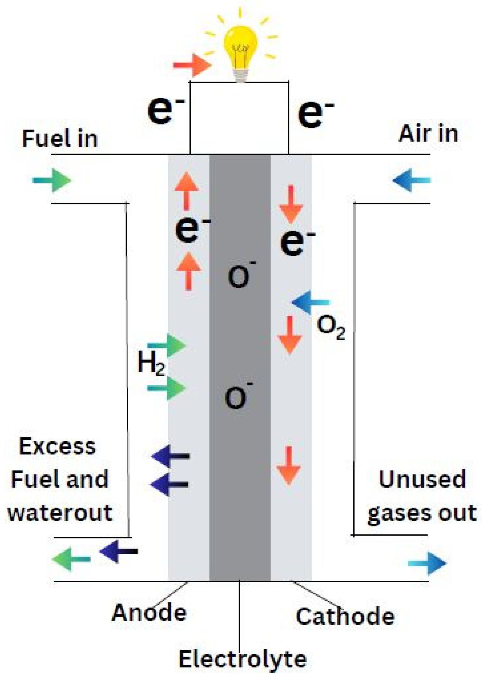
Figure 21.
V-I polarization curve of an SOFC. where T is the fuel cell temperature; T 0 = 973 K, γ = 0.2Ω, and β = −2870 K are the constant coefficients of the fuel cell; and r is the internal resistance of the SOFC.
Figure 21.
V-I polarization curve of an SOFC. where T is the fuel cell temperature; T 0 = 973 K, γ = 0.2Ω, and β = −2870 K are the constant coefficients of the fuel cell; and r is the internal resistance of the SOFC.
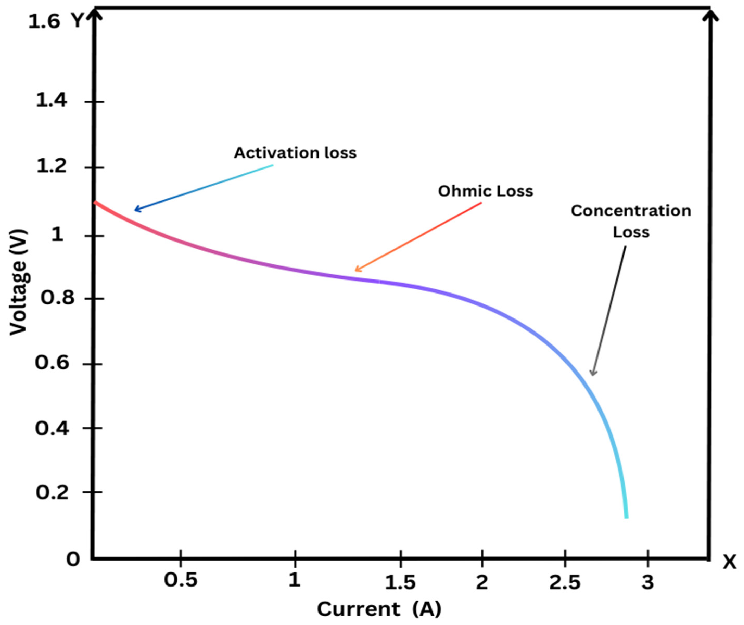
Figure 22.
Schematic of a hybrid stand-alone PV-WT-BT integrated with fuel cell.
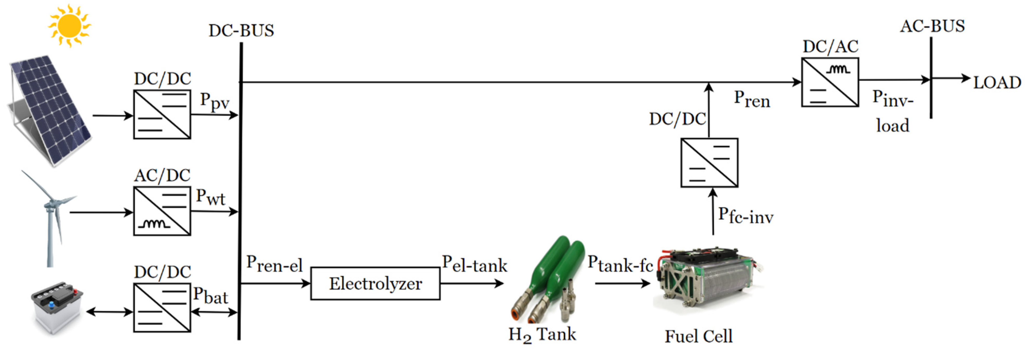
Figure 23.
Fuel cell applications.
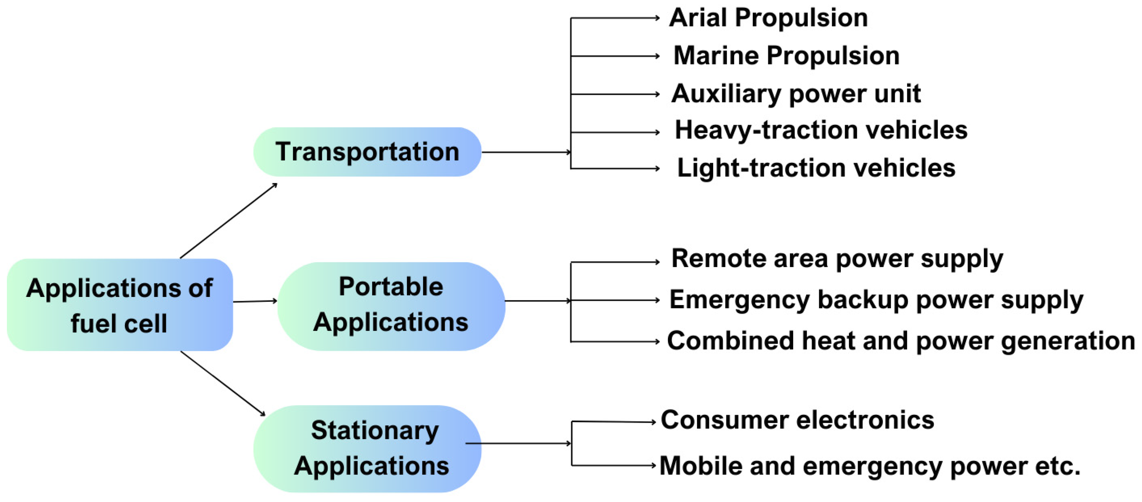
Figure 25.
System layout of the proposed SOFC-ICE integration for maritime applications. P.H.: Preheater, C.O.: Cooler, S.H. Superheater, Evap: Evaporator, Eco: Economiser.
Figure 25.
System layout of the proposed SOFC-ICE integration for maritime applications. P.H.: Preheater, C.O.: Cooler, S.H. Superheater, Evap: Evaporator, Eco: Economiser.
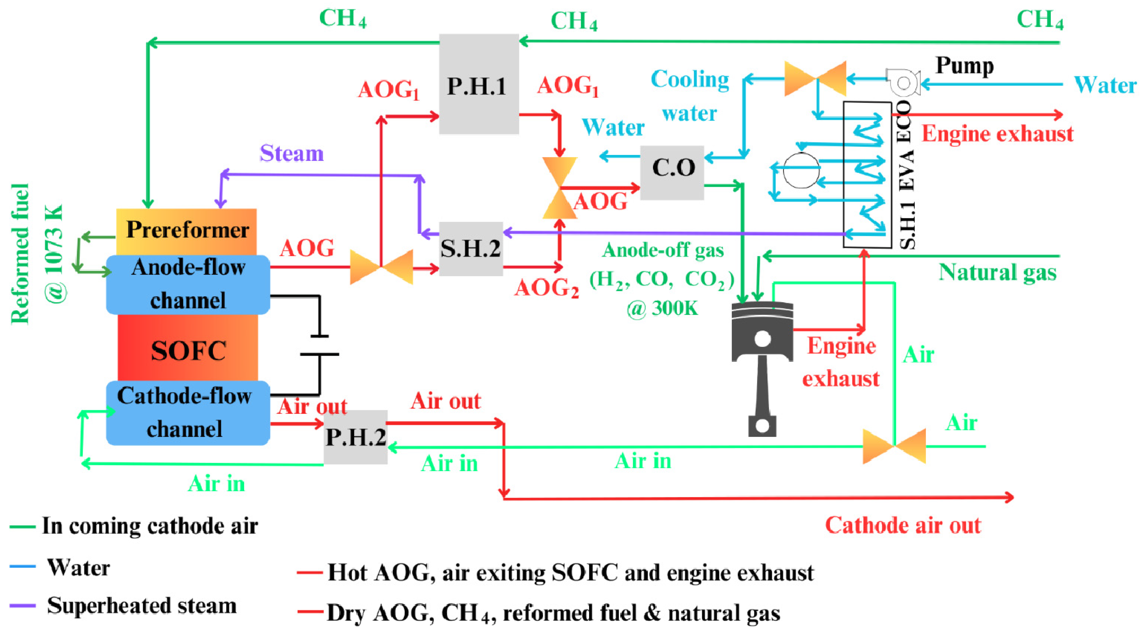
Figure 26.
Integration of Solid Oxide Fuel Cells (SOFCs) in Auxiliary Power Units (APUs) for Modern Hybrid Vehicles (Shen et al., 2016).
Figure 26.
Integration of Solid Oxide Fuel Cells (SOFCs) in Auxiliary Power Units (APUs) for Modern Hybrid Vehicles (Shen et al., 2016).
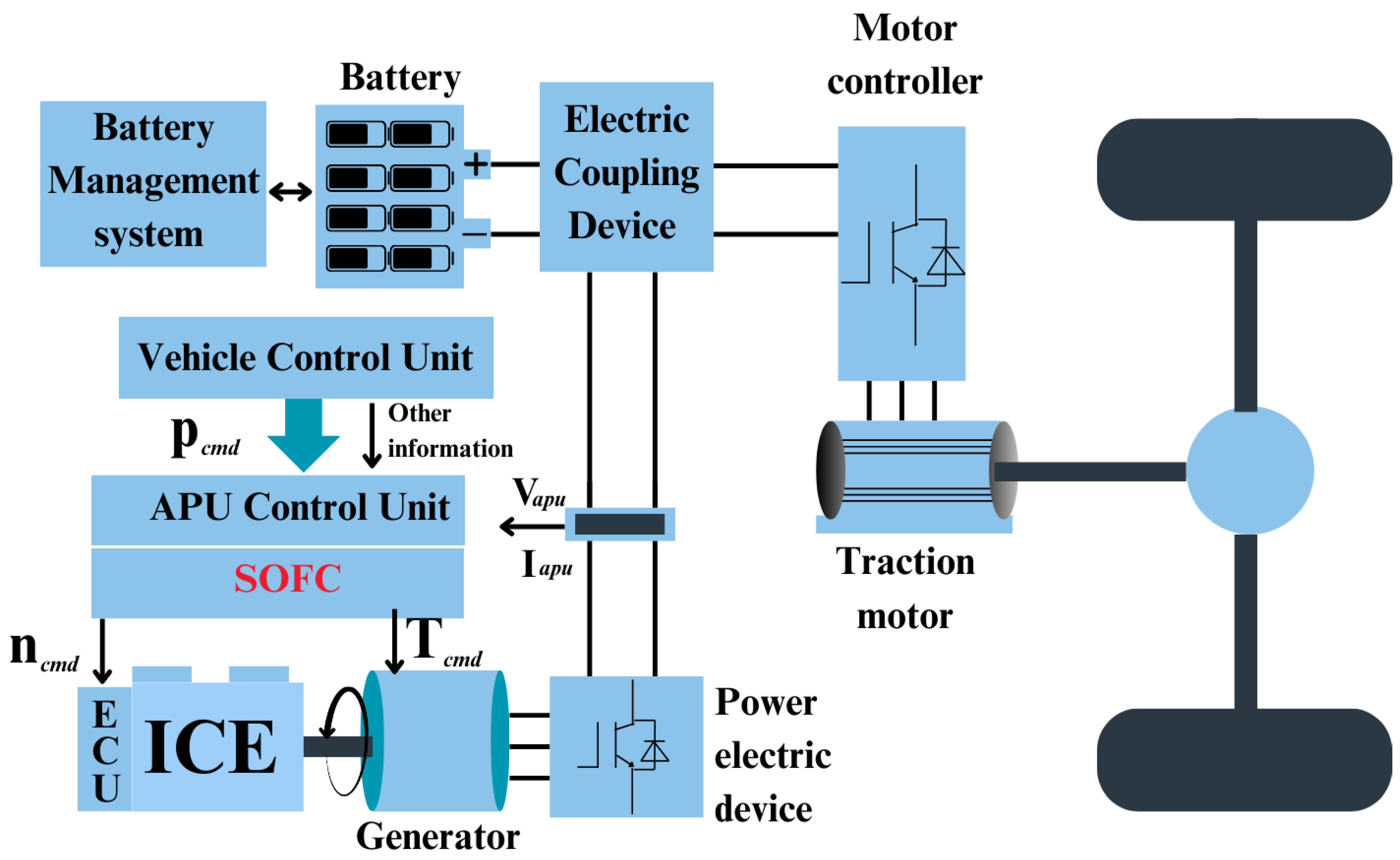
Figure 27.
XCIENT Fuel Cell Truck, a state of the art heavy duty truck by Hyundai (Hyundai, 2024).
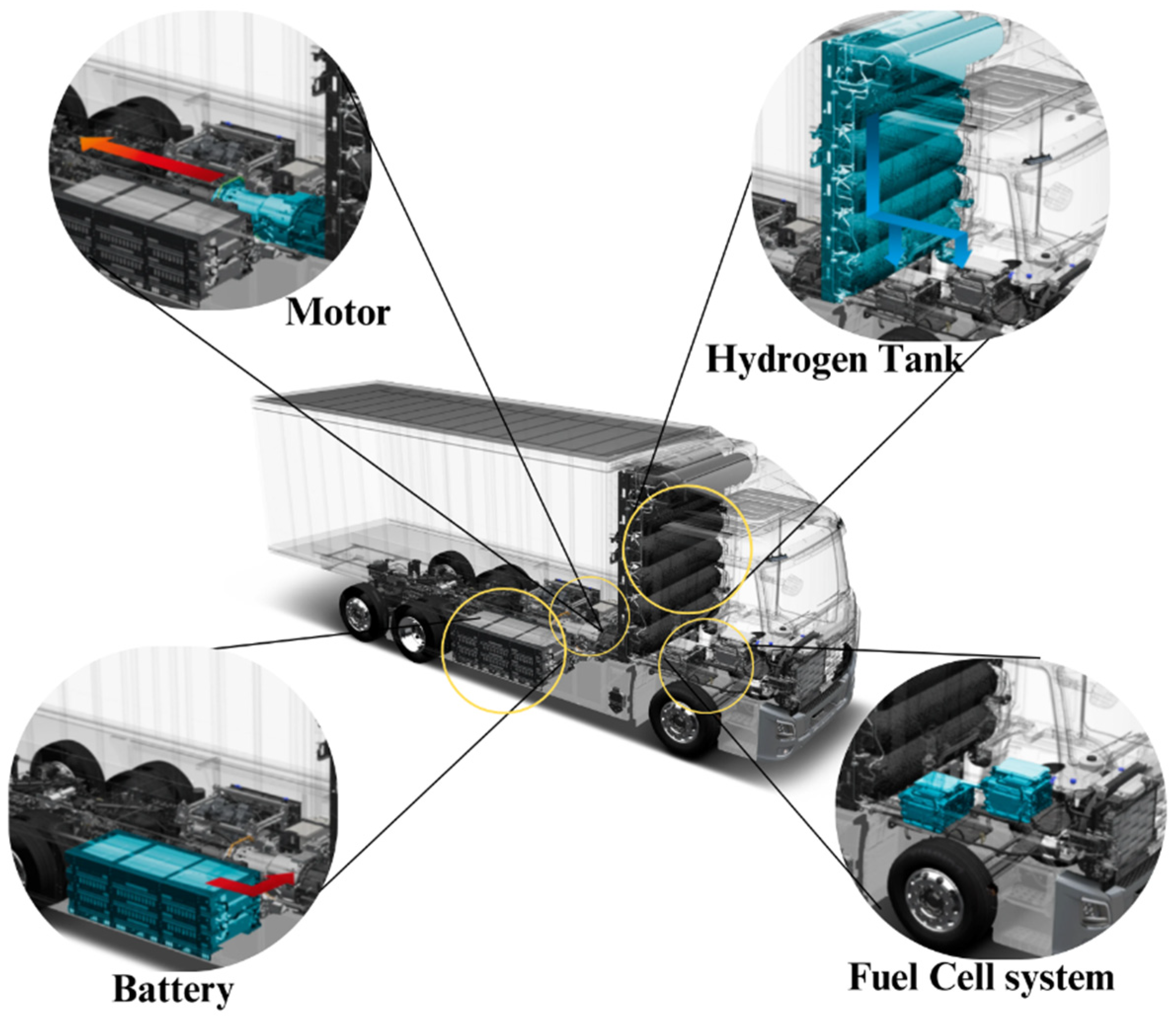
Figure 28.
Components of a Fuel Cell Electric Vehicle (FCEV): An Overview of the Hydrogen-Powered Drivetrain, from Hydrogen Storage to Power Conversion and Emission-Free Operation (U.S. Department of Energy, 2020).
Figure 28.
Components of a Fuel Cell Electric Vehicle (FCEV): An Overview of the Hydrogen-Powered Drivetrain, from Hydrogen Storage to Power Conversion and Emission-Free Operation (U.S. Department of Energy, 2020).
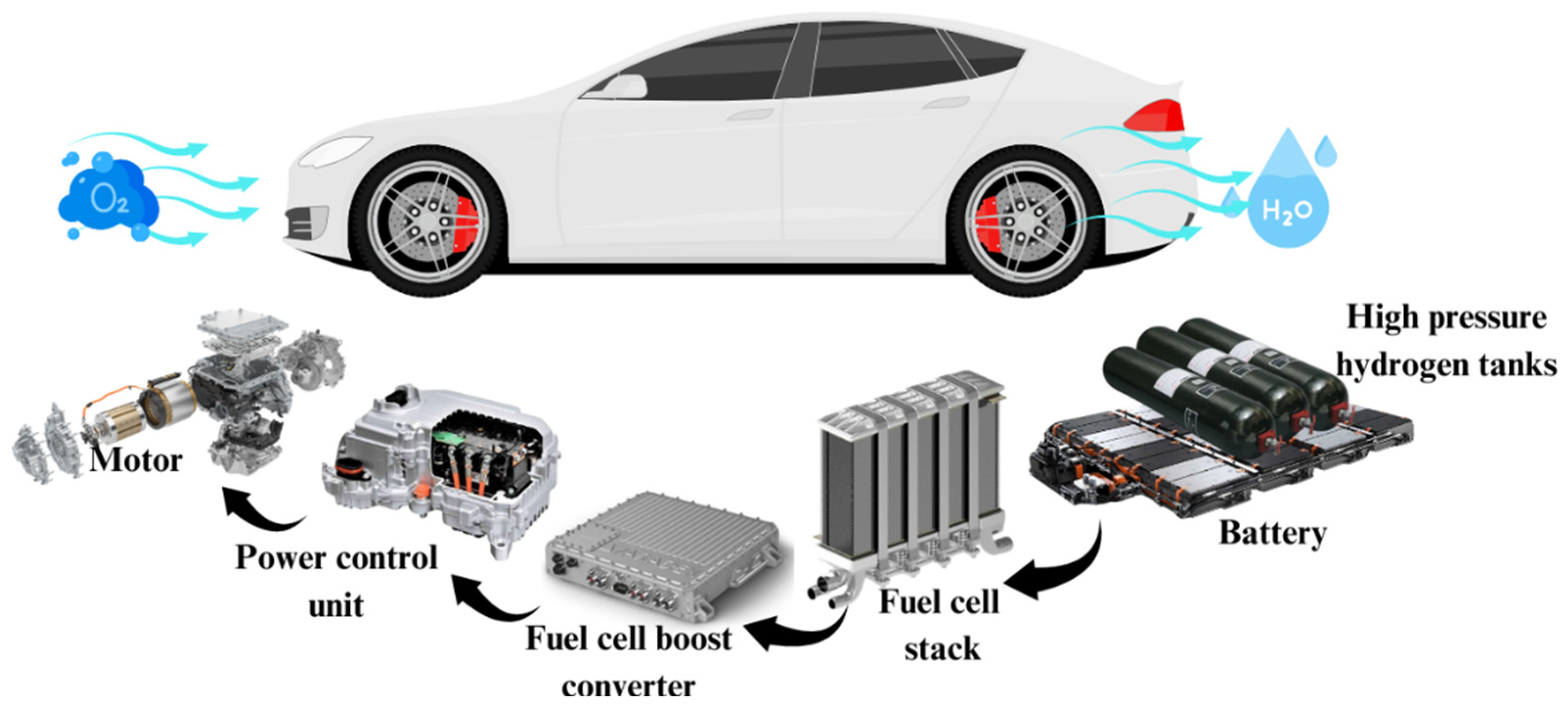
Figure 28.
Schematic of the simulated solar-hydrogen-fuel cell system for a Remote area power supply application (Nsour et al., 2019).
Figure 28.
Schematic of the simulated solar-hydrogen-fuel cell system for a Remote area power supply application (Nsour et al., 2019).
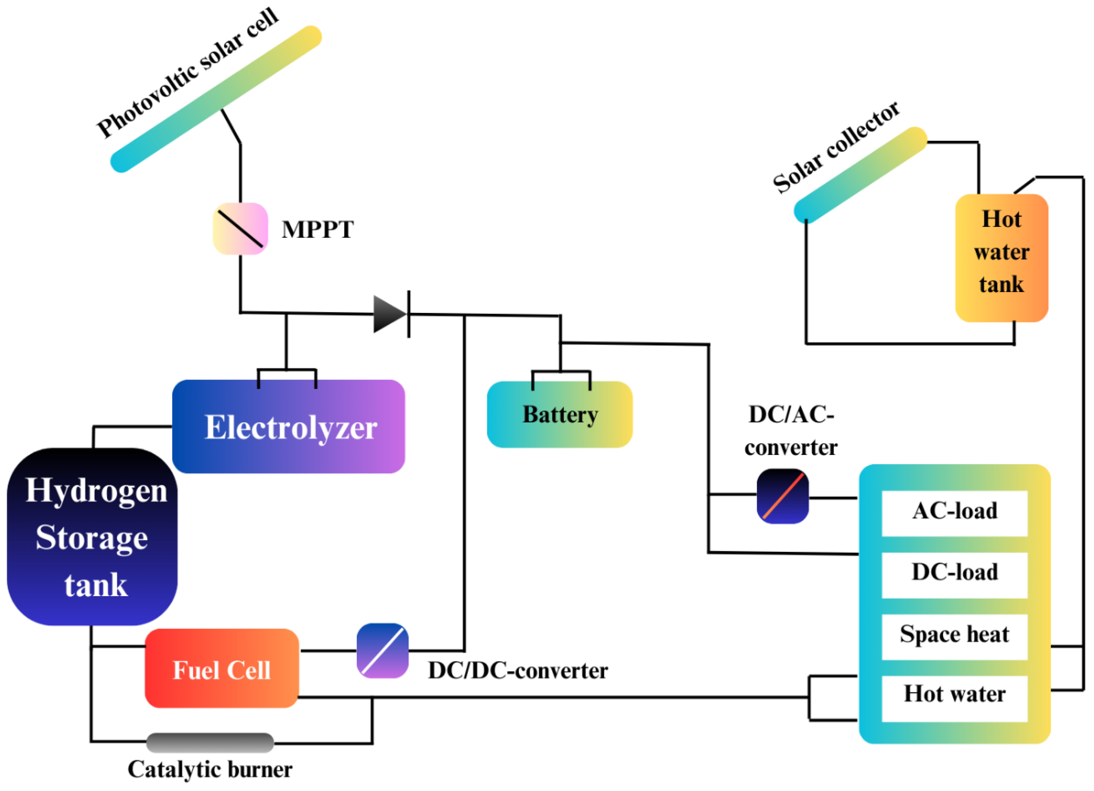
Figure 29.
Integration of fuel cells in emergency power supply (S. Zhang et al., 2023).
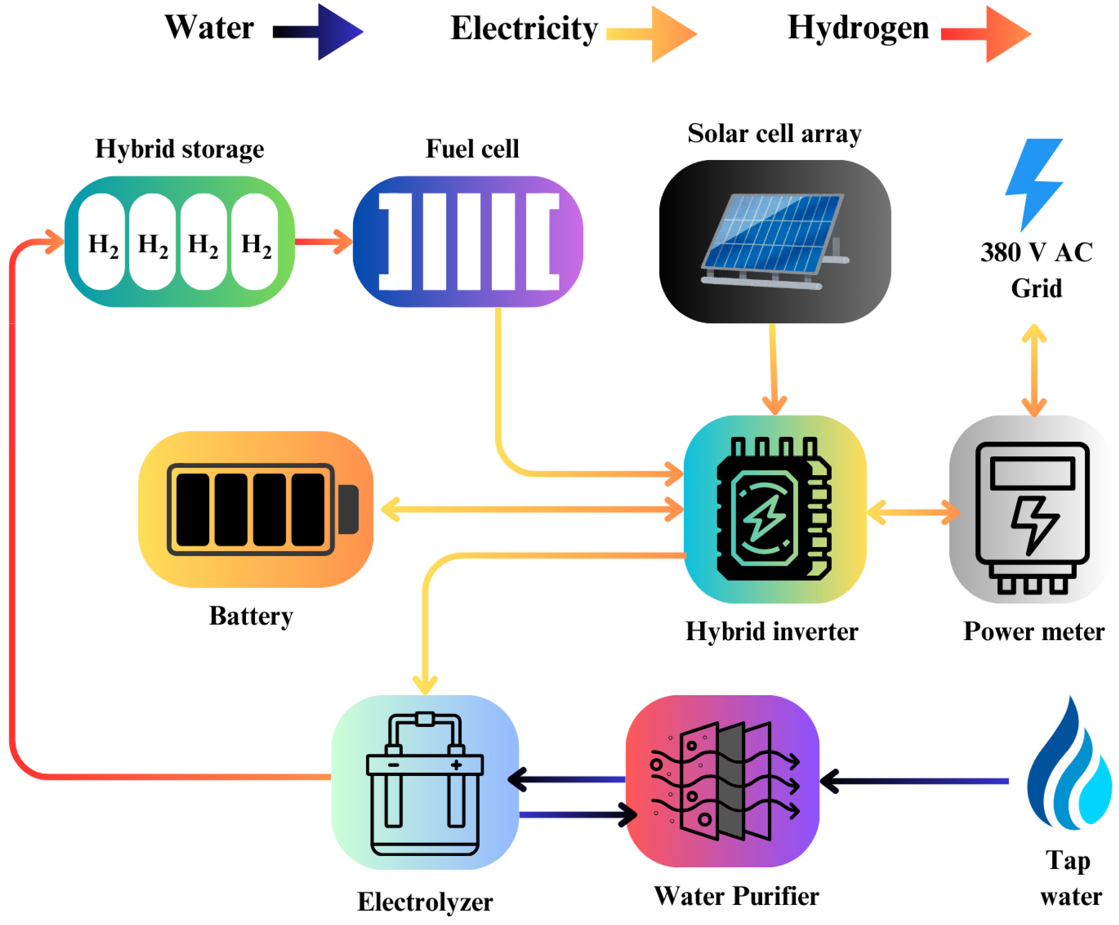
Figure 30.
The schematic diagram for fuel cell micro-CHP systems (Hawkes et al., 2009).
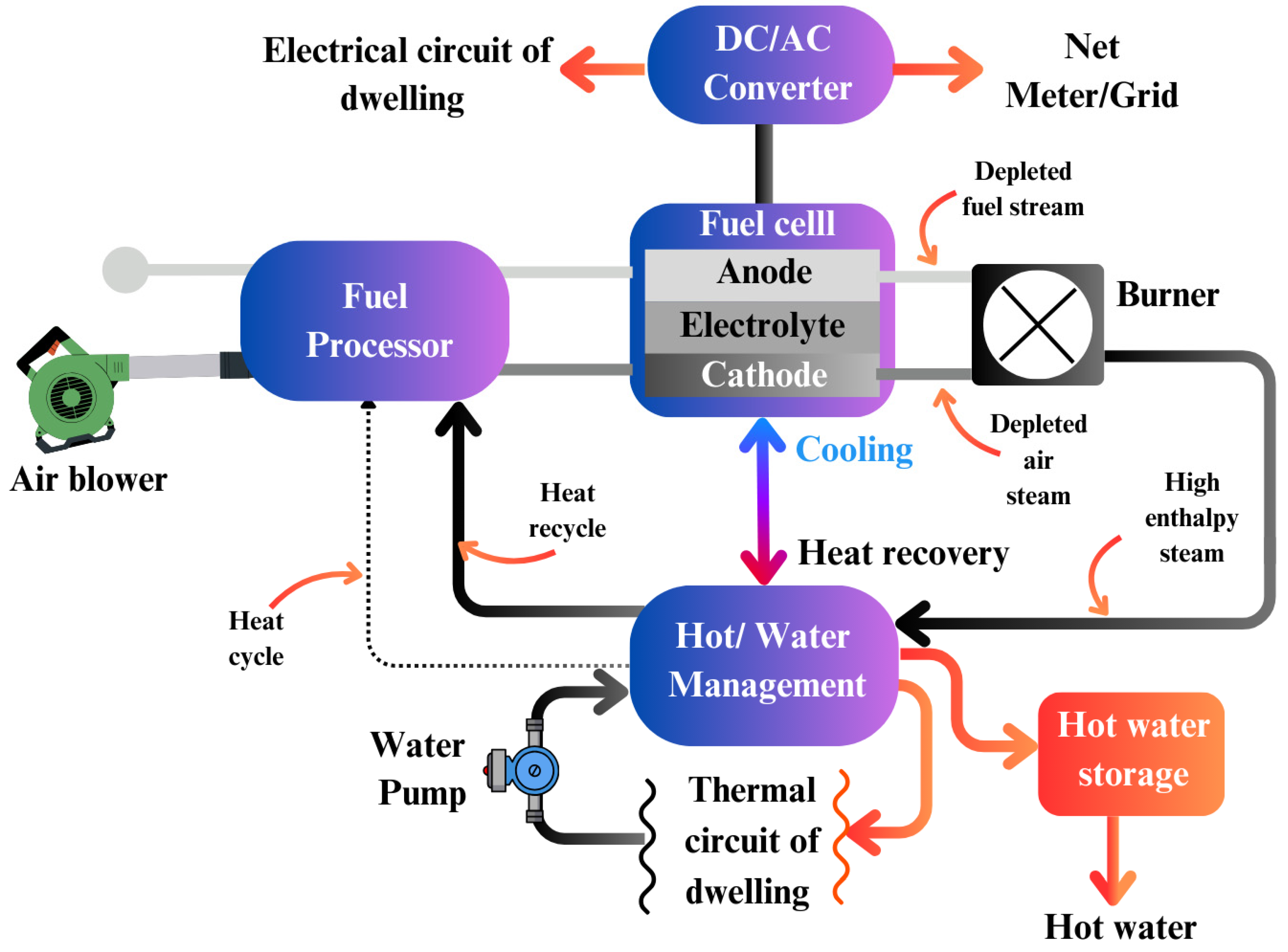
Figure 31.
Major challenges in fuel cell technology.
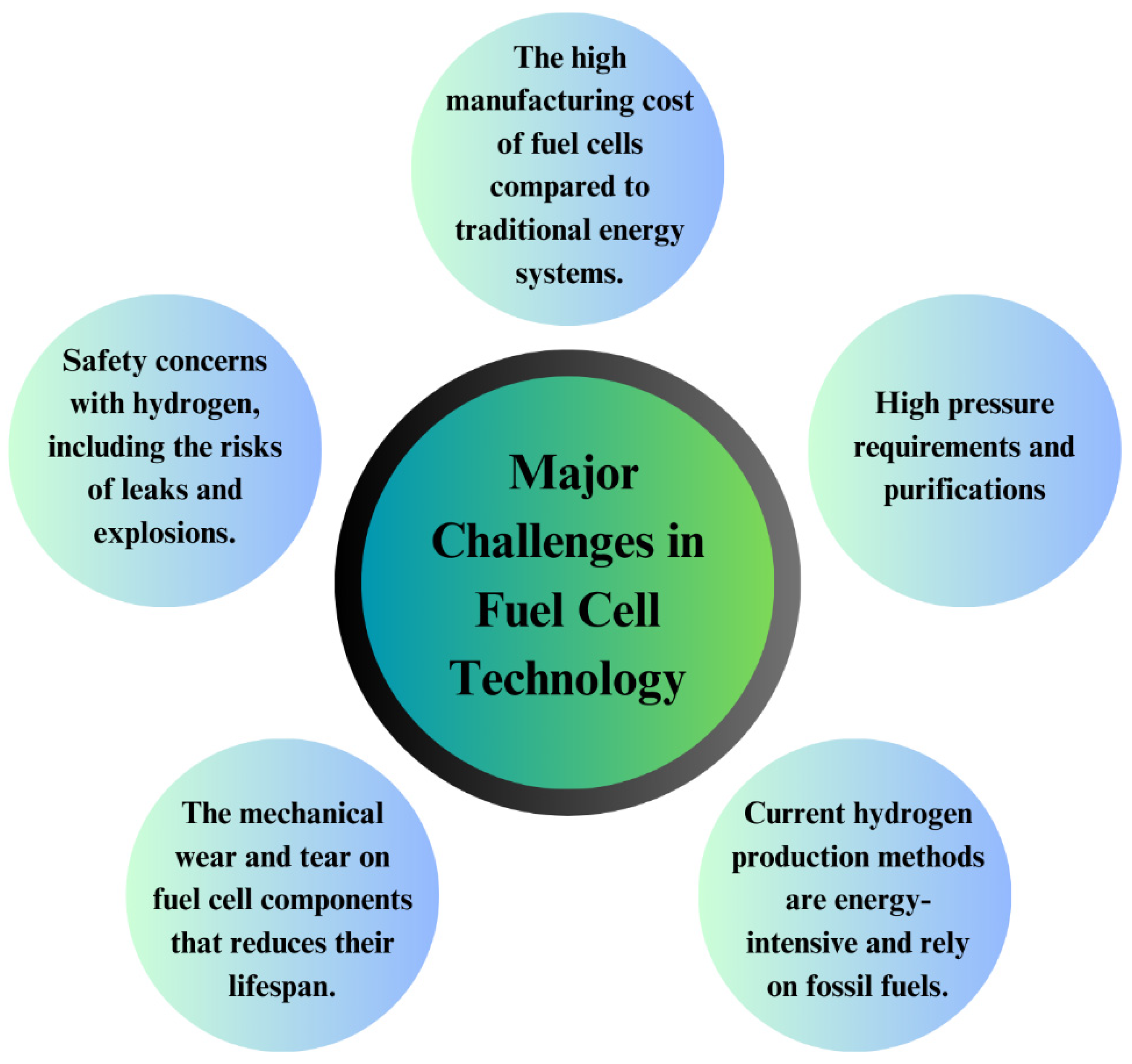
Table 1.
Comparison of fuel cells with other power generating systems (Kirubakaran et al., 2009), (Nahar & Kendall, 2011), (Larminie, 2003),(Winter & Brodd, 2004).
Table 1.
Comparison of fuel cells with other power generating systems (Kirubakaran et al., 2009), (Nahar & Kendall, 2011), (Larminie, 2003),(Winter & Brodd, 2004).
| Power source | Capacity range | Efficiency | Capital cost ($/kW) | O & M cost ($/kW) |
|---|---|---|---|---|
| Reciprocating engine: diesel | 500 kW–50 MW | 35% | 200–350 | 0.005–0.015 |
| Turbine generator | 500 kW–5 MW | 29–42% | 450–870 | 0.005–0.0065 |
| Photovoltaic | 1 kW–1 MW | 6–19% | 6600 | 0.001–0.004 |
| Wind turbine | 10 kW–1 MW | 25% | 1000 | 0.01 |
| Fuel cells | 200 kW–2 MW | 40–85% | 1500–3000 | 0.0019–0.0153 |
Table 2.
Classification of ESS based on the form of energy stored.
| Form of energy stored | Type of ESS | Example | References |
|---|---|---|---|
| Thermal energy | Sensible heat storage (SHS) | Liquid SHS, solid SHS | (Suresh & Saini, 2020) |
| Latent heat storage (LHS) or phase change materials (PCM) | Water ice, paraffin wax | (Salunkhe & D., 2017) | |
| Thermochemical energy storage (TCES) | Metal hydrides, ammoniates | (Desai et al., 2021) | |
| Pumped thermal energy storage (PTES) | Molten salt, water | (Sharma & Mortazavi, 2023) | |
| Mechanical energy | Pumped hydro energy storage (PHES) | Water reservoirs | (Rehman et al., 2015) |
| Gravity energy storage (GES) | Masses suspended on cables | (K. Chen, 2022) | |
| Compressed air energy storage (CAES) | Air compressed in underground caverns | (Y. Li et al., 2022) | |
| Flywheel energy storage (FES) | Rotating disks | (Arani et al., 2017) | |
| Chemical energy | Hydrogen energy storage | Hydrogen gas | (Eberle et al., 2009) |
| Synthetic natural gas (SNG) storage | Methane gas | (Fendt et al., 2019) | |
| Solar fuel storage | Synthetic fuels such as methanol and ethanol | (Schüth, 2011) | |
| Battery energy storage (BES) | Lead-acid batteries, lithium-ion batteries | (Pang et al., 2021) | |
| Electro-chemical energy | Lead acid | (Skyllas-Kazacos, 2010) | |
| NiCd | (Jayaprabakar et al., 2023) | ||
| Li | (Zheng et al., 2020) | ||
| NaS, redox flow, hybrid flow |
(Skyllas-Kazacos, 2010) | ||
| Electrical Storage Systems | Superconducting Magnetic Energy Storage (SMES) | (Vulusala G & Madichetty, 2018) | |
| Capacitor | (Kinjo et al., 2006) | ||
| Supercapacitors, Ultracapacitors. | (Lemian & Bode, 2022) | ||
Table 3.
Some characteristics of important fuel cells (Basu, 2007).
| Types | PEMFC | DMFC | AFC | PAFC | MCFC | SOFC |
|---|---|---|---|---|---|---|
| Primary applications | Automatic and Stationary power | Portable power | Space vehicles and drinking water | Stationary power | Stationary power | Vehicle auxiliary power |
| Electrolyte | Polymer membrane | Polymer membrane | Concentrated (30-50 %) KOH in H2O | Concentrated (30-50) KOH in H2O | Molten Carbonate retained in a ceramic matrix of LiAlO2 | Yttrium stabilized Zirkonia |
| Operating temperature range | 50-100℃ | 0-60℃ | 50-200℃ | 150-250℃ | 600-700℃ | 700-1000℃ |
| Charge carrier | H+ | H+ | OH- | H+ | CO3-2 | O-2 |
| Prime cell components | Carbon-based | Carbon-based | Carbon-based | Graphite based | Stainless steel | Ceramic |
| Catalyst | Platinum | Pt-Pt/Ru | Platinum | Platinum | Platinum | Perovskites |
| Primary fuel | H2 | Methanol | H2 | H2 | H2, CO, CH4 | H2, CO |
| Start-up time | Sec-min | Sec-min | Sec-min | Hours | Hours | Hours |
| Power density (KW/m3) | 3.8-6.5 | ̴0.6 | ̴1 | 0.8-1.9 | 1.5-2.6 | 0.1-1.5 |
| Combined cycle fuel cell efficiency | 50-60 % | 30-40 % | 50-60 % | 55.00% | 55-65 % | 55-65 % |
Table 4.
Summary of Investigations on Direct Carbon Fuel Cells (DCFCs).
| Author | Type of Investigation | Electrolyte | Findings |
|---|---|---|---|
| (Kouchachvili & Ikura, 2011) | Experimental Study | Ternary eutectic (43.4 mol % Li2CO3 – 31.2 mol% Na2CO3 – 25.4 mol % K2CO3) spiked by 20 wt % Cs2CO3 | Achieved a maximum power output of 49 mW/cm² at 700°C with petroleum coke as fuel. |
| (Campanari et al., 2013) | Analytical Study | Coal-derived fuels | Explored the application of DCFCs in large-scale coal-fired power cycles, highlighting potential efficiency improvements. |
| (W. Wu et al., 2017) | Experimental Study | Gd:CeO2-Li/Na2CO3 composite electrolyte | Demonstrated direct electrochemical oxidation of solid carbon at 500–600°C, achieving high power densities. |
| (Saddawi & Virginia, 2005) | Experimental Study | Not specified | Found that coal-derived rods perform significantly better than graphite counterparts due to increased electrochemical activity. |
| (Cui et al., 2021) | Review Article | Molten carbonate | Discussed various DCFC designs and materials, emphasizing the need for further research to enhance performance and durability. |
| (J. J. Chen et al., 2015) | Review Article | Not specified | Reviewed the current status of DCFC technology, highlighting recent progress and technical challenges. |
| (T. Han et al., 2024) | Experimental Study | Not specified | Investigated the role of MgO catalysts in enhancing the electrochemical performance of DCFCs. |
| (W. Wu et al., 2018) | Experimental Study | Gd:CeO2-Li/Na2CO3 composite electrolyte | Demonstrated high power densities and carbon utilization at temperatures below 600°C. |
| (Cao et al., 2007) | Review Article | Not specified | Compared DCFCs to other fuel cell types, highlighting their higher attainable efficiency and lower carbon emissions. |
Table 5.
Recent Research on Polymer Electrolyte Fuel Cell (PEFC).
| Author | Type of Investigation | Electrolyte | Findings |
|---|---|---|---|
| (Overton et al., 2023) | Synthesis of Poly(arylimidazole) via Polycondensation | Poly(arylimidazole) | Developed a method to control molecular mass by end-capping, enabling functionalization to poly(arylimidazolium)s. |
| (Duan et al., 2023) | Synergistic Utilization of CeO2-Anchored Bifunctionalized Metal–Organic Frameworks | Polymer Nanocomposite | Achieved high power density and durability in PEMFCs by incorporating CeO2-anchored bifunctionalized MOFs. |
| (Jeon et al., 2023) | Customized Patterning of Deep Nanowell Structures in Polymer Electrolyte Membranes | Polymer Electrolyte Membranes | Enhanced fuel cell performance through deep nanowell structures, improving ion conductivity and water management. |
| (X.-L. Zhang et al., 2023) | Plasma-Assisted Synthesis of Metal Nitrides for Anion-Exchange-Membrane Fuel Cells | Metal Nitrides | Developed efficient platinum-group-metal-free catalysts for anion-exchange-membrane fuel cells using plasma-assisted synthesis. |
| (Lee et al., 2022) | Cation Effects in Proton Exchange Membrane Fuel Cells | Cation Effects | Investigated the impact of cations on PEMFC performance, contributing to a comprehensive understanding of fuel cell behavior. |
| (Ahn et al., 2020) | Regeneration of Hydrogen Sulfide Contaminated PEFCs | Regeneration Method | Developed a method to recover 95–100% of the original performance of hydrogen sulfide-contaminated PEFCs, enhancing fuel cell longevity. |
| (Kovtunenko & Karpenko-Jereb, 2021) | Study of Voltage Cycling Conditions on Pt Oxidation and Dissolution | Platinum Catalyst Degradation | Studied the electrochemical behavior of Pt catalyst under various operating conditions, highlighting the impact of voltage cycling on Pt degradation. |
| (Tran et al., 2023) | Informatics-Driven Selection of Polymers for Fuel-Cell Applications | Polymer Selection | Employed informatics-based schemes to identify new polymer candidates for PEM, anode ionomer, and cathode ionomer applications. |
Table 6.
Research Studies on Alkaline Fuel Cells (AFCs) and Electrolyte Investigations.
| Author | Type of Investigation | Electrolyte | Findings |
|---|---|---|---|
| (McLean, 2002) | Review of AFC Technology | Aqueous Potassium Hydroxide (KOH) | AFCs offer high power densities and long lifetimes in specific applications, competing favorably with ambient air PEM fuel cells. However, they are sensitive to CO2 in the oxidant stream, leading to performance degradation. |
| (Brushett et al., 2012) | Development of Flowing Electrolyte Systems | Flowing KOH Electrolyte | Flowing electrolyte systems enhance heat and water management, facilitating carbonate removal and improving CO2 tolerance up to approximately 100 ppm. This approach extends AFC lifetimes compared to stationary electrolyte systems. |
| (J. Yang, 2006) | Workshop Report on AFCs | Aqueous KOH and Anion-Exchange Membranes | Alkaline membrane fuel cells (AMFCs) offer significant advantages over traditional PEM fuel cells, including increased electrocatalytic activity in alkaline conditions and the potential for non-precious metal catalysts. However, challenges remain in membrane stability and conductivity. |
| (Ferriday & Middleton, 2021) | Review of AFC Technology | Aqueous KOH | This review summarizes progress, bottleneck issues, and highlights recent research trends within the field of AFCs, emphasizing the need for further research to overcome existing challenges. |
| Urquidi-Macdonald et al., 2005 | Experimental Investigation of Carbon-Tolerant AFCs | Aqueous KOH | Successful tests of a technique for coating electrodes with polystyrene, in conjunction with other methods, appear to solve the problem of carbon poisoning in AFCs, making them more suitable for practical applications. |
| Kim et al., 2022 | Controlled Doping of Electrocatalysts | Aqueous KOH | Controlled doping of electrocatalysts through engineering impurities enhances hydrogen oxidation reaction (HOR) activity in alkaline conditions, offering a pathway to develop platinum-free catalysts for electrochemical energy conversion devices. |
| Bundschu et al., 2023 | Mechanistic Study of Spinel Metal Oxides | Aqueous KOH | This study identifies a novel theoretical pathway for the oxygen reduction reaction (ORR) on cubic Co3O4 nanoparticle electrocatalysts, aligning more closely with experimental results than previous models. |
| Huang et al., 2023 | Operando X-ray Studies of Bimetallic Oxide Electrocatalysts | Aqueous KOH | Multimodal operando synchrotron X-ray diffraction and resonant elastic X-ray scattering reveal the interplay between structure and oxidation state in Co-Mn spinel oxide electrocatalysts during the ORR, providing insights into degradation mechanisms. |
Table 8.
Summary of MCFC Research Findings.
| Author | Type of Investigation | Electrolyte | Findings |
|---|---|---|---|
| (Ferguson & Tarrant, 2021) | Techno-economic assessment of MCFCs for post-combustion CO2 capture | Lithium-Potassium Carbonate | Achieved 92% CO2 capture with 42% additional power production and a 2.6% thermal efficiency penalty compared to conventional amine scrubbing. |
| (Ferguson & Tarrant, 2021) | Technological review of MCFCs | Lithium-Potassium Carbonate | MCFCs can attain high-energy efficiencies, almost 60% in some cases, and overall fuel efficiencies exceeding 80% when applied in a cogeneration context. |
| (Lu et al., 2021) | Performance testing of a 10 kW MCFC | Lithium-Potassium Carbonate | Characterized and analyzed key materials of a single cell, providing insights into performance metrics. |
| (Shikhar et al., 2021) | Feasibility study of coproduction using internal reforming MCFC | Lithium-Potassium Carbonate | Explored flexible coproduction of hydrogen and power, demonstrating the potential for high-efficiency operation modes. |
| (Desmaele et al., 2019) | Atomistic simulations of molten carbonates | Lithium-Potassium Carbonate | Provided quantitative calculations of thermodynamic and transport properties, aiding in the development of technological devices and understanding geochemical processes. |
| (Berg & Findlay, 2009) | Modeling mass transport phenomena in MCFC cathodes | Lithium-Potassium Carbonate | Presented one-dimensional models of MCFC cathodes, assessing ion transport and optimization of diffusivity to enhance cell performance and longevity. |
| (Contreras et al., 2021) | Technological review of MCFCs | Lithium-Potassium Carbonate | MCFCs can attain high-energy efficiencies, almost 60% in some cases, and overall fuel efficiencies exceeding 80% when applied in a cogeneration context. |
| (Desmaele et al., 2019) | Atomistic simulations of molten carbonates | Lithium-Potassium Carbonate | Provided quantitative calculations of thermodynamic and transport properties, aiding in the development of technological devices and understanding geochemical processes. |
| (Berg & Findlay, 2009) | Modeling mass transport phenomena in MCFC cathodes | Lithium-Potassium Carbonate | Presented one-dimensional models of MCFC cathodes, assessing ion transport and optimization of diffusivity to enhance cell performance and longevity. |
| (Ferguson & Tarrant, 2021) | Techno-economic assessment of MCFCs for post-combustion CO2 capture | Lithium-Potassium Carbonate | Achieved 92% CO2 capture with 42% additional power production and a 2.6% thermal efficiency penalty compared to conventional amine scrubbing. |
Table 9.
Advancements and Investigations in Solid Oxide Fuel Cells (SOFCs).
| Author | Type of Investigation | Electrolyte | Findings |
|---|---|---|---|
| (Nam et al., 2024) | Catalyst Coating Technology | Yttria-stabilized Zirconia (YSZ) | Developed a catalyst coating process that significantly enhances SOFC performance in just four minutes. |
| (Y. Yang et al., 2024) | Reversible SOFCs | Yttria-stabilized Zirconia (YSZ) | La₀.₆Sr₀.4CoO3 (LSC) exhibits 3–10 times higher conductivity than LSM, enhancing catalytic activity in SOFC mode. |
| (Marcantonio & Scopel, 2024) | Thermodynamic Models | Yttria-stabilized Zirconia (YSZ) | Mixing hydrogen with methane reduces electrical efficiency but improves overall system efficiency due to lower internal temperature gradients. |
| (J. Li et al., 2024) | SOFC Technology Advancements | Yttria-stabilized Zirconia (YSZ) | SOFCs offer high efficiency up to 60% and minimal environmental impact, with superior energy efficiency compared to other fuel cell technologies. |
| (Ghaebi & Soleymani, 2025) | Thermodynamic Analysis | Yttria-stabilized Zirconia (YSZ) | Investigated the effect of parameters in the SOFC cycle using the response surface method. |
| (Corigliano et al., 2022) | SOFC Energy Systems | Yttria-stabilized Zirconia (YSZ) | SOFCs are fuel-flexible, highly efficient, and environmentally sustainable, with great potential in the energy transition process. |
| (Wehrle et al., 2022) | SOFC Performance Optimization | Yttria-stabilized Zirconia (YSZ) | Proposed a multiscale modeling methodology to evaluate the direct impact of cell materials and morphologies on commercial-scale system performance. |
| (Machado et al., 2022) | Functional Thin Films | Samarium-doped Ceria (SDC) | Implemented ultrathin bilayers of samarium-doped ceria and nanocomposites to enhance SOFC performance and durability. |
| (Jeangros et al., 2023) | Operando Analysis | Yttria-stabilized Zirconia (YSZ) | Used environmental transmission electron microscopy to correlate microstructure with SOFC performance under operational conditions. |
| (Ruse et al., 2024) | Microstructure Quantification | Yttria-stabilized Zirconia (YSZ) | Employed FIB-SEM to characterize microstructure features, aiding in the development of high-performance SOFCs. |
| (Talukdar et al., 2024) | SOFC Integration Strategies | Yttria-stabilized Zirconia (YSZ) | Reviewed components, materials, design, operation, and integration strategies of SOFCs with existing thermal-based power plants. |
| (Machado et al., 2022) | Functional Thin Films | Samarium-doped Ceria (SDC) | Implemented ultrathin bilayers of samarium-doped ceria and nanocomposites to enhance SOFC performance and durability. |
| (Jeangros et al., 2023) | Operando Analysis | Yttria-stabilized Zirconia (YSZ) | Used environmental transmission electron microscopy to correlate microstructure with SOFC performance under operational conditions. |
| (Ruse et al., 2024) | Microstructure Quantification | Yttria-stabilized Zirconia (YSZ) | Employed FIB-SEM to characterize microstructure features, aiding in the development of high-performance SOFCs. |
| (Wells et al., 2021) | Micro-SOFCs on Metallic Substrates | Yttria-stabilized Zirconia (YSZ) | Demonstrated the growth of epitaxial cathode materials on metal substrates, advancing micro-SOFC technology. |
Table 10.
Classification of the renewable energy systems based on generation capacity.
| Classification | Generation Range | Load types |
|---|---|---|
| Small | <5kW | Distant residences |
| Medium | 5kW – 100 kW | Remote off-grid regions |
| Large | >100kW | Localized loads |
Disclaimer/Publisher’s Note: The statements, opinions and data contained in all publications are solely those of the individual author(s) and contributor(s) and not of MDPI and/or the editor(s). MDPI and/or the editor(s) disclaim responsibility for any injury to people or property resulting from any ideas, methods, instructions or products referred to in the content. |
© 2025 by the authors. Licensee MDPI, Basel, Switzerland. This article is an open access article distributed under the terms and conditions of the Creative Commons Attribution (CC BY) license (http://creativecommons.org/licenses/by/4.0/).
Copyright: This open access article is published under a Creative Commons CC BY 4.0 license, which permit the free download, distribution, and reuse, provided that the author and preprint are cited in any reuse.


