1. Introduction
With the development of the water leisure sector around the world, the demand for boats such as charitable, leisure, torrential riding, skin scuba, lifesaving, and fishing dragons on the mother ship is gradually increasing. In particular, consumer patterns are diversifying as the market expands from inland leisure boats to marine sports and leisure equipment. The high-speed sliding posture of these small boats is created by ship speed in addition to hull weight and buoyancy, and in the process of balancing dynamic hydrodynamics and the power of forces with each other, it appears in the form of trim and sinkage, and resistance changes significantly as the port posture changes [
1,
2].
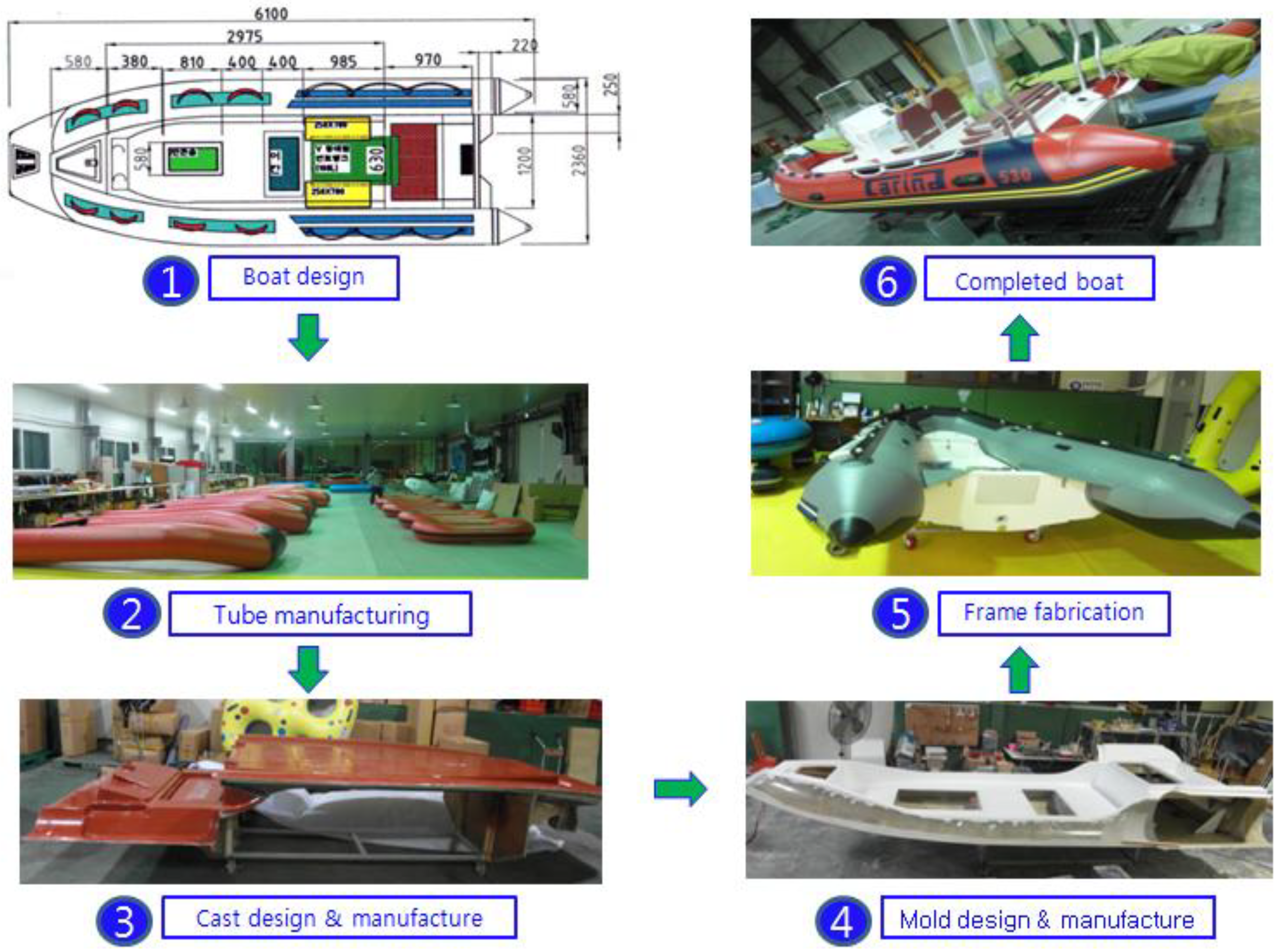
As there are many processes of manual production of underwater boats, it is necessary to use a standardized production system in relation to safety. Therefore, in the production of the water surface attachment device, it is possible to manufacture a safe boat through the integration of the production process with the vacuum infusion technology required for the uniform mixing ratio injection of resin and epoxy [
3].
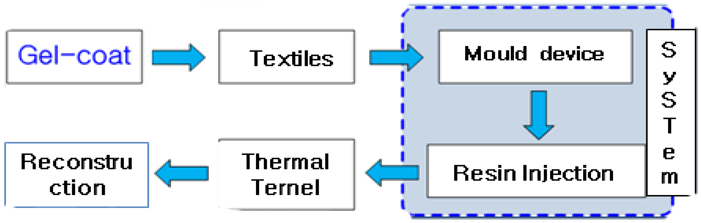
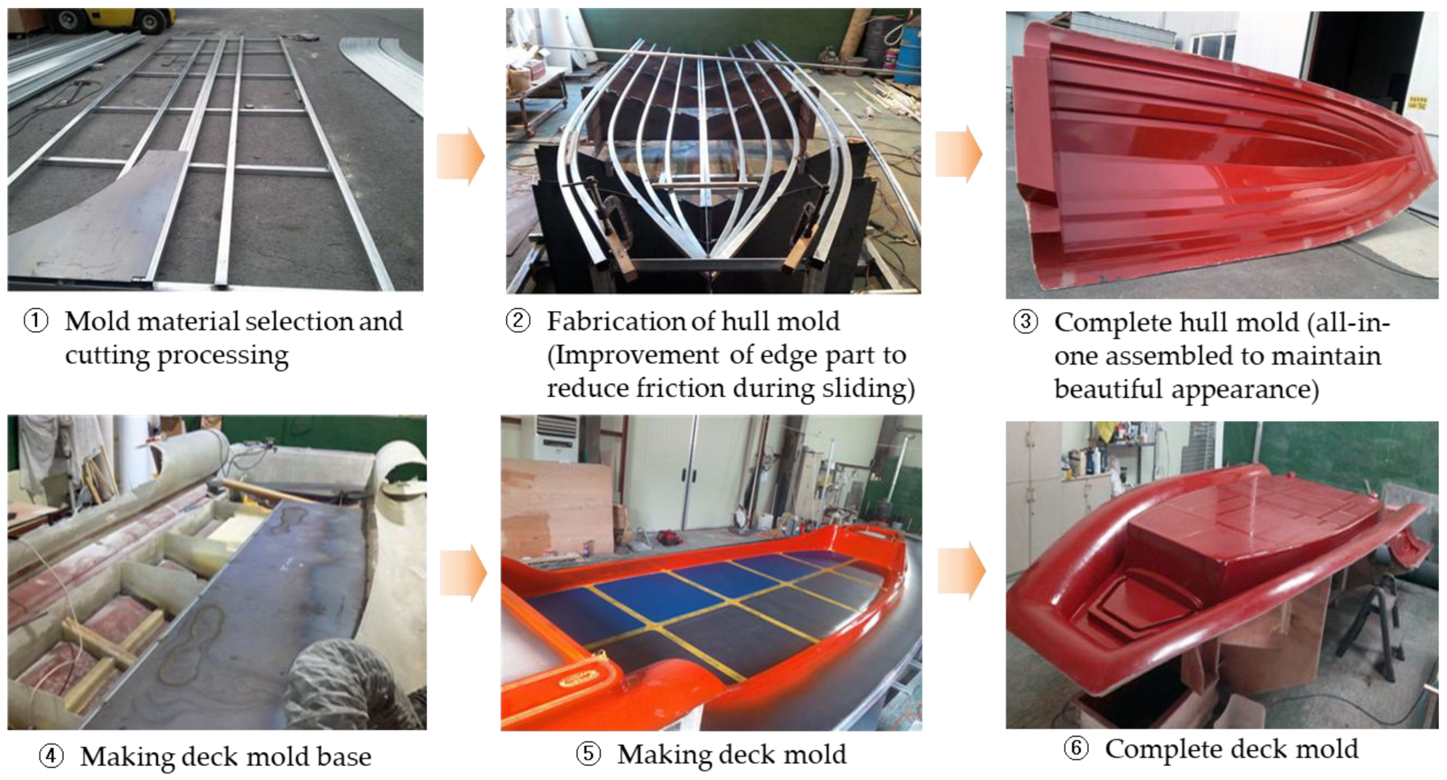
Figure 1 shows the production flow of the boat manufacturing process.
Due to the nature of boat work, various types of small-scale production dominate, and the work efficiency of workers and product quality are determined as all processes are carried out manually. In particular, the resin and the curing agent are mixed depending on the manufacturing experience of the worker, and the manually painted paint also affects the worker's health. Therefore, it is difficult to systematically manage quality, and it is difficult to actively cope with defects [
4].
In addition, in the production of boats that produce small amounts of various types, optimal working arrangement is essential for each workplace, and it affects not only production efficiency but also boat performance. Therefore, it is necessary to design a back-room infusion process automation technology to improve the productivity of hull molds and molds [
4].
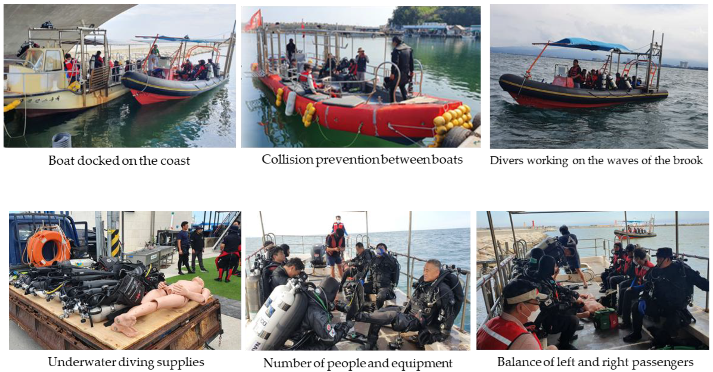
In fact, boats operating at sea level can be used in very poor environments. The worst environment should be considered for the role of boats in mobilizing wind and rain due to severe swells, high flow rates, or rapid environmental changes. Moreover, when a boat is used for special activities such as a coast guard or firefighter operating in the offshore coast, the weight of equipment possessed by divers or related personnel cannot be ignored. Therefore, even if it is designed and developed for a certain number of people on board, it can cause capsized due to the weight of equipment in possession [
5].
Figure 2 shows the boarding status of various active boats, such as coast guards and divers.
In this paper, we develop a vacuum infusion automation technology and process fusion technology to improve boat stability and quality. Using a potential flow algorithm, we can use the potential flow algorithm to determine the amount of flotation generated on the hull. Calculate it and consider it as an additional buoyancy and assess it with hull weight and estimate the constant posture using the form. Resin and hardener are adsorbed inside the hull and deck in a very short time by vacuum at a standardized mixing ratio, and problems such as strength increase and post-deformation are solved.
At this time, by accurately controlling conditions such as the mixing ratio of the resin and curing agent to find optimal conditions for drying and securing rigidity of the boat, model-specific information analysis and optimization information on working conditions such as resin flow rates and resin flowcharts by time is converted into a DB to improve quality such as durability.
2. Vacuum infusion method and molding design
The streamlined design of the waterfront contact, the injection of the balance of the mixture inside the instrument, and the balance of the left and right weights must be constant to be safe during high-speed driving. In high-speed driving, the imbalance mechanism is linked to a direct accident in case of a scratch or collision by an underwater obstacle.
2.1. Analysis of 3D liquidity of boats
The key to the development of built-in extended mold design and molding technology is to secure durability through reinforcement of the lattice at the back of the mold. Automatic bonding using a coupling device, high gloss maintenance through vinyl ester gel coating, and boat design optimization based on 3D flow analysis play an important role in standardization and stable production of the system by reducing multiple work processes [
6,
7,
8,
9].
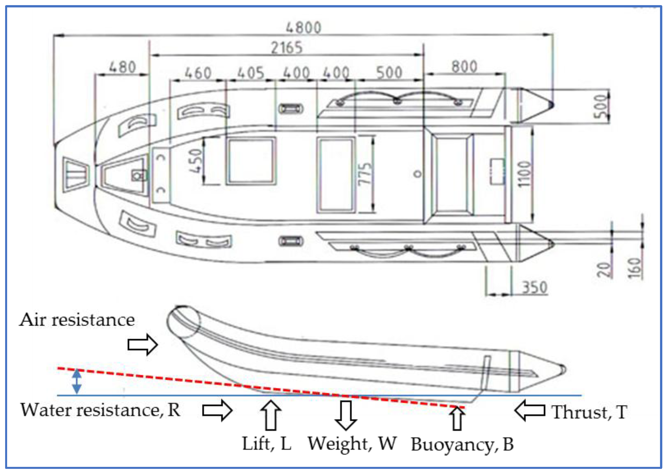
Figure 3 shows design examples of the total length, total width, tube thickness 500 m/m, compartment water 4 ea, loading load 1150 kg, 8 people on board, propulsion engine 50-70 HP, and weight 185 kg [
4].
During the suspension, the static buoyancy force (B) and the dynamic force, the flotation force (L), are in equilibrium with the hull weight, and in this process, the thrust force (T) by the thruster and the moment by the resistance (R) of the hull addition are added to determine the suspension posture. These forces and moments have an equilibrium relationship with the forward direction, the vertical direction, and the moment as shown in the following equation [
6].
Here, t is the thrust reduction coefficient, and LCG′, LCB′, LCL′, and LCT′ are respectively. The distance between the force and the center of the moment, θ, has a trim angleC. In the case of a high-speed runway, most of the weight of the hull is due to the flotation force. It is supported, and the hull weight, buoyancy, and flotation force are each centered in the port position. In the process of equilibrium with, it appears in the form of trim and flotation.
2.2. Air boat mold design and implementation
The key to the design and molding of the built-in extended mold of the boat is to secure durability through reinforcement of the lattice at the back of the mold. The manufacture of boat equipment is based on automatic bonding using a coupling device and 3D flow analysis through vinyl ester gel coating, and design optimization plays an important role in standardizing and stable production of the system by reducing multiple work processes [
7].
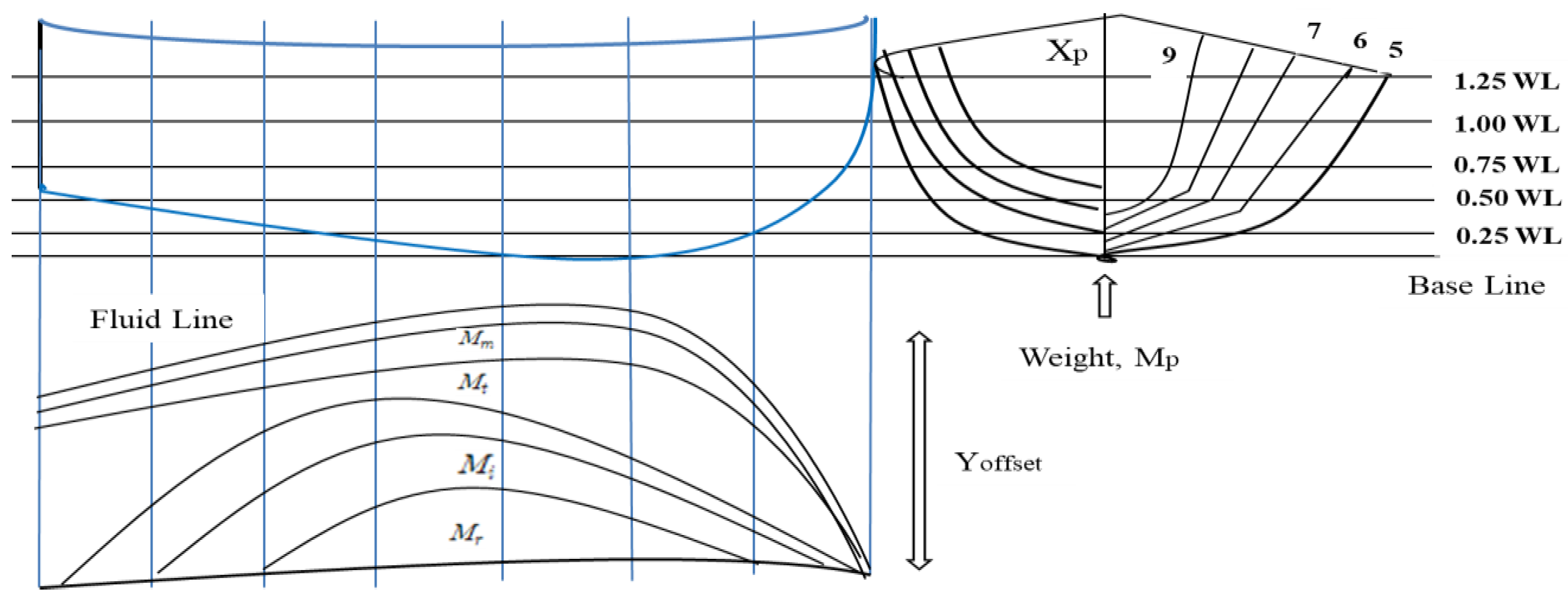
Figure 4 shows the equilibrium and weight-centered 3D flow analysis of the boat. The force moment balance equation for flow analysis is as follows.
In Equation (4),
is the overall center of gravity of the ship,
and
shows the center of gravity variable that is converted from the presented lower hull to the upper body. In Equation (5),
represents the distance of the center of gravity that changes from the lower body to the upper body. Based on these equations (4) and (5), the force and moment balance equation and center of gravity are designed for 3D flow analysis [
4].
2.3. Vacuum infusion process convergence automation system
The development of automation technology for vacuum infusion process fusion automation has the function of automatically adjusting the mixing ratio of the resin and curing agent and automatically adjusting the discharge amount of the mixed resin and curing agent [
4,
7,
9].
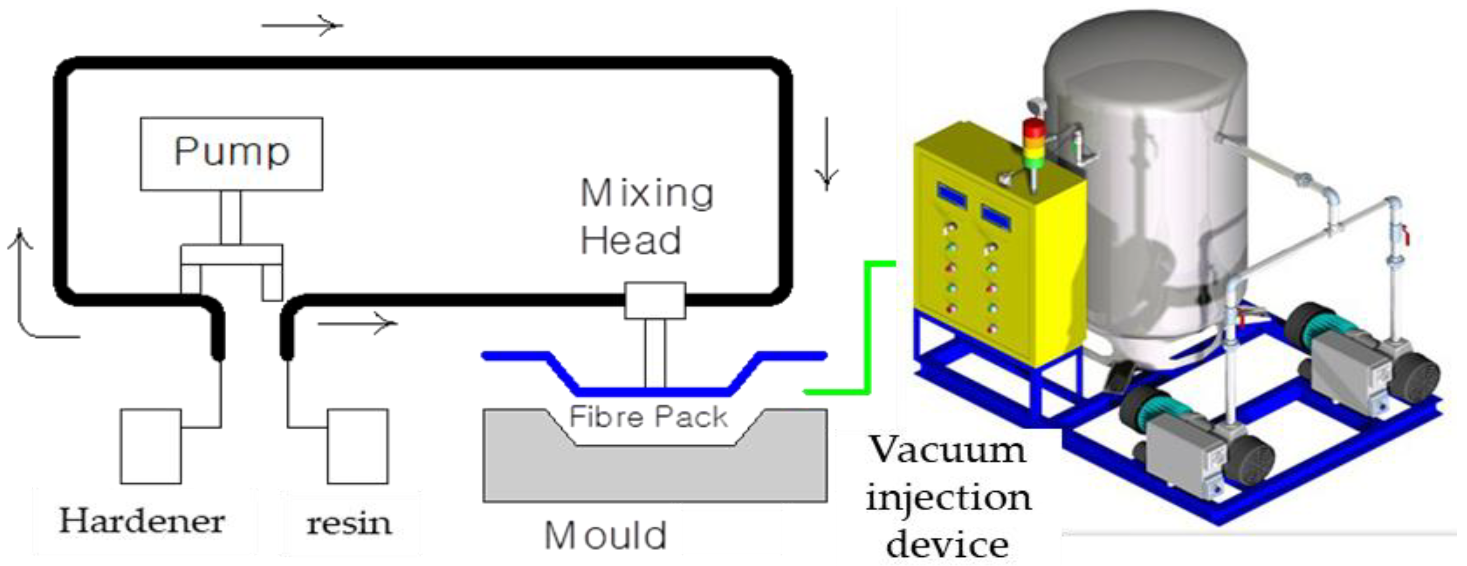
Figure 5 is a converged process of mold device and resin injection vacuum infusion process.
Figure 6 is a layout of the vacuum infusion wiring diagram for preparing an optimization plan by analyzing information on working conditions such as resin flow rate and resin flow chart by time. The vacuum facility resin injector can efficiently manage the production process with a small number of workers in multiple workplaces.
The development of the fiber lamination and vacuum resin injector in
Figure 6 enables the combination of RTM and infusion, which can perform the adjustment function after calculating the discharge amount per desired time [
4]. At this time, Equation (6), which is the curing agent mixing method Q, is a variable equation according to the mixing ratio of 0.5 to 4%, and Equation (7),
represents the impregnation rate.
Here, Q represents the resin flow ratio, fabric permeability, flow longitudinal section, viscosity, silver length, and pressure difference.
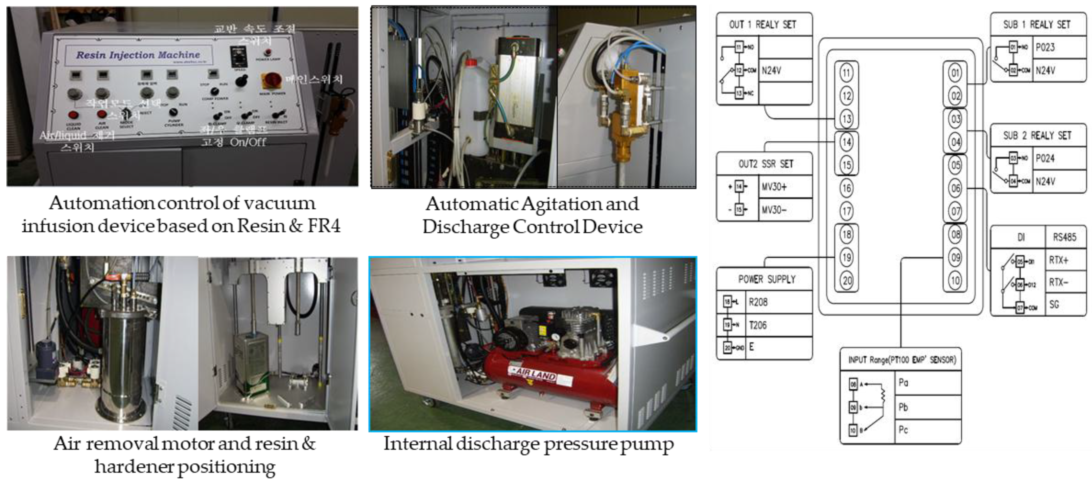
Figure 7 shows the PLC algorithm of the automated interlocking circuit control unit. When power is input, it is controlled by each relay through the SSR output. At this time, RS485 manages data in parallel with a PC as necessary, and each relay part performs the function of mixing a resin material, and it is connected to a nozzle and used for molding. In improving the process of mold design and manufacturing process, it is possible to standardize and optimize the design process through CAE/CAD design, and by identifying quality problems that appear during the manufacturing process, quality and productivity can be improved through the usefulness of the verified data [
4,
10].
The vacuum infusion automation device consists of an instrument panel, a stirring device and a discharge amount adjustment device, an air removal motor, a resin hardener position calibration, and an internal discharge pressure pump.
3. Manufacturing convergence of air instrument and boat floor molding
3.1. Air instrument implementation technology
When manufacturing the air appliance in
Figure 1, all processes are carried out manually, so the work efficiency and product quality are determined by the operator, and it is very difficult to actively cope with defects in case of occurrence [
4].
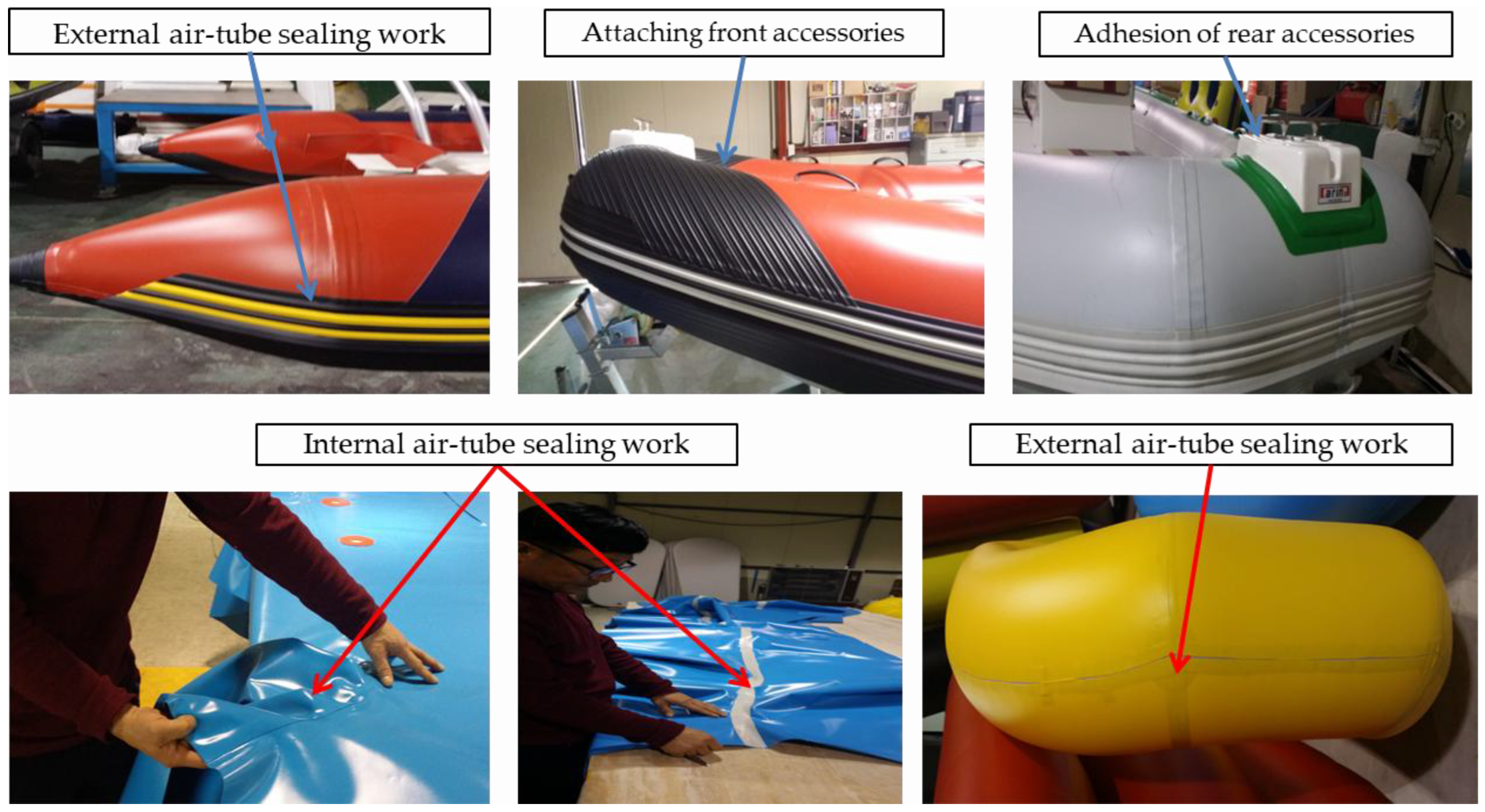
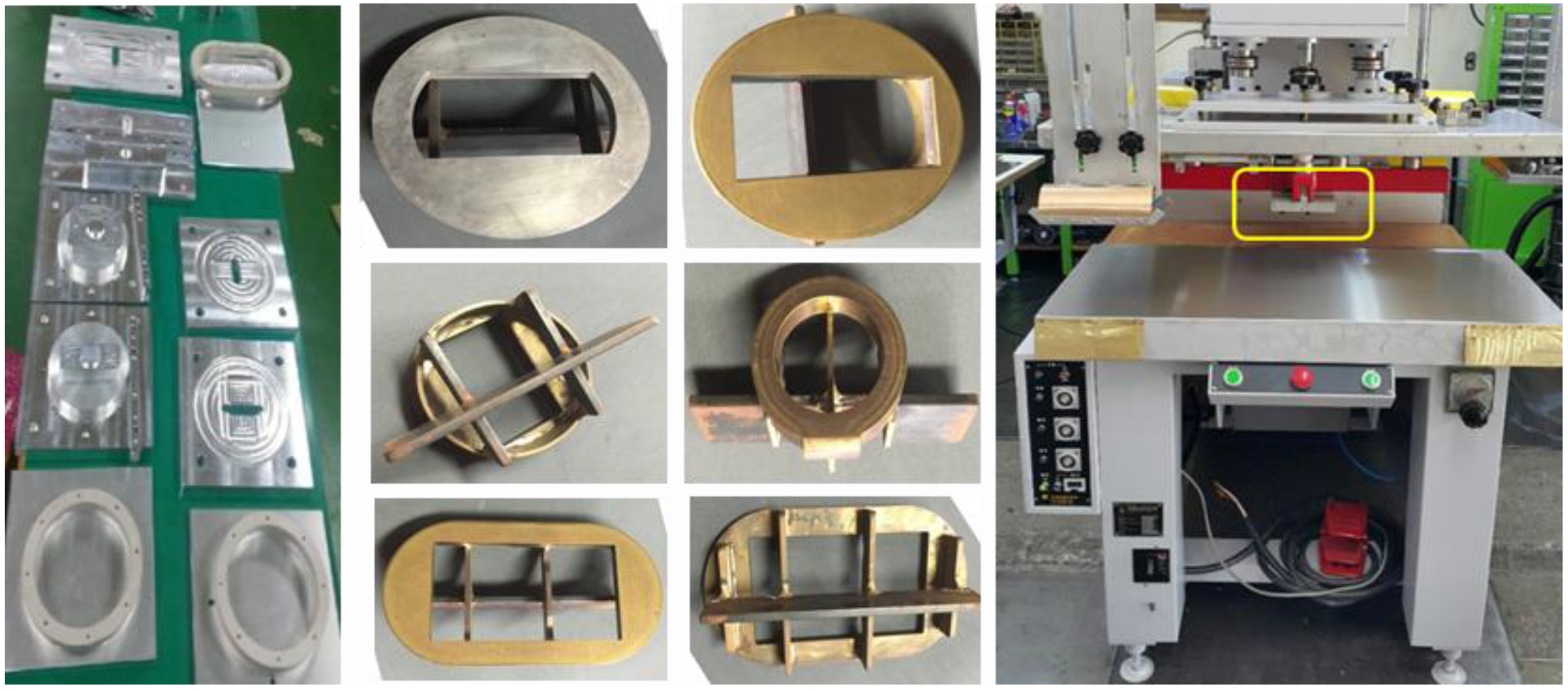
Figure 8 shows examples of manual processes such as air tubing and accessories.
Table 1 shows the main facilities, daily working hours, and weight used for each unit operation.
In the main process of
Table 1, risk factors arise from improper posture and repetitive work. In particular, there are human threats for each process according to the production experience of workers, and systematic quality management is required. In the production of small-scale production of various types of boats, production efficiency is linked to an increase in production cost. Therefore, a burden appears on the musculoskeletal system according to the manual operation of accessories and wide joints according to the efficient arrangement of workers at each workplace.
Table 2 shows a task check table that is a burden on the musculoskeletal system.
According to the investigation of working conditions according to the production of accessories and width joint manual work, mold accessories that are repeated for more than 4 hours a day when manufacturing a diaphragm, and repetitive work using arms, elbows and waist according to width joint manual work are closely related to workers' safety and production quality. In addition, when air-tube leaks and defects occur, it is a fatal cause of productivity decline.
Table 3 suggests improvements from the problems of this process. Currently, all of the width joints and cosmetic tapping processes of air-tube are manually carried out, causing falls, damage, or leaks. Accordingly, standardization and work speed must be accelerated, and adhesion that does not fall off should be maintained once attached. Mechanization and automation are required to minimize human body impact due to the smell of bonding adhesion by checking the location of the air-tube accessory and bonding it at once, and the accessory and mold can be integrated accurately. In particular, as bonding work increases as production increases, it is necessary to develop a convergence process capable of improving productivity and reducing cost to prevent peeling. According to the working conditions of accessory production and width joint manual work, mold accessory production work repeated for more than 4 hours a day during diaphragm production, and repetitive work using arms, elbows and waist according to width joint manual work are closely related to the safety and production quality of workers. Therefore, in the event of an air-tube leak or defect in
Figure 8, the reliability of the boat decreases, and it is a fatal cause for safety [
13,
14,
15].
Table 3 proposes a method for reliability and safety of the boat from these process problems.
3.2. Manufacturing convergence of boat floor molding
The molding is constructed in consideration of the variable that changes the center of gravity in the process of converting the entire center of gravity of the ship and the lower hull to the upper body [
16,
17,
18]. At this time, the force and moment balance and center of gravity for 3D flow analysis are designed according to the center of gravity and distance that changes from the lower body to the upper body as shown in Equation (2).
Figure 9 shows the manufacturing process of the boat floor molding based on the flow analysis.
It is important to develop specimens in order to produce elemental elements of the boat. In particular, various types of specimens are data based depending on the boat part.
Figure 10 shows various specimen cases and hot-sesling system. Hot-sealing with excellent adhesive performance is manufactured and used in the width joint or taping process of air-tube to prevent damage or leakage [
4]. In particular, it is necessary to maintain a high degree of adhesion, check the exact location of air-tube accessories, and minimize human body impact due to harmful odors generated during bonding. In addition, as bonding work increases, peeling prevention plays an important role in the production efficiency, reliability, and safety of boats.
4. Experimental results
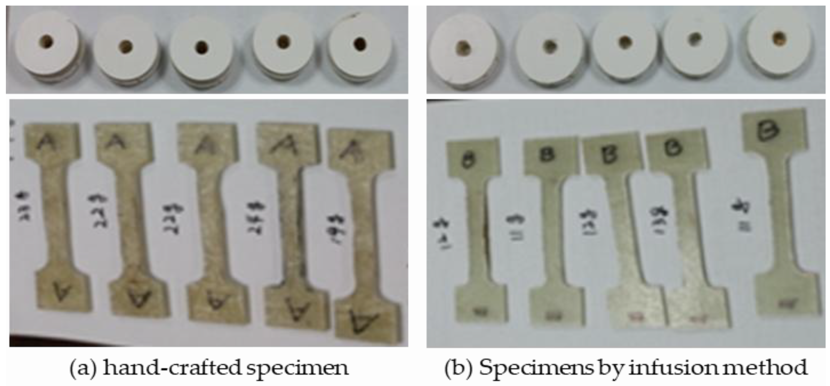
Figure 11 is a sample of 5 samples, (a) hand-crafted specimen, and (b) specimens by vacuum infusion device. Pieces made by manual and bequem infusion method can have a ratio of tensile and compressive strength. Despite the specimens of the same size, the weight of the specimen made of bequem infusion is about 48% lighter on average than that of the specimen made by hand, and the amount of resin used is smaller.
By comparing the tensile strength test of manual and vacuum infusion by the Korea Institute for Construction and Living Environment, it is possible to improve product quality through automation in process automation technology.
The introduction of the database automatically adjusts the precise mixing ratio of resin and curing agent, the discharge amount of resin and curing agent mixture using sensors and drivers, and guarantees the performance of vacuum maintenance work through tensile strength and compressive strength of hull and deck manufactured according to the mixing ratio of resin and curing agent.
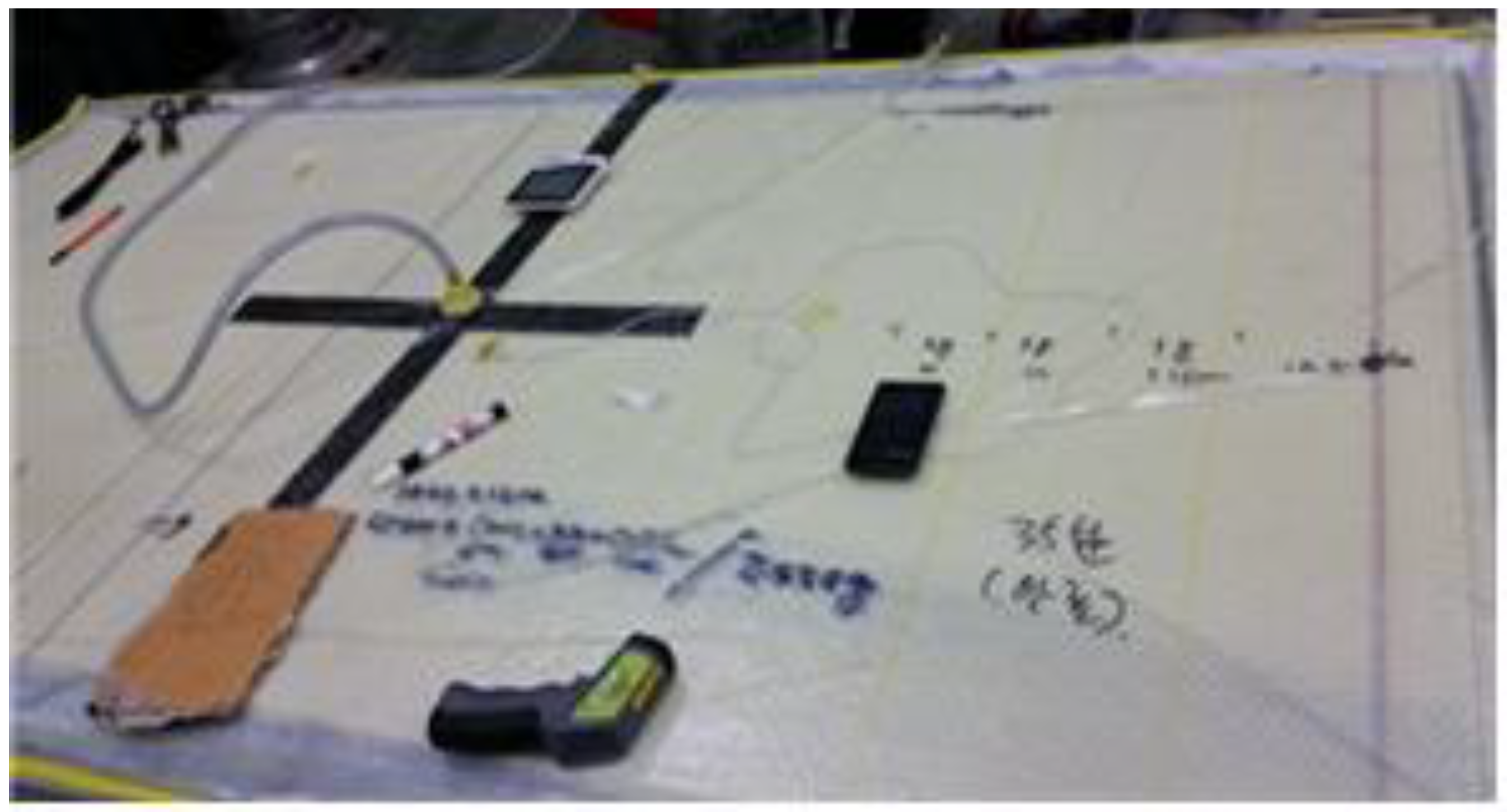
Figure 12 shows the process of specimen production and weight-centered analysis during vacuum infusion work for database construction and performance analysis of specimens [
4,
7,
8].
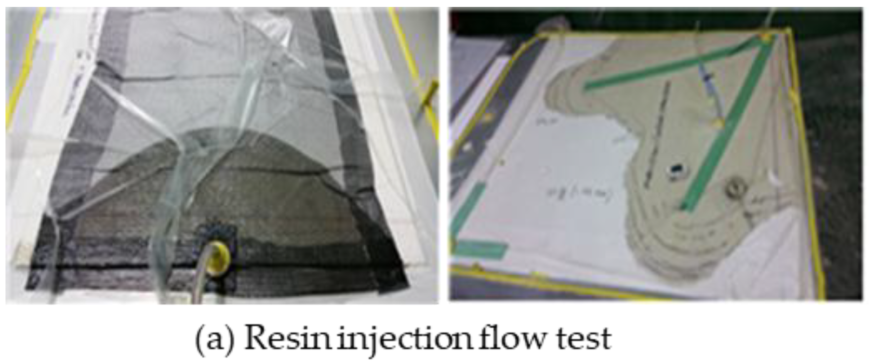
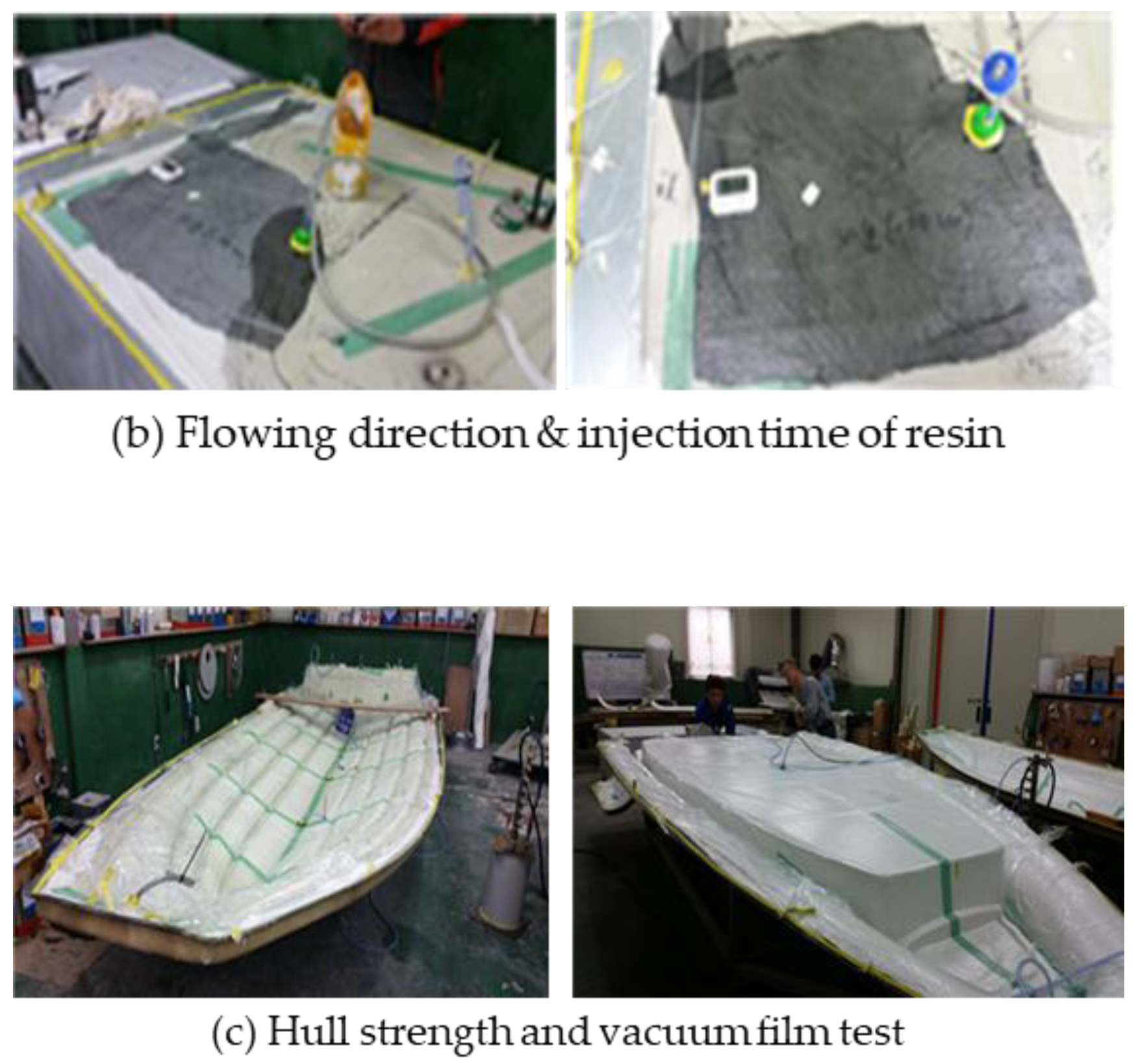
Figure 13 shows a performance evaluation test for manufactured process device using the vacuum infusion method, and showing (a) resin injection flow test, (b) resin flow direction and injection time test, (c) hull strength and vacuum film test.
Table 4 shows comparison values for the thickness and weight of specimens manufactured by manual and vacuum infusion methods shown in Fig. 10 and Fig. 11 as data.
In the study of
Table 4, the difference in thickness and weight was almost negligible, which means that the resin content is constant. Therefore, when comparing the hull, deck weight, and resin consumption through the infusion method, it is possible to reduce by more than 40% compared to the case of manual work. Compared to manual work in the entire boat, it is possible to expect a reduction in the hull weight as well as a reduction in the resin of 50% or more during the vacuum infusion method. As a result, the decrease in the total weight of the boat can also be expected to increase fuel efficiency.
Table 5 compares the tensile and compressive strength of vacuum infusion and hand-made composite materials. A database of physical properties was established based on the test and certification of the nationally accredited agency (Korea Institute for Construction and Environmental Testing). Here, the tensile strength of the specimen produced by the Becum infusion method is only 30% thick, but the tensile strength is superior to that of the specimen made manually.
In
Table 5, it can be seen that in the case of specimens having the same thickness, the compressive strength is also much better made of the Becum infusion method. In addition, analysis conditions for analyzing the thickness, weight, and resin flow rate according to the mat lamination and resin type were presented in the DB. When the number of stacks was the same, both thickness and weight of the Becum infusion were smaller than those of the manual case, which means that the proportion of the resin absorbed by the products made by the Becum infusion is small.
Table 6 shows the database for analyzing thickness, weight, and resin flow rate (min/cm) according to the mat lamination and resin type. As confirmed, when the number of stacks was the same, both thickness and weight of the becum infusion were smaller than those of the manual operation, which means that the proportion of the resin absorbed by the products worked with the becum infusion is small.
Table 7 compare the results of changes in thickness, weight, and flow rate of products manufactured according to conditions, and it can be confirmed that the Becum Infusion method has advantages such as thickness and weight reduction effect, reduction of working time, and uniformity of molding production
5. Conclusion
In this study, a vacuum infusion method was presented and the performance of manual work was compared through boat design and manufacturing. In particular, in order to differentiate the samples that can build the safety and reliability of the boat, a database was constructed through process fusion during the manufacturing process.
For the three-dimensional flow analysis of force and moment, the boat was designed in consideration of the variable that changes the center of gravity in the process of converting the entire center of gravity of the lower hull to the upper body through balance and center of gravity. At this time, it shows the process of manufacturing a boat floor molded product based on flow analysis according to the center of gravity and distance that changes from the lower body to the upper body.
As a result of comparing the tensile strength and compressive strength of the vacuum injection method and the handmade composite material through specimen manufacturing, it was confirmed that the tensile strength of the specimen manufactured by the vacuum injection method was only about 30% thick compared to the handmade specimen, but the tensile strength was more than 50%. In addition, it can be confirmed that the working time is shortened and the possibility of uniformly manufacturing molded products is confirmed, in addition to the effect of reducing thickness and weight.
This study can secure the safety and reliability of boats according to the activation of the leisure industry, and prevent possible safety accidents as the center of an unevenly designed ship changes during the high-speed process. In addition, an infusion method was proposed to minimize damage that may occur during underwater rocks or collisions.
References
- Korean Society for Research and Research. A Study on the Status of Leisure Sports Industry 2023, 24, 33–79. [CrossRef]
- Available online: https://www.sports.re.kr/front/board/bs/boardList.do?board_seq=72&menu_seq=862.
- S. W. Lee; S. G. Kim; J. H. Lee; J. W. Hong; Y. J. Lee; H. A Study on Marine Tourism Policies to Upgrade the Marine and Pleasure Boat Industry of Korea Korea Maritime Fisheries Development Institute. 2008.
- D. H. Yoon; S. H. Kim; H. G. Min, Development of Boat Aerostat for the Safety Strengthen based on the Manufacture Convergence. Korean Journal of Safety Culture 2020, 25–32.
- J. H. Yoon; D. H. Yoon, Implementation of a GAS Injection Type Prefabricated Lifting Device for Underwater Rescue Based on Location Tracking. ASTES 2023, 8, 78–86. [CrossRef]
- G, H, Oh; J. H. Yoo, Numerical Prediction of Running Attitude and Resistance of Planing Craft. 2013, 50, 95–103.
- Dupon-Mitsi Poly-Chemical, Resin Modeling Device, Resin Modeling Method, and Resin Container, 2011. Patent No. 101059936.
- U. Gokai, Laminate Modeling Device and Method, Japan, 2010; PCT/JP2010/058649.
- D. N. Kabusikigaisha, Process and Apparatus for Effecting Injection -molded in Foil Decoration, 2002; Patent, No.100350582.
- J. H. Yoon; D. H. Yoon, A Human Lifting and Navigation System Based on ICT for Underwater Rescue, ICCAS 2022, BEXCO, Busan, Korea, Nov. 27~Dec. 2022.
- D. H. Yoon, Location Tracking Apparatus and Method in Water Accident or Emergency Situation, 2020; Patents No.10-2020-0142370.
- H. K. Min; D. H. Yoon, et al, Information Transmission System of Lifting Apparatus, 2020; Patents No.10-2020-0127360.
- D. H. Yoon; M. H. Park, Water Accident Emergency Response System and Method Thereof, 2020; Patents 10-2020-0126397.
- D. H. Yoon, Boat Aerostat Production Apparatus and Method for Safety Strengthen Based on Manufacture Convergence, 2020; Patents No.10-2020-01378 78.
- J. H. Yoon, An Underwater Transport System that can Carry Multiple Objects Simultaneously, 2021; patents: No.10-2021-0161064.
- Korean Society for Research and Research Science and Technology, System Assessment and Validation for Emergency Responders (SAVER), 2021; U.S. Department of Homeland Security.
- Central Maritime Safety Tribuna, Announcement of Maritime Accident Statistics in 2021.
- H. K. Min; N. H. Seong; et al, Development of ICT-based Human Body Lifting System for Underwater Structures, 2021, Technical Report, Ministry of SME s and Startups.
Figure 1.
Production flow of boat.
Figure 1.
Production flow of boat.
Figure 2.
Boarding status of various active boats.
Figure 2.
Boarding status of various active boats.
Figure 3.
Force diagram in running boat condition.
Figure 3.
Force diagram in running boat condition.
Figure 4.
Equilibrium and weight-centered 3D flow analysis of the boat.
Figure 4.
Equilibrium and weight-centered 3D flow analysis of the boat.
Figure 5.
Process convergence flow diagram of vacuum infusion.
Figure 5.
Process convergence flow diagram of vacuum infusion.
Figure 6.
Layout of the vacuum infusion wiring diagram.
Figure 6.
Layout of the vacuum infusion wiring diagram.
Figure 7.
PLC algorithm of the automated interlocking circuit control unit.
Figure 7.
PLC algorithm of the automated interlocking circuit control unit.
Figure 8.
Examples of manual processes such as air tubing and accessories.
Figure 8.
Examples of manual processes such as air tubing and accessories.
Figure 9.
Manufacturing process of the floor molding.
Figure 9.
Manufacturing process of the floor molding.
Figure 10.
Various specimen cases and hot-sealing system.
Figure 10.
Various specimen cases and hot-sealing system.
Figure 11.
Sample of 5 samples.
Figure 11.
Sample of 5 samples.
Figure 12.
Process of specimen & weight-centered analysis.
Figure 12.
Process of specimen & weight-centered analysis.
Figure 13.
Performance evaluation test for manufactured device.
Figure 13.
Performance evaluation test for manufactured device.
Table 1.
Unit action details.
Table 1.
Unit action details.
| Process name |
Unit work |
Major facilities |
Time/Day |
Unit weight |
| 1 |
Tailoring work |
Drawing a fabric pattern |
Hand cutting machine |
More than 4 hours |
20 Kg |
| Bottom drawing foundation |
- |
| 2 |
Making and working with accessories |
Making Accessory Membrane |
Manual operation |
More than 4 hours |
3 Kg |
| Fabric adhesion |
3 Kg |
| 3 |
Width joint |
Fabric piecxe adhesion |
Manual operation |
More than 4 hours |
3 Kg |
| 4 |
Addition width |
Fabric cylindrical bonding |
Drier, sharp knife, Scissors |
More than 4 hours |
5 Kg |
| Press to trim the adhesive area |
- |
| 5 |
Make-up tape |
Make-up tape gluing |
Manual operation |
More than 4 hours |
5 Kg |
| Trim the adhesive area |
- |
| 6 |
Bottom adhesion |
Boat post adhesion |
Cutter, Knife |
More than 4 hours |
5 Kg |
| Boat bottom adhesion |
- |
| 7 |
Accesory adhesion |
Rubbing & bottom adhesion |
Manual operation |
More than 4 hours |
5 Kg |
| Adhesion of accessories |
- |
| 8 |
Packaging |
Boat-folding box |
Bending, Packaging, Boxing |
More than 4 hours |
25 Kg |
| Place movement after bending |
25 Kg |
Table 2.
Task check that is a burden on the musculoskeletal system.
Table 2.
Task check that is a burden on the musculoskeletal system.
| Sortation |
Exposure time/day |
Body parts |
Working posture content |
Weight/exposue frequency |
| Work 1 |
More than 4 hours |
Hand, wrist, arm, shoulder |
Data input |
Frequency |
| Work 2 |
More than 2 hours |
Wrist, elbow, shoulder |
Repeat the same action |
| Work 3 |
More than 2 hours |
Arm, shoulder |
Task in which the elbow is heard by the body |
| Work 4 |
More than 2 hours |
Neck, waist |
Bending or twisting without changing posture |
| Work 5 |
More than 2 hours |
Knee, waist |
Squatting knees |
| Work 6 |
More than 2 hours |
Finger |
Finger-grabbing work |
Carrying more than 1 kgCatch more than 2 kg |
| Work 7 |
More than 2 hours |
Hand |
Act of lifting or catching an object |
Lift and hold objects greater than 4.5 kg |
| Work 8 |
More than 2 hours |
Waist |
Work of carrying things |
25 Kg/day at least 10 times |
Table 3.
Proposed method for reliability and safety of the boat.
Table 3.
Proposed method for reliability and safety of the boat.
| No. |
Analysis contents |
Improvments |
| 1 |
Prediction of boat position through 2D flow analysis |
Prediction of boat posture by performing optimized flow analysis through 3D design |
| 2 |
Rely on the operator's skill by hand during the production of Air-Tube |
Standardized automation process from experiential fabrication in tube fabrication |
| 3 |
Boat performance based on the angle of the mold and operator's experience in designing the mold |
Secure the safety and reliability of the boat through the development of the proposed construction method |
| 4 |
Production yield problems and boat performance depend on manual work and affect safety and reliability when making molds |
Contribute to improved production yield, improved boat performance and stability through the development of convergence processes and automation of production lines |
| 5 |
Insufficient production quality control |
PC-based database and monitoring with daily, weekly, and monthly resource management |
Table 4.
Comparison values for the thickness and weight of specimens.
Table 4.
Comparison values for the thickness and weight of specimens.
| Sortation |
Sample 1 |
Sample 2 |
Sample 3 |
Sample 4 |
Sample 5 |
Average |
| Manual Process01 |
Thickness (mm) |
11 |
9.2 |
9.5 |
10 |
11 |
10.1 |
| Weight (g) |
11.5 |
12 |
9.6 |
11 |
10 |
10.7 |
| Manual Process02 |
Thickness (mm) |
10.8 |
12 |
9.2 |
10 |
10.5 |
10.5 |
| Weight (g) |
10.9 |
12.1 |
9.6 |
10.2 |
10.6 |
10.6 |
| Vacuum infusion01 |
Thickness (mm) |
6 |
6.2 |
6 |
6 |
6.3 |
6.1 |
| Weight (g) |
5.8 |
6 |
6 |
5.8 |
6.1 |
5.9 |
| Vacuum infusion02 |
Thickness (mm) |
6 |
5.6 |
5.8 |
6 |
5.9 |
5.6 |
| Weight (g) |
5.9 |
5.6 |
5.7 |
6 |
5.9 |
5.8 |
Table 5.
Comparisions of the thick, the tensile and compressive strength.
Table 5.
Comparisions of the thick, the tensile and compressive strength.
| Sortation |
Sample 1 |
Sample 2 |
Sample 3 |
Sample 4 |
Sample 5 |
Average |
| Manual |
Thickness (mm) |
6.7 |
6.8 |
6.6 |
6.7 |
6.7 |
6.7 |
| Strengthen power |
Ave. 18.46 (181 MPa) |
| Depression power |
Ave. 20.40 (200 MPa) |
| Vacuum infusion |
Thickness (mm) |
2.4 |
2.2 |
2.3 |
2.3 |
2.3 |
2.3 |
| Strengthen power |
Ave. 27.44 (269 MPa) |
| Depression power |
Temp. value (Thickness 6.7mm) - Ave. 32.68 Real value (Thickness 2.3mm) - Ave. 11.22
|
Table 6.
Database for analyzing thickness, weight, and resin flow rate (min/cm).
Table 6.
Database for analyzing thickness, weight, and resin flow rate (min/cm).
| No |
Stacking method |
Resin |
Tempered glass fiber |
Number of stacks and order |
Thickness (mm) |
Weight (cm/g) |
Flow rate
|
Operation mash |
| 01 |
Manual |
G-713BT |
M450, ROVING570 |
M. M. Rx2 (six sheets) |
4.9 |
5.7 |
- |
|
| 02 |
FH-123NHL |
4.9 |
5.9 |
- |
|
| 03 |
UV-R1 |
4.9 |
5.6 |
- |
|
| 04 |
Infusion-01 |
G-713BT |
2.63 |
2.5 |
0.43 |
PartDistribution |
| 05 |
FH-123NHL |
2.61 |
2.3 |
0.42 |
| 06 |
UV-R1 |
2.6 |
2.1 |
0.46 |
| 07 |
Infusion-02 |
G-713BT |
M450, L T600, DB400, COER, DBL600 |
M, LT, DB, CO, DBL ( five sheets) |
6.1 |
5.94 |
0.27 |
| 08 |
FH-123NHL |
6.0 |
5.96 |
0.3 |
| 09 |
UV-R1 |
5.8 |
5.65 |
0.31 |
| 10 |
G-713BT |
6.1 |
6 |
0.7 |
entireDistribution |
| 11 |
FH-123NHL |
6.15 |
5.9 |
0.75 |
| 12 |
UV-R1 |
6 |
5.8 |
0.78 |
Table 7.
Comparision of the results of changes in thickness, weight, and flow rate of products.
Table 7.
Comparision of the results of changes in thickness, weight, and flow rate of products.
| No |
Terms |
Manual |
Vacuum |
Note |
| 1 |
Resin weight |
160 kg |
80 kg |
50% (⤓) |
| 2 |
Glass fiber |
80 kg |
60 kg |
25% (⤓) |
| 3 |
Ship weight |
240 kg |
140 kg |
42% (⤓) |
| 4 |
Manufacture |
10 |
8 |
20% (⤓) |
| 5 |
Intensity |
181 MPa |
269 MPa |
49% (⤒) |
| 6 |
Pressure strengthen |
200 MPa |
320 MPa |
60% (⤒) |
| 7 |
Ship edge effectiveness |
Minimize the friction area between ship and water for the sharpened ship edge part |
| 8 |
Ship out part |
no bending the line and surface |
| 9 |
Speed up |
About 15 % |
| 10 |
Fuel efficiency |
10% |
| 11 |
Safety |
Safety sense for 7 estimated terms |
|
Disclaimer/Publisher’s Note: The statements, opinions and data contained in all publications are solely those of the individual author(s) and contributor(s) and not of MDPI and/or the editor(s). MDPI and/or the editor(s) disclaim responsibility for any injury to people or property resulting from any ideas, methods, instructions or products referred to in the content. |
© 2025 by the authors. Licensee MDPI, Basel, Switzerland. This article is an open access article distributed under the terms and conditions of the Creative Commons Attribution (CC BY) license (http://creativecommons.org/licenses/by/4.0/).