1. Introduction
The measurement of complex dielectric properties, namely relative permittivity (
) and loss tangent (
), holds increasing significance across diverse applications, ranging from communication devices to military systems. Material characterization is a crucial aspect in microwave RF and electronic devices, where electrical, thermal, and mechanical properties influence overall circuit behavior [
1]. A comprehensive understanding of materials properties operating at microwave frequencies is imperative. Challenges arise when discrepancies in measured values of
using different test methods and variations in electromagnetic (EM) field interactions with the substrate between target applications and testing, leading to unexpected results [
2].
In microwave and millimeter-wave technology, the importance of modern RF substrates depends on two key factors. First, manufacturers must accurately characterize the material parameters of their products to elevate their credibility in the competitive RF market. Second, RF researchers and engineers rely on precise electromagnetic (EM) 2D/3D simulations to design their devices. For these simulations to be effective, it is essential that RF designers have access to accurate, real-world data regarding the dielectric properties of each material, including substrates, thin-films, multi-layer composites, and absorbers, often sourced from manufacturer catalogs.
Substrate manufacturers employ various methods for material characterization at high frequencies. These methods primarily utilize resonant cavities, including coplanar waveguides [
3,
4], transmission lines [
5], and resonant structures such as coaxial line [
6,
7]. However, these existing methods often suffer from limitations, including narrow frequency bands, destructive sample preparation, and difficulty isolating material properties from conductor effects in transmission lines. Our approach overcomes these challenges by offering a wideband, accurate, and adaptable characterization method that effectively mitigates the fringing field and the surface wave effects while maintaining cost efficiency. Although our method does not eliminate the need for destructive sample preparation, it provides a comprehensive solution to the remaining limitations.
Common methods like capacitance meters are unsuitable for high-frequency applications due to the increased parasitic inductance and resistance (RLC effects) of test fixtures and probes when operating beyond 1 GHz. These parasitic components can introduce significant measurement errors, reducing measurement accuracy in RF applications [
8]. The resonant cavity method, on the other hand, is highly accurate but operates within narrow frequency bands. The typical frequency range for a resonant cavity method is usually limited to a specific band determined by the resonator’s design. For example, it is often tuned to frequencies such as 10 GHz, 30 GHz, or higher, depending on the cavity structure, and can only measure a limited range within these frequencies [
9]. Additionally, the method is often destructive, meaning the sample may need to be altered or cut to fit inside the cavity, which is a drawback for materials that are sensitive or costly to prepare.
Methods utilizing transmission lines, without corrected conductor effects, lack precision (up to 10%) in relative permittivity and loss tangent values, particularly at low frequencies [
10]. Planar transmission lines offer improved permittivity estimation for thin film substrates, utilizing either the Full Sheet Resonance (FSR) test method or the Stripline Resonator Method (SRM) [
11]. However, challenges arise as the propagation constant depends on both the dielectric thin film and the metallic conductors in the transmission line, making it difficult to separate the two components. This issue poses challenges in calculating thin film permittivity, rendering these methods inappropriate for characterizing the studied low-k thin film substrates [
12,
13]. In contrast to traditional approaches, this study introduces a refined wideband technique (8–16 GHz) that effectively compensates for fringing field and surface wave effects, which significantly distort measurements on thin-film substrates. Handling these effects is crucial in RF design, as they can introduce capacitance-like behavior, leading to shifts between simulation and measurement data, ultimately affecting circuit performance.
Microwave and RF designers invest significant effort in developing electromagnetic (EM) software to accurately model structures, which results in aligned actual circuit performance with simulations [
13,
14]. However, occasional discrepancies arise between simulated data, based on datasheet permittivity and loss values, and actual measured circuit performance. This gap needs a tuning phase related to the substrate’s dielectric constant and loss tangent, to ensure alignment between simulated and measured results. The complexity increases when dealing with anisotropic substrates, as discussed in [
15]. This paper focuses mainly on characterizing thin-film substrates with thicknesses
, commonly used in high-performance RF circuits.
The developed method leverages resonant structures, inherently designed for wideband characterization in the 8 to 16 GHz range. Although the method is not entirely novel, it refines the use of Multimode antennas and retrosimulation to closely match measurements with simulations. The iterative numerical fitting process used in our approach allows for enhanced precision in extracting and values. This process stands out by ensuring better alignment between simulated and measured data, particularly in dealing with fringing field and surface wave effects. It provides greater accuracy compared to existing methods and reduces operator dependency. A key discovery is that resonant structures on thin substrates (height ) are particularly vulnerable to fringing fields and surface wave effects, leading to significant shifts between simulation and measurement data. These effects mimic capacitance-like behavior, exacerbating mismatches. By iterating through the process, we identified that manufacturer-provided dielectric data often underrepresents these effects, requiring adjustments for accurate RF designs.
To address these discrepancies, we propose a cost-effective method that accounts for the fabrication process variability of the relative permittivity () and the loss tangent () of thin-film substrates. This method can be universally applied across industrial labs, R&D centers, and universities, particularly when designing antennas on low-height substrates. Our technique involves fabricating a Multimode patch antenna and extracting and values through S-parameter measurements and numerical fitting. This refined approach not only handles the fringing field effects but also integrates iterative fitting to ensure that the final dielectric values accurately reflect real-world material behavior. To validate, these refined values were applied in the design of ~9 GHz monomode antennas, yielding excellent alignment between measurements and simulations, proving the reliability and precision of our method.
The proposed method is applied to three low thin-film base materials: RO4350B (2547 m), RO4450F (202 m), and RO4003C (203 m). The design and manufacturing of a random Multimode antenna within a wide frequency band [11 – 19] GHz were carried out for each material. Measurements performed using a Vector Network Analyzer (VNA) included the real and imaginary parts of the input impedance, , as well as the reflection coefficient, . Analyzing input impedance, , rather than relying solely on the reflection coefficient, , provides deeper insights into the EM behavior of the materials. Although this technique requires physically cutting the substrate to create different antennas, making it destructive, its strength lies in its ability to handle thin substrates and account for fringing field effects that cause significant shifts between simulated and measured data.
This paper is structured as follows:
Section 2 explains the technical details of the characterization method.
Section 3 presents experimental results on all three substrate materials and the manufactured patch antennas.
Section 4 provides a discussion of the methodological strengths and limitations of the proposed technique. Finally,
Section 5 concludes the work and offers perspectives and future work on the proposed method.
2. The Characterization Method
The properties of dielectric substrate materials often deviate slightly from the manufacturer’s specified data due to fabrication process variability. The key parameters for antennas and microwave circuit designers are the relative dielectric permittivity and the loss tangent . Even minor variations in these parameters can significantly impact circuit performance, leading to issues such as resonant frequency shifts and impedance mismatches. Consequently, accurate characterization of substrate materials becomes an indispensable phase in the design process, as it directly influences the reliability and efficiency of microwave components.
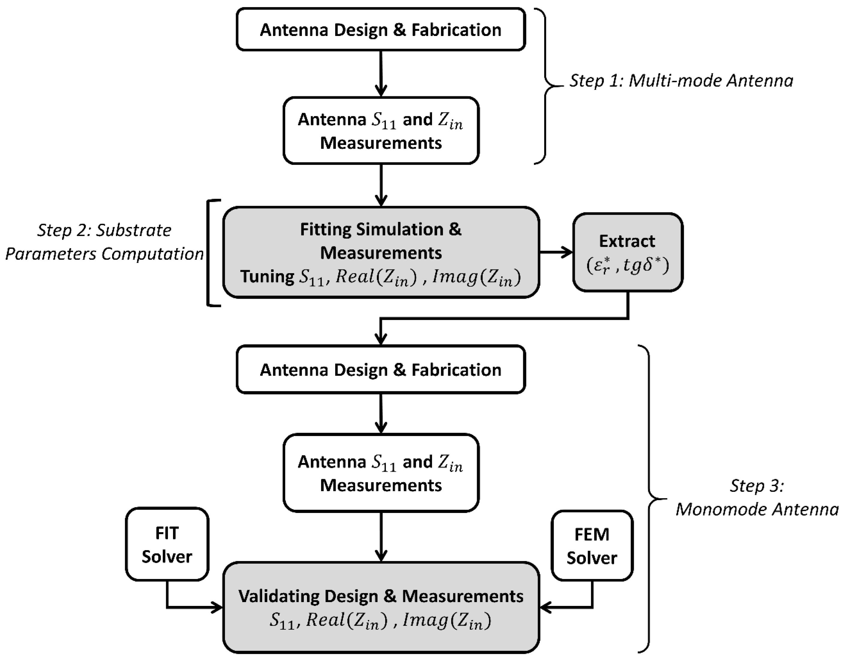
In this study, the characterization method integrates both simulation and experimental measurements, structured into three sequential steps:
Designing, fabricating, and measuring a Multimode patch antenna.
Numerically fitting the measured results through fine-tuning substrate parameters (, ).
Designing, fabricating, and measuring a monomode antenna for validation purposes.
The steps involved in the proposed characterization method are detailed in
Figure 1.
A Multimode antenna is chosen in step 1, to increase the statistical accuracy of the characterization process. These antennas exhibit multiple resonant frequencies ("spikes") within a wideband frequency range, which can provide more data points for fitting during retrosimulation. This abundance of spikes helps reduce error probability, as more resonances allow for a better match between simulations and measurements, statistically lowering the fitting error margin. The use of Multimode antennas not only enhances data density but also helps in identifying potential anomalies in the dielectric material properties.
A monomode antenna is employed in step 3, to validate the fitted parameters. These antennas have a single resonance point at 9 GHz, making it harder to directly fit substrate parameters. However, if the obtained relative permittivity and loss tangent values accurately predict the performance of a monomode antenna (having a single resonant frequency), it strongly confirms the validity of the method. This validation is crucial, as it reinforces the integrity of the initial assumptions regarding the substrate materials, ensuring that the characterization process is not merely an isolated exercise but is linked to practical applications. Essentially, a successful fit of the retrosimulated values to a monomode antenna demonstrates that the technique effectively characterizes the substrate, validating the accuracy of the entire process.
2.1. Step 1: Multimode Antenna Design
The initial phase involves designing and fabricating a Multimode patch antenna tailored to the targeted characterization frequency, typically within the 8 to 16 GHz range. The design process employs advanced electromagnetic (EM) simulation tools to optimize parameters like patch dimensions and feed mechanism, which are critical for achieving the desired operational bandwidth and efficiency. The design form of the antenna includes specific dimensions and geometries that accommodate multiple resonant peaks. While the selection of the number of resonant peaks and their corresponding frequencies may initially appear arbitrary, it is essential for maximizing the antenna’s effectiveness across a broader spectrum of permittivity values. Specifically, opting for a higher number of resonant peaks enhances the frequency diversity, allowing for a more comprehensive characterization of substrate materials.
Subsequently, the modulus of the reflection coefficient
, and the input impedance
are measured using a Vector Network Analyzer (VNA). Discrepancies between the experimental and the simulated results obtained during the design phase arise due to the manufacturing variability of the substrate’s parameters. These variations can be categorized as deterministic errors (systematic deviations due to fabrication tolerances) and stochastic errors (random variations influenced by environmental factors). The impact of these variations is accounted for in the resonant cavity model theory applied to the analysis of patch antennas.
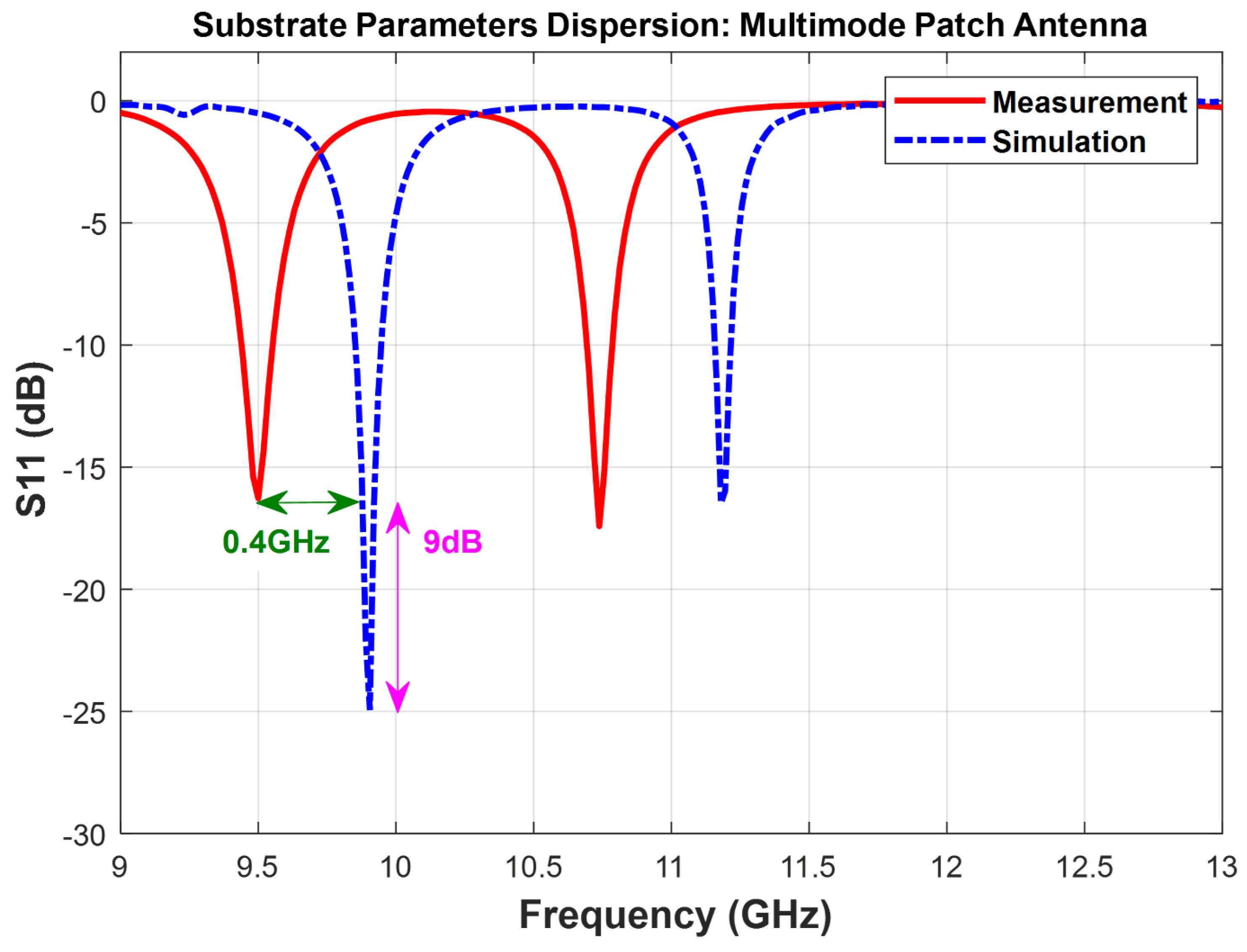
Figure 2 demonstrates that the relative permittivity
influences the resonant frequency
for all modes as described by Equation
1:
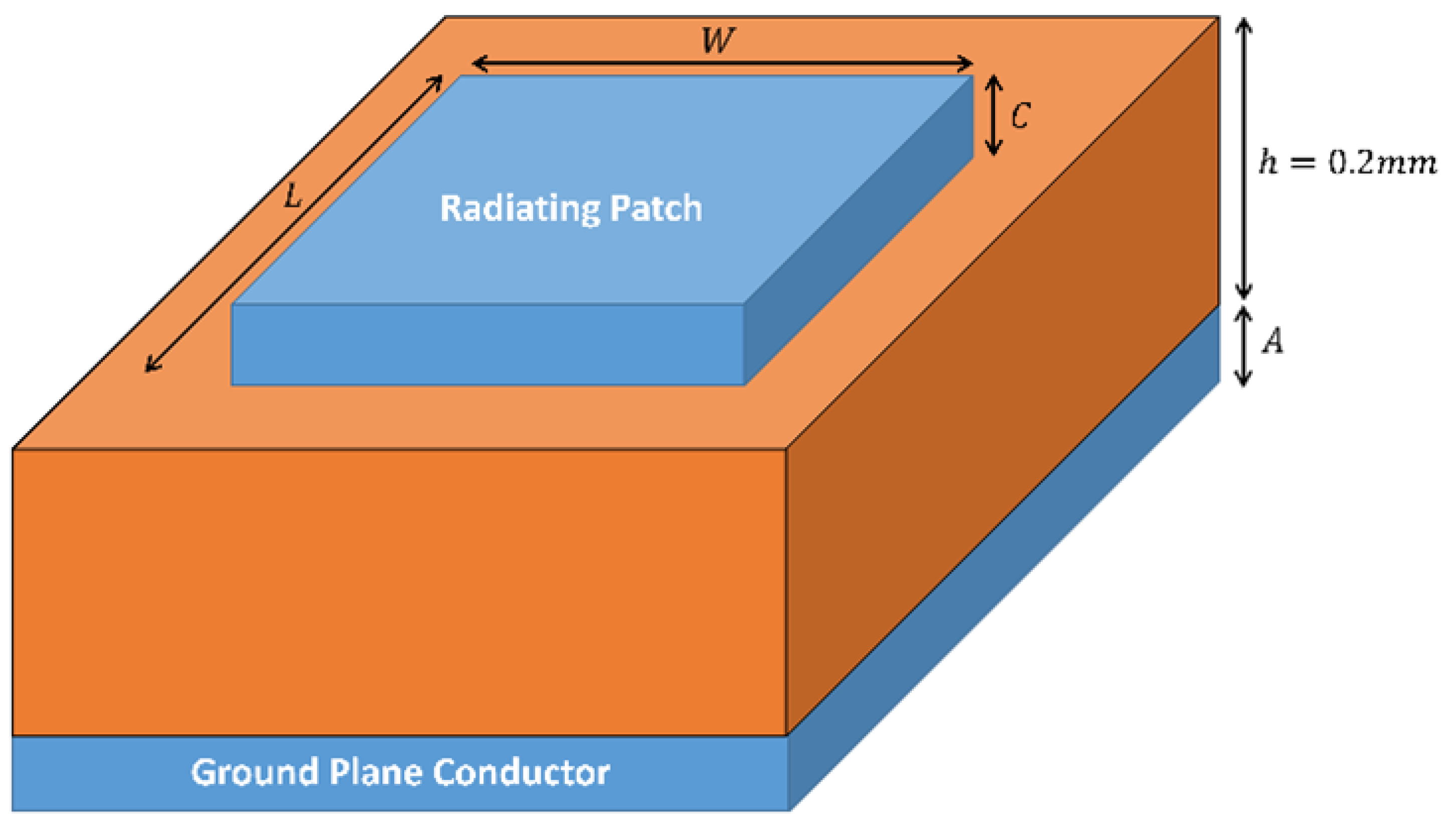
Where L, W and h represent the geometric length and width of the patch antenna’s top conductor and the substrate’s thickness (i.e. height). Additionally, the loss tangent affects the reflection coefficient, with higher values leading to increased impedance mismatch and, consequently, higher values.
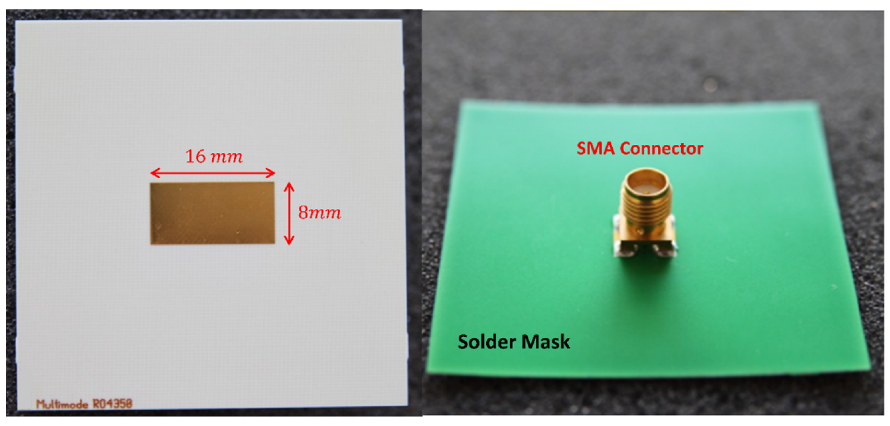
To visualize the impact of these variations, a rectangular Multimode patch antenna measuring 16 mm x 8 mm was designed using specialized EM software, e.g. CST Microwave Studio. The antenna was fabricated on a 0.2 mm-thick RO4003C dielectric substrate.
Figure 2 visually represents the simulation (dotted line) alongside the experimental results following
measurements. Notably, a slight dispersion in
resulted in a resonant frequency shift of approximately 400 MHz in the lower mode. Additionally, a minor
dispersion contributed to an approximated 9 dB difference in
minimum. These shifts underscore the critical role of substrate characterization in ensuring reliable antenna design.
These discrepancies are attributed to the influence of high fringing fields and the material’s surface roughness. Such effects can manifest in various distributed device structures like antennas, filters, and couplers. Given the low substrate height, the modification of field lines by surface roughness induces an increase in capacitance between the designed antenna and the ground plane. This higher capacitance significantly increases the relative permittivity value, highlighting the need for a high relative permittivity value to align with the results observed in
Figure 2.
2.2. Step 2: Substrate Parameters Tuning
To ensure a precise alignment between EM simulations and experimental results, numerical tuning of the substrate’s parameters
and
was carried out. As per Equation (
1), when the physical dimensions (L,W,h) of the fabricated Multimode antenna perfectly match the simulation settings, the variations in resonant frequencies (
) are primarily influenced by the relative permittivity. Therefore, before data fitting, it is crucial to measure the effective dimensions of the antenna, including the top conductor’s geometry and substrate thickness, and incorporate them into the EM software settings. Such errors in dimensions (i.e.
) will induce shifts in the resonant frequencies
precisely due to the influence of
errors. In this work, the antenna’s dimensions were initially measured using a microscope to achieve the necessary accuracy in estimating the physical dimensions. This meticulous measurement process ensures that the tuning process effectively accounts for any discrepancies in the antenna’s geometry and substrate thickness, enhancing the reliability of the subsequent data fitting.
The fitting procedure was enhanced through a series of validation steps, ensuring that the input impedance remained consistent with the expected values throughout the tuning process. Performing complete curve fitting across a broad spectrum of frequencies, such as from 8 to 16 GHz, is computationally demanding due to the time-consuming nature of EM software simulation. This method is not well-suited for the measured data in this work. Instead, a more efficient approach was employed. The fitting process focused on two key parameters: the resonant frequencies of all modes and segments of the curve within 500 MHz around . Notably, the decision to fit only the peak value would not provide a comprehensive representation of the matching quality by itself. Hence, the chosen approach, targeting resonant frequencies and specific portions of the curve, ensures a more nuanced and accurate assessment of the matching quality without the computational burden associated with complete curve fitting.
The tuning process was executed to ensure precision in the characterization of substrate parameters. Initially, the resonant frequency was tuned by adjusting until a relative error between simulation and measurement fell below 0.2%. The impact of on values was temporarily disregarded during this phase.
Once the target value was achieved, the next step involved tuning the loss tangent values to align the amplitude of the simulated and the measured around . This process of sequential adjustment helps in isolating the effects of each parameter, enabling a more precise tuning strategy. This iterative process continued within a reasonable number of steps and simulation time. The partial curve fitting ceased when the mean relative error (MRE) on the target points dropped below 10%, ensuring a correlation exceeding 90%.
Notably, ’s influence on is minimal, facilitating a progressive convergence of the tuning procedure without missing the solution. Achieving MRE < 5% is feasible by extending the number of tuning steps, depending on the specific application’s accuracy requirements. For this work, a 90% correlation between simulation and measurement data of on MHz around was deemed sufficiently accurate, providing a robust foundation for substrate parameter characterization.
In optimizing parameter tuning, a linear fixed-step, while straightforward, proved impractical for this work. The extensive time required by the EM time-domain solver to traverse all predefined sweeping values, especially when the target value deviates significantly from the manufacturer’s data, rendered this method unsuitable. Additionally, employing Newton’s method for root finding faced limitations due to intricate mathematical relations linking to and to within the complex EM simulator.
A more effective approach emerged with the utilization of the secant iterative algorithm. Its application in this work is facilitated by the monotonic behavior exhibited by the functions described in Equation (
1). The secant iterative algorithm provides a practical and efficient means of achieving accurate parameter tuning, overcoming the limitations of direct sweeping and Newton’s method.
The tuning algorithm outlined in Equations (2) to (5) forms a crucial part of this methodology, ensuring precise parameter adjustments for optimal antenna performance. Equation
2 governs the iterative tuning of relative permittivity to match the measured resonant frequency:
is the measured resonant frequency from experimental results and
is the relative permittivity at step k. The iterative process is repeated until 99.8% accuracy is reached (0.2% relative error) as per Equation
3:
Equation
4 defines the iterative tuning of the loss tangent (
) for accurate
curve fitting:
MRE (
) represents the Mean Relative Error between measured and simulated values of
at iteration step
k. The constant value of 5 in Equation
4 represents the ideal reference MRE for optimal loss tangent tuning. This value is determined based on empirical analysis, ensuring that simulated and measured
values exhibit minimal deviation. The iterative process continues until the MRE value drops below 10%, as enforced by Equation
5:
Here, N is the number of points in a bandwidth of ±500 MHz around , and are the linear value of measured and simulated respectively.
Before proceeding to the final step of the characterization process, a comparison is made between measured and simulated curves of the real and imaginary parts of the input impedance (). The target value for Real() is set at 50 to align with the SMA connector used for antenna feeding. A successful fitting ensures that Real() approaches 50 when Imag() is near 0.
2.3. Step 3:Validation by Monomode Antenna
In the final phase dedicated to validating the characterization method, a monomode rectangular patch antenna is designed on a new center frequency (around 8.6 GHz). The critical aspect of this step involves employing the tuned values of relative permittivity and loss tangent obtained from Step-2. Subsequently, the designed monomode antenna undergoes the stages of fabrication, measurement, and a meticulous comparison with the design simulations for thorough verification. This phase serves as a critical test of the entire characterization process, ensuring that the parameters obtained from the Multimode fitting accurately predict the performance of a simpler, single-resonance system.
To enhance the robustness of the validation phase, measurements of the monomode antenna were meticulously compared against simulations conducted on two distinct high-performance 3D EM analysis software. These software solutions employed diverse solving methods, including the time-domain Finite-Integration-Technique (FIT, akin to FDTD) in CST Microwave Studio and the frequency-domain Finite Element Method (FEM) in Keysight ADS. This dual-software comparison ensures a comprehensive assessment of the monomode antenna’s performance, affirming the reliability and accuracy of the proposed characterization method across different simulation platforms and methodologies.
To ensure the accuracy of the validation phase, the resonant frequency shift and partial curve fitting accuracy are meticulously estimated. These estimates are then compared against the identical target criteria utilized in Step-2, demanding below 0.2% relative error on and MRE < 10% on curve. To further enhance the verification process, an additional check is performed on the quality factor of impedance matching in the measured and simulated curves of the monomode antenna.
For the validation to be deemed valid, the method stipulates that the bandwidth over which must exhibit a relative error of 10%. This corresponds to a matching error of 10 MHz on a bandwidth of 100 MHz. serves as one of the indicators of the quality factor of the antenna matching.
A key benefit of the proposed method is its naturally wideband characteristics. Designing Multimode Antennas inherently covers a broad spectrum of frequencies, ensuring that the characterization results remain valid across a wide range of operating microwave frequencies. This widens the applicability and reliability of the method in diverse microwave frequency scenarios.
3. Experimental Results on Substrate Materials
In this study, we undertake an in-depth evaluation of findings from both experimental and computational analyses. Our work leverages a well-established characterization method, applying it in a novel context to three different dielectric substrate materials—RO4350B, RO4450F, and RO4003C—that are widely acknowledged and utilized within the industry. This strategic choice of materials illustrates the method’s versatility and its extensive relevance across various substrates, a facet not extensively explored in previous studies.
We utilize antennas in both Multimode and monomode formats, all conforming to a rectangular patch design integrated with an SMA probe feed system. This setup ensures effective connectivity between the coaxial conductors and the antenna’s radiating patch and ground plane. The antennas were fabricated on substrates with different thicknessess—0.203 mm for RO4003C and RO4450F, and 0.254 mm for RO4350B—to demonstrate the method’s adaptability. For detailed depictions of these antenna designs on their respective substrates, refer to
Figure 3.
Our contribution to the field lies not in introducing a new method but in conducting an in-depth analysis and extending its application to low-height substrates, which remain underexplored in existing literature. A critical aspect of our study is the increased fringing field effects associated with these thin substrates. These effects play a significant role in altering the effective permittivity and loss tangent, impacting both the accuracy of material characterization and the performance of high-frequency applications. By highlighting this interplay, our research underscores the need for careful substrate selection in applications where dielectric properties are sensitive to fringing fields. This refined understanding enhances the collective knowledge of dielectric materials, providing valuable insights for optimizing substrate performance in antenna design and other RF applications.
3.1. Multimode Antenna Design:
In our investigation, we meticulously designed and fabricated a Multimode antenna for each of the selected substrates—RO4350B, RO4450F, and RO4003C—to function across distinct resonant frequency bands. These antennas, with dimensions of
, feature a radiating patch printed on a copper layer with a thickness of 1 oz or approximately
, as visually detailed in
Figure 3.
Figure 4 provides a photographic representation of the Multimode antenna tailored for the RO4350 substrate, equipped with an SMA connector for its feeding mechanism. It is critical to highlight that the remaining two antennas mirror these specifications in dimensions. The simulations carefully integrate the precise specifications of the connectors, including their dimensions and dielectric properties, to ensure accuracy in modeling and analysis.
The electrical properties of the substrate materials under study are detailed in
Table 1, which compiles the typical electrical parameters extracted from the manufacturers’ datasheets [
16]. This comprehensive presentation of data supports a nuanced understanding of the substrate characteristics, facilitating a deeper exploration of their impact on the antenna’s performance across the specified frequency bands.
3.2. Multimode Antenna Results:
In the progressive stage of our research, the characterization process was meticulously carried out on two multimode antennas, specifically those constructed on RO4350B and RO4450F substrates, through detailed measurements and numerical fitting using the CST Microwave Studio time-solver. In parallel, the antenna fabricated on the RO4003C substrate was analyzed using the ADS FEM frequency-solver, showcasing a deliberate methodological diversification. This dual approach was not solely aimed at validating the robustness of our proposed characterization technique across various substrate materials but also at examining its compatibility and efficiency with different solvers and software that are standards within the industry.
Table 2 presents an exhaustive depiction of the simulation settings applied to all the antennas designed for this study. This systematic process underscores our commitment to rigor and precision, emphasizing the adaptability of our characterization method to a spectrum of technological tools and materials. This innovative approach signifies a forward leap in the domain, furnishing a detailed framework that others in the field might adopt or adapt in exploring the vast landscape of antenna design and material characterization.
In the nuanced exploration of our characterization approach, the numerical fitting process across all three substrates was governed by the precise tuning algorithm detailed in Section II.B. This method demonstrated remarkable efficiency, converging within just six iterations—a testament to its efficacy and the streamlined nature of our analytical protocol. The process’s success is further highlighted by meeting the stringent accuracy benchmarks set forth in Equation
3 and Equation
5, with the resultant optimal values for relative permittivity (
and loss tangent
meticulously compiled in
Table 3. The tuning-fitting sequence was deliberately terminated once the Frequency Error (Freq.Error) and Mean Relative Error (MRE) dipped below the critical thresholds of 0.2% and 10%, respectively.
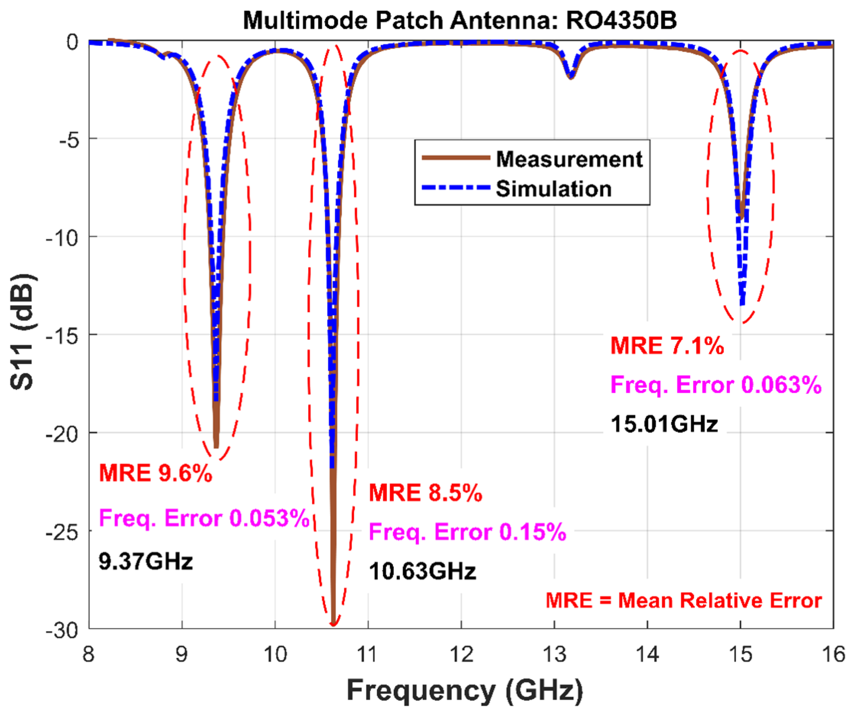
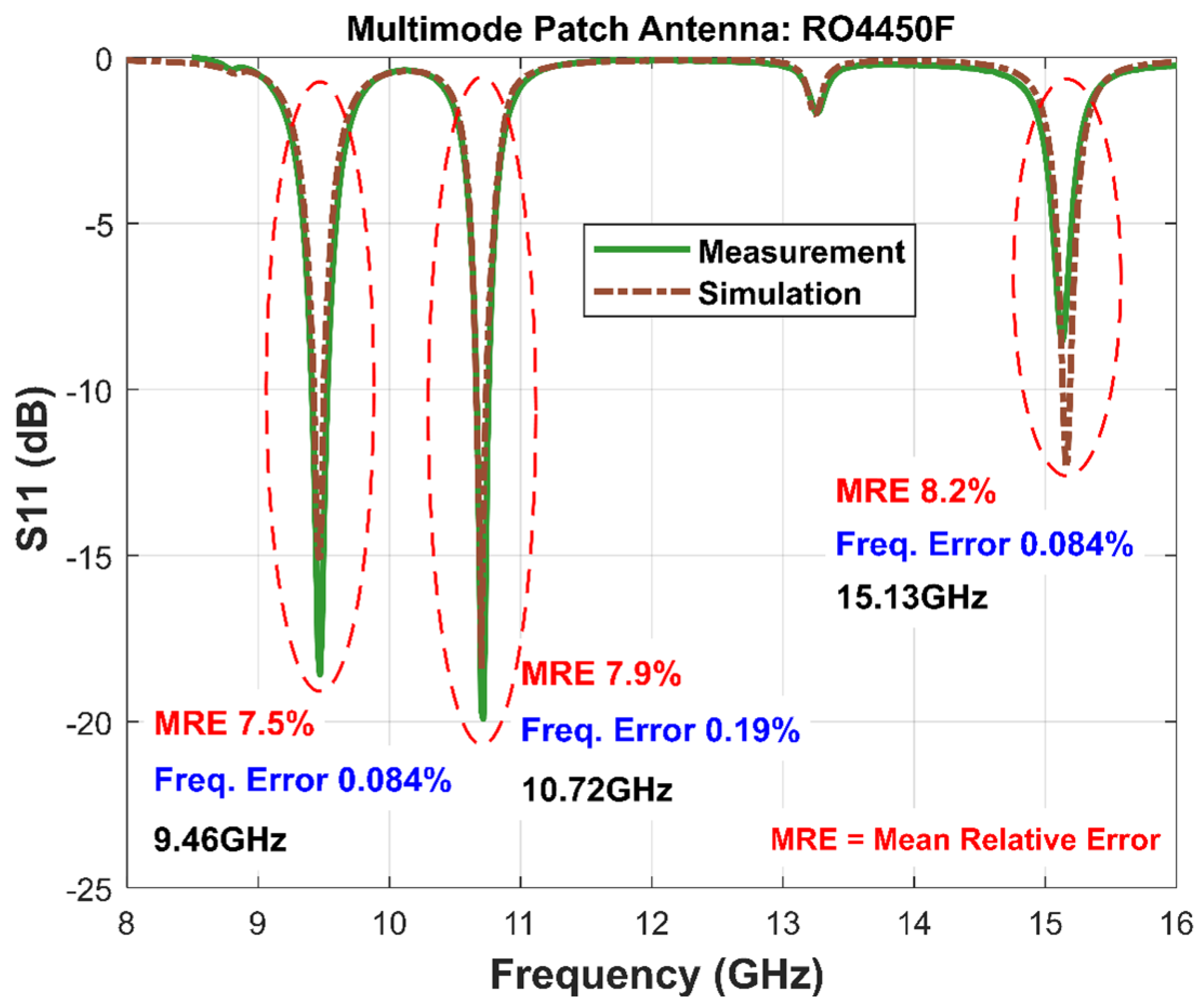
The illustrations in
Figure 5 and
Figure 6 vividly display the
outcomes for each substrate under examination. The precision of the characterization method is manifest, and all MRE indicators - calculated on the targeted curve segments - remain well within the 10% limit. Similarly, Freq.Error metrics did not exceed the 0.2% mark, aligning seamlessly with the procedural criteria established in
Section 2.2. the multimode antenna on the RO4350B substrate (
Figure 5), where MRE values for all operational modes registered at 9.6%, 8.6%, and 7.1%, and Freq. Error rates at 0.053%, 0.15%, and 0.063%, respectively. The corresponding resonant frequencies were pinpointed at 9.37 GHz, 10.63 GHz, and 15.01 GHz, underscoring the robustness of the characterization method and its successful application across a spectrum of substrates.
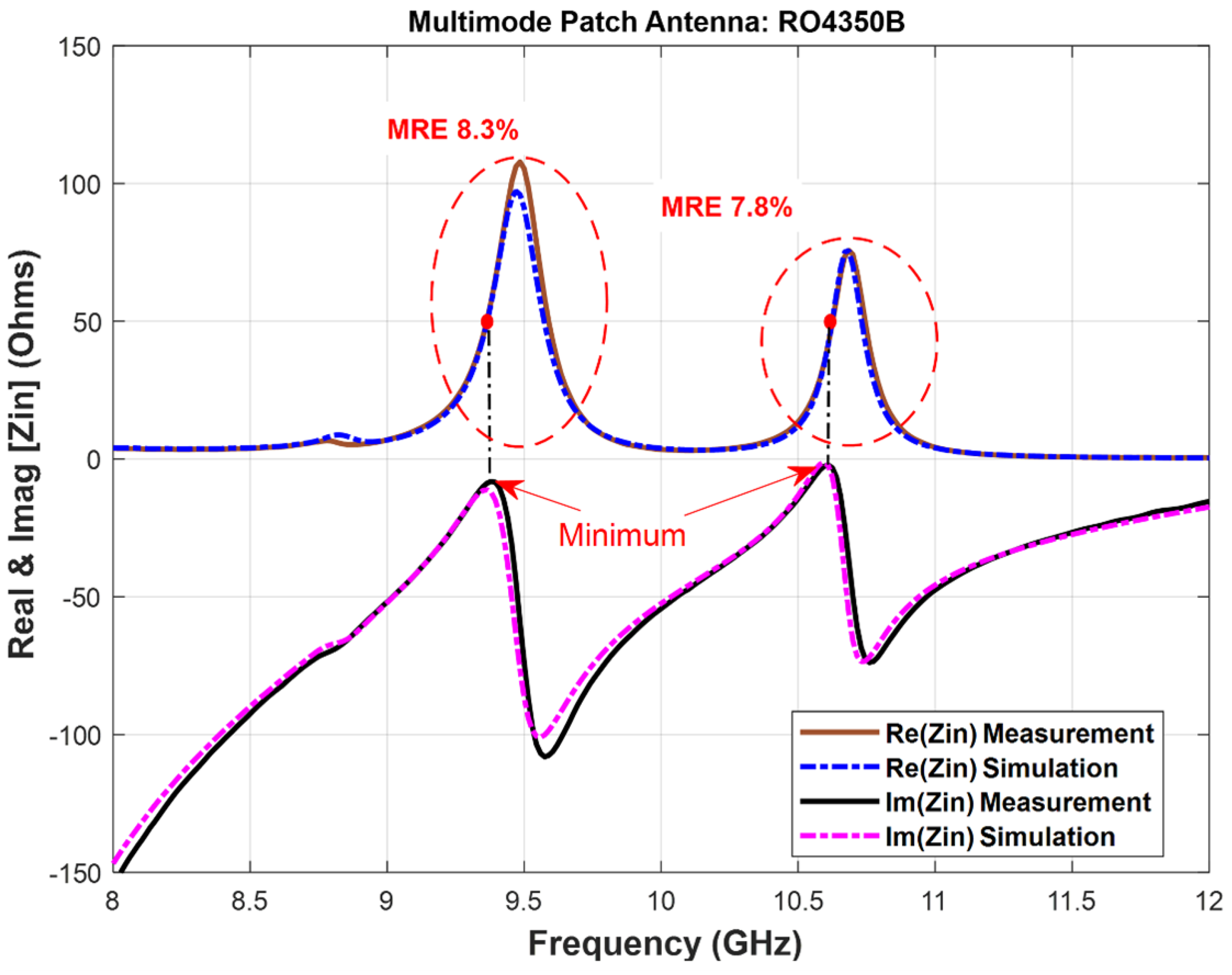
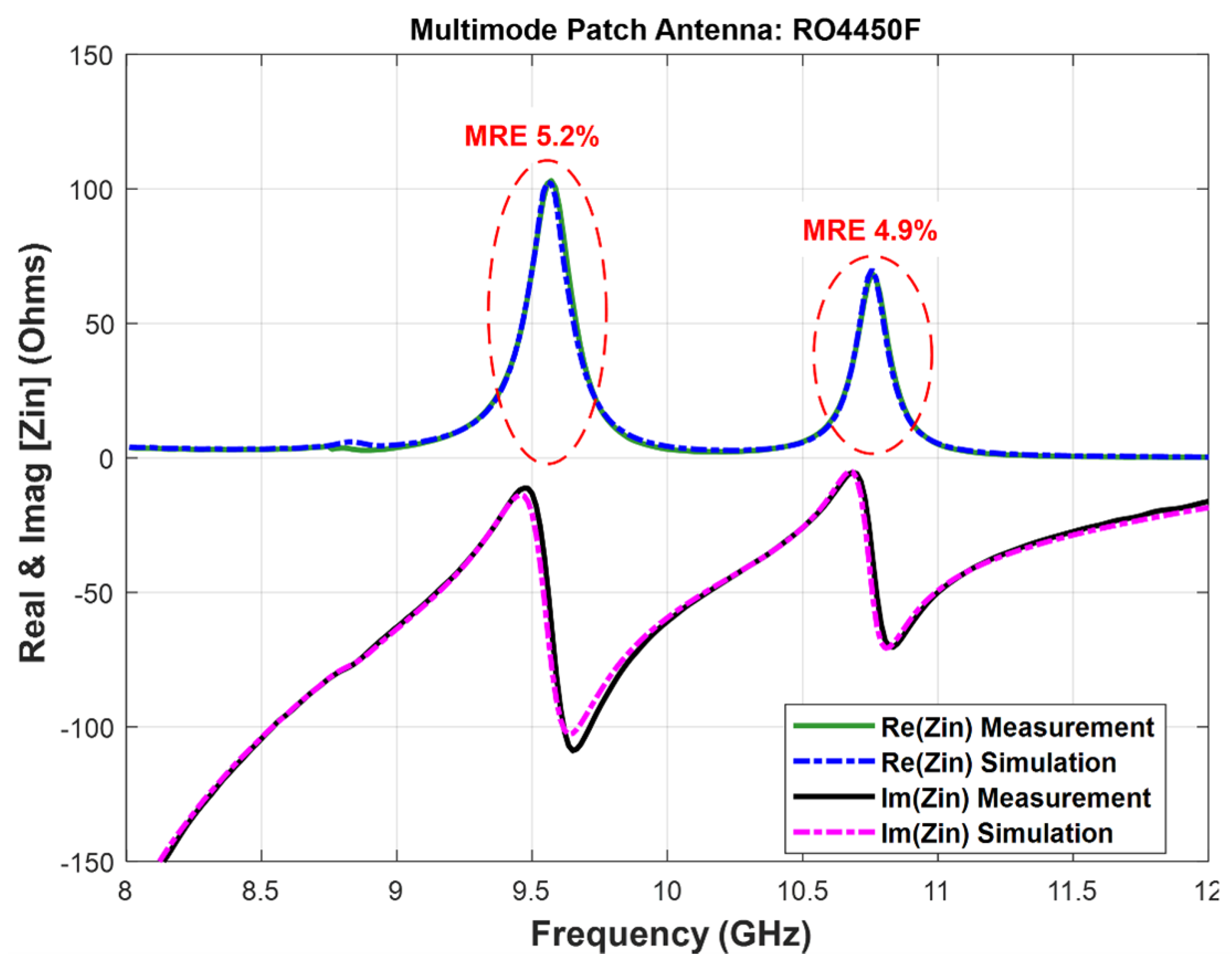
For in-depth validation of the consistency of the fitting process, the real and imaginary parts of the antenna’s input impedance are detailed in
Figure 7 and
Figure 8. An exhaustive analysis reveals that all the accuracy metrics computed on the real [
] curves (MRE) stay uniformly below an 8. 3% margin for all modes and substrates. Importantly, the impedance values align closely with theoretical expectations, with Real(
) approximating 50
and Imag(
) nearing 0
at the identified resonant frequencies - evidenced by the lowest point in
. These findings not only validate the reliability and effectiveness of the proposed characterization method but also emphasize its potential for broad application in the field, paving the way for enhanced antenna design and substrate analysis.
3.3. Monomode Antenna Design:
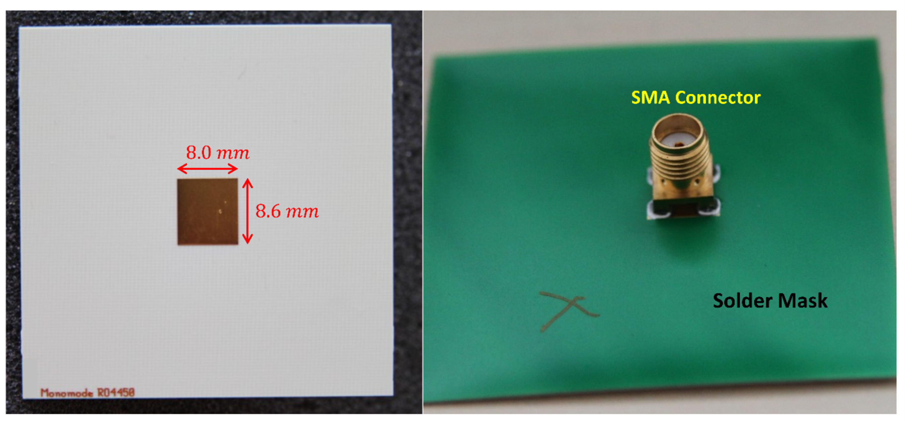
During the validation phase of our study, a dedicated effort was made to design and fabricate a monomode antenna for each of the selected substrates, with the objective of achieving operation at a resonant frequency of approximately 8.5 GHz. The detailed specifications of these antennas, including their physical dimensions, are meticulously documented in
Table 4. Each radiating patch was constructed using a copper layer with a thickness of 1 oz or
, ensuring consistency in the material quality across all samples.
Figure 9 offers a visual presentation of the fabricated monomode antenna, highlighting its integration with an SMA connector. This particular instance features the antenna designed for the RO4450F substrate, serving as a representative example of the craftsmanship and precision engineering involved in the process. The simulation efforts were enhanced by the inclusion of exact details pertaining to the connector’s model—spanning both its dimensions and dielectric material properties—to ensure a high fidelity between the simulated models and their real-world counterparts. This phase underscores the meticulous attention to detail and methodological rigor employed in validating our characterization method. By incorporating precise models of the SMA connectors into the simulation, we not only enhance the accuracy of our predictions but also validate the practical applicability of our designs.
3.4. Monomode Antenna Results:
The conclusive phase of the characterization method involved meticulous measurements and comparisons against design simulations conducted using CST Microwave Studio and ADS FEM, predicated on the optimal values of
and
identified in the preceding step. This rigorous approach, grounded in the accuracy indicators specified in
Section 2.3 (MRE on
,
), has yielded compelling results that underscore the robustness and precision of the method.
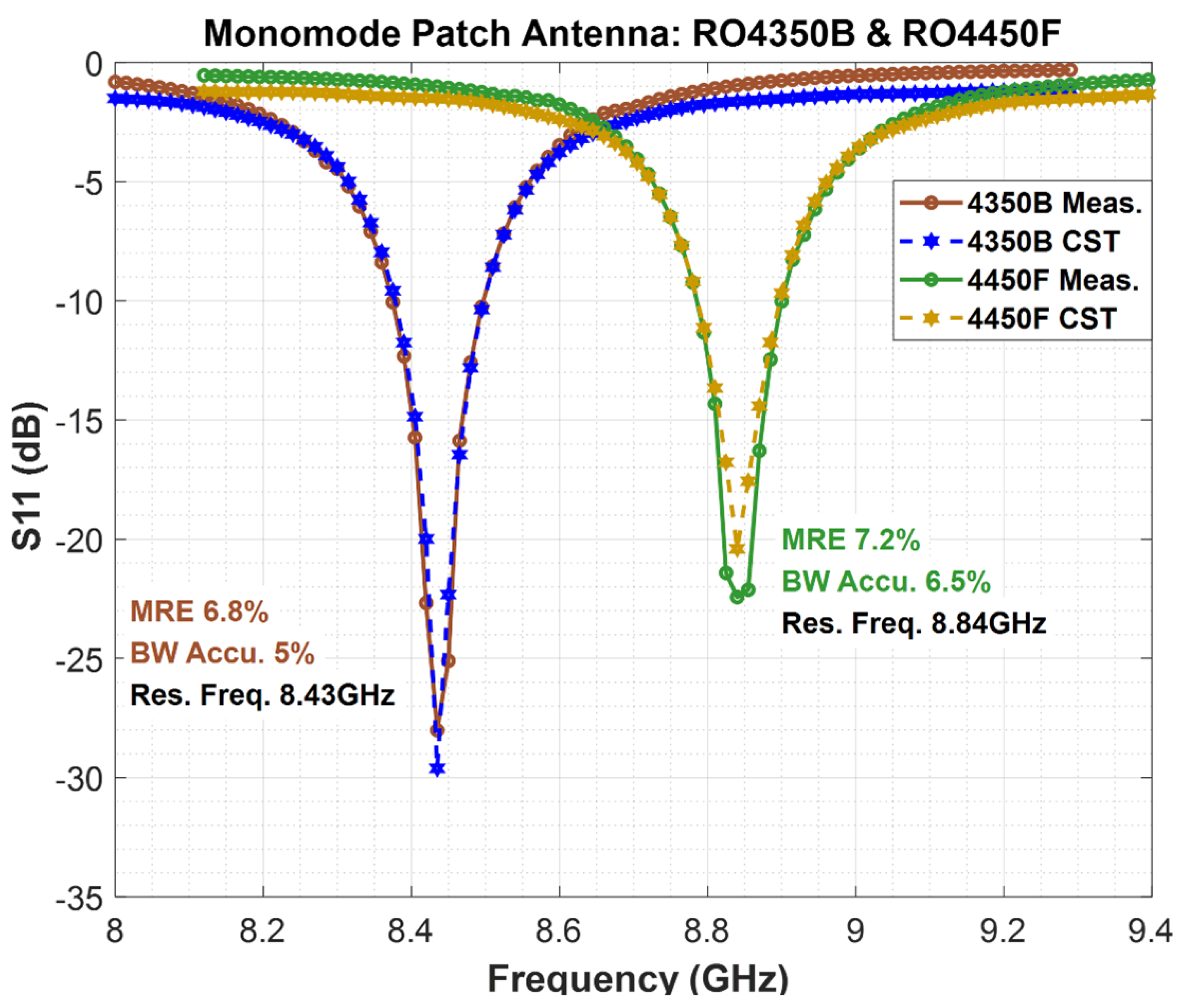
Figure 10 insightfully presents the
findings for the monomode antennas constructed on the RO4350B and RO4450F substrates, revealing MRE values below 7.2%, thus indicating a high degree of measurement-simulation correlation at 92.8%. Furthermore, the relative errors on
are confined below 6.5%, signifying that the simulated matching bandwidth is remarkably 93.5% accurate relative to the measured bandwidth. These results, showing measured resonant frequencies of 8.43 GHz and 8.84 GHz that perfectly align with simulations, validate the efficacy of the simulations and the precision of the characterization method.
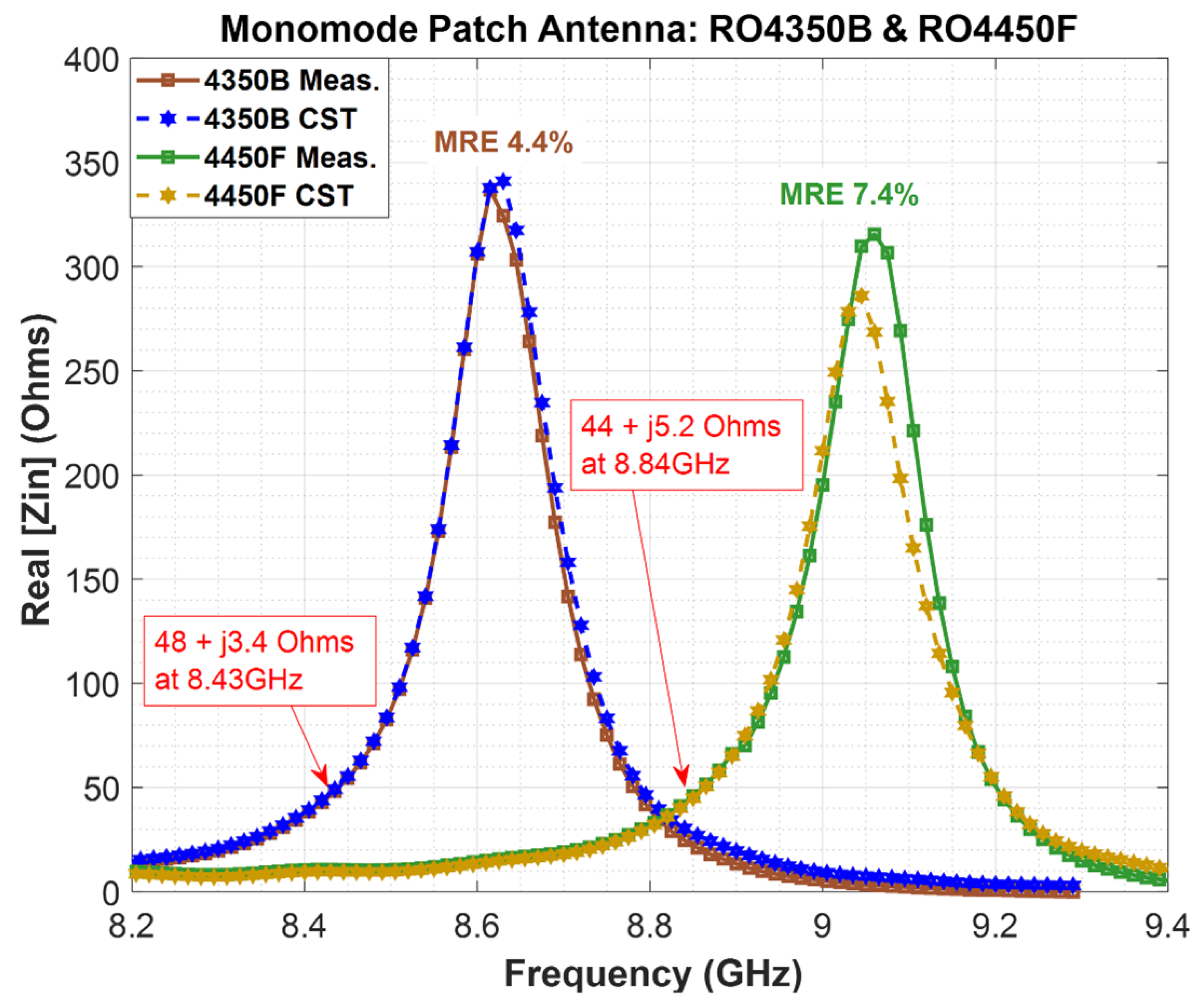
Figure 11 further validates the method’s accuracy through the input impedance
results for the antennas on RO4350B and RO4450F substrates. The ideal match is evidenced when
closely approximates
and
is near
at the specified resonant frequencies, a condition that is visually confirmed by the red points in
Figure 11, depicting measured real and imaginary parts of
. The quality of the matching is proven if
and
at the above resonant frequencies. This is shown by the red points on
Figure 11, where the measured real and imaginary parts at the corresponding resonant frequencies are
and
, respectively.
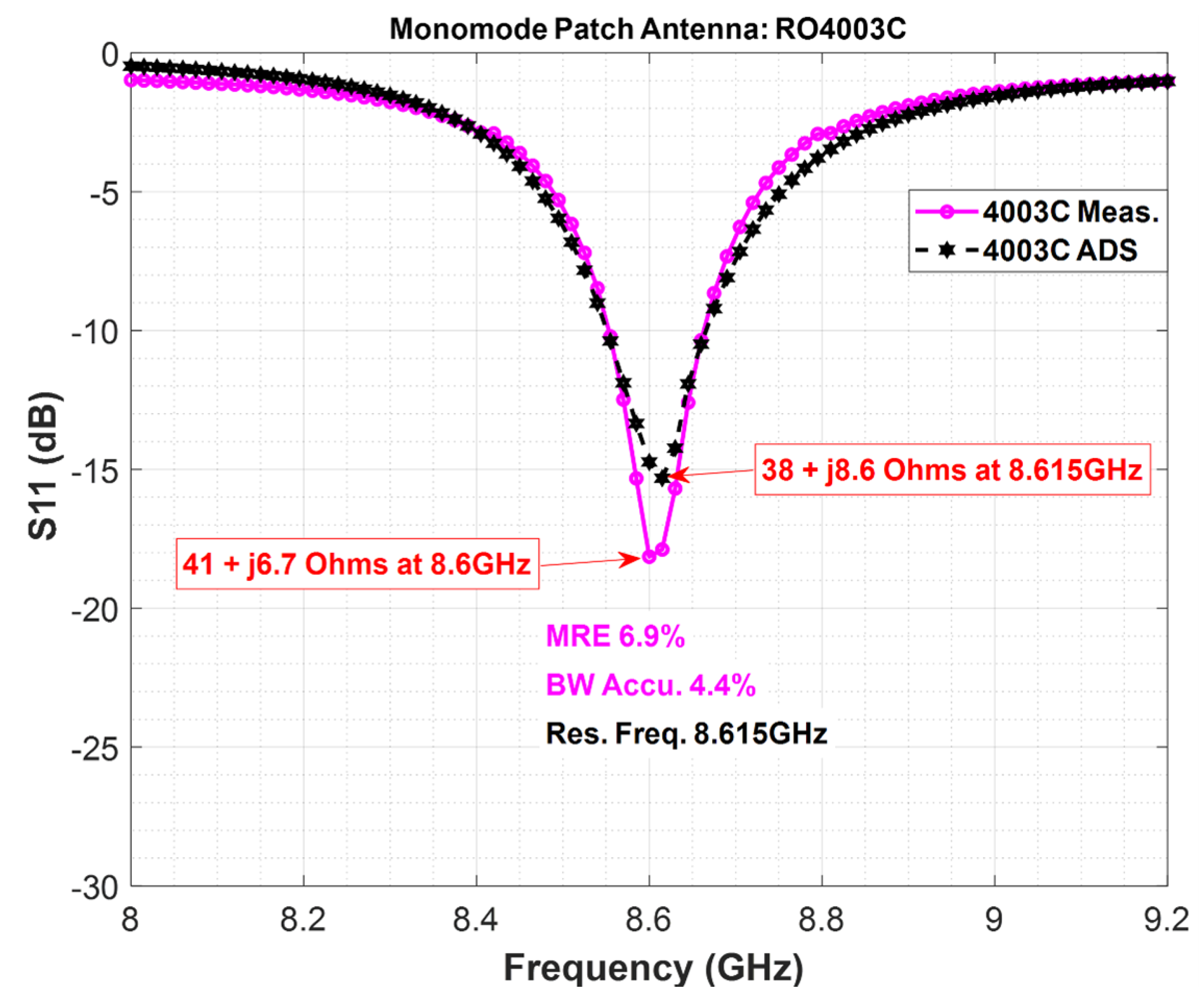
Figure 12 extends this validation to the monomode antenna fabricated on the RO4003C substrate, analyzed using the ADS simulator. The MRE on the
curve being below 7% achieves a 93% measurement-simulation correlation, with a relative error on
under 5%, thereby indicating a 95% accuracy of the simulated matching bandwidth compared to the measured one. The resonant frequency measured at 8.6 GHz, only 15 MHz away from the simulated 8.615 GHz, further corroborates the method’s precision.
These findings collectively affirm the characterization method’s reliability and effectiveness, showcasing its capability to yield highly accurate simulations that closely mirror actual measured performances. Such accuracy across various substrates and simulation environments heralds a significant advancement in antenna design and analysis, highlighting the method’s potential for broad application and its contribution to enhancing the precision of electromagnetic simulations in the field.
4. Strengths and Limitations of the Proposed Methodology
One of the key strengths of this study lies in the wideband nature of the proposed method, effectively covering the 8–16 GHz frequency range. This broad range enhances the versatility of our technique, making it applicable across various industrial and academic sectors, where wideband antennas are critical for applications such as radar systems, telecommunications, and material characterization. Unlike conventional narrowband approaches, our method ensures a more comprehensive evaluation of substrate performance across different frequencies, making it more attractive for a broader set of real-world applications.
Additionally, the iterative and retrospective nature of our simulations represents a significant advancement over traditional, one-dimensional approaches. By continuously refining the simulation models based on preliminary results, we were able to fine-tune the designs more efficiently, leading to more accurate predictions and better overall performance. This process not only optimizes antenna design but also reduces development time, offering significant value to industries where rapid prototyping and validation are essential.
Despite the promising outcomes, the study is not without its limitations. One potential drawback is the reliance on destructive testing methods during certain stages of the process, which may not be ideal in environments where non-destructive evaluation is preferred. Furthermore, while the frequency range of 8–16 GHz is adequate for many applications, some specific high-frequency applications may require an extended range beyond 16 GHz.
5. Conclusion and Future Work
In this study, we introduce a cost-effective and accessible approach for accurately characterizing dielectric substrate materials, utilizing rectangular-shaped patch antennas. This three-phase technique encompasses the design, manufacture, and measurement of and for a wideband multimode patch antenna; the numerical optimization of and based on simulation data to align closely with measurements from the first phase; and the design and validation of a monomode patch antenna informed by the refined and values. Distinguished by its wideband nature, this method is straightforward to implement in both academic and industrial settings, reducing the need for sophisticated or costly equipment.
The utility and reliability of this method were rigorously evaluated on three distinct types of low thin-film substrate materials using two electromagnetic (EM) simulation platforms that employ different solver technologies (time and frequency domain). The empirical validation demonstrated a strong agreement between the experimental measurements and the simulations, with a mean relative error below 10% on the curve and a resonant frequency deviation less than 0.2% across all resonant modes.
Additionally, this paper addresses the challenges posed by fringing field effects and surface wave propagation commonly encountered in thin-film substrates (height mm). These effects can significantly impact the performance of patch antennas, particularly at low heights, leading to inaccuracies in substrate characterization. Our approach provides a robust pre-design assessment tool that helps mitigate these issues by refining the dielectric properties, ultimately enhancing antenna performance.
Future work should focus on addressing these limitations by exploring non-destructive variations of the current method, allowing for the evaluation of substrate materials without permanent alteration or damage. Additionally, extending the frequency range and testing the proposed method on alternative substrate types (e.g., flexible substrates, advanced composites) would further validate its robustness and broaden its potential for deployment in emerging technologies, including flexible electronics and 5G/6G applications.
Author Contributions
Georges Zakka El Nashef and Abdel Karim Abdel Karim contributed to the conceptualization of the study. The methodology was developed by Georges Zakka El Nashef and Abdel Karim Abdel Karim. Georges Zakka El Nashef was responsible for implementing the software and conducting the measurements. The validation of the results was carried out by Georges Zakka El Nashef, Abdel Karim Abdel Karim, and Sawsan Sadek. Abdel Karim Abdel Karim performed the formal analysis and contributed to the optimization of the design. The investigation and data collection were conducted by Georges Zakka El Nashef, who also provided the necessary resources. Georges Zakka El Nashef prepared the original draft of the manuscript, while Sawsan Sadek reviewed and edited the content. Abdel Karim Abdel Karim was responsible for the visualization and graphical representation of the data. Sawsan Sadek supervised the overall research process. The project administration was managed by Georges Zakka El Nashef. All authors have read and approved the final version of the manuscript.
Funding
No funding was received from any financial organization to conduct this research.
Acknowledgments
We would like to extend our gratitude to XLIM Laboratory for their invaluable support and provision of materials. Their expertise in high-frequency electronics greatly facilitated our research. We also acknowledge their contribution to covering the manufacturing process costs, which was essential for the successful completion of this study. Additionally, we thank all individuals who provided their assistance and insights during the research process. Your support has been instrumental in achieving the results presented in this paper.
Conflicts of Interest
The authors declare that they have no known financial or non-financial competing interests in any material discussed in this paper.
References
- Balanis, C.A. Advanced Engineering Electromagnetics, 2nd ed.; John Wiley & Sons: New York, NY, 2012; p. 1018. [Google Scholar]
- Coonrod, J.; Horn, A.F. Understanding dielectric constant for microwave PCB materials. High Frequency Electronics 2011, 10, 18–23. [Google Scholar]
- Bronckers, L.A.; Smolders, A.B. Broadband material characterization method using a CPW with a novel calibration technique. IEEE Antennas and Wireless Propagation Letters 2016, 15, 1763–1766. [Google Scholar] [CrossRef]
- Sun, H.; et al. Symmetric coplanar waveguide sensor loaded with interdigital capacitor for permittivity characterization. International Journal of RF and Microwave Computer-Aided Engineering 2020, 30, 1–9. [Google Scholar] [CrossRef]
- Sun, H.; Tang, T.; Du, G. Improved approach using symmetric microstrip sensor for accurate measurement of complex permittivity. International Journal of RF and Microwave Computer-Aided Engineering 2018, 28, 1–9. [Google Scholar] [CrossRef]
- Mbango, F.M.; Ndagijimana, F. Electric Parameter Extractions Using a Broadband Technique from Coaxial Line Discontinuities. International Journal of Scientific Research and Management 2019, 7, 248–253. [Google Scholar] [CrossRef]
- Scott, M.M.; Morris, A.P.; Reid, D.R.; Bean, J.A. Broadband isotropic and anisotropic permittivity determination using partially filled coaxial airlines. Microwave and Optical Technology Letters 2015, 57, 1864–1868. [Google Scholar] [CrossRef]
- Chung, D.D.L. Pitfalls and Methods in the Measurement of the Electrical Resistance and Capacitance of Materials. Journal of Electronic Materials 2021, 50, 6567–657. [Google Scholar] [CrossRef]
- Pradhan, A.K.; Maiti, S.; Biswas, S.K.; Mondal, S.; Maiti, M.; Bhattacharyya, K. Measurement of complex dielectric permittivity of medium and low loss materials at 36.624 GHz and 52.263 GHz using a single iris rectangular cavity resonator. Indian Journal of Physics 2024, 98, 2059–2075. [Google Scholar] [CrossRef]
- Baker-Jarvis, J.; Janezic, M.D.; DeGroot, D.C. High-Frequency Dielectric Measurements; IEEE Instrumentation & Measurement Magazine, 2010; pp. 24–31. [Google Scholar] [CrossRef]
- Coonrod, J. Methods for Characterizing the Dielectric Constant of Microwave PCB Laminates. Microwave Journal 2011, 54, 132–144. [Google Scholar]
- Norooziarab, M.; Bulja, S.; Cahill, R.; Kopf, R.; Tate, A. Complex dielectric permittivity extraction based on multilayer thin film microstrip lines. IET Microwaves, Antennas & Propagation 2017, 11, 955–960. [Google Scholar] [CrossRef]
- Hirano, T.; Okada, K.; Hirokawa, J.; Ando, M. Accuracy Investigation of De-Embedding Techniques Based on Electromagnetic Simulation for On-Wafer RF Measurements. In Numerical Simulation From Theory to Industry; IntechOpen: London, UK, 2012; pp. 233–258. [Google Scholar] [CrossRef]
- Gao, M.; Xie, Y.; Li, Q.; Miao, Y. Calculation of complex permittivity for shielding effectiveness equivalence. In Proceedings of the IEEE International Conference on Environment and Electrical Engineering and 2017 IEEE Industrial and Commercial Power Systems Europe (EEEIC / I&CPS Europe); 2017. [Google Scholar] [CrossRef]
- Dankov, P.I. A method for determination of equivalent dielectric constant of planar transmission lines on anisotropic substrates with dielectric overlay. In Proceedings of the 2017 International Workshop on Antenna Technology: Small Antennas, Innovative Structures, and Applications (iWAT), 2017. [CrossRef]
- Corporation, R. RO4000® Series Data Sheet, High Frequency Circuit Materials, 2018. Available online: https://rogerscorp.com/advanced-connectivity-solutions/ro4000-series-laminates/ro4003c-laminates.
|
Disclaimer/Publisher’s Note: The statements, opinions and data contained in all publications are solely those of the individual author(s) and contributor(s) and not of MDPI and/or the editor(s). MDPI and/or the editor(s) disclaim responsibility for any injury to people or property resulting from any ideas, methods, instructions or products referred to in the content. |
© 2025 by the authors. Licensee MDPI, Basel, Switzerland. This article is an open access article distributed under the terms and conditions of the Creative Commons Attribution (CC BY) license (http://creativecommons.org/licenses/by/4.0/).