1. Introduction
In mechanical systems, rotors play an extremely important role whose performance directly determines the operational stability and efficiency of the entire mechanical equipment. Rotors commonly used in engineering are predominantly solid or hollow with circular cross-sections, offering excellent stability due to their circumferential symmetry. However, in practical engineering practices, factors such as complex manufacturing processes, specific installation requirements, material property variations, and diverse working conditions often result in the use of rotors with circumferentially asymmetric cross-sections. Examples include gun drill rods and BTA drill rods used in deep hole drilling. These rods must rotate to perform cutting operations while simultaneously allowing high-pressure cutting fluid to flow into the cutting area and facilitating chip removal. The difference between these two types lies in the flow path of the cutting fluid; to be specific, for gun drill rods, the fluid flows through the interior of the drill rod, and chips are discharged from the chip groove; whereas for deep hole drill rods, the fluid flows through the gap between the drill rod and the workpiece, with chips discharged through internal holes within the drill rod. This functional design imparts circumferential asymmetry to their cross-sections. The irregularity of such cross-sections significantly complicates the determination of parameters such as moment of inertia, centroid position, and anisotropic material properties, in contrast to symmetric cross-sections. Therefore, researchers need to account for these complex factors during the modeling process to ensure the model accurately represents the structural characteristics and facilitates subsequent theoretical analysis and numerical calculations. From a theoretical perspective, the study of shafts with circumferentially asymmetric cross-sections greatly expands the scope of traditional rotor dynamics analysis, and in-depth exploration of asymmetric rotors contributes to the advancement and enrichment of the theoretical system of rotor vibration analysis.
The dynamic characteristics of circumferentially symmetric rotors and rotor systems with various materials and structural forms have been extensively studied; however, research on the dynamic characteristics of rotors with circumferentially asymmetric cross-sections remains relatively rare.
P. Jamshidi et al. [
1] analyzed the nonlinear vibration in a rectangular cross-section rotor system using a multiscale method, demonstrating that asymmetry has a significant impact on the dynamic characteristics of the rotor system. Bavi R et al. [
2] conducted dynamic analysis on composite laminated rotors, employing rectangular sections to simulate the geometric asymmetry of the cross-section, accounting for gyroscopic coupling effects, and utilizing Euler angles to achieve angular velocity. Their research encompassed multiscale analytical studies of parameter excitation systems under both resonant and non-resonant conditions. In deep hole machining, the substantial hole depth necessitates slender drill rod structures, resulting in low structural rigidity. The consequent vibration problem during the working process significantly affects machining efficiency and the surface quality of the hole. This has prompted extensive research interest in deep hole drilling, with primary focus areas including surface quality issues [
3,
4], vibration suppression and process optimization [5-8], and innovative shock-absorbing drill rod design [9-12]. However, studies on the stability of free vibration in drill pipes are relatively limited. Quanbin Zhang et al. established a fluid-structure coupled transverse vibration differential equation for boring bars using Hamilton’s principle, taking into account the effects of bending, torsion, and axial deformation. The transverse vibration characteristics were solved through application of the Galerkin method [
13]. This model can be used to analyze the relationships between system stability and key parameters including equivalent stiffness, equivalent shear modulus, and axial force. L. Li et al. [
14] developed a dual nonlinear damping model and explored its damping mechanisms under nonlinear stiffness. Bayly [
15] compared theoretical predictions with experimental results, analyzed the torsional vibration of the drill pipe system, and provided a detail analysis of the distribution range of tool chatter frequencies and stability criteria, ultimately revealing significant nonlinear characteristics in the drill pipe system during deep hole machining.
Previous dynamic analyses have typically employed either predetermined equivalent stiffness for drill pipes or modeled them as circumferentially symmetric circular or hollow circular section rods. This study takes the gun drill rod as an example for analysis, and models it as a cantilever beam structure with asymmetric cross-section. The research method encompasses the development of free vibration equations within a dynamic coordinate system, analysis of free vibration characteristics and stability parameters for asymmetric shafts, and validation through ANSYS finite element analysis, thereby establishing a relatively complete analytical system.
2. Materials and Methods
2.1. Mechanical Model
The structure of the gun drill, as shown in
Figure 1, consists of three main components: the drill blade, drill pipe, and drill handle. The drill handle serves as the connection point with machine tools, while the drill blade performs cutting operation. This study focuses on the analysis of the drill pipe section, disregarding the structural characteristics of the drill blade. For dynamic analysis, the drill pipe is simplified as an isotropic cantilever beam with a circumferentially asymmetric cross-section, as shown in
Figure 2.
To facilitate analytical and computational efficiency, the drill pipe cross-section is assumed to have a symmetrical axis (oraxis). The axes and represent the centroidal principal inertial axes of the section. The bending vibration of the drill rod predominantly occurs in the direction corresponding to the minimum moment of inertia, which correlates with minimum bending stiffness. Point C denotes the centroid of the cross-section, with the corresponding axes and serving as the principal inertial axes through this centroid. The cross-sectional area is designated as A, and the distance from the centroid to the coordinate origin is represented by and . Therefore, the principal moment of inertia through the centroid is defined as:
(1)
(2)
where
2.2. Vibration Equation of the Rayleigh Rotor for Gun Drill Rod
Based on literature [16-17], the vibration equation of the Rayleigh rotor in a dynamic coordinate system is expressed as:
(3)
(4)
where and represent the displacement of the cross-sectional centroid along the and axes, respectively. denotes the angular velocity of the drill rod rotation, and represents the density of the drill rod material. Comparing equations (1) and (2), it is evident that and characterize the effects of Coriolis acceleration, while and represent the rotational inertia forces.
2.2. Solution Methods
The study employs the Galerkin approximation method, a widely used technique for vibration and stability analysis of continuous systems. This approach utilizes assumed vibration modes to eliminate spatial position variables of the blades, thereby transforming the free vibration equation into a time-dependent ordinary differential equation.
For the cantilever shaft analysis, the bending deformation is expressed as the following formulation:
(5)
The bending mode function of a standard uniform cantilever beam is defined as:
(6)
Substituting equations (5) and (6) into vibration differential equations (3) and (4), and applying the Galerkin method with weighted integration of mode functions, a system of 2N ordinary differential equations is derived:
(7)
where
The matrix elements are defined as:
The solution of equation (7) yields the free vibration characteristics of the circumferentially asymmetric cross-section.
3. Results
3.1. Reliability analysis
Analysis was conducted on a steel drill rod with the following specifications: L=0.4m, D=0.04m, d=0.01m, a=0.01m,
θ=45
⸰, E=210GP, G=210GP, and material density of
ρ=7800kg/m
3. The relationship between natural frequency and rotational speed is shown in
Figure 3.
From
Figure 3, the natural frequency values in the dynamic coordinate system can be distinctly categorized into two types with increasing rotational speed: forward motion and backward motion. When the backward motion frequency approaches 0, the system becomes unstable. Due to the circumferential asymmetry of the rotor structure, the frequency values for backward motion can attain 0 or negative values within specific speed ranges (negative values are represented as 0 in the plot).
Figure 3 also compares the theoretical analysis results presented in this study with the ANSYS simulation results, which demonstrates a high degree of consistency between the two, thereby validating the reliability of the results in this study.
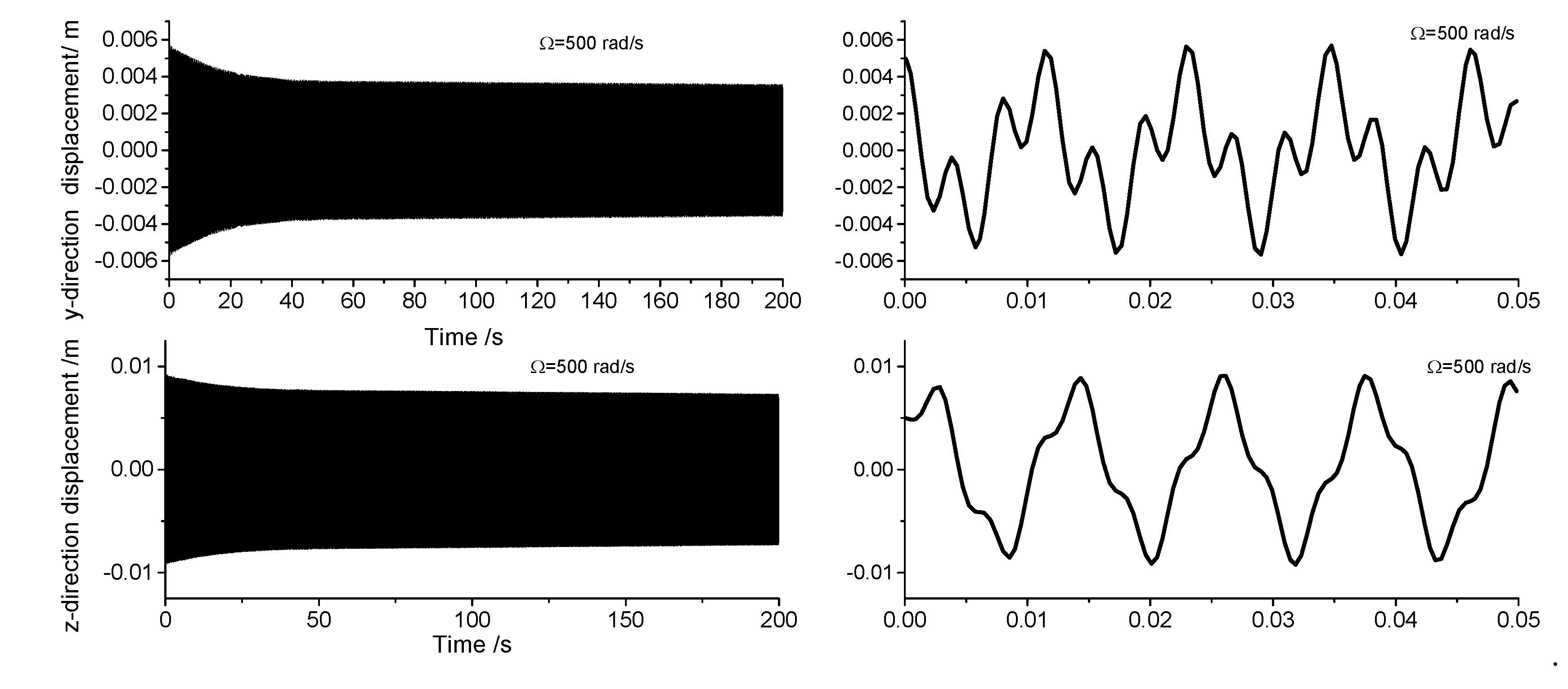
Displacement response analysis is employed to analyze the drill rod behavior when the first-order frequency approaches zero. Due to the circumferential asymmetry of the rotor, the gun drill rod exhibits eccentricity. Under centrifugal force conditions, with specified initial displacement and velocity parameters, the Runge-Kutta method is implemented through the ODE45 function in MATLAB to analyze displacement responses at varying rotational speeds.
Figure 4,
Figure 5,
Figure 6 and
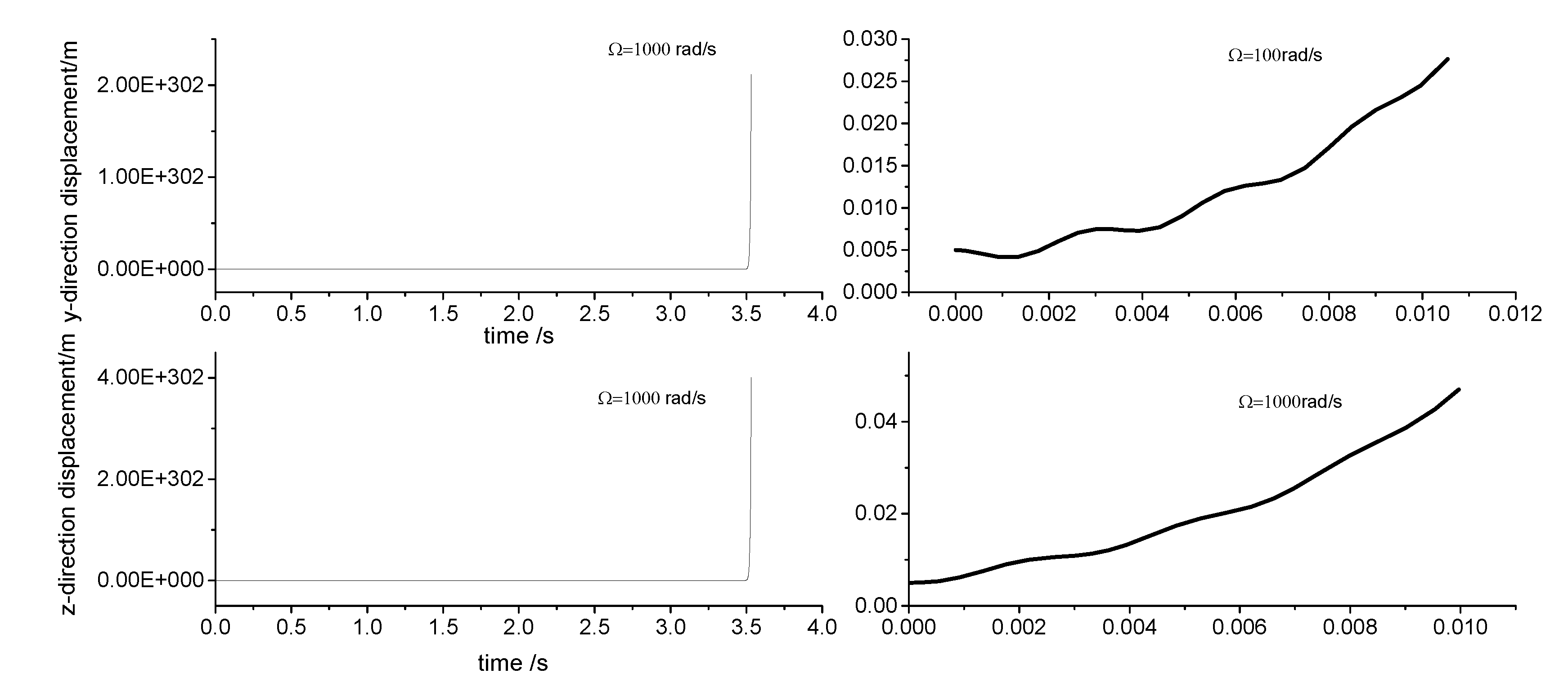
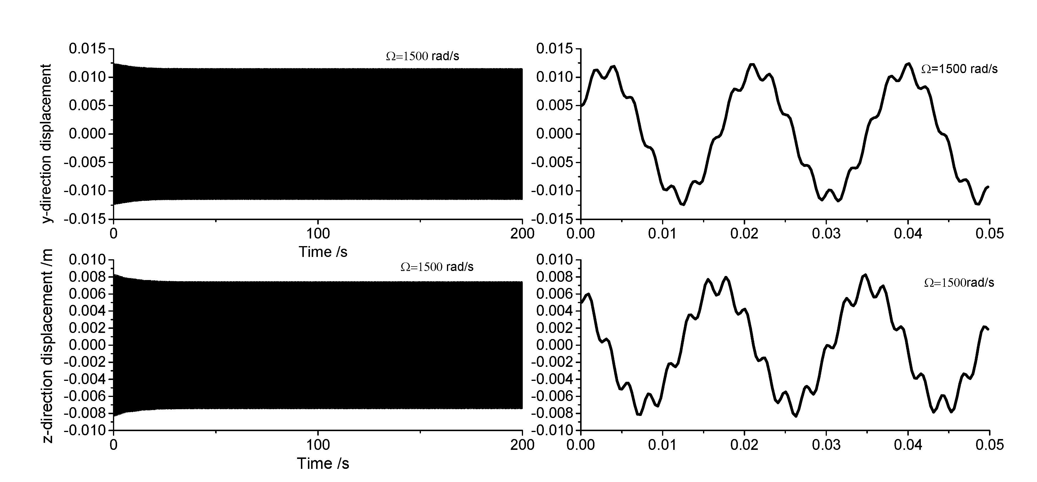
Figure 7 illustrate the displacement responses from 0 to 200 second at different rotational speeds. Under identical initial conditions, the displacement response converges at rotational speeds of 100rad/s, 500rad/s, and 1500rad/s. At lower speeds, the amplitude of the steady-state response is small. However, as the speed increases, the inertial force intensifies proportionally, resulting in increased steady-state response amplitudes. At
=1000rad/s, the displacement diverges rapidly, indicating the existence of a rotational speed instability region for the circumferential asymmetric rotor.
3.2. Influence of Dimensional Factors on Vibration Stability
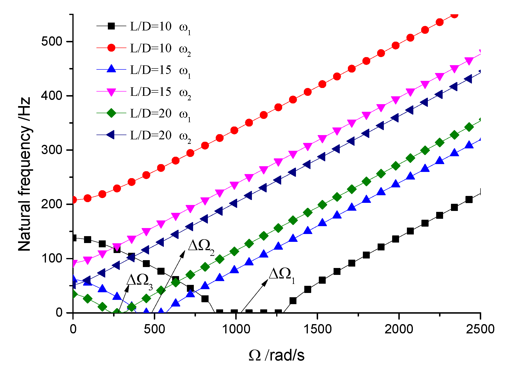
This section analyzes the influence of various dimensional parameters of the gun drill rod on its free vibration and stability. As shown in
Figure 8, increasing aspect ratio leads to a progressive decrease in both drill rod stiffness and natural frequency. According to calculations, we obtain
rad/s,
rad/s, and
rad/s. The results suggest that as the aspect ratio increases and natural frequency decreases, the unstable region correspondingly diminishes. Based on
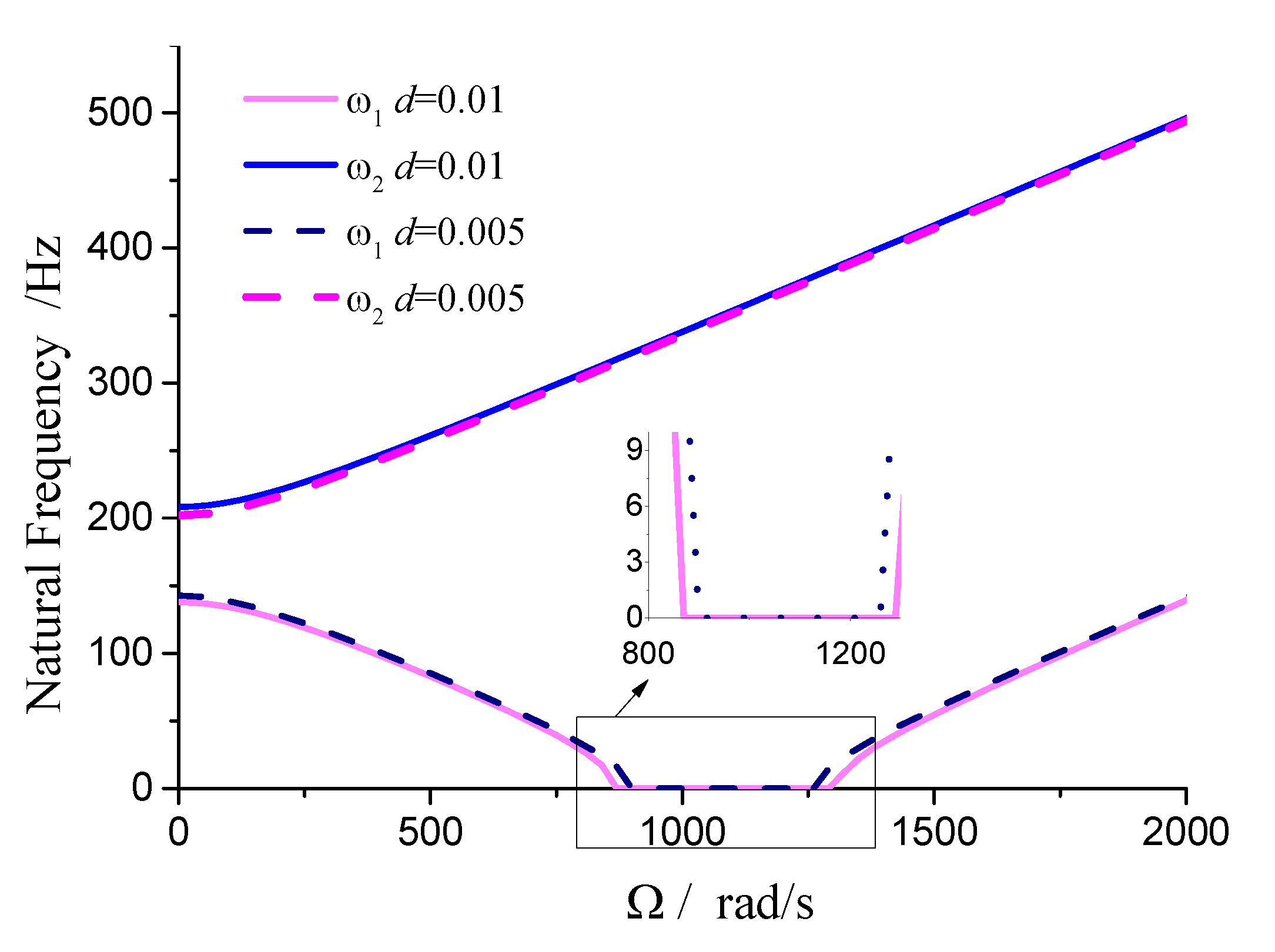
Figures 8, 9, 10, and
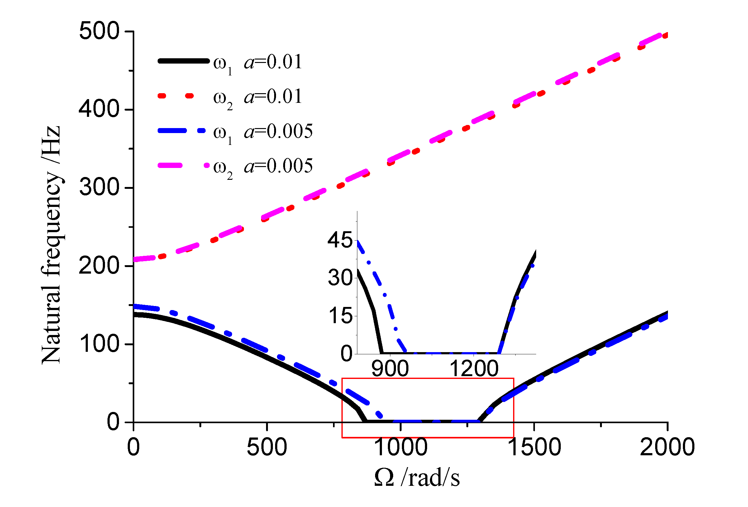
Table 1, it can be seen that the dimensions of the cutting fluid inlet have minimal impact on natural frequency values. However, reducing the cutting fluid inlet dimensions narrows the speed range of the unstable region (441-371=70 rad/s). Decreasing the distance from the cutting fluid inlet to the center of the outer circle only affects the stiffness of the gun drill along the
axis, resulting in a variation in the first-order frequency alone. Conversely, reducing the distance between the cutting fluid inlet and the shaft increases the stiffness along the
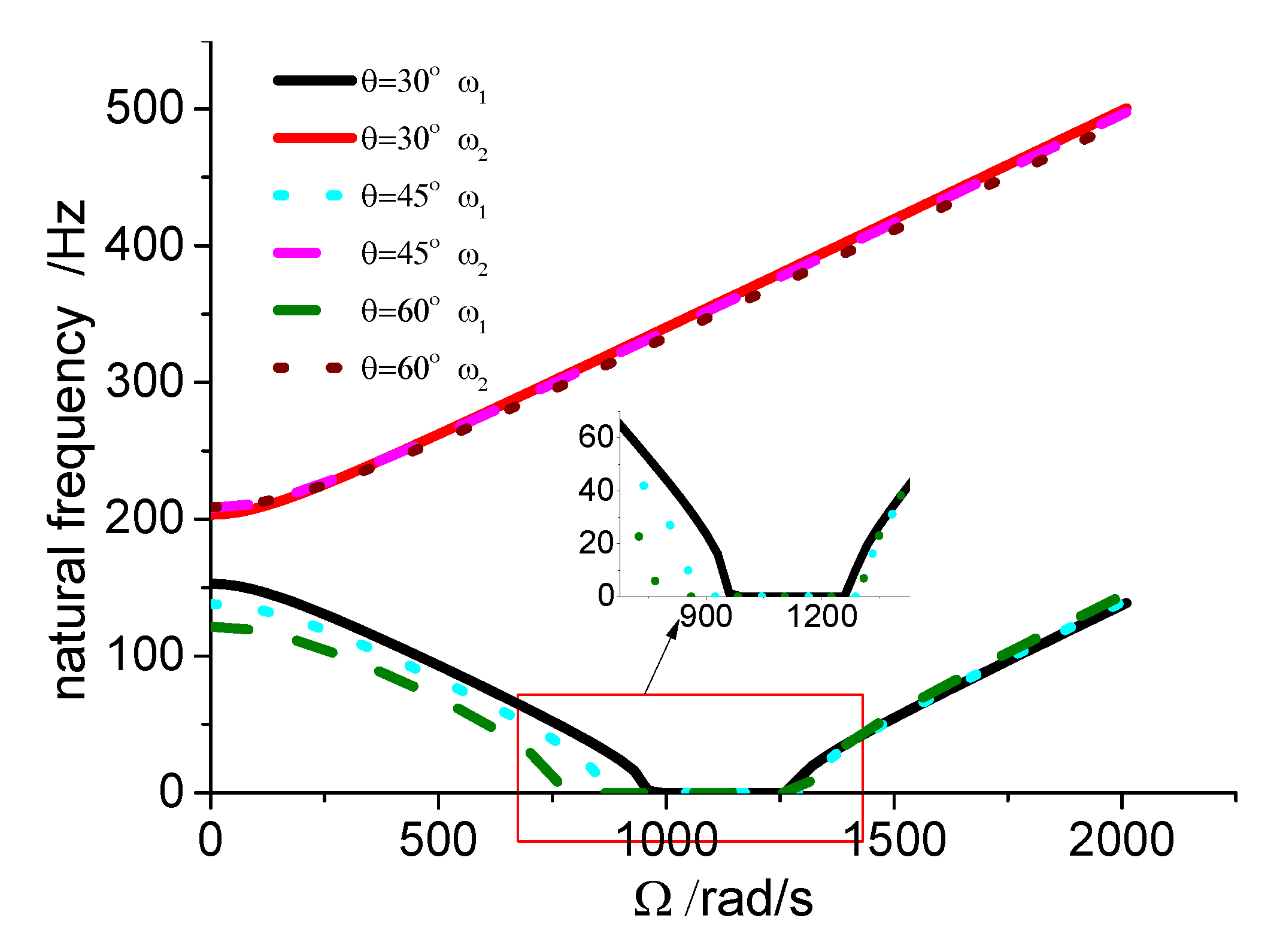
axis, leading to higher first-order natural frequency values while simultaneously narrowing the speed range of the unstable region (441-374=67 rad/s). The dimensions of the chip removal groove significantly influence the first-order frequency, while the second-order frequency remains relatively constant. Smaller chip groove dimensions correlate with higher first-order frequencies and reduced unstable regions (from 441 rad/s to 316 rad/s). While increasing chip removal groove dimensions enhances chip removal efficiency, it simultaneously introduces greater system instability.
Figure 8.
Influence of aspect ratio on stability.
Figure 8.
Influence of aspect ratio on stability.
Figure 9.
Influence of cutting fluid inlet dimensions on stability (L=0.4m, a=0.01m, α=45 º).
Figure 9.
Influence of cutting fluid inlet dimensions on stability (L=0.4m, a=0.01m, α=45 º).
Figure 10.
Influence of cutting fluid inlet position.
Figure 10.
Influence of cutting fluid inlet position.
Figure 11.
Influence of chip groove size dimensions.
Figure 11.
Influence of chip groove size dimensions.
4. Conclusions
This study establishes a Rayleigh rotor model for a circumferentially asymmetric gun drill rod and analyzes its free vibration characteristics and rotational stability. The analysis reveals that, unlike rotors with well-defined critical speeds, the circumferentially asymmetric gun drill rod exhibits a distinct range of unstable rotational speeds within which displacement rapidly diverges. Investigation of the influence of dimensional factors on vibration stability yields the following conclusions: (1) An increase in aspect ratio and natural frequency corresponds to an expansion of unstable regions. (2) Reducing the dimensions of the cutting fluid inlet effectively narrows the speed range of unstable regions. (3) Positioning the cutting fluid inlet closer to the coordinate origin increases the first-order natural frequency values and reduces the speed range of unstable regions. (4) Increasing the chip removal groove dimensions leads to significant reduction in the first-order frequency and expansion of the speed range of unstable regions. The modeling method and conclusions presented in this study are applicable to the analysis of other circumferentially asymmetric rotors, which can provide valuable engineering guidance for the design of gun drill rods.
Author Contributions
Conceptualization, Jingmin. Ma. and Wenli.Yao; methodology, Jingmin.Ma.; software, Jingmin.Ma; validation, Jingmin.Ma; formal analysis, Wenli.Yao; investigation, Wenli.Yao.; resources, Wenli.Yao; data curation, Jingmin.Ma; writing—original draft preparation, Jingmin.Ma; writing—review and editing, Wenli.Yao; supervision, X.X.; project administration, Wenli.Yao; funding acquisition, Wenli.Yao. All authors have read and agreed to the published version of the manuscript.
Funding
This research was funded by national natural science foundation of China, grant number 12272197 and Natural Science Foundation of Shandong province China, grant number ZR2022MA066..
References
- Jamshidi P; Jafari A A. Analytical investigation on nonlinear vibration behavior of an unbalanced asymmetric rotor using the method of multiple scales. Journal of the Brazilian Society of Mechanical Sciences and Engineering 2019, 41(10).
- Bavi R, Mohammad-Sedighi H, Hajnayeb A,et al. Parametric resonance and bifurcation analysis of thin-walled asymmetric gyroscopic composite shafts: An asymptotic study.Thin-Walled structures 2023.
- Binghao L, Chuanzhen H, Zhengyi T,et al. Effect of drilling parameters on the hole surface integrity of low alloy steel for nuclear power during BTA deep hole drilling.The International Journal of Advanced Manufacturing Technology 2023.
- Strodick S, Schmidt R, Donnerbauer, KaiVasquez, Julian RozoZabel, AndreasBarrientos, Marina MaciasBiermann, DirkWalther, Frank. Subsurface conditioning in BTA deep hole drilling for improved component performance. Production Engineering: Research and Development 2024, 18, 299-317.
- Biermann D, Schmidt R, Strodick S, et al. Numerical modelling of the BTA deep hole drilling process. Procedia CIRP 2024, 123, 470–475.
- Licheng L, Can N, Liu GangQian Bo An Qinglong Cao Zhenzhen Zhang Liqiang Li Jun li. Analysis and Development of the CFRP Boring Bar for Stability Improvement. Fibers and Polymers 2023, 24, 4413–4427.
- Orgiyan A, Ivanov V, Tonkonogyi V, et al. The Efficiency of Dynamic Vibration Dampers for Fine Finishing Boring. Springer, Cham, 2023.
- Li L, Sun B, Hua H. Analysis of the Vibration Characteristics of a Boring Bar with a Variable Stiffness Dynamic Vibration Absorber.Shock and Vibration 2019.
- Bonda A,Srinivas J,Nanda B K. Investigation of stability in internal turning using a boring bar with a passive constrained layer damping. FME Transactions 2021, 49, 49,384–394.
- Hayati S,Shahrokhi M,Hedayati A. Development of a frictionally damped boring bar for chatter suppression in boring process. The International Journal of Advanced Manufacturing Technology 2021, 113, 113,2761–2778.
- Prabhu L, Kumar S S, Dinakaran D, et al. Improvement of chatter stability in boring operations with semi active magneto-rheological fluid damper. Materials Today: Proceedings 2020, 33, 651-659.
- Hou J, Niu J, Shen Y,et al.Dynamic analysis and vibration control of two-degree-of freedom boring bar with fractional-order model of magnetorheological fluid. Journal of vibration and control: JVC, 2022.
- Quanbin Z, Wu Z, Shuangxi Y J. Transverse vibration of the boring bar for BTA deep hole machining under stochastic excitation.Journal of Mechanical Science and Technology 2023, 37, 5635–5648.
- Li L, Yang D L, Cui Y M.Optimization of machining performance in deep hole boring: A study on cutting tool vibration and dynamic vibration absorber design. Advances in Production Engineering & Management 2023, 18.
- Bayly P V, Metzler S A, Schaut A J. Theory of Torsional Chatter in Twist Drills: Model, Stability Analysis and Composition to Test. 2001.
- Ouyang H, Wang M.A dynamic model for a rotating beam subjected to axially moving forces. Journal of Sound & Vibration 2007, 308, 674-682.
- Huang Y M, Yang M L. Dynamic analysis of a rotating beam subjected to repeating axial and transverse forces for simulating a lathing process. International Journal of Mechanical Sciences 2009, 51, 256–268.
|
Disclaimer/Publisher’s Note: The statements, opinions and data contained in all publications are solely those of the individual author(s) and contributor(s) and not of MDPI and/or the editor(s). MDPI and/or the editor(s) disclaim responsibility for any injury to people or property resulting from any ideas, methods, instructions or products referred to in the content. |
© 2025 by the authors. Licensee MDPI, Basel, Switzerland. This article is an open access article distributed under the terms and conditions of the Creative Commons Attribution (CC BY) license (http://creativecommons.org/licenses/by/4.0/).